Fast transient burst simulator
|
|
|
- Stewart Goodwin
- 5 years ago
- Views:
Transcription


1 Fast transient burst simulator FNS-AX4 series
 Utilize a tri-color pilot light to carry out safer test. (option) Utilize an outlet box that simplifies EUT connection.")
 Next calibration date can be notified. (Android / Windows software only) Employ LCD screen with multi-language support and enhanced operability.")
2 Fast transient / burst simulator FNS-AX4-A20/B63 Feature IEC Ed.3 standard compliance. Pre-check function is installed. Inspection before testing is now easy. Normal mode test support. Taking account of field troubles is possible. (option) Utilize a tri-color pilot light to carry out safer test. (option) Utilize an outlet box that simplifies EUT connection. (option) Compared with conventional products, the size has become compact. (Approximately 67% by volume) Easy to understand Panel display reduces mistakes in connecting power cables. Software control with Android and Windows. (option) Next calibration date can be notified. (Android / Windows software only) Employ LCD screen with multi-language support and enhanced operability. Maximum output voltage of 5 kv and maximum pulse frequency of 2 MHz allow you to test above the standard test level. CDN capacity is increased to single phase type AC 240V 20A, single and three phase type to AC 600 V 63 A, supporting wider range of EUT. Large capacity CDN (100A or 150A) option available for Injection test on various EUT Using coupling clamps, EMS probe kits, you can test the signal lines and evaluate the noise immunity on the PCB. (option) Easy-to-understand help function. (Android / Windows software only) FNS-AX4-A20 FNS-AX4-B63 Specification Generator specification Item Output voltage Polarity Repetition frequency Number of pulses Burst duration Burst period Polarity alternate function Continuous Pulse output Frequency modulation Specification / Function 200 to 5000 V 10 V Step Positive or negative, polarity alternation possible per burst 0.1 khz to 2000 khz 0.1 khz to 1 khz / 0.01 khz step Tolerance 5%,1.0 khz to 10 khz / 0.1 khz step Tolerance 5% 10 khz to 100 khz / 1 khz step Tolerance 5%,100 khz to 1000 khz / 10 khz step Tolerance 5% 1000 khz to 2000 khz / 100 khz step Tolerance 10%,(Limitation per voltage levels when continuous output) 1 to 1000 at a step of 1 pulse,setting limit: 1 pulse per ms in a burst (repetition frequency 1 khz or more) Formula for Burst duration = Pulse number / Repetition Frequency Scope of manually setting value for burst duration: 0.01 to 999 ms 10 to 1000ms 10% 10ms steps (500ms or more for polarity alternate mode) Output polarity alternated between positive and negative at each burst period Setting condition: the burst period is 500ms or more and the burst pause period [(burst period) - (burst duration)] is 100ms or more Maximum test time: 10 minutes Up to 1000 V-10kHz or less, to 2000V-4kHz or less, to 5000V-1kHz or less. Maximum test time for each case: 10 min Frequency is shifted continuously between set frequency and approximately -10% from the set frequency. The modulating wave is triangular wave of approximately 20Hz External trigger External trigger input invokes 1 burst output in synchronization with the trigger input. Trigger specification: Hi (+ 5V) Lo (0 V) triggers one burst period. Pulse waveform (at 50 load) Pulse peak voltage: (set voltage / 2) 10% Rise time: 5 ns 30% Pulse width: 50 ns 30% Pulse waveform (at 1 k load) Pulse peak voltage: (set voltage 0.95) 20% Rise time: 5 ns 30% Pulse width: 35 to 150 ns DC blocking capacitor 10nF 20% CDN specification Item Power capacity Applied phase Injection mode EUT Line input/output Coupling capacitor Output waveform specification Input residual voltage AC Line Sync Other specifications Specification / Function A 20 model: Single phase AC 240 V / 20 A, DC 125 V / 20 A (10 A for PE) B 63 model: three-phase AC 600 V / 63 A, DC 125 V / 63 A (10 A for N/PE) A20 model: L / N / PE B63 model: L1 / L2 / L3 / N / PE Single line or all lines can be specified individually for each phase Common mode (Normal mode available using option) 6 mm safety socket 33 nf Pulse peak voltage: (set voltage) / 2 10% Rise time: 5.5 ns 1.5 ns Pulse width: 45 ns 15 ns Set voltage 4000 V, frequency specified from 5 khz to 100 khz 10% or less of setting pulse voltage EUT line input is 50 termination, line output is defined as open Synchronous and asynchronous setting available. Setting phase angle: 0 to Step Synchronizable voltage: AC 85 V to rated voltage Reference phase: between L-N (A20 model), L1-L2 (B63 model) Item Specification / Function emergency stop Push lock type switch (Test stop, EUT line OFF) EUT FAIL function FAIL signal from external (Hi Lo) detected during test FAIL signal specifications VLO: 0 V, VHI: +5V Choose operation from test stop/pause when triggered 3 channels available for the FAIL input External interface REMOTE (For external PC control), CDN I/F (For external CDN), INDICATOR (For Warning Lamp or indicator lamp) EUT FAIL INPUT (For temporary pause at EUT failure event) Accessary Power Cable, SG Cable, Line Input Cable, Output Cable, Waveform Check Connector, Coaxial Cable, Operation Manual, Accessary bag Operating environment Temperature 15 to 35 C Relative humidity 25 to 75% External dimension / Weight W430 H199 D370 mm (excluding protrusions) / Approximately 14 kg (A20 model) and 22 kg (B63 model) Power supply AC100 to 240V 10% 50/60 Hz Approximately 120 VA

 MANUAL mode (sweep test setting) The test conditions defined in IEC")


3 FAST TRANSIENT BURST SIMULATOR FNS-AX4-A20/B63 Operation Screen Operation Screen In each test mode screen, you can simply push button on/off and simply enter numerical parameters with the numeric keypad. In addition, all test conditions can be set within 1 to 2 screens deep. STANDARD mode MANUAL mode MANUAL mode (Test condition setting) MANUAL mode (sweep test setting) The test conditions defined in IEC are pre-set. When injected on the power supply, test pulse frequencies are 5 khz or 100 khz and voltage selections are 0.5 kv, 1.0 kv, 2.0 kv, 4.0 kv. Screen Configuration In the MANUAL mode, detailed test conditions can be set. The pictograms are shown to intuitively understand the setting of the test conditions. From this screen you can switch to the setting screen for conducting the sweep test. Polarity and injection phase setting can be easily set by turning the button on/ off. Numerical parameters, such as test voltage, etc. can be entered with numeric keypad which appears when necessary for easy number entering. It is a test mode in which the condition of output voltage and repetition frequency change can be set to be executed automatically. In the setting example, shows burst voltage change in 100V step from 500V to 1000V. A convenient function for judging the malfunction point of EUT by setting the condition change of output voltage, repetition frequency, polarity, power injection phase, injection phase angle. Set either "STANDARD" or "MANUAL" from the menu screen, and make various settings such as test voltage, polarity, frequency, injection phase and so on. "MANUAL" also allows you to set the sweep mode injection. You can store up to 30 test conditions. In "SEQUENCE", you can call up the test conditions set in "MANUAL" and combine the test conditions of maximum 18 steps, and create up to 15 programs. You can also pre-check before starting test.


 is available for the simple power connection.")


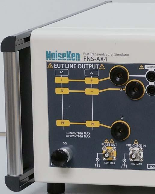
4 FNS-AX4-A20/B63 Feature Easy to perform pre-test inspection with pre-check function In the inspection prior to the test, a dedicated attenuator and an oscilloscope were required for waveform output check. Now FNS- AX4 has a built-in monitor circuit, makes it easy to perform pre-check inspection before testing by just connecting the waveform observation connector with the attached coaxial cable. Simple and Easy EUT power line connection Injection phase indicator on front panel In order to prevent mistakes in the connection of the power cable during the test, Front panel shows the connection destination at a glance. Also an outlet box (option) is available for the simple power connection. Coupling Balun ready for normal mode test IEC standard has the provision of the common mode test only, but noise may enter the equipment in the normal mode in the field and malfunction may occur. ANSI C standard specifies for corresponding normal mode noise testing. FNS-AX4 can now perform the normal mode test complying with ANSI C standard with an optional dedicated normal mode coupling balun.. Easy to understand test settings in "multi-language" In addition to Japanese, operation in English, Korean, and Chinese are provided for easy understanding of the test setting and operation. Remote control Software is available Android application in addition to Windows software is available for customer environment for setting test conditions, saving test results, recording test logs, report generation, etc..

5 FAST T R A NSI ENT BURST SIMUL ATOR FNS-AX4-A20/B63 OUTPUT Waveform PULSE OUT connector waveform: 50Ω EUT LINE OUTPUT waveform 50Ω Repetitive pulses output as burst Front Panel / Rear Panel Front Panel Rear Panel w w w. n o i s e k e n. c o. j p 5


 Sequence mode test screen (For")
6 FNS-AX4-A20/B63 Windows software Remote control from Windows PC is possible using optional Optical USB modulemodel a Test Log Manual Test/ Sequential test will create test log and setting file and saved automatically Setting file is named automatically from the tested year/month/date/time. With software setting, you can enable or disable test log saving and also set folder location of the setting files saved. You can restore the testing condition saved in the test log to re-test with the previously saved condition. Next calibration date notification Following notification will be shown when it is the date set as notified date. It is simply set by the pop-up calendar Manual mode test screen (For Manual setting) Standard mode test screen (For IEC standard testing) Sequence mode test screen (For sequence test) In Manual mode, A balloon show up to indicate setting limitation by just placing mouse pointer. Balloon display can be enabled or disabled.


 Manual mode test screen (For Manual setting) Sweep mode")
7 FAST TRANSIENT BURST SIMULATOR FNS-AX4-A20/B63 Android Application Remote control from Android tablet is possible using Optical Interface box and Bluetooth RS-232C conversion adapter. Test Log Test will save test log as DATA LIST and can be restored for re-testing with the saved condition Photo shot You can take a photo shot of the actual test situation and save it as test log. It simplifies generating reports Standard mode test screen (For IEC standard testing) Manual mode test screen (For Manual setting) Sweep mode test screen (For sweep test) Sequence mode test screen (For sequence test)


8 Option Coupling Clamp MODEL: A Normal mode coupling balun Model: A Outlet boxmodel a Horizontal coupling platemodel a Test tablemodel a Ground planemodel a Insulating blockmodel a Cubic insulator blockmodel a Insulating supportmodel a SG cablemodel a Warning LampMODEL A Tri-color pilot lightmodel a


9 FAST TRANSIENT BURST SIMULATOR Option Attenuator for waveform checkmodel a Attenuator for waveform checkmodel a OPTICAL INTERFACE BOXMODEL A Optical USB modulemodel a EMS Probes Kit MODEL: H2-B Noise Injection Probe MODEL: A Noise simulator Coaxial cable Coupling capacitor Discharge tip Ground clip Radiation Probes MODEL: A / 7A / 8A / 9A / 10A /31A /50A


10 Option Coupling Adapter MODEL: CA 805B Coupling Adaptor MODEL: A (CA 806) Coupling Fixture for High Frequency Surge Test
11 FAST TRANSIENT BURST SIMULATOR IEC Ed.3 Test Standard The Test Standard for evaluating immunity of electric / electronic equipment when they are interfered by fast transient repetitive bursts which are generated by break of inductive load equipment or bounds of relay contact point. Open circuit output test voltage and repetition rate of the impulses On power port, PE On I/O (input/output) signal, data and control ports Level Voltage peak (kv) Repetition rate (khz) Voltage peak (kv) Repetition rate (khz) or or or or or or or or 100 X Special Special Special Special Circuit diagram of a fast transient/burst generator Waveshape of a single pulse into a 50 load Waveshape of a single pulse into a 1k load Rc Switch Rm Cd 50 Coaxial output Normarized voltage Normarized voltage U Rs U Rc High-voltage source Charging resistor Energy storage capacitor Rs Rm Cd Impulse duration shaping resistor Impedance matching resistor DC. blocking capacitor 0.1 5ns±30% 50ns±30% t 0.1 5ns±30% 35ns~150ns t Pulse wave shape into a 50 load and general graph of a fast transient/burst U Pulse U Burst 200s at 5kHz 10s at 100kHz 1/repetition frequency T 15ms at 5kHz 0.7ms at 100kHz Burst duration Burst period 300ms T CDN for AC/DC power mains supply ports/terminals AC mains supply Signal from test generator Capacitive couplin clamp 1000 L1 L2 L3 N PE Filtering 100μH Decoupling section Ferrites CC33nF Coupling section Components L1,L2,L3 N phases neutral L1 L2 L3 N PE Reference ground connector PE EUT protective earth coupling capacitor High-voltage coaxial connector Coupling plates 1000 Insulating supports High-voltage coaxial connector
 Connect between input of waveform verification attenuator 00-00017A and PULSE OUT of the")
12 IEC Ed.3 Test Standard Waveform Verification on 50 load (In case of using waveform verification attenuator A) Connect between input of waveform verification attenuator A and PULSE OUT of the test equipment using coaxial cable comes with the attenuator (HN(P)-NMHV(P)). Also connect between oscilloscope input and output connector of the attenuator using coaxial cable comes with the test equipment (N(P)-BNC(P)). Add an attenuator to oscilloscope if necessary. Input impedance of oscilloscope shall be set to 50 ohm because output impedance of A is 50 ohm. START the test equipment generator. Directly connect the input of waveform verification attenuator A and PULSE OUT of the test equipment. Also connect between oscilloscope input and output connector of the attenuator using coaxial cable comes with the test equipment (N(P)-BNC(P)). Add an attenuator to the oscilloscope if necessary. Input impedance of oscilloscope shall be set to 50 ohm because output impedance of A is 50 ohm. START the test equipment generator. Waveform Verification on 1k load (In case of using Waveform verification attenuator A) Waveform verification at EUT LINE OUT (using A and A) Use a waveform verification connector( a) in the accessary onto EUT LINE OUTPUT and ground reference socket. Set the simulator to inject all phases and verify waveform of each OUTPUT LINE. Insert the waveform verification connector straight onto EUT LINE OUTPUT connector and ground reference socket next to the connector. Be sure to insert deep and secure. Connect between input connectors of waveform verification attenuator A and the waveform verification adapter using coaxial cable comes with the attenuator (HN(P)-NMHV(P)). Also connect between oscilloscope input and output connector of the attenuator using coaxial cable comes with the test equipment (N(P)-BNC(P)). Add an attenuator to the oscilloscope if necessary. Input impedance of oscilloscope shall be set to 50 ohm because output impedance of A is 50 ohm. START the test equipment generator. Signal from test generator AC mains supply L1 L2 L1 L2 L3 L3 EUT N PE Filtering 100μH Decoupling section Ferrites CC33nF Coupling section Components L1,L2,L3 phases N neutral N PE Reference ground connector PE protective earth coupling capacitor
13 FAST TRANSIENT BURST SIMULATOR IEC Ed.3 Test Standard Test Method to Power Supply Lines Put the simulator onto ground reference plane which is connected to the protective ground and connect SG terminal on the front panel to the ground reference plane. Place an insulating support (whose thickness is 10cm) onto the ground reference plane and put EUT on the support (so that the EUT can be isolated from the ground reference plane). Connect LINE OUT on the front panel of the simulator to EUT with a cable (whose length is 50cm) and start operation of EUT. Set the required test conditions (like the burst voltage, etc.) and start the test.
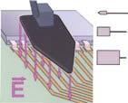
14 IEC Ed.3 Test Standard Test Method to Interconnection Lines ① Put the simulator onto ground reference plane which is connected to the protective ground and connect SG terminal on the front panel to the ground reference plane. ② Place the coupling clamp (Option) onto the ground reference plane. ③ Connect PULSE OUT port to connector of the coupling clamp. ④ Pass the line cable through the coupling clamp. Adjust the clamping part so that the coupling capacity can be largest (space between the cable and clamp can be minimum). ⑤ Cover the coupling clamp for preventing the electrical shock, Set the required test conditions (like the burst voltage, etc.) Decoupling circuit such as ferrite core Fast Transient Burst Simulator FNS-AX4 Power supply for simulator Power supply for AE AE Protective ground Power supply for EUT EUT 0.1 m Coupling clamp Distance between clamp and AE is arbitrary. 0.1 m Insulating support Ground plane ( A) For table-top equipment : 0.5m Insulating support +0.1m 0m For floor-standing equipment : 1.0m±0.1m (between EUT port and coupling clamp) For table-top equipment : 0.5m +0.1m 0m For floor-standing equipment : 1.0m±0.1m EUT Capacitive coupling clamp AE To AC power supply To AC power supply 0.1m Insulating support Grounding connection according to the manufacturer s specification Length to be specified in the test plan m Insulating support Ground reference plane to EFT/B generator 0.1m Grounding connection according to the manufacturer s specification Length to be specified in the test plan w w w. n o i s e k e n. c o. j p
15 FAST TRANSIENT BURST SIMULATOR IEC Ed.3 Test Standard The test shall be carried out on the basis of a test plan that shall include the verification of the performances of the EUT as defined in the technical specification. Type of test that will be carried out; Test level; Polarity of the test voltage (both polarities are mandatory); Internal or external generator; Duration of the test not less than 1 min Test Method using various clamps (outside of IEC compliance testing) Test Method using Fast Transient / Burst Simulator Place the simulator onto the ground plane which is connected to the protective earth and connect SG terminal on the front panel to the ground plane. Connect power cable (Standard accessory) to AC IN on the back of the simulator. Place coupling adaptor CA-805B (Option) onto the ground plane and connect G terminal on side connector part of the clamp to the ground plane. Connect PULSE OUT connector on the front of the simulator to connector of the adaptor. (Fully pay attention to that any high voltage must not be put out during the connection) Clamp the interconnection lines to be tested with the adaptor. Set the test conditions like the coupling voltage, etc., by the touch-panel on the simulator and start the test.
16 International Sales & Marketing Section Chiyoda, Chuo-ku, Sagamihara City, Kanagawa Pref Japan TEL: +81-(0) FAX: +81-(0) sales@noiseken.com Authorized representative K
Fast Transient / Burst Simulator
 EMC TESTS EQUIPMENTS CATALOGUE Fast Transient / Burst Simulator Reproduce showering arc at switching on/off of electric point of contact A simulator to reproduce fast repetitive frequency noises which
Advanced Test Equipment Rentals ATEC (2832) Lightning Surge Simulator LSS-F02.
 Lightning Surge Simulator LSS-F02.") Lightning Surge Simulator Established 1981 Advanced Test Equipment Rentals www.atecorp.com 800-404-ATEC (2832) LSS-F02 www.noiseken.com Conforming to IEC61000-4-5 ed2 Standard LSS-F02 series A simulator
Lightning Surge Simulator Established 1981 Advanced Test Equipment Rentals www.atecorp.com 800-404-ATEC (2832) LSS-F02 www.noiseken.com Conforming to IEC61000-4-5 ed2 Standard LSS-F02 series A simulator
IEC Electrical fast transient / Burst immunity test
 CONDUCTED RF EQUIPMENT POWER AMPLIFIERS IEC 61000-4-4 Electrical fast transient / Burst immunity test IEC 61000-4-4 Electrical fast transient / Burst immunity test Markus Fuhrer Phenomenom open a contact
Lightning Surge Simulator LSS-F03 series
 Lightning Surge Simulator LSS-F03 series Compliant with IEC61000-4-5 Edition 3 requirements Lightning Surge Simulator LSS-F03 series Feature "Output voltage 15kV, current 7500A" which can conduct breakdown
Compliance to a standard or to the real world?
 Compliance to a standard or to the real world? No one could have doubt as to the importance of the pulsed EMI test. In fact, in the scheme of international compliance, the Electrical Fast Transient/ Burst
Technical Specification
 LARGEST RANGE OF IMPULSE TESTERS UP TO 100KV/100KA Technical Specification No. E-MIG0603IN2.doc revised: 20.October 2004 1 MIG Tester Type MIG0603IN2 1 MIG Tester Type MIG0603IN2 1 1.1 Introduction 1 2
Technical Specification
 LARGEST RANGE OF IMPULSE TESTERS UP TO 100KV/100KA Technical Specification E-MIG1203CWG revised: 22. June 2003 1 MIG Tester Type MIG1203CWG 1 MIG Tester Type MIG1203CWG 1 1.1 Introduction 1 2 General 2
Automotive Transient Surge Simulator conforming to ISO ISS-7600 Series
 Automotive Transient Surge Simulator conforming to ISO7637-2 ISS-7600 Series Designed to meet and exceed the testing needs to ISO7637-2 (2004), NoiseKen ISS-7600 series Automotive Transient Surge Simulator
Surge Generator for MIL-STD 1275
 Surge Generator for MIL-STD 1275 This generator PG1275 is specially designed for the test of the susceptibility to surges and spikes of military 28 Vdc electric circuits. The equipment allows performing
EMC TEST REPORT For MPP SOLAR INC Inverter/ Charger Model Number : PIP 4048HS
 EMC-E20130903E EMC TEST REPORT For MPP SOLAR INC Inverter/ Charger Model Number : PIP 4048HS Prepared for : MPP SOLAR INC Address : 4F, NO. 50-1, SECTION 1, HSIN-SHENG S. RD. TAIPEI, TAIWAN Prepared by
Schlöder GmbH - EMC Test and Measurement Systems Model #
 Schlöder GmbH - EMC Test and Measurement Systems Model # Product Description IEC / EN 61000-4 - 2 ESD SESD 216 ESD generator 10 kv CON / 16,5 kv AIR acc. to IEC 61000-4-2, 150 pf / 330 ohm SESD 230 ESD
CAR - TEST - SYSTEM 14
 CAR - TEST - SYSTEM 14 EMC-Test Equipment for electrical installation of vehicles Acc. to ISO 7637-2, ISO 16750-2 ISO 21848 Rise time variable 1-5µs Pulse Waveforms : #1 1-5/2000µs, 600 V, ISO 1-5/1000µs,
Coupling- / Decoupling Network. 150 khz 300 MHz. 150 khz 230 MHz. 10 khz 230 MHz. IEC and CISPR 15 / CISPR 22 IEC
 Coupling- / Decoupling Network 150 khz 300 MHz IEC 61000-4 - 6 and CISPR 15 / CISPR 22 150 khz 230 MHz IEC 61000-4 - 6 10 khz 230 MHz IEC 61000-4 - 6 and IEC 61326-3 - 2 and NE-21 Coupling and decoupling
Coupling/Decoupling Networks (CDN)
") Coupling/Decoupling Networks (CDN) For immunity testing according to IEC / EN 61000-4-6 Immunity testing CDNs are the preferred coupling and decoupling devices, for reasons of test reproducibility and
Coupling/Decoupling Networks (CDN) For immunity testing according to IEC / EN 61000-4-6 Immunity testing CDNs are the preferred coupling and decoupling devices, for reasons of test reproducibility and
OCS 500N6F SERIES SIMULATOR FOR FAST AND SLOW DAMPED OSCILLATORY WAVES AND RINGWAVE
 OCS 500N6F SERIES SIMULATOR FOR FAST AND SLOW DAMPED OSCILLATORY WAVES AND RINGWAVE FOR TESTS ACCORDING TO... > ANSI/IEEE C37.90 > ANSI/IEEE C62.41 > EN 61000-4-10 > EN 61000-4-12 > EN 61000-4-18 > IEC
EMC PARTNER. DO-160 & MIL-STD-461G TEST SYSTEM Indirect Lightning Testing
 EMC PARTNER DO-160 & MIL-STD-461G TEST SYSTEM Indirect Lightning Testing This document has been optimized for electronic media Accredited Calibration Quality at EMC PARTNER is based on an ISO 9001 management
2620 Modular Measurement and Control System
 European Union (EU) Council Directive 89/336/EEC Electromagnetic Compatibility (EMC) Test Report 2620 Modular Measurement and Control System Sensoray March 31, 2006 April 4, 2006 Tests Conducted by: ElectroMagnetic
Advanced Test Equipment Rentals ATEC (2832)
") Established 1981 Advanced Test Equipment Rentals www.atecorp.com 800-404-ATEC (2832) 1 MIG Tester Type MIG2000-6 Technical Specification E-MIG2000-6 revised: 07. May 2009 1 MIG Tester Type MIG2000-6 1
Established 1981 Advanced Test Equipment Rentals www.atecorp.com 800-404-ATEC (2832) 1 MIG Tester Type MIG2000-6 Technical Specification E-MIG2000-6 revised: 07. May 2009 1 MIG Tester Type MIG2000-6 1
EMC standards. Presented by: Karim Loukil & Kaïs Siala
 Training Course on Conformity and Interoperability on Type Approval testing for Mobile Terminals, Homologation Procedures and Market Surveillance, Tunis-Tunisia, from 20 to 24 April 2015 EMC standards
Overview of EMC Regulations and Testing. Prof. Tzong-Lin Wu Department of Electrical Engineering National Taiwan University
 Overview of EMC Regulations and Testing Prof. Tzong-Lin Wu Department of Electrical Engineering National Taiwan University What is EMC Electro-Magnetic Compatibility ( 電磁相容 ) EMC EMI (Interference) Conducted
Conducted Immunity Testing
 EMC PARTNER COMPLETE TEST SOLUTIONS FOR Conducted Immunity Testing This document has been optimized for electronic media Accredited Calibration Quality at EMC PARTNER is based on an ISO 9001 management
EMC TEST REPORT. For. Switching Mode Power Adaptor. Model No.: 9W/14.4V/EU(18V/1.0A), 19W/14.4V/EU(12V/1.5A)
, 19W/14.4V/EU(12V/1.5A)") EMC TEST REPORT For Company Limited Liability «Faraday Electronics» Switching Mode Power Adaptor Model No.: 9W/14.4V/EU(18V/1.0A), 19W/14.4V/EU(12V/1.5A) Prepared For : Company Limited Liability «Faraday
EMC TEST REPORT For Company Limited Liability «Faraday Electronics» Switching Mode Power Adaptor Model No.: 9W/14.4V/EU(18V/1.0A), 19W/14.4V/EU(12V/1.5A) Prepared For : Company Limited Liability «Faraday
PURCHASE DIVISION DEPARTMENT QUALITY MANUAL Revision No. : 02 Issue No: : 2 Dt of Revision : Issue Dt. :
 Section : 0 Document : DQM-01 Topic : FORMAT 6 OF PROCUREMENT PROCEDURE OF CPRI (NON-WORKS) Section I(B)-Technical Specification Tender Enquery No PUR/UARC-02/14-15 Name of the Equipment: Damped Oscillatory
CS114 + CS115 + CS116
 System description Test Setup for MIL-STD-461 D, E&F CS114 + CS115 + CS116 1. MONTENA EMC... 2 1.1 PRODUCTS... 3 1.2 TURN KEY MIL STD 461 TEST INSTALLATIONS... 3 2. TEST SETUP DESCRIPTION... 4 2.1 TEST
Novità sulla IEC ; -10; -12
 Novità sulla IEC 61000-4-9; -10; -12 DIPL. ING. MARKUS FUHRER 11.06.2018 Content Recently revised standards IEC 61000-4-9 Ed. 2.0 2016-07 Impulse magnetic field IEC 61000-4-10 Ed. 2.0 2016-07 Damped oscillatory
OSCILLOSCOPES. Oscilloscopes CS-5300 SERIES RS-232C OPTION OPTION CS-5370P/5370/5350 FEATURES OUTLINE. Photo: CS-5370P
 Oscilloscopes 100MHz 2-Channel Programmable Oscilloscope ( With Digital Readout / Cursor) CS-5370P CS-5370 100MHz 3-Channel Oscilloscope ( With Digital Readout / Cursor) 50MHz 3-Channel Oscilloscope (
LS200 TEST DATA IEC61000 SERIES
 TEST DATA IEC61000 SERIES DWG. No. PA607-58-01 APPD CHK DWG TDK-Lambda INDEX LS200 PAGE 1. Electrostatic Discharge Immunity Test (IEC61000-4-2) R-1 2. Radiated Radio-Frequency Electromagnetic Field Immunity
EMC Seminar Series All about EMC Testing and Measurement Seminar 1
 EMC Seminar Series All about EMC Testing and Measurement Seminar 1 Introduction to EMC Conducted Immunity Jeffrey Tsang Organized by : Department of Electronic Engineering 1 Basic Immunity Standards: IEC
TECHNICAL REQUIREMENTS FOR ELECTROMAGNETIC DISTURBANCES EMITTED FROM LIGHTING EQUIPMENT INSTALLED IN TELECOMMUNICATION CENTERS
 TR550004 TECHNICAL REQUIREMENTS FOR ELECTROMAGNETIC DISTURBANCES EMITTED FROM LIGHTING EQUIPMENT INSTALLED IN TELECOMMUNICATION CENTERS TR NO. 174001 EDITION 2.1 September 3 rd, 2018 Nippon Telegraph and
Coupling/Decoupling Networks (CDN)
") Coupling/Decoupling Networks (CDN) For immunity testing according to IEC / EN 61000-4-6 Immunity testing CDNs are the preferred coupling and decoupling devices, for reasons of test reproducibility and
Coupling/Decoupling Networks (CDN) For immunity testing according to IEC / EN 61000-4-6 Immunity testing CDNs are the preferred coupling and decoupling devices, for reasons of test reproducibility and
Voltage Transient Emission Test
 Manual For Operation AN 200 Series Voltage Transient Emission Test AN 200 AN 200B The AN 200 is used to evaluate automotive electrical and electronic components for conducted emissions of transients along
EMC Test Report. Report Number: M030826
 Page 1 of 36 EMC Technologies Pty Ltd ABN 82 057 105 549 57 Assembly Drive Tullamarine Victoria Australia 3043 Ph: + 613 9335 3333 Fax: + 613 9338 9260 email: melb@emctech.com.au EMC Test Report Report
TEST SUMMARY. Prüfbericht - Nr.: Test Report No.: Seite 2 von 25. Page 2 of 25
 15072259 001 Seite 2 von 25 Page 2 of 25 TEST SUMMARY 4.1.1 HARMONICS ON AC MAINS 4.1.2 VOLTAGE FLUCTUATIONS ON AC MAINS 4.1.3 MAINS TERMINAL CONTINUOUS DISTURBANCE VOLTAGE 4.1.4 DISCONTINUOUS INTERFERENCE
Test Specification for Type Approval
 A2 (1991) (Rev.1 1993) (Rev.2 1997) (Rev. 2.1 July 1999) (Rev.3 May 2001) (Corr.1 July 2003) (Rev.4 May 2004) (Rev.5 Dec 2006) (Rev.6 Oct 2014) Test Specification for Type Approval.1 General This Test
COMPACT NX5 MULTIFUNCTIONAL TEST GENERATOR FOR TRANSIENTS (EFT/BURST, SURGE & POWER FAIL) UP TO 5.5 KV
 UP TO 5.5 KV") Established 1981 Advanced Test Equipment Rentals www.atecorp.com 800-404-ATEC (2832) COMPACT NX5 MULTIFUNCTIONAL TEST GENERATOR FOR TRANSIENTS (EFT/BURST, SURGE & POWER FAIL) UP TO 5.5 KV FOR TESTS ACCORDING
Established 1981 Advanced Test Equipment Rentals www.atecorp.com 800-404-ATEC (2832) COMPACT NX5 MULTIFUNCTIONAL TEST GENERATOR FOR TRANSIENTS (EFT/BURST, SURGE & POWER FAIL) UP TO 5.5 KV FOR TESTS ACCORDING
TEST REPORT... 1 CONTENT...
 CONTENT TEST REPORT... 1 CONTENT... 2 1 TEST RESULTS SUMMARY... 3 2 EMC RESULTS CONCLUSION... 4 3 LABORATORY MEASUREMENTS... 6 4 EMI TEST... 7 4.1 CONTINUOUS CONDUCTED DISTURBANCE VOLTAGE TEST... 7 4.2
EN 55015: 2013 Clause Pass. EN 55015: 2013 Clause Pass. EN 55015: 2013 Clause Pass
 Reference No.: WTD15S0730643E Page 2 of 42 1 Test Summary Test Item Conducted Disturbance at Mains Terminal, 9kHz to 30MHz Radiation electromagnetic disturbance, 9kHz to 30MHz Radiation Emission, 30MHz
NORME INTERNATIONALE INTERNATIONAL STANDARD
 NORME INTERNATIONALE INTERNATIONAL STANDARD CEI IEC 61000-4-4 Deuxième édition Second edition 2004-07 PUBLICATION FONDAMENTALE EN CEM BASIC EMC PUBLICATION Compatibilité électromagnétique (CEM) Partie
RF Conducted Immunity and Automotive Transient Generator Test Systems
 August 2008 RF Conducted Immunity and Automotive Transient Generator Test Systems rf/microwave instrumentation 1 This Will Get Your Pulse Going at whatever rate you need! DUT Coupling Network TGA20000
Model 310H Fast 800V Pulse Generator
 KEY FEATURES Temperature Stability +/-5ppm 100 V to 800 V into 50 Ω
Arbitrary/Function Waveform Generators 4075B Series
 Data Sheet Arbitrary/Function Waveform Generators Point-by-Point Signal Integrity The Arbitrary/Function Waveform Generators are versatile high-performance single- and dual-channel arbitrary waveform generators
RIGOL Data Sheet. DG3000 Series Function/Arbitrary Waveform Generator DG3121A, DG3101A, DG3061A. Product Overview. Easy to Use Design.
 RIGOL Data Sheet DG3000 Series Function/Arbitrary Waveform Generator DG3121A, DG3101A, DG3061A Product Overview DG3000 Series Function/Arbitrary Waveform Generators adopt DDS technology, which enables
COMPACT NX5 SERIES MULTIFUNCTIONAL TEST GENERATOR FOR TRANSIENTS (EFT/BURST, SURGE & POWER FAIL) UP TO 5.5 KV
 UP TO 5.5 KV") COMPACT NX5 SERIES MULTIFUNCTIONAL TEST GENERATOR FOR TRANSIENTS (EFT/BURST, SURGE & POWER FAIL) UP TO 5.5 KV FOR TESTS ACCORDING TO... > IEC 61000-4-4 > IEC 61000-4-5 > IEC 61000-4-8 > IEC 61000-4-9 >
COMPACT NX5 SERIES MULTIFUNCTIONAL TEST GENERATOR FOR TRANSIENTS (EFT/BURST, SURGE & POWER FAIL) UP TO 5.5 KV FOR TESTS ACCORDING TO... > IEC 61000-4-4 > IEC 61000-4-5 > IEC 61000-4-8 > IEC 61000-4-9 >
MODEL 9050 EXTENDED SPECIFICATIONS. 50ppm TRANSPORTABLE CALIBRATOR
 MODEL 9050 EXTENDED SPECIFICATIONS Ü 50ppm TRANSPORTABLE CALIBRATOR 9050A EXTENDED SPECIFICATIONS General Specifications TRANSMILLE LTD Warm Up Time Double the time since last used up to 20 minutes maximum
SCOPE OF ACCREDITATION TO ISO/IEC 17025:2005 AMETEK CO., LTD. NAGOYA OFFICE. (Main Laboratory) Onna, Atsugi-shi, Kanagawa-ken, Japan
 Onna, Atsugi-shi, Kanagawa-ken, Japan") SCOPE OF ACCREDITATION TO ISO/IEC 17025:2005 AMETEK CO., LTD. NAGOYA OFFICE (Main Laboratory) 5-1-1 Onna, Atsugi-shi, Kanagawa-ken, 243-0032 Japan (Commercial Office) 1-329 Kifune, Meito-ku Nagoya-shi,
SCOPE OF ACCREDITATION TO ISO/IEC 17025:2005 AMETEK CO., LTD. NAGOYA OFFICE (Main Laboratory) 5-1-1 Onna, Atsugi-shi, Kanagawa-ken, 243-0032 Japan (Commercial Office) 1-329 Kifune, Meito-ku Nagoya-shi,
Immunity Testing for the CE Mark
 Immunity Testing for the CE Mark Summary The European Union (EU) currently has 25 member countries with 2 additional countries to be added in 2007. The total population at that time will be nearly a half
EN :2007+A1:2011 Electromagnetic compatibility Emission standard for residential, commercial and light-industrial environments
 EMC Page 3 / 33 Test report No.: EN 61000-6-3:2007+A1:2011 Electromagnetic compatibility Emission standard for residential, commercial and light-industrial environments Date of measurement: 2013-10-16
A Comparison Between MIL-STD and Commercial EMC Requirements Part 2. By Vincent W. Greb President, EMC Integrity, Inc.
 A Comparison Between MIL-STD and Commercial EMC Requirements Part 2 By Vincent W. Greb President, EMC Integrity, Inc. OVERVIEW Compare and contrast military (i.e., MIL-STD) and commercial EMC immunity
Bench LCR Meter Model 891
 Data Sheet Bench LCR Meter The 891 is a compact, precise, and versatile LCR meter capable of measuring inductors, capacitors, and resistors at DC or from 20 Hz to 300 khz. The instrument s 2U half-rack
ELEC 0017: ELECTROMAGNETIC COMPATIBILITY LABORATORY SESSIONS
 Academic Year 2015-2016 ELEC 0017: ELECTROMAGNETIC COMPATIBILITY LABORATORY SESSIONS V. BEAUVOIS P. BEERTEN C. GEUZAINE 1 CONTENTS: EMC laboratory session 1: EMC tests of a commercial Christmas LED light
Specification for Conducted Emission Test
 1 of 10 1. EMI Receiver Frequency range 9kHz 7.0 GHz Measurement time per frequency 10 µs to 100 s time sweep, span = 0 Hz - 1 µs to 16000 s Sweep time in steps of 5 % frequency sweep, span 10 Hz - 2.5
TEST SUMMARY. Prüfbericht - Nr.: Test Report No.: Seite 2 von 27. Page 2 of 27
 15072768 001 Seite 2 von 27 Page 2 of 27 TEST SUMMARY 4.1.1 HARMONICS ON AC MAINS 4.1.2 VOLTAGE CHANGES, VOLTAGE FLUCTUATIONS AND FLICKER ON AC MAINS 4.1.3 MAINS TERMINAL CONTINUOUS DISTURBANCE VOLTAGE
EMC TEST REPORT. for. Coliy Technology Co.,Ltd. Fluxgate Gaussmeter
 Page 1 of 48 EMC TEST REPORT for Coliy Technology Co.,Ltd. Fluxgate Gaussmeter Prepared for : Coliy Technology Co.,Ltd. Address : Block B,9 th Floor,Xinzhongtai Business Building,Gushu 2nd Road,Xi Town,Bao
DECLARATION OF CONFORMITY
 DECLARATION OF CONFORMITY Manufacturer's Name: Transmille Ltd. Manufacturer's Address: Unit 4, Select Business Centre Lodge Road Staplehurst TN12 0QW. United Kingdom. Declares, that the product Product
2520 Pulsed Laser Diode Test System
 Complete pulse test of laser diode bars and chips with dual photocurrent measurement channels 0 Pulsed Laser Diode Test System Simplifies laser diode L-I-V testing prior to packaging or active temperature
NSG Hard keys for important functions. 5.7 color display, easy to use firmware. 3 power meter
 The, successor of the NSG 070, is a multifunctional EMC immunity test system. Its large frequency range from to G and its modular set-up using internal or external amplifiers enable a large variety of
C.A Complete electrical network analysis at the tips of your fingers! Power Quality Monitor. Keeping up with the standards
 Keeping up with the standards C.A 8352 Power Quality Monitor Complete electrical network analysis at the tips of your fingers! All measurements for complete analysis: powers, harmonics, flicker, symmetry,
500 khz / 1 MHz Precision LCR Meter Models 894 & 895
 Data Sheet 500 khz / 1 MHz Precision LCR Meter 99 Washington Street Melrose, MA 02176 Phone 781-665-1400 Toll Free 1-800-517-8431 Visit us at www.testequipmentdepot.com Industry-Leading Performance The
500 khz / 1 MHz Precision LCR Meter Models 894 & 895
 Data Sheet 500 khz / 1 MHz Precision LCR Meter Industry-Leading Performance The 894 and 895 are high accuracy LCR meters capable of measuring inductance, capacitance, and resistance of components and materials
Digital Function Generator
 Digital Function Generator 13654-99 PHYWE Systeme GmbH & Co. KG Robert-Bosch-Breite 10 37079 Göttingen Germany Tel. +49 (0) 551 604-0 Fax +49 (0) 551 604-107 E-mail info@phywe.de Operating Instructions
Overcurrent Protection / 7SJ45
 Overcurrent Protection / SJ SIPROTEC easy SJ numerical overcurrent protection relay powered by CTs Fig. / Description SIPROTEC easy SJ numerical overcurrent protection relay powered by current transformers
EMC TEST REPORT. For. Soma Medical (Sabah) Sdn Bhd ( D) UVGI AIR STERILIZER. Model No.: SM 20
 Sdn Bhd ( D) UVGI AIR STERILIZER. Model No.: SM 20") EMC TEST REPORT For Soma Medical (Sabah) Sdn Bhd (1248058-D) UVGI AIR STERILIZER Model No.: SM 20 Prepared For : Soma Medical (Sabah) Sdn Bhd (1248058-D) : Block E, Lot 28, 2nd floor, Signature Office,
EMC TEST REPORT For Soma Medical (Sabah) Sdn Bhd (1248058-D) UVGI AIR STERILIZER Model No.: SM 20 Prepared For : Soma Medical (Sabah) Sdn Bhd (1248058-D) : Block E, Lot 28, 2nd floor, Signature Office,
DRTS 66 The new generation of advanced test equipments for Relays, Energy meters, Transducers and Power quality meters
 The new generation of advanced test equipments for Relays, Energy meters, Transducers and Power quality meters Testing all relay technologies: electromechanical, solid state, numerical and IEC61850 Manual
TesT system for ConduCTed and radiated immunity
 nsg 070 TesT system for ConduCTed and radiated immunity The, successor of the NSG 070, is a multifunctional EMC immunity test system. Its large frequency range from to G and its modular set-up using internal
V1.3. TBLC08 50mH AC-LISN TBLC08
 V1.3 TBLC08 The TBLC08 is a Line Impedance Stabilization Network for the measurement of line-conducted interference within the range of 9kHz to 30MHz, according to the CISPR16 standard. The device is designed
Experiment 1.A. Working with Lab Equipment. ECEN 2270 Electronics Design Laboratory 1
 .A Working with Lab Equipment Electronics Design Laboratory 1 1.A.0 1.A.1 3 1.A.4 Procedures Turn in your Pre Lab before doing anything else Setup the lab waveform generator to output desired test waveforms,
Test Report. Guangdong East Power Co., Ltd. Fully Automatic AC Voltage Regulator. Brand Name:
 Test Report Applicant: Product Name: Brand Name: Model No.: Guangdong East Power Co., Ltd. Fully Automatic AC Voltage Regulator EAST ZTY-30KVA Date of Receipt : Aug. 30, 2013 Date of Test: Sep. 03, 2013
TEST SYSTEM FOR CONDUCTED AND RADIATED IMMUNITY
 TEST SYSTEM FOR CONDUCTED AND RADIATED IMMUNITY Integrated signal generator to G power meter inputs to G Integrated class A power amplifier module for different applications: W, 0 to 0 ; 0 W, 0 to 00 ;
TEST SYSTEM FOR CONDUCTED AND RADIATED IMMUNITY
 C TEST SYSTEM FOR CONDUCTED AND RADIATED IMMUNITY Integrated signal generator to G power meter inputs to G Integrated class A power amplifier module for different applications: W, 0 to 0 ; 0 W, 0 to 00
EN61326 EMC COMPLIANCE REPORT on the LP Series Ultrasonic Transmitter Remote Amplifier and Transducer for Hawk Measurement Systems Pty Ltd
 Page 1 of 15 EMC Technologies Pty Ltd ABN 82 057 105 549 57 Assembly Drive Tullamarine Victoria Australia 3043 Ph: + 613 9335 3333 Fax: + 613 9338 9260 email: melb@emctech.com.au EN61326 EMC COMPLIANCE
automotive EMC solutions
 automotive EMC solutions 1 2 3 4 5 : transient immunity simulator APS/APG series: environmental conditions of power supply test PAWG series arbitrary waveform generator LDS 200 series: automotive load
OSCILLOSCOPES. Oscilloscopes CS-5400 SERIES CS-5400/5450 FEATURES OUTLINE CS-5400
 99 Washington Street Melrose, MA 02176 Fax 781-665-0780 TestEquipmentDepot.com Oscilloscopes 100MHz 3-Channel Oscilloscope (With Digital Readout / Cursor) CS-5400 100MHz 3-Channel Oscilloscope CS-5405
Test Report GUANGDONG EAST POWER CO., LTD
 Test Report Applicant: Product Name: Brand Name: Model No.: GUANGDONG EAST POWER CO., LTD Online High Frequency UPS EAST EA906IIRTS, EA906IIRTH Date of Receipt : Feb. 26, 2014 Date of Test: Mar. 24, 2014
MILITARY & AEROSPACE TESTING
 EMC PARTNER CONDUCTED SUSCEPTIBILITY MILITARY & AEROSPACE TESTING WHEN GETTING RESULTS MATTERS THERE IS ONLY ONE CHOICE Military and avionic testing is all about quality and precision. MIL3000 brilliantly
MS2109A AC/DC Clamp Meter. User Manual. Contents
 MS2109A AC/DC Clamp Meter User Manual Contents 1. Safety information 1 1.1 Preparation 1 1.2 Usage 1 1.3 Signs and Labels 2 1.4 Maintenance 2 2. Description 2 2.1 Part name 3 2.2 Switch and button description
MIL Standard 461 G. final release December 11 th, EMC PARTNER - Largest range of impulse test equipment up to 100kV and 100kA
 MIL Standard 461 G final release December 11 th, 2015 EMC PARTNER - Largest range of impulse test equipment up to 100kV and 100kA CDN-UTP8 Ed. 3 - Universal The Swiss CDN company for data EMC and telecom
RIGOL Data Sheet. DG2000 Series Function/Arbitrary Waveform Generator DG2041A, DG2021A. Product Overview. Main Features.
 RIGOL Data Sheet DG2000 Series Function/Arbitrary Waveform Generator DG2041A, DG2021A Product Overview DG2000 Series Function/Arbitrary Waveform Generators adopt DDS technology, which enables to generate
MS8250A/B OPERATION MANUAL MS8250A. Hz% FUNC REL RANGE REL HOLD OFF 10A. Hz% A NCV. Hz% COM. A ma 10A FUSED 600V CAT IV.
 MS8250A/B DIGITAL MULTIMETER OPERATION MANUAL AUTO DC AC REL hfe PCLINK % C F kmωkz nµmfav MS8250A DIGITAL MULTIMETER Auto Power Off RANGE REL HOLD FUNC NCV A ma OFF 10A A ma 10A FUSED 600V CAT IV COM
COUPLING / DECOUPLING NETWORK (CDN) CDN AF TYPE, CDN CAN
 CDN AF TYPE, CDN CAN") IEC / EN 61000-4-6 specifies the design and performance of a range of coupling / decoupling networks (CDNs). Each CDN is specific to the of cable and the intended signal carried on the cable. Teseq offers
IEC / EN 61000-4-6 specifies the design and performance of a range of coupling / decoupling networks (CDNs). Each CDN is specific to the of cable and the intended signal carried on the cable. Teseq offers
Agilent Technologies 3000 Series Oscilloscopes
 Agilent Technologies 3000 Series Oscilloscopes Data Sheet Full-featured oscilloscopes for the smallest budgets Features: 60 to 200 MHz bandwidths 1 GSa/s maximum sample rate Large 15-cm (5.7-in) color
MODEL745 FOUR CHANNEL DIGITAL DELAY/ PULSE GENERATOR
 MODEL745 FOUR CHANNEL DIGITAL DELAY/ PULSE GENERATOR Four delay and width channels 250 fs delay resolution Jitter as low as 5 ps rms for internally-triggered delays Jitter as low as 25ps rms for externally-triggered
Fluke 192/196/199. MS 190 and MA 190. Users Manual Supplement
 Fluke 192/196/199 MS 190 and MA 190 Users Manual Supplement 4822 872 00979 April 2000, Rev.2, 9/00 2000 Fluke Corporation. All rights reserved. Printed in the Netherlands. All product names are trademarks
MODEL 9041 EXTENDED SPECIFICATIONS. 25ppm TRANSPORTABLE CALIBRATOR
 MODEL 9041 EXTENDED SPECIFICATIONS 25ppm TRANSPORTABLE CALIBRATOR 9041 EXTENDED SPECIFICATIONS General Specifications TRANSMILLE LTD Warm Up Time Double the time since last used up to 20 minutes maximum
EMC VERIFICATION SUMMARY Report No.: SZHH
 EMC VERIFICATION SUMMARY Toy ITE Others Additional Models: 0801 to 0899 INCLUSIVE, 0804, 0804W, 0805, 0806, 0807, 0808, 0809, 0811, 0811W, 0812, 0813, 0814,0815, 0816, 0817,0817 ROOM 619, 6/F. PENINSULA
Green LED (right of 'D' type connector)
") 3050A EXTENDED SPECIFICATIONS General Specifications TRANSMILLE LTD Warm Up Time Double the time since last used up to 20 minutes maximum Standard Interfaces USB Optional Interfaces GPIB (IEEE-488) : RS232
3050A EXTENDED SPECIFICATIONS General Specifications TRANSMILLE LTD Warm Up Time Double the time since last used up to 20 minutes maximum Standard Interfaces USB Optional Interfaces GPIB (IEEE-488) : RS232
Methods for Testing Impulse Noise Tolerance
 Methods for Testing Impulse Noise Tolerance May,6,2015 Larry Cohen Overview Purpose: Describe some potential test methods for impulse noise tolerance What we will cover in this presentation: Discuss need
Coupling / decoupling network (CDN) for screened or coaxial cables
 for screened or coaxial cables") IEC / EN 61000-4-6 specifies the design and performance of a range of coupling / decoupling networks (CDNs). Each CDN is specific to the type of cable and the intended signal carried on the cable. Teseq
IEC / EN 61000-4-6 specifies the design and performance of a range of coupling / decoupling networks (CDNs). Each CDN is specific to the type of cable and the intended signal carried on the cable. Teseq
TRANSMILLE 3010A PRECISION MULTIPRODUCT CALIBRATOR EXTENDED SPECIFICATIONS
 TRANSMILLE 3010A PRECISION MULTIPRODUCT CALIBRATOR EXTENDED SPECIFICATIONS www. transmille.com 3010A EXTENDED SPECIFICATIONS General Specifications TRANSMILLE LTD Warm Up Time Double the time since last
Transient Data Acquisition System, TAS 4-40 Potential-free measurement of fast rise pulses:
 Transient Data Acquisition System, TAS 4-40 Potential-free measurement of fast rise pulses: High precision measurement of fast rising voltages and currents causes considerable problems in many spheres
EMC Test Report. Product. Model Number. Prepared for : Shenzhen top technology co., LTD Address : No 2.First Rd Of Lucky,Longgang Ping Shenzhen China
 EMC-Report No.:SZZCT1502030B-EMC-02 EMC Test Report Product Model Number : Drift car : P01 Prepared for : Shenzhen top technology co., LTD Address : No 2.First Rd Of Lucky,Longgang Ping Shenzhen China
WaveStation Function/Arbitrary Waveform Generators
 WaveStation Function/Arbitrary Waveform Generators Key Features High performance with 14-bit, 125 MS/s and 16 kpts 2 channels on all models Large 3.5 color display for easy waveform preview Over 40 built-in
TEST SUMMARY Seite 2 von 27. Prüfbericht - Nr.: Test Report No HARMONICS ON AC MAINS RESULT: Passed
 17035561 001 Seite 2 von 27 Page 2 of 27 TEST SUMMARY 5.1.1 HARMONICS ON AC MAINS RESULT: Passed 5.1.2 VOLTAGE FLUCTUATIONS ON AC MAINS RESULT: Passed 5.1.3 TERMINAL CONTINUOUS DISTURBANCE VOLTAGE AT RESULT:
Contents H3CR. DIN 48 x 48-mm Multifunctional Timer Series. Broad Line-up of H3CR Series H3CR-A. Solid-state Timer. Common to ALL Timers
 Solid-state Timer H3CR DIN 48 x 48-mm Multifunctional Timer Series Conforms to EN61812-1 and EN60664-1 (VDE0110) 4 kv/2 for Low Voltage, and EMC Directives. Approved by UL and CSA. Lloyds/NK approvals.
UCS 500N7.2 MULTIFUNCTIONAL TRANSIENT SIMULATOR FOR RENEWABLE ENERGY
 UCS 500N7.2 MULTIFUNCTIONAL TRANSIENT SIMULATOR FOR RENEWABLE ENERGY FOR TESTS ACCORDING TO... > ANSI/IEEE C62.41 > ECE-R10 > EN 61000-4-11 > EN 61000-4-29 > EN 61000-4-4 > EN 61000-4-5 > EN 61000-4-8
WaveStation Function/Arbitrary Waveform Generators
 Function/Arbitrary Waveform Generators Key Features High performance with 14-bit waveform generation, up to 500 MS/s sample rate and up to 512 kpts memory 2 channels on all models Large color display for
EMC TEST REPORT. For. Boardcon Technology Limited. MINI9G45 Computer on Module. Model No. : MINI9G45
 REPORT NO. PRSZ15110502E EMC TEST REPORT For Boardcon Technology Limited. MINI9G45 Computer on Module Model No. : MINI9G45 Prepared For : Boardcon Technology Limited. : Room 702, Hua Feng Xin An Business
Agilent Technologies 3000 Series Oscilloscopes
 Agilent Technologies 3000 Series Oscilloscopes Data Sheet Full-featured oscilloscopes for the smallest budgets Features: 60 to 200 MHz bandwidths 1 GSa/s maximum sample rate Large 15-cm (5.7-in) color
CAL U100B CAL U100B CDN M016 CAL U100B CDN M016 CAL U100B. Used as M2 CDN. Used as M3 CDN
 out < +0 out < +0 ch. < +0 ch. < +0 ch. < +7 ch. < +0 ch. < +0 ch. < +7 LL LL nd nd 0 8... Test setup calibration with a CDN The calibration setup always refers to the type of CDN. The CDN user manuals
PROGRAMMABLE AC POWER SOURCE MODEL 6500 SERIES MODEL 6500 SERIES. Programmable AC Power Source. Key Features:
 Programmable AC Power Source MODEL 6500 SERIES Key Features: PROGRAMMABLE AC POWER SOURCE MODEL 6500 SERIES The global AC power testing requirements demand more sophisticated AC Power Source that is capable
EN 55022: 2010+AC:2011 Clause 6.1 Pass. Harmonic Current EN :2006+A1:2009+A2:2009 Class A N/A
 Reference No.: WT12106773-N-S-E Page 2 of 33 1 Test Summary Test Item Mains Terminal Disturbance Voltage, 150KHz to 30MHz Radiation Emission, 30MHz to 1000MHz EMISSION Test Standard Class / Severity Result