Modern radio techniques
|
|
|
- Benjamin Park
- 5 years ago
- Views:
Transcription
1 Modern radio techniques for probing the ionosphere Receiver, radar, advanced ionospheric sounder, and related techniques Cesidio Bianchi INGV - Roma Italy
2 Ionospheric properties related to radio waves The most useful way to perform systematic measurements in the ionosphere is to use radio waves. This can be done exploiting the properties of the ionosphere when it interacts in various ways with the electromagnetic waves. The radio techniques for probing the ionosphere are spread in nearly all ranges of radio frequency. We explore the structure of the ionosphere by bouncing radio waves of different frequencies on it, and using special receivers to detect how the reflected waves have changed from the transmitted waves. We also examine the changes of the radio waves from satellites transmitted through the ionosphere etc..
3 Techniques - vertical soundings + Doppler shift measurement - incoherent scatter radar - TEC measurement
4
5 Radio & Radar principles The radio is a device that either generates, or responds to radio waves. The radar (radio detector and ranging) is a device able to transmit a pulsed radio wave and receive its echo evaluating also the range and the modification of the transmitted radio wave.
6 Basic requirements for receivers: - Receiving, amplifying and demodulating AM, FM, phase coded waves, etc. ability to tune to a specific signal amplify the signal that is picked up
7 Radio Receiver
8 Superherodyne receiver
9 sections
10 functions & requirements - modulation (amplitude, frequency, phase etc..) (information) -filter (selectivity) - amplifier (dynamic, sensitivity and linearity) - detection (dynamic and linearity) - control (dynamic and linearity, AGC, selectivity)
11 antenna A radio antenna may be defined as a structure associated with the region of transition between a guided wave and free space or vice versa (Kraus)
12 RF front-end
13 Intermediate frequency IF is chosen always lower than RF: more stable (do not oscillate). Usually one RF amplifier, IF stages >2 Mixer- By a local oscillator LO, the RF is converted to IF (RF to IF translation). Shape of the envelope remain the same. BW is unchanged

14 Detection process
15 Detection Two types Coherent (synchronous): frequencies used for demodulation are exact copy of Tx carrier Non-coherent (asynchronous): envelope detection
16 Internal noise The white noise is due to the random motion of the electrons. The voltage across the two resistor terminal at the absolute temperature T is: Vrms=2(KTRB) 0.5 where K is the Boltzmann constant (J/Hz)and B is the band of frequency considered. Under well matched condition the power is P=KTB (W) By definition the noise factor F is: Signal-to-noise ratio(input) / Signal-to-noise ratio (output)
17 Internal noise 2 In the receiver it is useful to define the noise factor F in quantitative way as: F = GPi Pi / KToB /( GKT o B + PA where Pi and PA are the input noise and additional noise measured at amplifier the output The noise figure is ) fnoise = 10 log10 F
18 environment
19 noise & interferences What is important at the antenna level is the signalto-noise ratio (S/N) The noise level does not allow to increase the sensitivity as we desire. Terrestrial environment is continuously exposed to electromagnetic radiations, which set up a background of electromagnetic noise. The electromagnetic background refers to the environment in which there are both natural and manmade electromagnetic noise. Broadcasting stations can cause strong interferences which affect the reception of the signal
20 T X Controller C Radar T/R switch or circulator Receiver R X Display unit
21 Mono static radar
22 Bi-static radar
23 Frequency synthesizer
24 DDS
25 Radar equation The radar equation represents the physical dependences of between the transmitted power and received power. ( λ G ( 4 2 d rad P r = 3 4 π ) ) σ r P
26 Radar eq ( λ G ( 4 2 d rad P r = 3 4 π ) ) σ r P Variable Definition Units P r Power received by the radar antenna λ Wavelength of signal received by radar antenna watts (W) meters (m) G Directive gain of antenna (measure of the d concentration of the radiated power in a particular σ direction) Radar cross section (characterizes the target s ability to scatter or reflect energy) unitless square meters (m 2 ) P rad Power dissipated through the characteristic impedance, Rrad, of the TX radar antenna r Distance measured from the radar to the target watts (W) meters (m)
27 Radar cross section Radar cross section is defined as: = i s E E π r σ where E s and E i are defined as the scattered and incident electric fields, respectively. E s is measured at the receiving antenna, whereas E i is measured at the target level. Since the scattered electric field is inversely proportional to distance, r, the radar cross section reduces to the following: = i s i s E E E r E πr π σ
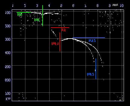
28 ionosondes 1 Envelope detector ionosonde or HF Radar
29 ionosonde block-diagram
30 - The frequency measurement is assured by the receiver selectivity always tuned with the transmitted frequency In practical is the same frequency synthesizer that steers both transmitter and receiver Delay
31 Vertical sounding are performed by a high frequency radar known as ionosonde. The ionosonde sends short pulses of radio energy vertically into the ionosphere. These pulses are reflected back towards the ground and the ionosonde records the time delay between transmission and reception of pulses. By varying the carrier frequency of pulses from 1 to 20 MHz, the time delay at different frequencies is recorded. 2

32 Vertical sounding
33 Magnetoplasma separate the wave into two components
34 Ionospheric plasma fp, ν and fb - the plasma frequency fp is: f p = 1 2 π Ne m ε 2 0 -The frequency of collision between electrons and neutral molecules (ν ) is: ν=1/τ being τ is the average time between collisions -frequency of cyclotron (f B ) f B = e B/ m 2π establishes the condition of propagation of the wave through the magnetised ionospheric plasma.
35 ionogram
36 Ionogram s characteristics
37 Bottom profile (post-process)
38 Pulse compressed ionosondes
39 CHIRP Chirp: typical phase coding or modulation applied to the range pulse of a radar designed to achieve a large timebandwidth product. The resulting phase is quadratic in time, which has a linear derivative. Such coding is often called linear frequency modulation, or linear FM. The most significant advantages of the chirp techniques over other pulse HF system are: the reduced vulnerability to narrow-band interference the use of low power due to the ability to transmit with a nearly unit duty cycle.
40 Chirp modulation (CW-FM)
41 Chirp ionosonde
42
43 Chirp techniques1
44 Chirp techniques2
45 Frequency analysis of the de-chirped signal is known to be identical to a matched filter in pulse compression radar. The pulse compression ratio G is given by: G = BT where B is the frequency sweep range and T is the time duration for one spectrum analysis]. Range resolution r is given by: r = c / 2B where c is the velocity of light.
46 Oblique sounding

47 Oblique ionogram
48 Phase-coded ionosonde
49 Code generation
50 baseband
51 Time-domain correlation
52 Pulse compression The phase path P is given by
53 Processing gain More or less 30 db About 15 db due to correlation process About 15 db due to phase coherent integration
54 Code reconstruction The reconstruction of the code, baseband, starting from the echo signal is the following: the analog signal at the output of the IF ( typically 100 khz) is sampled both in phase and quadrature at the same frequency the quadrature sampling allows to obtain the amplitude and, more important, the phase of the signal to reconstruct the baseband after the A/D conversion the signal is fed through the digital matched filer implemented on the DSP board the process is repeated for the even and odd code if complementary code is used.
55 Complementary code In the complementary phase code the side lobes of the correlation process and in a certain measure the noise superimposed to the signal u1 l 10 u2 l l 240 l u1 l u2 l
56 Pulse compression technique The energy (E) of the echo signal from the ionosphere, under certain propagative condition, is proportional to the transmitted power (P) and the pulse length (T) E=P T In the old ionosonde the power P was of the order of W while the pulse length, to have the desired high resolution, was 30 µs, so the energy was of the order of 0.3 J. The phase coded HF radar uses a pulse length of about 500 µs and a power of 200 W and the energy of the pulse is 0.1 J (same order of magnitude). The resolution is maintained because an adequate number of sub-pulse τ constitute the pulse length T.
57 The particular sequence of the sub-pulses that is what we say a code. The pulse compression consists to input the pulse T (subpulse sequence) in a matched filter, which is sensitive only to the chosen code, whose output concentrate its energy in a time τ. So the matched filter magnifies only the segment of the signal that contains the code sequence. 1
58 Filtering and integration After the FFT a digital filter to reduce the amplitude of the strongest frequency component, can be implemented. This filter cut out the frequency of the interfering radio broadcasting etc.. This filter follows empirical criteria and can be modified according to the particular sounding site. The phase coherent integration is a sum in the frequency domain lasting till the phase difference between the first and the last echoes of the incoming signal is less than 90 degrees. After that the integration process is not useful. This process takes into account the time coherence of the reflection process in the ionosphere.
59 Digital signal processing 1
60 Digital signal processing 2
61 Digital signal processing 3
62 Digital signal processing 4
Lecture 6 SIGNAL PROCESSING. Radar Signal Processing Dr. Aamer Iqbal Bhatti. Dr. Aamer Iqbal Bhatti
 Lecture 6 SIGNAL PROCESSING Signal Reception Receiver Bandwidth Pulse Shape Power Relation Beam Width Pulse Repetition Frequency Antenna Gain Radar Cross Section of Target. Signal-to-noise ratio Receiver
Digital Sounder: HF Diagnostics Module:Ionosonde Dual Channel ( ) Eight Channel ( )
 Eight Channel ( )") CENTER FOR REMOTE SE NSING, INC. Digital Sounder: HF Diagnostics Module:Ionosonde Dual Channel (001-2000) Eight Channel (004-2006) 2010 Center for Remote Sensing, Inc. All specifications subject to change
CENTER FOR REMOTE SE NSING, INC. Digital Sounder: HF Diagnostics Module:Ionosonde Dual Channel (001-2000) Eight Channel (004-2006) 2010 Center for Remote Sensing, Inc. All specifications subject to change
EENG473 Mobile Communications Module 3 : Week # (12) Mobile Radio Propagation: Small-Scale Path Loss
 Mobile Radio Propagation: Small-Scale Path Loss") EENG473 Mobile Communications Module 3 : Week # (12) Mobile Radio Propagation: Small-Scale Path Loss Introduction Small-scale fading is used to describe the rapid fluctuation of the amplitude of a radio
EENG473 Mobile Communications Module 3 : Week # (12) Mobile Radio Propagation: Small-Scale Path Loss Introduction Small-scale fading is used to describe the rapid fluctuation of the amplitude of a radio
RADIO RECEIVERS ECE 3103 WIRELESS COMMUNICATION SYSTEMS
 RADIO RECEIVERS ECE 3103 WIRELESS COMMUNICATION SYSTEMS FUNCTIONS OF A RADIO RECEIVER The main functions of a radio receiver are: 1. To intercept the RF signal by using the receiver antenna 2. Select the
Multi-Path Fading Channel
 Instructor: Prof. Dr. Noor M. Khan Department of Electronic Engineering, Muhammad Ali Jinnah University, Islamabad Campus, Islamabad, PAKISTAN Ph: +9 (51) 111-878787, Ext. 19 (Office), 186 (Lab) Fax: +9
Digital Communications over Fading Channel s
 over Fading Channel s Instructor: Prof. Dr. Noor M Khan Department of Electronic Engineering, Muhammad Ali Jinnah University, Islamabad Campus, Islamabad, PAKISTAN Ph: +9 (51) 111-878787, Ext. 19 (Office),
ECE 476/ECE 501C/CS Wireless Communication Systems Winter Lecture 6: Fading
 ECE 476/ECE 501C/CS 513 - Wireless Communication Systems Winter 2005 Lecture 6: Fading Last lecture: Large scale propagation properties of wireless systems - slowly varying properties that depend primarily
ECE 476/ECE 501C/CS Wireless Communication Systems Winter Lecture 6: Fading
 ECE 476/ECE 501C/CS 513 - Wireless Communication Systems Winter 2004 Lecture 6: Fading Last lecture: Large scale propagation properties of wireless systems - slowly varying properties that depend primarily
Technician License Course Chapter 3 Types of Radios and Radio Circuits. Module 7
 Technician License Course Chapter 3 Types of Radios and Radio Circuits Module 7 Radio Block Diagrams Radio Circuits can be shown as functional blocks connected together. Knowing the description of common
Muhammad Ali Jinnah University, Islamabad Campus, Pakistan. Fading Channel. Base Station
 Fading Lecturer: Assoc. Prof. Dr. Noor M Khan Department of Electronic Engineering, Muhammad Ali Jinnah University, Islamabad Campus, Islamabad, PAKISTAN Ph: +9 (51) 111-878787, Ext. 19 (Office), 186 (ARWiC
Channel. Muhammad Ali Jinnah University, Islamabad Campus, Pakistan. Multi-Path Fading. Dr. Noor M Khan EE, MAJU
 Instructor: Prof. Dr. Noor M. Khan Department of Electronic Engineering, Muhammad Ali Jinnah University, Islamabad Campus, Islamabad, PAKISTAN Ph: +9 (51) 111-878787, Ext. 19 (Office), 186 (Lab) Fax: +9
Simulating and Testing of Signal Processing Methods for Frequency Stepped Chirp Radar
 Test & Measurement Simulating and Testing of Signal Processing Methods for Frequency Stepped Chirp Radar Modern radar systems serve a broad range of commercial, civil, scientific and military applications.
ECE 476/ECE 501C/CS Wireless Communication Systems Winter Lecture 6: Fading
 ECE 476/ECE 501C/CS 513 - Wireless Communication Systems Winter 2003 Lecture 6: Fading Last lecture: Large scale propagation properties of wireless systems - slowly varying properties that depend primarily
Radar-Verfahren und -Signalverarbeitung
 Radar-Verfahren und -Signalverarbeitung - Lesson 2: RADAR FUNDAMENTALS I Hon.-Prof. Dr.-Ing. Joachim Ender Head of Fraunhoferinstitut für Hochfrequenzphysik and Radartechnik FHR Neuenahrer Str. 20, 53343
Continuous Wave Radar
 Continuous Wave Radar CW radar sets transmit a high-frequency signal continuously. The echo signal is received and processed permanently. One has to resolve two problems with this principle: Figure 1:
RF/IF Terminology and Specs
 RF/IF Terminology and Specs Contributors: Brad Brannon John Greichen Leo McHugh Eamon Nash Eberhard Brunner 1 Terminology LNA - Low-Noise Amplifier. A specialized amplifier to boost the very small received
Elements of Communication System Channel Fig: 1: Block Diagram of Communication System Terminology in Communication System
 Content:- Fundamentals of Communication Engineering : Elements of a Communication System, Need of modulation, electromagnetic spectrum and typical applications, Unit V (Communication terminologies in communication
NETW 701: Wireless Communications. Lecture 5. Small Scale Fading
 NETW 701: Wireless Communications Lecture 5 Small Scale Fading Small Scale Fading Most mobile communication systems are used in and around center of population. The transmitting antenna or Base Station
The Radio Channel. COS 463: Wireless Networks Lecture 14 Kyle Jamieson. [Parts adapted from I. Darwazeh, A. Goldsmith, T. Rappaport, P.
 The Radio Channel COS 463: Wireless Networks Lecture 14 Kyle Jamieson [Parts adapted from I. Darwazeh, A. Goldsmith, T. Rappaport, P. Steenkiste] Motivation The radio channel is what limits most radio
Analog & Digital Communication
 Analog & Digital Communication UNIT I Tuned Radio Frequency Receiver Outline Basic Receiver TRF block diagram Advantages Disadvantages Basic receiver -1 Basic receiver -2 If there are many stations then
Antennas and Propagation. Chapter 5
 Antennas and Propagation Chapter 5 Introduction An antenna is an electrical conductor or system of conductors Transmission - radiates electromagnetic energy into space Reception - collects electromagnetic
Dartmouth College LF-HF Receiver May 10, 1996
 AGO Field Manual Dartmouth College LF-HF Receiver May 10, 1996 1 Introduction Many studies of radiowave propagation have been performed in the LF/MF/HF radio bands, but relatively few systematic surveys
Antennas and Propagation. Chapter 5
 Antennas and Propagation Chapter 5 Introduction An antenna is an electrical conductor or system of conductors Transmission - radiates electromagnetic energy into space Reception - collects electromagnetic
The Friis Transmission Formula
 The Friis Transmission Formula If we assume that the antennas are aligned for maximum transmission and reception, then in free space, P RX = G TXA e P TX 4πr 2 where A e is the receiving aperture of the
EE470 Electronic Communication Theory Exam II
 EE470 Electronic Communication Theory Exam II Open text, closed notes. For partial credit, you must show all formulas in symbolic form and you must work neatly!!! Date: November 6, 2013 Name: 1. [16%]
INTRODUCTION TO COMMUNICATION SYSTEMS AND TRANSMISSION MEDIA
 COMM.ENG INTRODUCTION TO COMMUNICATION SYSTEMS AND TRANSMISSION MEDIA 9/9/2017 LECTURES 1 Objectives To give a background on Communication system components and channels (media) A distinction between analogue
Receiver Design. Prof. Tzong-Lin Wu EMC Laboratory Department of Electrical Engineering National Taiwan University 2011/2/21
 Receiver Design Prof. Tzong-Lin Wu EMC Laboratory Department of Electrical Engineering National Taiwan University 2011/2/21 MW & RF Design / Prof. T. -L. Wu 1 The receiver mush be very sensitive to -110dBm
Chapter-15. Communication systems -1 mark Questions
 Chapter-15 Communication systems -1 mark Questions 1) What are the three main units of a Communication System? 2) What is meant by Bandwidth of transmission? 3) What is a transducer? Give an example. 4)
Narrow- and wideband channels
 RADIO SYSTEMS ETIN15 Lecture no: 3 Narrow- and wideband channels Ove Edfors, Department of Electrical and Information technology Ove.Edfors@eit.lth.se 2012-03-19 Ove Edfors - ETIN15 1 Contents Short review
Antennas & Propagation. CSG 250 Fall 2007 Rajmohan Rajaraman
 Antennas & Propagation CSG 250 Fall 2007 Rajmohan Rajaraman Introduction An antenna is an electrical conductor or system of conductors o Transmission - radiates electromagnetic energy into space o Reception
Wireless Channel Propagation Model Small-scale Fading
 Wireless Channel Propagation Model Small-scale Fading Basic Questions T x What will happen if the transmitter - changes transmit power? - changes frequency? - operates at higher speed? Transmit power,
COMMUNICATION SYSTEMS -I
 COMMUNICATION SYSTEMS -I Communication : It is the act of transmission of information. ELEMENTS OF A COMMUNICATION SYSTEM TRANSMITTER MEDIUM/CHANNEL: The physical medium that connects transmitter to receiver
WIRELESS COMMUNICATION TECHNOLOGIES (16:332:546) LECTURE 5 SMALL SCALE FADING
 LECTURE 5 SMALL SCALE FADING") WIRELESS COMMUNICATION TECHNOLOGIES (16:332:546) LECTURE 5 SMALL SCALE FADING Instructor: Dr. Narayan Mandayam Slides: SabarishVivek Sarathy A QUICK RECAP Why is there poor signal reception in urban clutters?
WIRELESS COMMUNICATION TECHNOLOGIES (16:332:546) LECTURE 5 SMALL SCALE FADING Instructor: Dr. Narayan Mandayam Slides: SabarishVivek Sarathy A QUICK RECAP Why is there poor signal reception in urban clutters?
Letter to the Editor SCIPION, a new flexible ionospheric sounder in Senegal
 Ann. Geophysicae 16, 738 742 (1998) EGS Springer-Verlag 1998 Letter to the Editor SCIPION, a new flexible ionospheric sounder in Senegal Y. M. Le Roux, J. Ménard, J. P. Jolivet, P. J. Davy France Telecom
Antennas and Propagation
 Mobile Networks Module D-1 Antennas and Propagation 1. Introduction 2. Propagation modes 3. Line-of-sight transmission 4. Fading Slides adapted from Stallings, Wireless Communications & Networks, Second
Pulse Compression. Since each part of the pulse has unique frequency, the returns can be completely separated.
 Pulse Compression Pulse compression is a generic term that is used to describe a waveshaping process that is produced as a propagating waveform is modified by the electrical network properties of the transmission
Application of pulse compression technique to generate IEEE a-compliant UWB IR pulse with increased energy per bit
 Application of pulse compression technique to generate IEEE 82.15.4a-compliant UWB IR pulse with increased energy per bit Tamás István Krébesz Dept. of Measurement and Inf. Systems Budapest Univ. of Tech.
HF Receivers, Part 3
 HF Receivers, Part 3 Introduction to frequency synthesis; ancillary receiver functions Adam Farson VA7OJ View an excellent tutorial on receivers Another link to receiver principles NSARC HF Operators HF
Detection of Targets in Noise and Pulse Compression Techniques
 Introduction to Radar Systems Detection of Targets in Noise and Pulse Compression Techniques Radar Course_1.ppt ODonnell 6-18-2 Disclaimer of Endorsement and Liability The video courseware and accompanying
Digital Signal Processing (DSP) Algorithms for CW/FMCW Portable Radar
 Algorithms for CW/FMCW Portable Radar") Digital Signal Processing (DSP) Algorithms for CW/FMCW Portable Radar Muhammad Zeeshan Mumtaz, Ali Hanif, Ali Javed Hashmi National University of Sciences and Technology (NUST), Islamabad, Pakistan Abstract
Digital Signal Processing (DSP) Algorithms for CW/FMCW Portable Radar Muhammad Zeeshan Mumtaz, Ali Hanif, Ali Javed Hashmi National University of Sciences and Technology (NUST), Islamabad, Pakistan Abstract
PRINCIPLES OF COMMUNICATION SYSTEMS. Lecture 1- Introduction Elements, Modulation, Demodulation, Frequency Spectrum
 PRINCIPLES OF COMMUNICATION SYSTEMS Lecture 1- Introduction Elements, Modulation, Demodulation, Frequency Spectrum Topic covered Introduction to subject Elements of Communication system Modulation General
This article reports on
 Millimeter-Wave FMCW Radar Transceiver/Antenna for Automotive Applications A summary of the design and performance of a 77 GHz radar unit David D. Li, Sam C. Luo and Robert M. Knox Epsilon Lambda Electronics
Mobile & Wireless Networking. Lecture 2: Wireless Transmission (2/2)
") 192620010 Mobile & Wireless Networking Lecture 2: Wireless Transmission (2/2) [Schiller, Section 2.6 & 2.7] [Reader Part 1: OFDM: An architecture for the fourth generation] Geert Heijenk Outline of Lecture
192620010 Mobile & Wireless Networking Lecture 2: Wireless Transmission (2/2) [Schiller, Section 2.6 & 2.7] [Reader Part 1: OFDM: An architecture for the fourth generation] Geert Heijenk Outline of Lecture
Sources classification
 Sources classification Radiometry relates to the measurement of the energy radiated by one or more sources in any region of the electromagnetic spectrum. As an antenna, a source, whose largest dimension
Session2 Antennas and Propagation
 Wireless Communication Presented by Dr. Mahmoud Daneshvar Session2 Antennas and Propagation 1. Introduction Types of Anttenas Free space Propagation 2. Propagation modes 3. Transmission Problems 4. Fading
Mobile Radio Propagation Channel Models
 Wireless Information Transmission System Lab. Mobile Radio Propagation Channel Models Institute of Communications Engineering National Sun Yat-sen University Table of Contents Introduction Propagation
Antennas and Propagation
 Antennas and Propagation Chapter 5 Introduction An antenna is an electrical conductor or system of conductors Transmission - radiates electromagnetic energy into space Reception - collects electromagnetic
Boost Your Skills with On-Site Courses Tailored to Your Needs
 Boost Your Skills with On-Site Courses Tailored to Your Needs www.aticourses.com The Applied Technology Institute specializes in training programs for technical professionals. Our courses keep you current
OBJECTIVES EQUIPMENT LIST
 1 Reception of Amplitude Modulated Signals AM Demodulation OBJECTIVES The purpose of this experiment is to show how the amplitude-modulated signals are demodulated to obtain the original signal. Also,
ANALOG COMMUNICATION
 ANALOG COMMUNICATION TRAINING LAB Analog Communication Training Lab consists of six kits, one each for Modulation (ACL-01), Demodulation (ACL-02), Modulation (ACL-03), Demodulation (ACL-04), Noise power
Technician License Course Chapter 4. Lesson Plan Module 9 Antenna Fundamentals, Feed Lines & SWR
 Technician License Course Chapter 4 Lesson Plan Module 9 Antenna Fundamentals, Feed Lines & SWR The Antenna System Antenna: Transforms current into radio waves (transmit) and vice versa (receive). Feed
Introduction. In the frequency domain, complex signals are separated into their frequency components, and the level at each frequency is displayed
 SPECTRUM ANALYZER Introduction A spectrum analyzer measures the amplitude of an input signal versus frequency within the full frequency range of the instrument The spectrum analyzer is to the frequency
CHAPTER 2 WIRELESS CHANNEL
 CHAPTER 2 WIRELESS CHANNEL 2.1 INTRODUCTION In mobile radio channel there is certain fundamental limitation on the performance of wireless communication system. There are many obstructions between transmitter
Code No: R Set No. 1
 Code No: R05220405 Set No. 1 II B.Tech II Semester Regular Examinations, Apr/May 2007 ANALOG COMMUNICATIONS ( Common to Electronics & Communication Engineering and Electronics & Telematics) Time: 3 hours
TSEK02: Radio Electronics Lecture 8: RX Nonlinearity Issues, Demodulation. Ted Johansson, EKS, ISY
 TSEK02: Radio Electronics Lecture 8: RX Nonlinearity Issues, Demodulation Ted Johansson, EKS, ISY RX Nonlinearity Issues: 2.2, 2.4 Demodulation: not in the book 2 RX nonlinearities System Nonlinearity
Modulation is the process of impressing a low-frequency information signal (baseband signal) onto a higher frequency carrier signal
 onto a higher frequency carrier signal") Modulation is the process of impressing a low-frequency information signal (baseband signal) onto a higher frequency carrier signal Modulation is a process of mixing a signal with a sinusoid to produce
Modulation is the process of impressing a low-frequency information signal (baseband signal) onto a higher frequency carrier signal Modulation is a process of mixing a signal with a sinusoid to produce
Speech, music, images, and video are examples of analog signals. Each of these signals is characterized by its bandwidth, dynamic range, and the
 Speech, music, images, and video are examples of analog signals. Each of these signals is characterized by its bandwidth, dynamic range, and the nature of the signal. For instance, in the case of audio
Chapter 3. Mobile Radio Propagation
 Chapter 3 Mobile Radio Propagation Based on the slides of Dr. Dharma P. Agrawal, University of Cincinnati and Dr. Andrea Goldsmith, Stanford University Propagation Mechanisms Outline Radio Propagation
Telecommunication Systems February 14 th, 2019
 Telecommunication Systems February 14 th, 019 1 3 4 5 do not write above SURNAME AND NAME ID NUMBER SIGNATURE Problem 1 A radar with zenithal pointing, working at f = 5 GHz, illuminates an aircraft with
Narrow- and wideband channels
 RADIO SYSTEMS ETIN15 Lecture no: 3 Narrow- and wideband channels Ove Edfors, Department of Electrical and Information technology Ove.Edfors@eit.lth.se 27 March 2017 1 Contents Short review NARROW-BAND
Lecture 9: Spread Spectrum Modulation Techniques
 Lecture 9: Spread Spectrum Modulation Techniques Spread spectrum (SS) modulation techniques employ a transmission bandwidth which is several orders of magnitude greater than the minimum required bandwidth
14. COMMUNICATION SYSTEM
 14. COMMUNICATION SYSTEM SYNOPSIS : INTRODUCTION 1. The exchange of information between a sender and receiver is called communication. 2. The arrangement of devices to transfere the information is called
Lecture 6. Angle Modulation and Demodulation
 Lecture 6 and Demodulation Agenda Introduction to and Demodulation Frequency and Phase Modulation Angle Demodulation FM Applications Introduction The other two parameters (frequency and phase) of the carrier
Keysight Technologies
 Keysight Technologies Generating Signals Basic CW signal Block diagram Applications Analog Modulation Types of analog modulation Block diagram Applications Digital Modulation Overview of IQ modulation
Lecture 3 Concepts for the Data Communications and Computer Interconnection
 Lecture 3 Concepts for the Data Communications and Computer Interconnection Aim: overview of existing methods and techniques Terms used: -Data entities conveying meaning (of information) -Signals data
METR 3223, Physical Meteorology II: Radar Doppler Velocity Estimation
 METR 3223, Physical Meteorology II: Radar Doppler Velocity Estimation Mark Askelson Adapted from: Doviak and Zrnić, 1993: Doppler radar and weather observations. 2nd Ed. Academic Press, 562 pp. I. Essentials--Wave
INTRODUCTION TO RADAR SIGNAL PROCESSING
 INTRODUCTION TO RADAR SIGNAL PROCESSING Christos Ilioudis University of Strathclyde c.ilioudis@strath.ac.uk Overview History of Radar Basic Principles Principles of Measurements Coherent and Doppler Processing
MAKING TRANSIENT ANTENNA MEASUREMENTS
 MAKING TRANSIENT ANTENNA MEASUREMENTS Roger Dygert, Steven R. Nichols MI Technologies, 1125 Satellite Boulevard, Suite 100 Suwanee, GA 30024-4629 ABSTRACT In addition to steady state performance, antennas
Antenna Measurements using Modulated Signals
 Antenna Measurements using Modulated Signals Roger Dygert MI Technologies, 1125 Satellite Boulevard, Suite 100 Suwanee, GA 30024-4629 Abstract Antenna test engineers are faced with testing increasingly
Chapter 2 Channel Equalization
 Chapter 2 Channel Equalization 2.1 Introduction In wireless communication systems signal experiences distortion due to fading [17]. As signal propagates, it follows multiple paths between transmitter and
9 Best Practices for Optimizing Your Signal Generator Part 2 Making Better Measurements
 9 Best Practices for Optimizing Your Signal Generator Part 2 Making Better Measurements In consumer wireless, military communications, or radar, you face an ongoing bandwidth crunch in a spectrum that
ECE513 RF Design for Wireless
 1 ECE513 RF Design for Wireless MODULE 1 RF Systems LECTURE 1 Modulation Techniques Chapter 1, Sections 1.1 1.3 Professor Michael Steer http://www4.ncsu.edu/~mbs 2 Module 1: RF Systems Amplifiers, Mixers
CHAPTER 13 TRANSMITTERS AND RECEIVERS
 CHAPTER 13 TRANSMITTERS AND RECEIVERS Frequency Modulation (FM) Receiver Frequency Modulation (FM) Receiver FREQUENCY MODULATION (FM) RECEIVER Superheterodyne Receiver Heterodyning The word heterodyne
Satellite Navigation Principle and performance of GPS receivers
 Satellite Navigation Principle and performance of GPS receivers AE4E08 GPS Block IIF satellite Boeing North America Christian Tiberius Course 2010 2011, lecture 3 Today s topics Introduction basic idea
FM cw Radar. FM cw Radar is a low cost technique, often used in shorter range applications"
 11: FM cw Radar 9. FM cw Radar 9.1 Principles 9.2 Radar equation 9.3 Equivalence to pulse compression 9.4 Moving targets 9.5 Practical considerations 9.6 Digital generation of wideband chirp signals FM
High-overtone Bulk Acoustic Resonator (HBAR) as passive sensor: towards microwave wireless interrogation
 as passive sensor: towards microwave wireless interrogation") Nov. 21 2012 ewise () as () as J.-M Friedt 1, N. Chrétien 1, T. Baron 2, É. Lebrasseur2, G. Martin 2, S. Ballandras 1,2 1 SENSeOR, Besançon, France 2 FEMTO-ST Time & Frequency, Besançon, France Emails:
Nov. 21 2012 ewise () as () as J.-M Friedt 1, N. Chrétien 1, T. Baron 2, É. Lebrasseur2, G. Martin 2, S. Ballandras 1,2 1 SENSeOR, Besançon, France 2 FEMTO-ST Time & Frequency, Besançon, France Emails:
UNIT- 7. Frequencies above 30Mhz tend to travel in straight lines they are limited in their propagation by the curvature of the earth.
 UNIT- 7 Radio wave propagation and propagation models EM waves below 2Mhz tend to travel as ground waves, These wave tend to follow the curvature of the earth and lose strength rapidly as they travel away
Technician License Course Chapter 2. Lesson Plan Module 2 Radio Signals and Waves
 Technician License Course Chapter 2 Lesson Plan Module 2 Radio Signals and Waves The Basic Radio Station What Happens During Radio Communication? Transmitting (sending a signal): Information (voice, data,
1. What is the unit of electromotive force? (a) volt (b) ampere (c) watt (d) ohm. 2. The resonant frequency of a tuned (LRC) circuit is given by
 volt (b) ampere (c) watt (d) ohm. 2. The resonant frequency of a tuned (LRC) circuit is given by") Department of Examinations, Sri Lanka EXAMINATION FOR THE AMATEUR RADIO OPERATORS CERTIFICATE OF PROFICIENCY ISSUED BY THE DIRECTOR GENERAL OF TELECOMMUNICATIONS, SRI LANKA 2004 (NOVICE CLASS) Basic Electricity,
Department of Examinations, Sri Lanka EXAMINATION FOR THE AMATEUR RADIO OPERATORS CERTIFICATE OF PROFICIENCY ISSUED BY THE DIRECTOR GENERAL OF TELECOMMUNICATIONS, SRI LANKA 2004 (NOVICE CLASS) Basic Electricity,
Vehicle Networks. Wireless communication basics. Univ.-Prof. Dr. Thomas Strang, Dipl.-Inform. Matthias Röckl
 Vehicle Networks Wireless communication basics Univ.-Prof. Dr. Thomas Strang, Dipl.-Inform. Matthias Röckl Outline Wireless Signal Propagation Electro-magnetic waves Signal impairments Attenuation Distortion
Lecture Topics. Doppler CW Radar System, FM-CW Radar System, Moving Target Indication Radar System, and Pulsed Doppler Radar System
 Lecture Topics Doppler CW Radar System, FM-CW Radar System, Moving Target Indication Radar System, and Pulsed Doppler Radar System 1 Remember that: An EM wave is a function of both space and time e.g.
Keysight Technologies Pulsed Antenna Measurements Using PNA Network Analyzers
 Keysight Technologies Pulsed Antenna Measurements Using PNA Network Analyzers White Paper Abstract This paper presents advances in the instrumentation techniques that can be used for the measurement and
- 1 - Rap. UIT-R BS Rep. ITU-R BS.2004 DIGITAL BROADCASTING SYSTEMS INTENDED FOR AM BANDS
 - 1 - Rep. ITU-R BS.2004 DIGITAL BROADCASTING SYSTEMS INTENDED FOR AM BANDS (1995) 1 Introduction In the last decades, very few innovations have been brought to radiobroadcasting techniques in AM bands
Radio Receivers. Al Penney VO1NO
 Radio Receivers Al Penney VO1NO Role of the Receiver The Antenna must capture the radio wave. The desired frequency must be selected from all the EM waves captured by the antenna. The selected signal is
Wireless Physical Layer Concepts: Part II
 Wireless Physical Layer Concepts: Part II Raj Jain Professor of CSE Washington University in Saint Louis Saint Louis, MO 63130 Jain@cse.wustl.edu Audio/Video recordings of this lecture are available at:
MICROWAVE RADIO SYSTEMS GAIN. PENTel.Com Engr. Josephine Bagay, Ece faculty
 MICROWAVE RADIO SYSTEMS GAIN PENTel.Com Engr. Josephine Bagay, Ece faculty SYSTEM GAIN G s is the difference between the nominal output power of a transmitter (P t ) and the minimum input power to a receiver
TSEK02: Radio Electronics Lecture 8: RX Nonlinearity Issues, Demodulation. Ted Johansson, EKS, ISY
 TSEK02: Radio Electronics Lecture 8: RX Nonlinearity Issues, Demodulation Ted Johansson, EKS, ISY 2 RX Nonlinearity Issues, Demodulation RX nonlinearities (parts of 2.2) System Nonlinearity Sensitivity
Subsystems of Radar and Signal Processing and ST Radar
 Advance in Electronic and Electric Engineering. ISSN 2231-1297, Volume 3, Number 5 (2013), pp. 531-538 Research India Publications http://www.ripublication.com/aeee.htm Subsystems of Radar and Signal Processing
6.014 Lecture 14: Microwave Communications and Radar
 6.014 Lecture 14: Microwave Communications and Radar A. Overview Microwave communications and radar systems have similar architectures. They typically process the signals before and after they are transmitted
EE 460L University of Nevada, Las Vegas ECE Department
 EE 460L PREPARATION 1- ASK Amplitude shift keying - ASK - in the context of digital communications is a modulation process which imparts to a sinusoid two or more discrete amplitude levels. These are related
TE 302 DISCRETE SIGNALS AND SYSTEMS. Chapter 1: INTRODUCTION
 TE 302 DISCRETE SIGNALS AND SYSTEMS Study on the behavior and processing of information bearing functions as they are currently used in human communication and the systems involved. Chapter 1: INTRODUCTION
Making Noise in RF Receivers Simulate Real-World Signals with Signal Generators
 Making Noise in RF Receivers Simulate Real-World Signals with Signal Generators Noise is an unwanted signal. In communication systems, noise affects both transmitter and receiver performance. It degrades
Translational Doppler detection using direct-detect chirped, amplitude-modulated laser radar
 Translational Doppler detection using direct-detect chirped, amplitude-modulated laser radar William Ruff, Keith Aliberti, Mark Giza, William Potter, Brian Redman, Barry Stann US Army Research Laboratory
EET 223 RF COMMUNICATIONS LABORATORY EXPERIMENTS
 EET 223 RF COMMUNICATIONS LABORATORY EXPERIMENTS Experimental Goals A good technician needs to make accurate measurements, keep good records and know the proper usage and limitations of the instruments
9. Microwaves. 9.1 Introduction. Safety consideration
 MW 9. Microwaves 9.1 Introduction Electromagnetic waves with wavelengths of the order of 1 mm to 1 m, or equivalently, with frequencies from 0.3 GHz to 0.3 THz, are commonly known as microwaves, sometimes
COMM 704: Communication Systems
 COMM 704: Communication Lecture 1: Introduction Dr. Mohamed Abd El Ghany, Mohamed.abdel-ghany@guc.edu.eg Course Objective Give an introduction to the basic concepts of electronic communication systems
SYSTEM ARCHITECTURE OF RADAR NETWORK FOR MONITORING OF HAZARDOUD WEATHER
 SYSTEM ARCHITECTURE OF RADAR NETWORK FOR MONITORING OF HAZARDOUD WEATHER 2008. 11. 21 HOON LEE Gwangju Institute of Science and Technology &. CONTENTS 1. Backgrounds 2. Pulse Compression 3. Radar Network
SIR PADAMPAT SINGHANIA UNIVERSITY UDAIPUR Sample Question Paper for Ph.D. (Electronics & Communication Engineering) SPSAT 18
 SPSAT 18") INSTRUCTIONS SIR PADAMPAT SINGHANIA UNIVERSITY UDAIPUR Sample Question Paper for Ph.D. (Electronics & Communication Engineering) SPSAT 18 The test is 60 minutes long and consists of 40 multiple choice
INSTRUCTIONS SIR PADAMPAT SINGHANIA UNIVERSITY UDAIPUR Sample Question Paper for Ph.D. (Electronics & Communication Engineering) SPSAT 18 The test is 60 minutes long and consists of 40 multiple choice
UNIT 8 : MTI AND PULSE DOPPLAR RADAR LECTURE 1
 UNIT 8 : MTI AND PULSE DOPPLAR RADAR LECTURE 1 The ability of a radar receiver to detect a weak echo signal is limited by the noise energy that occupies the same portion of the frequency spectrum as does
RECOMMENDATION ITU-R M.1639 *
 Rec. ITU-R M.1639 1 RECOMMENDATION ITU-R M.1639 * Protection criterion for the aeronautical radionavigation service with respect to aggregate emissions from space stations in the radionavigation-satellite