MICROWAVE RADIO SYSTEMS GAIN. PENTel.Com Engr. Josephine Bagay, Ece faculty
|
|
|
- Jesse Johnson
- 6 years ago
- Views:
Transcription
1 MICROWAVE RADIO SYSTEMS GAIN PENTel.Com Engr. Josephine Bagay, Ece faculty
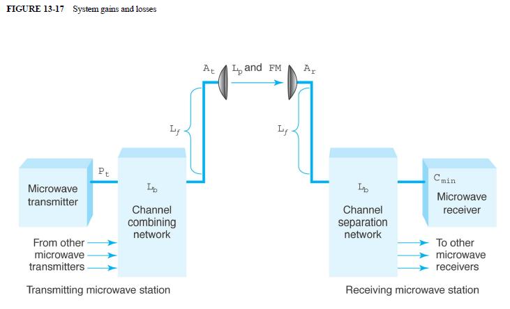
2 SYSTEM GAIN G s is the difference between the nominal output power of a transmitter (P t ) and the minimum input power to a receiver (C min ) necessary to achieve satisfactory performance; Must be greater than or equal to the sum of all gains and losses incurred by a signal as it propagates from a transmitter to a receiver In essence, system gain represents the net loss of a radio system, which is used to predict the reliability of a system for a given set of system parameters.
3 SYSTEM GAIN Ironically, system gain is actually a loss. Losses are much higher than the gains. Therefore, the net system gain always equates to a negative db value (i.e., a loss) Because system gain is defined as a net loss individual losses are represented with positive db individual gains are represented with negative db
4
5 Mathematically, system gain in its simplest form is G s = P t - C min where G s = system gain (db) P t = transmitter output power (dbm or dbw) C min = minimum receiver input power necessary to achieve a given reliability and quality objective
6 G s = P t - C min losses gains P t - C min FM (db) + L p(db) + L f(db) + Lb (db) - A t(db) - A r(db) Gains: A t = transmit antenna gain relative to an isotropic radiator (db) A r = receive antenna gain relative to an isotropic radiator (db) Losses FM = fade margin for a given reliability objective (db) L p = free-space path loss in (db) L f = transmission line loss in (db) L f = total coupling or branching loss in (db)

7 TABLE 13-3 System Gain Parameters
8 FADE MARGINS (LINK MARGIN)
9 FADING The reduction in receive signal level; Reduction in signal strength at the input to a receiver; It applies to propagation variables in the physical radio path that affect changes in the path loss between transmit and receive antennas
10 WHAT IS FADE MARGIN? Under interference-free conditions, the fade margin is defined as the difference between the received signal level under normal wave propagation conditions (fadefree time) and the receiver s threshold level at a given bit-error level Considers the non-ideal and less predictable characteristics of radiowave propagation, such as multipath propagation and terrain sensitivity; these characteristics cause temporary, abnormal atmospheric conditions
11 TYPES OF FADE MARGIN Thermal Fade Margin (TFM) Also called Flat Fade Margin Interference Fade Margin (IFM) Dispersive Fade Margin (DFM) Composite Fade Margin (CFM)
12 THERMAL OR FLAT FADE MARGIN The difference between the unfaded received signal level (RSL) and receiver s static or dynaminc threshold, as measured with back-to-back radios, at a given BER. Thermal Fade Margin is the only fade margin that needs to be considered on analog LOS links since interference affects unfaded baseband noise. Mathematically: TFL = Recieved Signal Level Reciever Threshold
13 INTERFERENCE FADE MARGIN Defines the digital link s vulnerability to cochannel and adjacent channel interferrence and is provided by the frequency search company based on the manufacturer s threshold-to-interference (T/I) curves and the interference ambiance. Based on congestion of systems within the path using the same band of frequencies. Taken from graphs from a specific location and varies over time.
14 DISPERSIVE FADE MARGIN Dependent on the type of equipment and modulation used. These are gains in the equipment which are factored in because of technical improvements on the system and how they improve the information signal itself It is determined by the type of modulation, the effectiveness of equalization employed in the receive path, and the multipath signal s delay time.
15 DISPERSIVE FADE MARGIN DFM is calculated based on the W-curves using computation DFM = 17.6 log 10 (S w /158.4) where
16 COMPOSITE FADE MARGIN This is the total of all fade margins Mathematically: CFM = TFM + DFM + IFM In decibels CFM = -10 log ( 10 -TFM/ IFM/ DFM/10 ) where TFM,IFM,DFM in decibell (db)
17 RECEIVER THRESHOLD (RECEIVER SENSITIVITY)
18 WHAT IS RECEIVER THRESHOLD? Receiver threshold means the lowest signal your receiver will pick up and still operate. When nearing threshold, radio will sound noisy with static, TV will show snow and your cell phone will show only one bar or drop out
19 RECEIVER THRESHOLD The receiver threshold is the minimum signal required for the demodulator to work at a specific error rate. Two thresholds are normally defined, one at a BER of 10^ 6 and the other at a BER of 10^ 3. The reason for this is the original cutoff for audio applications was 10^ 3, whereas it is generally considered data requires at least 10^ 6 for an acceptable throughput rate.
20 RECEIVER THRESHOLD Explaining the value 10^ 3,or the loss of frame synchronization point (2 ^10 5 for SDH/SONET), is the correct threshold to use from a performance objective perspective as it is related to the severely eroded second ratio (SESR) but the industry tends to use 10^ 6 due to the data concerns.
21 RECEIVER THRESHOLD The receiver threshold is dependent on the minimum S/N required at the receiver input, the noise figure of the receiver s front-end, and the background thermal noise (Pn) Pn = ktb where k - Boltzmann s constant ( ^ 23) T - temperature in Kelvin B - bandwidth of the receiver.
22 RECEIVER THRESHOLD In general, the receiver threshold considered depends both on the required output performance at base- band, and on the type of interference For linear modulation, such as AM and SSB, and any Gaussian interference, the relation between the SNR at the detector output and the (RF) C/Iratio is linear
23 RECEIVER THRESHOLD In non-linear modulation, such as phase modulation (PM) or frequency modulation (FM), the post-detection signal-to-noise ratio can be greatly enhanced as compared to baseband transmission or compared to linear modulation Typically, for FM signals, the threshold is in the range of 3 to 10 db. This threshold fundamentally limits the noise immunity of various types of non-linear modulation techniques
24 Table: Typical receiver thresholds below which a voice baseband signal becomes almost unintelligible. Source: Gosling FM 25 khz db FM 12.5 khz db SSB 5 khz heavy companding moderate companding no companding db db db
25 CARRIER-TO-NOISE VS SIGNAL-TO-NOISE RATIO
26 CARRIER-TO-NOISE RATIO In communications, the carrier-to-noise ratio, often written CNR or C/N, is a measure of the received carrier strength relative to the strength of the received noise. High C/N ratios provide better quality of reception, and generally higher communications accuracy and reliability, than low C/N ratios. Carrier to noise ratio is the ratio of the carrier signal power to the noise power in some specified channel, usually expressed in decibels (db). For the analog channels the noise is assumed flat and the result of thermal and amplifier noises.
27 CARRIER-TO-NOISE RATIO (MATHEMATICAL DEFINITION) Engineers specify the C/N ratio in decibels (db) between the power in the carrier of the desired signal and the total received noise power. If the incoming carrier strength in microwatts is P c and the noise level, also in microwatts, is P n, then the carrier-to-noise ratio, C/N, in decibels is given by the formula: C/N = 10 log 10 (P c /P n )
28 CARRIER-TO-NOISE RATIO The C/N ratio is measured in a manner similar to the way the signal-to noise ratio (S/N) is measured, and both specifications give an indication of the quality of a communications channel. However, the S/N ratio specification is more meaningful in practical situations. The C/N ratio is commonly used in satellite communications systems to point or align the receiving dish; the best dish alignment is indicated by the maximum C/N ratio.
29 CARRIER-TO-NOISE RATIO Graphical representaion of C/N ratio (
30 SIGNAL-TO-NOISE RATIO In analog and digital communications, signal-to-noise ratio, often written S/N or SNR, is a measure of signal strength relative to background noise. The ratio is usually measured in decibels (db). Signal-to-noise ratio, or SNR, is a measurement that describes how much noise is in the output of a device, in relation to the signal level. SNR is actually two level measurements, followed by a simple calculation. First, we measure the output level of the device under test with no input signal. Then we apply a signal to the device and take another level measurement. Then we divide.
31 SIGNAL-TO-NOISE RATIO (MATHEMATICAL APPROACH) If the incoming signal strength in microvolts is V s, and the noise level, also in microvolts, is V n, then the signal-to-noise ratio, S/N, in decibels is given by the formula: S/N = 20 log 10 (V s /V n )

32 SIGNAL-TO-NOISE RATIO Graphical representation of SNR propagation ( l)
33 CNR VS. SNR RECAP CNR is a predetection measurement performed on RF signals. Raw carrier power to raw noise power in the RF transport path only say, a coaxial cable distribution network or a standalone device such as a converter or headend hetrodyne processor; Ideal for characterizing network impairments
34 CNR VS. SNR RECAP SNR is a pre modulation or post-detection measurement performed on baseband signals. Includes noise in original signal, transmitter or modulator, transport path, and reciever and demodulator Ideal for characterizing end-to-end performance the overall signal quality seen by the end user
35 NOISE FACTOR AND NOISE FIGURE
36 WHAT IS NOISE FACTOR? Simply a ratio of input signal-to-noise ratio to output signal-to-noise ratio Any unwanted input Limits systems ability to process weak signals Sources: 1. Random noise in resistors and transistors 2. Mixer noise 3. Undesired cross-coupling noise 4. Power supply noise Dynamic range capability of detecting weak signals in presence of large-amplitude signals
37 NOISE FACTOR IEEE Standards: The noise factor, at a specified input frequency, is defined as the ratio of (1) the total noise power per unit bandwidth available at the output port when noise temperature of the input termination is standard (290 K) to (2) that portion of (1) engendered at the input frequency by the input termination. F = available output noise power available output noise due to source
38 NOISE FACTOR noisiness of the signal measure = signal-to-noise ratio (frequency dependant) SNR = S( f N( f ) ) = average signal power average noise power
39 NOISE FACTOR The noise factor F of a system is defined as: F = (SNR in )/(SNR out ) where SNR in = input signal-to-noise power ratio SNR out = output signal-to-noise power ratio
40 WHAT IS NOISE FIGURE? Indicates how much the signal-to-noise ratio deteriorates as a waveform propagates from the input of a circuit It is a measure of the degradation of SNR due to the SNRi noise added F = 1 SNRo Implies that SNR gets worse as we process the signal Na Spot noise factor F =1+ kt The answer is the bandwidth
41 NOISE FIGURE The noise figure NF is defined as: The noise figure is the factor, given in db

42 NOISE FIGURE IN TEMPERATURE(K)
43 THANK YOU! PENTEL.COM
Noise and Interference Limited Systems
 Chapter 3 Noise and Interference Limited Systems 47 Basics of link budgets Link budgets show how different components and propagation processes influence the available SNR Link budgets can be used to compute
Chapter 1: Introduction. EET-223: RF Communication Circuits Walter Lara
 Chapter 1: Introduction EET-223: RF Communication Circuits Walter Lara Introduction Electronic communication involves transmission over medium from source to destination Information can contain voice,
Antennas and Propagation. Chapter 5
 Antennas and Propagation Chapter 5 Introduction An antenna is an electrical conductor or system of conductors Transmission - radiates electromagnetic energy into space Reception - collects electromagnetic
Antennas and Propagation. Chapter 5
 Antennas and Propagation Chapter 5 Introduction An antenna is an electrical conductor or system of conductors Transmission - radiates electromagnetic energy into space Reception - collects electromagnetic
Antennas and Propagation
 Antennas and Propagation Chapter 5 Introduction An antenna is an electrical conductor or system of conductors Transmission - radiates electromagnetic energy into space Reception - collects electromagnetic
MULTI-CHANNEL CARS BAND DISTRIBUTION USING STANDARD FM MICROWAVE EQUIPMENT. Presented By
 608 MULTI-CHANNEL CARS BAND DISTRIBUTION USING STANDARD FM MICROWAVE EQUIPMENT Presented By Terry R. Spearen, Manager of Systems Engineering Communication Equipment Division MICROWAVE ASSOCIATES, INC.
Antennas and Propagation
 Mobile Networks Module D-1 Antennas and Propagation 1. Introduction 2. Propagation modes 3. Line-of-sight transmission 4. Fading Slides adapted from Stallings, Wireless Communications & Networks, Second
Antennas and Propagation
 CMPE 477 Wireless and Mobile Networks Lecture 3: Antennas and Propagation Antennas Propagation Modes Line of Sight Transmission Fading in the Mobile Environment Introduction An antenna is an electrical
CHAPTER 3 Noise in Amplitude Modulation Systems
 CHAPTER 3 Noise in Amplitude Modulation Systems NOISE Review: Types of Noise External (Atmospheric(sky),Solar(Cosmic),Hotspot) Internal(Shot, Thermal) Parameters of Noise o Signal to Noise ratio o Noise
Antennas & Propagation. CSG 250 Fall 2007 Rajmohan Rajaraman
 Antennas & Propagation CSG 250 Fall 2007 Rajmohan Rajaraman Introduction An antenna is an electrical conductor or system of conductors o Transmission - radiates electromagnetic energy into space o Reception
RADIO RECEIVERS ECE 3103 WIRELESS COMMUNICATION SYSTEMS
 RADIO RECEIVERS ECE 3103 WIRELESS COMMUNICATION SYSTEMS FUNCTIONS OF A RADIO RECEIVER The main functions of a radio receiver are: 1. To intercept the RF signal by using the receiver antenna 2. Select the
Coverage Impact of Implementing Narrowband Equipment. Bernie Olson Chair TIA TR8.18
 Coverage Impact of Implementing Narrowband Equipment Bernie Olson Chair TIA TR8.18 It Depends ON Lots of variables to take into consideration Migration process Link Budget Tradeoff of sensitivity and interference
Session2 Antennas and Propagation
 Wireless Communication Presented by Dr. Mahmoud Daneshvar Session2 Antennas and Propagation 1. Introduction Types of Anttenas Free space Propagation 2. Propagation modes 3. Transmission Problems 4. Fading
Making Noise in RF Receivers Simulate Real-World Signals with Signal Generators
 Making Noise in RF Receivers Simulate Real-World Signals with Signal Generators Noise is an unwanted signal. In communication systems, noise affects both transmitter and receiver performance. It degrades
THE BASICS OF RADIO SYSTEM DESIGN
 THE BASICS OF RADIO SYSTEM DESIGN Mark Hunter * Abstract This paper is intended to give an overview of the design of radio transceivers to the engineer new to the field. It is shown how the requirements
Chapter-15. Communication systems -1 mark Questions
 Chapter-15 Communication systems -1 mark Questions 1) What are the three main units of a Communication System? 2) What is meant by Bandwidth of transmission? 3) What is a transducer? Give an example. 4)
Technician License Course Chapter 3 Types of Radios and Radio Circuits. Module 7
 Technician License Course Chapter 3 Types of Radios and Radio Circuits Module 7 Radio Block Diagrams Radio Circuits can be shown as functional blocks connected together. Knowing the description of common
The Friis Transmission Formula
 The Friis Transmission Formula If we assume that the antennas are aligned for maximum transmission and reception, then in free space, P RX = G TXA e P TX 4πr 2 where A e is the receiving aperture of the
Frequency Modulation
 Frequency Modulation transferred to the microwave carrier by means of FM. Instead of being done in one step, this modulation usually takes place at an intermediate frequency. signal is then frequency multiplied
Noise by the Numbers
 Noise by the Numbers 1 What can I do with noise? The two primary applications for white noise are signal jamming/impairment and reference level comparison. Signal jamming/impairment is further divided
NXDN Signal and Interference Contour Requirements An Empirical Study
 NXDN Signal and Interference Contour Requirements An Empirical Study Icom America Engineering December 2007 Contents Introduction Results Analysis Appendix A. Test Equipment Appendix B. Test Methodology
ECE 630: Statistical Communication Theory
 ECE 630: Statistical Communication Theory Dr. B.-P. Paris Dept. Electrical and Comp. Engineering George Mason University Last updated: January 23, 2018 2018, B.-P. Paris ECE 630: Statistical Communication
C/I = log δ 3 log (i/10)
") Rec. ITU-R S.61-3 1 RECOMMENDATION ITU-R S.61-3 NECESSARY PROTECTION RATIOS FOR NARROW-BAND SINGLE CHANNEL-PER-CARRIER TRANSMISSIONS INTERFERED WITH BY ANALOGUE TELEVISION CARRIERS (Question ITU-R 50/4)
Rec. ITU-R S.61-3 1 RECOMMENDATION ITU-R S.61-3 NECESSARY PROTECTION RATIOS FOR NARROW-BAND SINGLE CHANNEL-PER-CARRIER TRANSMISSIONS INTERFERED WITH BY ANALOGUE TELEVISION CARRIERS (Question ITU-R 50/4)
TSEK02: Radio Electronics Lecture 6: Propagation and Noise. Ted Johansson, EKS, ISY
 TSEK02: Radio Electronics Lecture 6: Propagation and Noise Ted Johansson, EKS, ISY 2 Propagation and Noise - Channel and antenna: not in the Razavi book - Noise: 2.3 The wireless channel The antenna Signal
High Dynamic Range Receiver Parameters
 High Dynamic Range Receiver Parameters The concept of a high-dynamic-range receiver implies more than an ability to detect, with low distortion, desired signals differing, in amplitude by as much as 90
Module 8 Theory. dbs AM Detector Ring Modulator Receiver Chain. Functional Blocks Parameters. IRTS Region 4
 Module 8 Theory dbs AM Detector Ring Modulator Receiver Chain Functional Blocks Parameters Decibel (db) The term db or decibel is a relative unit of measurement used frequently in electronic communications
Lecture 6 SIGNAL PROCESSING. Radar Signal Processing Dr. Aamer Iqbal Bhatti. Dr. Aamer Iqbal Bhatti
 Lecture 6 SIGNAL PROCESSING Signal Reception Receiver Bandwidth Pulse Shape Power Relation Beam Width Pulse Repetition Frequency Antenna Gain Radar Cross Section of Target. Signal-to-noise ratio Receiver
Exercise 1: RF Stage, Mixer, and IF Filter
 SSB Reception Analog Communications Exercise 1: RF Stage, Mixer, and IF Filter EXERCISE OBJECTIVE DISCUSSION On the circuit board, you will set up the SSB transmitter to transmit a 1000 khz SSB signal
CSE 561 Bits and Links. David Wetherall
 CSE 561 Bits and Links David Wetherall djw@cs.washington.edu Topic How do we send a message across a wire? The physical/link layers: 1. Different kinds of media 2. Encoding bits 3. Model of a link Application
Satellite Link Budget Calculator by Using Matlab/GUI
 A Special Issue for 2nd International Conference of Cihan University-Erbil on Communication Engineering & Computer Sciences (CIC-COCOS 17), March 29-30, 2017 Satellite Link Budget Calculator by Using Matlab/GUI
RF/IF Terminology and Specs
 RF/IF Terminology and Specs Contributors: Brad Brannon John Greichen Leo McHugh Eamon Nash Eberhard Brunner 1 Terminology LNA - Low-Noise Amplifier. A specialized amplifier to boost the very small received
CHAPTER 6 THE WIRELESS CHANNEL
 CHAPTER 6 THE WIRELESS CHANNEL These slides are made available to faculty in PowerPoint form. Slides can be freely added, modified, and deleted to suit student needs. They represent substantial work on
Introduction to Analog And Digital Communications
 Introduction to Analog And Digital Communications Second Edition Simon Haykin, Michael Moher Chapter 11 System and Noise Calculations 11.1 Electrical Noise 11.2 Noise Figure 11.3 Equivalent Noise Temperature
Mobile and Wireless Networks Course Instructor: Dr. Safdar Ali
 Mobile and Wireless Networks Course Instructor: Dr. Safdar Ali BOOKS Text Book: William Stallings, Wireless Communications and Networks, Pearson Hall, 2002. BOOKS Reference Books: Sumit Kasera, Nishit
Code No: R Set No. 1
 Code No: R05220405 Set No. 1 II B.Tech II Semester Regular Examinations, Apr/May 2007 ANALOG COMMUNICATIONS ( Common to Electronics & Communication Engineering and Electronics & Telematics) Time: 3 hours
Microwave Seminar. Noise and Bit Error Ratio. J. Richie. Spring 2013
 Microwave Seminar Noise and Bit Error Ratio J. Richie Spring 2013 Outline Noise Noise and Equivalent Temperature Noise Figure Small Scale Fade and Multipath Impulse Response Model Types of Fading Modulation
Spacecraft Communications
 Antennas Orbits Modulation Noise Link Budgets 1 2012 David L. Akin - All rights reserved http://spacecraft.ssl.umd.edu The Problem Pointing Loss Polarization Loss Atmospheric Loss, Rain Loss Space Loss
TSEK02: Radio Electronics Lecture 6: Propagation and Noise. Ted Johansson, EKS, ISY
 TSEK02: Radio Electronics Lecture 6: Propagation and Noise Ted Johansson, EKS, ISY 2 Propagation and Noise - Channel and antenna: not in the Razavi book - Noise: 2.3 The wireless channel The antenna Signal
Effects of multipath propagation on design and operation of line-of-sight digital radio-relay systems
 Rec. ITU-R F.1093-1 1 RECOMMENDATION ITU-R F.1093-1* Rec. ITU-R F.1093-1 EFFECTS OF MULTIPATH PROPAGATION ON THE DESIGN AND OPERATION OF LINE-OF-SIGHT DIGITAL RADIO-RELAY SYSTEMS (Question ITU-R 122/9)
MAHALAKSHMI ENGINEERING COLLEGE-TRICHY QUESTION BANK UNIT IV PART-A
 MAHALAKSHMI ENGINEERING COLLEGE-TRICHY QUESTION BANK SATELLITE COMMUNICATION DEPT./SEM.:ECE/VIII UNIT IV PART-A 1. What are the advantages of the super heterodyne receiver over TRF receiver? (AUC MAY 2004)
REPORT ITU-R BT TERRESTRIAL TELEVISION BROADCASTING IN BANDS ABOVE 2 GHZ (Questions ITU-R 1/11 and ITU-R 49/11)
") - 1 - REPORT ITU-R BT.961-2 TERRESTRIAL TELEVISION BROADCASTING IN BANDS ABOVE 2 GHZ (Questions ITU-R 1/11 and ITU-R 49/11) (1982-1986-1994) 1. Introduction Experimental amplitude-modulation terrestrial
- 1 - REPORT ITU-R BT.961-2 TERRESTRIAL TELEVISION BROADCASTING IN BANDS ABOVE 2 GHZ (Questions ITU-R 1/11 and ITU-R 49/11) (1982-1986-1994) 1. Introduction Experimental amplitude-modulation terrestrial
Adjacent Channel Studies in the FM Band
 Adjacent Channel Studies in the FM Band Prepared for the NRSC By ibiquity Digital Corporation 11/09/00 Adjacent Channel Studies in the FM Band Page 1 As part of its AM IBOC development effort, ibiquity
COMMUNICATION SYSTEMS -I
 COMMUNICATION SYSTEMS -I Communication : It is the act of transmission of information. ELEMENTS OF A COMMUNICATION SYSTEM TRANSMITTER MEDIUM/CHANNEL: The physical medium that connects transmitter to receiver
TSEK02: Radio Electronics Lecture 8: RX Nonlinearity Issues, Demodulation. Ted Johansson, EKS, ISY
 TSEK02: Radio Electronics Lecture 8: RX Nonlinearity Issues, Demodulation Ted Johansson, EKS, ISY RX Nonlinearity Issues: 2.2, 2.4 Demodulation: not in the book 2 RX nonlinearities System Nonlinearity
HY448 Sample Problems
 HY448 Sample Problems 10 November 2014 These sample problems include the material in the lectures and the guided lab exercises. 1 Part 1 1.1 Combining logarithmic quantities A carrier signal with power
Outline / Wireless Networks and Applications Lecture 3: Physical Layer Signals, Modulation, Multiplexing. Cartoon View 1 A Wave of Energy
 Outline 18-452/18-750 Wireless Networks and Applications Lecture 3: Physical Layer Signals, Modulation, Multiplexing Peter Steenkiste Carnegie Mellon University Spring Semester 2017 http://www.cs.cmu.edu/~prs/wirelesss17/
Satellite Link Budget Calculator by Using Matlab/GUI
 CIC-COCOS 7 March 29-30, 207, Cihan University-Erbil Satellite Link Budget Calculator by Using Matlab/GUI Adil Hussein M. Al-Dalowi Communication and Computer Engineering Department Adil.mohanned@cihanuniversity.edu.iq
Receiver Design. Prof. Tzong-Lin Wu EMC Laboratory Department of Electrical Engineering National Taiwan University 2011/2/21
 Receiver Design Prof. Tzong-Lin Wu EMC Laboratory Department of Electrical Engineering National Taiwan University 2011/2/21 MW & RF Design / Prof. T. -L. Wu 1 The receiver mush be very sensitive to -110dBm
SATELLITE LINK DESIGN
 1 SATELLITE LINK DESIGN Networks and Communication Department Dr. Marwah Ahmed Outlines 2 Introduction Basic Transmission Theory System Noise Temperature and G/T Ratio Design of Downlinks Satellite Communication
INTRODUCTION TO COMMUNICATION SYSTEMS AND TRANSMISSION MEDIA
 COMM.ENG INTRODUCTION TO COMMUNICATION SYSTEMS AND TRANSMISSION MEDIA 9/9/2017 LECTURES 1 Objectives To give a background on Communication system components and channels (media) A distinction between analogue
PRINCIPLES OF COMMUNICATION SYSTEMS. Lecture 1- Introduction Elements, Modulation, Demodulation, Frequency Spectrum
 PRINCIPLES OF COMMUNICATION SYSTEMS Lecture 1- Introduction Elements, Modulation, Demodulation, Frequency Spectrum Topic covered Introduction to subject Elements of Communication system Modulation General
ENGR 4323/5323 Digital and Analog Communication
 ENGR 4323/5323 Digital and Analog Communication Chapter 1 Introduction Engineering and Physics University of Central Oklahoma Dr. Mohamed Bingabr Course Materials Textbook: Modern Digital and Analog Communication,
Adoption of this document as basis for broadband wireless access PHY
 Project Title Date Submitted IEEE 802.16 Broadband Wireless Access Working Group Proposal on modulation methods for PHY of FWA 1999-10-29 Source Jay Bao and Partha De Mitsubishi Electric ITA 571 Central
RF Board Design. EEC 134 Application Note. Jo Han Yu
 EEC 134 Application Note Jo Han Yu EEC 134 Application Note RF Board Design Introduction The objective of this application note is to outline the process of designing system and PCB layout for RF board
Transmission Impairments
 1/13 Transmission Impairments Surasak Sanguanpong nguan@ku.ac.th http://www.cpe.ku.ac.th/~nguan Last updated: 11 July 2000 Transmissions Impairments 1/13 Type of impairments 2/13 Attenuation Delay distortion
two computers. 2- Providing a channel between them for transmitting and receiving the signals through it.
 1. Introduction: Communication is the process of transmitting the messages that carrying information, where the two computers can be communicated with each other if the two conditions are available: 1-
Data and Computer Communications. Chapter 3 Data Transmission
 Data and Computer Communications Chapter 3 Data Transmission Data Transmission quality of the signal being transmitted The successful transmission of data depends on two factors: characteristics of the
Chapter 3. Question Mar No
 Chapter 3 Sr Question Mar No k. 1 Write any two drawbacks of TRF radio receiver 1. Instability due to oscillatory nature of RF amplifier.. Variation in bandwidth over tuning range. 3. Insufficient selectivity
Module 10 : Receiver Noise and Bit Error Ratio
 Module 10 : Receiver Noise and Bit Error Ratio Lecture : Receiver Noise and Bit Error Ratio Objectives In this lecture you will learn the following Receiver Noise and Bit Error Ratio Shot Noise Thermal
Estimation of Predetection SNR of LMR Analog FM Signals Using PL Tone Analysis
 Estimation of Predetection SNR of LMR Analog FM Signals Using PL Tone Analysis Akshay Kumar akshay2@vt.edu Steven Ellingson ellingson@vt.edu Virginia Tech, Wireless@VT May 2, 2012 Table of Contents 1 Introduction
Course 2: Channels 1 1
 Course 2: Channels 1 1 "You see, wire telegraph is a kind of a very, very long cat. You pull his tail in New York and his head is meowing in Los Angeles. Do you understand this? And radio operates exactly
Understanding Noise Figure
 Understanding Noise Figure Iulian Rosu, YO3DAC / VA3IUL, http://www.qsl.net/va3iul One of the most frequently discussed forms of noise is known as Thermal Noise. Thermal noise is a random fluctuation in
AM and FM MODULATION Lecture 5&6
 AM and FM MODULATION Lecture 5&6 Ir. Muhamad Asvial, MEng., PhD Center for Information and Communication Engineering Research Electrical Engineering Department University of Indonesia Kampus UI Depok,
Satellite Signals and Communications Principles. Dr. Ugur GUVEN Aerospace Engineer (P.hD)
") Satellite Signals and Communications Principles Dr. Ugur GUVEN Aerospace Engineer (P.hD) Principle of Satellite Signals In essence, satellite signals are electromagnetic waves that travel from the satellite
Satellite Signals and Communications Principles Dr. Ugur GUVEN Aerospace Engineer (P.hD) Principle of Satellite Signals In essence, satellite signals are electromagnetic waves that travel from the satellite
Introduction to Receivers
 Introduction to Receivers Purpose: translate RF signals to baseband Shift frequency Amplify Filter Demodulate Why is this a challenge? Interference Large dynamic range required Many receivers must be capable
Contents. Telecom Service Chae Y. Lee. Data Signal Transmission Transmission Impairments Channel Capacity
 Data Transmission Contents Data Signal Transmission Transmission Impairments Channel Capacity 2 Data/Signal/Transmission Data: entities that convey meaning or information Signal: electric or electromagnetic
Modulation Methods Frequency Modulation
 Modulation Methods Frequency Modulation William Sheets K2MQJ Rudolf F. Graf KA2CWL The use of frequency modulation (called FM) is another method of adding intelligence to a carrier signal. While simple
A DISCUSSION ON QAM SNARE SENSITIVITY
 ADVANCED TECHNOLOGY A DISCUSSION ON QAM SNARE SENSITIVITY HOW PROCESSING GAIN DELIVERS BEST SENSITIVITY IN THE CATEGORY 185 AINSLEY DRIVE SYRACUSE, NY 13210 800.448.1655 / WWW.ARCOMDIGITAL.COM ADVANCED
Understanding the performance of atmospheric free-space laser communications systems using coherent detection
 !"#$%&'()*+&, Understanding the performance of atmospheric free-space laser communications systems using coherent detection Aniceto Belmonte Technical University of Catalonia, Department of Signal Theory
Introduction to Telecommunications and Computer Engineering Unit 3: Communications Systems & Signals
 Introduction to Telecommunications and Computer Engineering Unit 3: Communications Systems & Signals Syedur Rahman Lecturer, CSE Department North South University syedur.rahman@wolfson.oxon.org Acknowledgements
Physical Layer: Outline
 18-345: Introduction to Telecommunication Networks Lectures 3: Physical Layer Peter Steenkiste Spring 2015 www.cs.cmu.edu/~prs/nets-ece Physical Layer: Outline Digital networking Modulation Characterization
Noise in a DVB-T System
 Noise in a DVB-T System John Salter Summary This note was written to clarify a simple theoretical noise model of a DVB-T system described in [Reference 1]. This model gives the system carrier-to-noise
CHAPTER -15. Communication Systems
 CHAPTER -15 Communication Systems COMMUNICATION Communication is the act of transmission and reception of information. COMMUNICATION SYSTEM: A system comprises of transmitter, communication channel and
TECH BRIEF Addressing Phase Noise Challenges in Radar and Communication Systems
 Addressing Phase Noise Challenges in Radar and Communication Systems Phase noise is rapidly becoming the most critical factor addressed in sophisticated radar and communication systems. This is because
Lecture Fundamentals of Data and signals
 IT-5301-3 Data Communications and Computer Networks Lecture 05-07 Fundamentals of Data and signals Lecture 05 - Roadmap Analog and Digital Data Analog Signals, Digital Signals Periodic and Aperiodic Signals
15.Calculate the local oscillator frequency if incoming frequency is F1 and translated carrier frequency
 DEPARTMENT OF ELECTRONICS & COMMUNICATION ENGINEERING SUBJECT NAME:COMMUNICATION THEORY YEAR/SEM: II/IV SUBJECT CODE: EC 6402 UNIT I:l (AMPLITUDE MODULATION) PART A 1. Compute the bandwidth of the AMP
Modern radio techniques
 Modern radio techniques for probing the ionosphere Receiver, radar, advanced ionospheric sounder, and related techniques Cesidio Bianchi INGV - Roma Italy Ionospheric properties related to radio waves
Satellite System Parameters
 Satellite System Parameters Lecture 3 MUHAMAD ASVIAL Center for Information and Communication Engineering Research (CICER) Electrical Engineering Department, University of Indonesia Kampus UI Depok, 16424,
TSEK02: Radio Electronics Lecture 8: RX Nonlinearity Issues, Demodulation. Ted Johansson, EKS, ISY
 TSEK02: Radio Electronics Lecture 8: RX Nonlinearity Issues, Demodulation Ted Johansson, EKS, ISY 2 RX Nonlinearity Issues, Demodulation RX nonlinearities (parts of 2.2) System Nonlinearity Sensitivity
Optical Single Sideband Modulation and Optical Carrier Power Reduction and CATV Networks
 Optical Single Sideband Modulation and Optical Carrier Power Reduction and CATV Networks by: Hatice Kosek Outline Optical Single Sideband Modulation Techniques Optical Carrier Power Reduction Techniques
UNIT I AMPLITUDE MODULATION
 UNIT I AMPLITUDE MODULATION Prepared by: S.NANDHINI, Assistant Professor, Dept. of ECE, Sri Venkateswara College of Engineering, Sriperumbudur, Tamilnadu. CONTENTS Introduction to communication systems
RECOMMENDATION ITU-R BS
 Rec. ITU-R BS.1194-1 1 RECOMMENDATION ITU-R BS.1194-1 SYSTEM FOR MULTIPLEXING FREQUENCY MODULATION (FM) SOUND BROADCASTS WITH A SUB-CARRIER DATA CHANNEL HAVING A RELATIVELY LARGE TRANSMISSION CAPACITY
Lecture 3: Data Transmission
 Lecture 3: Data Transmission 1 st semester 1439-2017 1 By: Elham Sunbu OUTLINE Data Transmission DATA RATE LIMITS Transmission Impairments Examples DATA TRANSMISSION The successful transmission of data
Noise and Distortion in Microwave System
 Noise and Distortion in Microwave System Prof. Tzong-Lin Wu EMC Laboratory Department of Electrical Engineering National Taiwan University 1 Introduction Noise is a random process from many sources: thermal,
Adapted from Dr. Joe Montana (George mason University) Dr. James
 Dr. James") ink Budget Adapted from Dr. Joe Montana (George mason University) Dr. James W. apean course notes Dr. Jeremy Allnutt course notes And some internet resources + Tim Pratt book 1 ink Power Budget Tx EIRP
ink Budget Adapted from Dr. Joe Montana (George mason University) Dr. James W. apean course notes Dr. Jeremy Allnutt course notes And some internet resources + Tim Pratt book 1 ink Power Budget Tx EIRP
Application of a Telemetry System using DSB-AM Sub-Carriers
 Application of a Telemetry System using DSB-AM Sub-Carriers Item Type text; Proceedings Authors Roche, A. O. Publisher International Foundation for Telemetering Journal International Telemetering Conference
Announcements : Wireless Networks Lecture 3: Physical Layer. Bird s Eye View. Outline. Page 1
 Announcements 18-759: Wireless Networks Lecture 3: Physical Layer Please start to form project teams» Updated project handout is available on the web site Also start to form teams for surveys» Send mail
Fundament Fundamen als t of Communications
 Fundamentals of Communications Communication System Transmitter Medium Receiver Transmitter: originates the signal Receiver: receives transmitted signal after it travels over the medium Medium: guides
 UNIT I FUNDAMENTALS OF ANALOG COMMUNICATION Introduction In the Microbroadcasting services, a reliable radio communication system is of vital importance. The swiftly moving operations of modern communities
Lecture 2 Physical Layer - Data Transmission
 DATA AND COMPUTER COMMUNICATIONS Lecture 2 Physical Layer - Data Transmission Mei Yang Based on Lecture slides by William Stallings 1 DATA TRANSMISSION The successful transmission of data depends on two
ESPTR (English) Signal Processing in Telecommunications and Radar Channel properties
 Signal Processing in Telecommunications and Radar Channel properties") ESPTR (English) Signal Processing in Telecommunications and Radar Channel properties Jacek Misiurewicz e-mail: jmisiure@elka.pw.edu.pl Institute of Electronic Systems Warsaw University of Technology Warsaw,
ESPTR (English) Signal Processing in Telecommunications and Radar Channel properties Jacek Misiurewicz e-mail: jmisiure@elka.pw.edu.pl Institute of Electronic Systems Warsaw University of Technology Warsaw,
Contents. ITS323: Introduction to Data Communications CSS331: Fundamentals of Data Communications. Transmission Media and Spectrum.
 2 ITS323: Introduction to Data Communications CSS331: Fundamentals of Data Communications Sirindhorn International Institute of Technology Thammasat University Prepared by Steven Gordon on 3 August 2015
ITS323: Introduction to Data Communications CSS331: Fundamentals of Data Communications
 ITS323: Introduction to Data Communications CSS331: Fundamentals of Data Communications Sirindhorn International Institute of Technology Thammasat University Prepared by Steven Gordon on 3 August 2015
Chapter 2 Channel Equalization
 Chapter 2 Channel Equalization 2.1 Introduction In wireless communication systems signal experiences distortion due to fading [17]. As signal propagates, it follows multiple paths between transmitter and
Receiver Design for Passive Millimeter Wave (PMMW) Imaging
 Imaging") Introduction Receiver Design for Passive Millimeter Wave (PMMW) Imaging Millimeter Wave Systems, LLC Passive Millimeter Wave (PMMW) sensors are used for remote sensing and security applications. They rely
Introduction Receiver Design for Passive Millimeter Wave (PMMW) Imaging Millimeter Wave Systems, LLC Passive Millimeter Wave (PMMW) sensors are used for remote sensing and security applications. They rely
HF Receivers, Part 2
 HF Receivers, Part 2 Superhet building blocks: AM, SSB/CW, FM receivers Adam Farson VA7OJ View an excellent tutorial on receivers NSARC HF Operators HF Receivers 2 1 The RF Amplifier (Preamp)! Typical
PULSE CODE MODULATION TELEMETRY Properties of Various Binary Modulation Types
 PULSE CODE MODULATION TELEMETRY Properties of Various Binary Modulation Types Eugene L. Law Telemetry Engineer Code 1171 Pacific Missile Test Center Point Mugu, CA 93042 ABSTRACT This paper discusses the
UNIVERSITI MALAYSIA PERLIS Pusat Pengajian Kejuruteraan Komputer dan Perhubungan Semester 1, 2011/12 DKT 211 Basic Communication Engineering
 UNIVERSITI MALAYSIA PERLIS Pusat Pengajian Kejuruteraan Komputer dan Perhubungan Semester 1, 2011/12 DKT 211 Basic Communication Engineering TUTORIAL 1: NOISE AND TRANSMISSION MEDIA & EM TUTORIAL 1 CHAPTER
Some Aspects Regarding the Measurement of the Adjacent Channel Interference for Frequency Hopping Radio Systems
 Some Aspects Regarding the Measurement of the Adjacent Channel Interference for Frequency Hopping Radio Systems PAUL BECHET, RADU MITRAN, IULIAN BOULEANU, MIRCEA BORA Communications and Information Systems
Elements of Communication System Channel Fig: 1: Block Diagram of Communication System Terminology in Communication System
 Content:- Fundamentals of Communication Engineering : Elements of a Communication System, Need of modulation, electromagnetic spectrum and typical applications, Unit V (Communication terminologies in communication