EENG473 Mobile Communications Module 3 : Week # (12) Mobile Radio Propagation: Small-Scale Path Loss
|
|
|
- Everett Stone
- 6 years ago
- Views:
Transcription
1 EENG473 Mobile Communications Module 3 : Week # (12) Mobile Radio Propagation: Small-Scale Path Loss
2 Introduction Small-scale fading is used to describe the rapid fluctuation of the amplitude of a radio signal over a short period of time or travel distance. Fading is caused by interference between two or more versions of the transmitted signal which arrive at the receiver at slightly different times. Multipath waves consists of a large number of plane waves having randomly distributed amplitudes, phases, and angles of arrival. that causes the signal to distort or fade.
3 Small-Scale Multipath Propagation Multipath creates small-scale fading effects such as: 1. Rapid changes in signal strength over a small travel distance or time interval 2. Random frequency modulation due to varying Doppler shifts on different multipath signals. 3. Time dispersion caused by multipath propagation delays.
4
5 The Doppler shift The shift in received signal frequency due to motion is directly proportional to the velocity and direction of motion of the mobile with respect to the direction of arrival of the received multipath wave.
6 Illustration of Doppler effect
7 Doppler Shift The equation relates the Doppler shift to the mobile velocity and the spatial angle between the direction of motion of the mobile and the direction of arrival of the wave.
8 The Doppler shift is positive (i.e., the apparent received frequency is increased), if the mobile is moving toward the direction of arrival of the wave. The Doppler shift is negative (i.e. the apparent received frequency is decreased), if the mobile is moving away from the direction of arrival of the wave. multipath components from a CW signal which arrive from different directions contribute to Doppler spreading of the received signal, thus increasing the signal bandwidth.
9
10
11
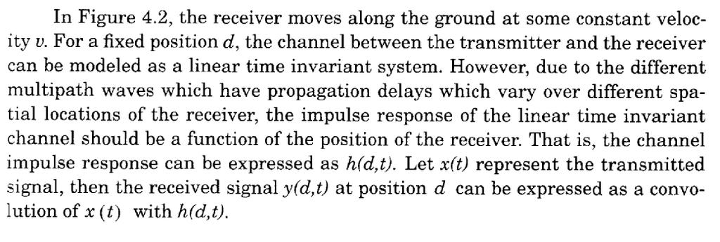
12 4.2 Impulse Response Model of a Multipath Channel To show that a mobile radio channel may be modeled as a linear filter with a time varying impulse response, consider the case where time variation is due strictly to receiver motion in space.
13
14
15
16
17
18
19
20
21
22
23 Power Delay Profile
24
25 4.4 Parameters of Mobile Multipath Channels Many multipath channel parameters are derived from the power delay profile. Depending on the time resolution of the probing pulse and the type of multipath channels studied, researchers often choose to sample at spatial separations of a quarter of a wavelength and over receiver movements no greater than 6 m in outdoor channels and no greater than 2 m in indoor channels in the 450 MHz - 6 GHz range. This small-scale sampling avoids averaging bias in the resulting small-scale statistics. Figure 4.9 shows typical power delay profile plots from outdoor and indoor channels, determined from a large number of closely sampled instantaneous profiles.
26
27
28
29 Timer Dispersion Parameters τ ( ) = = = k k k k k k k k k k P P a a ) ( ) )( ( τ τ τ τ τ τ τ σ τ Determined from a power delay profile. Mean excess delay( ): Rms delay spread (s t ): = = k k k k k k k k k k P P a a ) ( ) )( ( 2 2 τ τ τ τ τ
30
31 Table 4.1 shows the typical measured values of rms delay spread. Typical values of rms delay spread are on the order of microseconds in outdoor mobile radio channels and on the order of nanoseconds in indoor radio channels. It is important to note that the rms delay spread and mean excess delay are defined from a single power delay profile which is the temporal or spatial average of consecutive impulse response measurements collected and averaged over a local area.
32
33
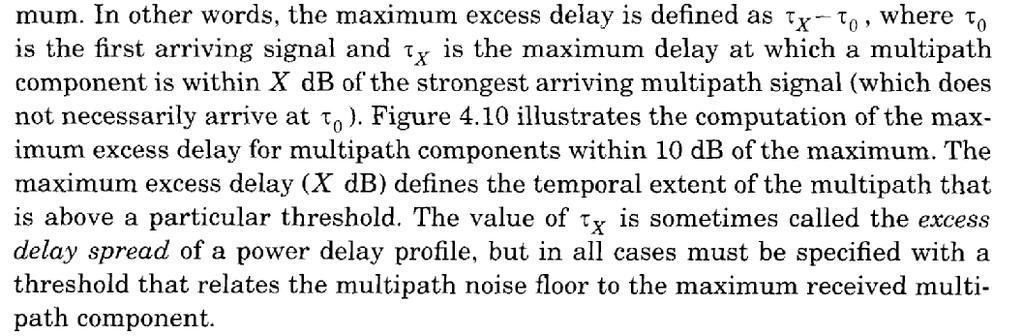
34 Power delay Profile -90 RMS Delay Spread ( ) = 46.4 ns Received Signal Level (dbm) Mean Excess delay ( ) = 45 ns Maximum Excess delay < 10 db = 110 ns Noise threshold Excess Delay (ns)
35
36
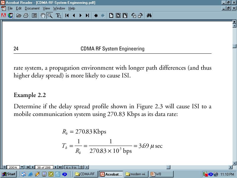
37 Example (Power delay profile) 0 db -10 db P r ( ) 4.38 µs 1.37 µs -20 db -30 db (µs) _ (1)(5) + (0.1)(1) + (0.1)(2) + (0.01)(0) τ = = 4. 38µ s [ ] τ _ (1)(5) + (0.1)(1) + (0.1)(2) + (0.01)(0) = = 21.07µs2 [ ] σ τ = (4.38) = 1. 37µ s 2 2 2
38 Inter Symbol Interference Symbol time 0 db P r ( ) 4.38 µs 1.37 µs -10 db -20 db (µs) db (µs) Symbol time > 10* --- No equalization required Symbol time < 10* --- Equalization will be required to deal with ISI In the above example, symbol time should be more than 14µs to avoid ISI. This means that link speed must be less than 70Kbps (approx)

39 By: Dr.Mohab Mangoud
40
41 2. Coherence Bandwidth While the delay spread is a natural phenomenon caused by multipaths in the radio channel, the coherence bandwidth, B, is a defined relation derived from the rms delay spread. Coherence bandwidth is a statistical measure of the range of frequencies over which the channel can be considered flat (i.e., a channel which passes all spectral components with approximately equal gain and linear phase). Two sinusoids with frequency separation greater than B are affected quite differently by the channel.
42 If the coherence bandwidth is defined as the bandwidth over which the frequency correlation function is above 0.9, then the coherence bandwidth is approximately
43 Time domain view Coherence Bandwidth Freq. domain view x(t) X ( f ) delay spread Range of freq over which response is flat B c High correlation of amplitude between two different freq. components
44 RMS delay spread and coherence BW RMS delay spread and coherence b/w (B c ) are inversely proportional B c α 1 σ τ The image cannot be displayed. Your computer may not have enough memory to open the image, or the image may have been corrupted. Restart your computer, and then open the file again. If the red x still appears, you may have to delete the image and then insert it again. Bc 1 50.σ τ For 0.9 correlation Bc 1 5.σ τ For 0.5 correlation
45 Coherence Bandwidth Example: For a multipath channel, s is given as 1.37ms. The 50% coherence bandwidth is given as: 1/5s = 146kHz. This means that, for a good transmission from a transmitter to a receiver, the range of transmission frequency (channel bandwidth) should not exceed 146kHz, so that all frequencies in this band experience the same channel characteristics. Equalizers are needed in order to use transmission frequencies that are separated larger than this value. This coherence bandwidth is enough for an AMPS channel (30kHz band needed for a channel), but is not enough for a GSM channel (200kHz needed per channel).
46 Revisit Example (Power delay profile) P r ( ) 4.38 µs 1.37 µs 0 db -10 db _ τ = 4. 38µ s -20 db -30 db (µs) σ τ = 1. 37µ s τ _ 2 = 21.07µ s2 1 ( 50% coherence) Bc = 146kHz 5. σ τ Signal bandwidth for Analog Cellular = 30 KHz Signal bandwidth for GSM = 200 KHz
47
48 Doppler spread and coherence time Delay spread and Coherence bandwidth describe the time dispersive nature of the channel in a local area. They don t offer information about the time varying nature of the channel caused by relative motion of transmitter and receiver or the movement of objects in the channel. Doppler Spread and Coherence time are parameters which describe the time varying nature of the channel in a small-scale region.
49 Doppler spread and coherence time Coherence time definition implies that two signals arriving with a time separation greater than T C are affected differently by the channel. Doppler spread and coherence time (T c ) are inversely proportional The image cannot be 1displayed. Your computer may not have enough memory to open the image, or the image may have been corrupted. Restart your computer, and then open the file again. If the red x still appears, you may have to delete the image and then insert it again. Tcα f f m is the max doppler shift m T c 9 16πf m For 0.5 correlation T c f m Rule of thumb
50 Doppler Spread Measure of spectral broadening caused by motion We know how to compute Doppler shift: f d Doppler spread: B D, is defined as the maximum Doppler shift: f m = v/l If the baseband signal bandwidth (B s ) is much greater than (B D ) then effect of Doppler spread is negligible at the receiver.
51 Doppler Shift v Doppler shift Δf = v cosθ λ Example - Carrier frequency f c = 1850 MHz (i.e. = 16.2 cm) - Vehicle speed v = 60 mph = m/s - If the vehicle is moving directly towards the transmitter Δf = = 165Hz If the vehicle is moving perpendicular to the angle of arrival of the transmitted signal Δf = 0
52
53 Types of Small-Scale Fading The type of fading experienced by a signal propagating through a mobile radio channel depends on: the nature of the transmitted signal with respect to the characteristics of the channel.
54
55 Types of Small-scale Fading Small-scale Fading (Based on Multipath Tİme Delay Spread) Flat Fading 1. BW Signal < BW of Channel 2. Delay Spread < Symbol Period Frequency Selective Fading 1. BW Signal > Bw of Channel 2. Delay Spread > Symbol Period Small-scale Fading (Based on Doppler Spread) Fast Fading 1. High Doppler Spread 2. Coherence Time < Symbol Period 3. Channel variations faster than baseband signal variations Slow Fading 1. Low Doppler Spread 2. Coherence Time > Symbol Period 3. Channel variations smaller than baseband signal variations
56 Small scale fading Multipath time delay Flat fading Frequency selective fading B S B C B S B C fading Doppler spread Fast fading Slow fading T S T C T S T C
57
58 Flat Fading Occurs when the amplitude of the received signal changes with time For example according to Rayleigh Distribution Occurs when symbol period of the transmitted signal is much larger than the Delay Spread of the channel Bandwidth of the applied signal is narrow. May cause deep fades. Increase the transmit power to combat this situation.
59 Flat Fading s(t) h(t,t) r(t) t << T S 0 T S 0 t 0 T S +t Occurs when: B S << B C and T S >> s t B C : Coherence bandwidth B S : Signal bandwidth T S : Symbol period s t : Delay Spread
60 Flat Fading
61 Frequency Selective Fading Occurs when channel multipath delay spread is greater than the symbol period. Symbols face time dispersion Channel induces Intersymbol Interference (ISI) Bandwidth of the signal s(t) is wider than the channel impulse response.
62 Frequency Selective Fading s(t) h(t,t) r(t) t >> T S 0 T S 0 t 0 T S +t T S Causes distortion of the received baseband signal Causes Inter-Symbol Interference (ISI) Occurs when: B S > B C and T S < s t As a rule of thumb: T S < s t
63 Frequency Selective Fading
64 Fast Fading Due to Doppler Spread Rate of change of the channel characteristics is larger than the Rate of change of the transmitted signal The channel changes during a symbol period. The channel changes because of receiver motion. Coherence time of the channel is smaller than the symbol period of the transmitter signal Occurs when: B S < B D and T S > T C B S : Bandwidth of the signal B D : Doppler Spread T S : Symbol Period T C : Coherence Bandwidth
65 Slow Fading Due to Doppler Spread Rate of change of the channel characteristics is much smaller than the Rate of change of the transmitted signal Occurs when: B S >> B D and T S << T C B S : Bandwidth of the signal B D : Doppler Spread T S : Symbol Period T C : Coherence Bandwidth
66
67 Fading Distributions Describes how the received signal amplitude changes with time. Remember that the received signal is combination of multiple signals arriving from different directions, phases and amplitudes. With the received signal we mean the baseband signal, namely the envelope of the received signal (i.e. r(t)). Its is a statistical characterization of the multipath fading. Two distributions Rayleigh Fading Ricean Fading
68 Rayleigh and Ricean Distributions Describes the received signal envelope distribution for channels, where all the components are non-los: i.e. there is no line-of sight (LOS) component. Describes the received signal envelope distribution for channels where one of the multipath components is LOS component. i.e. there is one LOS component.
69 Rayleigh Rayleigh distribution has the probability density function (PDF) given by: p( r) = r 2 σ 0 e 2 r 2σ 2 ( 0 ( r < r ) 0) s 2 is the time average power of the received signal before envelope detection. s is the rms value of the received voltage signal before envelope detection Remember: 2 P (average power) V rms (see end of slides 5)
70 Rayleigh The probability that the envelope of the received signal does not exceed a specified value of R is given by the CDF: r r r P mean median rms R R = = σ ( R) Pr ( r R) p( r) dr = 1 e 0 = = E[ r] = = 1.177σ 2σ 0 rp( r) dr = σ foundby solving π = σ = r median 0 p( r) dr
71 Rayleigh PDF /s mean = s median = 1.177s variance = s s 2s 3s 4s 5s
72 Ricean Distribution When there is a stationary (non-fading) LOS signal present, then the envelope distribution is Ricean. The Ricean distribution degenerates to Rayleigh when the dominant component fades away.
73 How do systems handle fading problem? Analog Narrowband transmission GSM Adaptive channel equalization Channel estimation training sequence DECT Use the handset only in small cells with small delay spreads Diversity and channel selection can help a little bit (pick a channel where late reflections are in a fade) IS95 Cellular CDMA Rake receiver separately recovers signals over paths with excessive delays Digital Audio Broacasting OFDM multi-carrier modulation: The radio channel is split into many narrowband (ISI- free) subchannels
74
75
76
Wireless Channel Propagation Model Small-scale Fading
 Wireless Channel Propagation Model Small-scale Fading Basic Questions T x What will happen if the transmitter - changes transmit power? - changes frequency? - operates at higher speed? Transmit power,
ECE 476/ECE 501C/CS Wireless Communication Systems Winter Lecture 6: Fading
 ECE 476/ECE 501C/CS 513 - Wireless Communication Systems Winter 2004 Lecture 6: Fading Last lecture: Large scale propagation properties of wireless systems - slowly varying properties that depend primarily
ECE 476/ECE 501C/CS Wireless Communication Systems Winter Lecture 6: Fading
 ECE 476/ECE 501C/CS 513 - Wireless Communication Systems Winter 2005 Lecture 6: Fading Last lecture: Large scale propagation properties of wireless systems - slowly varying properties that depend primarily
ECE 476/ECE 501C/CS Wireless Communication Systems Winter Lecture 6: Fading
 ECE 476/ECE 501C/CS 513 - Wireless Communication Systems Winter 2003 Lecture 6: Fading Last lecture: Large scale propagation properties of wireless systems - slowly varying properties that depend primarily
Mobile Radio Propagation: Small-Scale Fading and Multi-path
 Mobile Radio Propagation: Small-Scale Fading and Multi-path 1 EE/TE 4365, UT Dallas 2 Small-scale Fading Small-scale fading, or simply fading describes the rapid fluctuation of the amplitude of a radio
Mobile Radio Propagation Channel Models
 Wireless Information Transmission System Lab. Mobile Radio Propagation Channel Models Institute of Communications Engineering National Sun Yat-sen University Table of Contents Introduction Propagation
Chapter 5 Small-Scale Fading and Multipath. School of Information Science and Engineering, SDU
 Chapter 5 Small-Scale Fading and Multipath School of Information Science and Engineering, SDU Outline Small-Scale Multipath Propagation Impulse Response Model of a Multipath Channel Small-Scale Multipath
Channel. Muhammad Ali Jinnah University, Islamabad Campus, Pakistan. Multi-Path Fading. Dr. Noor M Khan EE, MAJU
 Instructor: Prof. Dr. Noor M. Khan Department of Electronic Engineering, Muhammad Ali Jinnah University, Islamabad Campus, Islamabad, PAKISTAN Ph: +9 (51) 111-878787, Ext. 19 (Office), 186 (Lab) Fax: +9
Multi-Path Fading Channel
 Instructor: Prof. Dr. Noor M. Khan Department of Electronic Engineering, Muhammad Ali Jinnah University, Islamabad Campus, Islamabad, PAKISTAN Ph: +9 (51) 111-878787, Ext. 19 (Office), 186 (Lab) Fax: +9
Muhammad Ali Jinnah University, Islamabad Campus, Pakistan. Fading Channel. Base Station
 Fading Lecturer: Assoc. Prof. Dr. Noor M Khan Department of Electronic Engineering, Muhammad Ali Jinnah University, Islamabad Campus, Islamabad, PAKISTAN Ph: +9 (51) 111-878787, Ext. 19 (Office), 186 (ARWiC
Small-Scale Fading I PROF. MICHAEL TSAI 2011/10/27
 Small-Scale Fading I PROF. MICHAEL TSAI 011/10/7 Multipath Propagation RX just sums up all Multi Path Component (MPC). Multipath Channel Impulse Response An example of the time-varying discrete-time impulse
Digital Communications over Fading Channel s
 over Fading Channel s Instructor: Prof. Dr. Noor M Khan Department of Electronic Engineering, Muhammad Ali Jinnah University, Islamabad Campus, Islamabad, PAKISTAN Ph: +9 (51) 111-878787, Ext. 19 (Office),
WIRELESS COMMUNICATION TECHNOLOGIES (16:332:546) LECTURE 5 SMALL SCALE FADING
 LECTURE 5 SMALL SCALE FADING") WIRELESS COMMUNICATION TECHNOLOGIES (16:332:546) LECTURE 5 SMALL SCALE FADING Instructor: Dr. Narayan Mandayam Slides: SabarishVivek Sarathy A QUICK RECAP Why is there poor signal reception in urban clutters?
WIRELESS COMMUNICATION TECHNOLOGIES (16:332:546) LECTURE 5 SMALL SCALE FADING Instructor: Dr. Narayan Mandayam Slides: SabarishVivek Sarathy A QUICK RECAP Why is there poor signal reception in urban clutters?
Text Book. References. Andrea Goldsmith, Wireless Communications, Cambridge University Press Wireless Communications
 Ammar Abu-Hudrouss Islamic University Gaza ١ Course Syllabus Text Boo Andrea Goldsmith,, Cambridge University Press 005. References 1. Rappaport, : Principles and Practice, Prentice Hall nd Ed. D. N. C.
The Radio Channel. COS 463: Wireless Networks Lecture 14 Kyle Jamieson. [Parts adapted from I. Darwazeh, A. Goldsmith, T. Rappaport, P.
 The Radio Channel COS 463: Wireless Networks Lecture 14 Kyle Jamieson [Parts adapted from I. Darwazeh, A. Goldsmith, T. Rappaport, P. Steenkiste] Motivation The radio channel is what limits most radio
CHAPTER 2 WIRELESS CHANNEL
 CHAPTER 2 WIRELESS CHANNEL 2.1 INTRODUCTION In mobile radio channel there is certain fundamental limitation on the performance of wireless communication system. There are many obstructions between transmitter
NETW 701: Wireless Communications. Lecture 5. Small Scale Fading
 NETW 701: Wireless Communications Lecture 5 Small Scale Fading Small Scale Fading Most mobile communication systems are used in and around center of population. The transmitting antenna or Base Station
Mobile Radio Propagation Channel Models
 Wireless Information Transmission System Lab. Mobile Radio Propagation Channel Models Institute of Communications Engineering National Sun Yat-sen University Table of Contents Introduction Propagation
EC 551 Telecommunication System Engineering. Mohamed Khedr
 EC 551 Telecommunication System Engineering Mohamed Khedr http://webmail.aast.edu/~khedr 1 Mohamed Khedr., 2008 Syllabus Tentatively Week 1 Week 2 Week 3 Week 4 Week 5 Week 6 Week 7 Week 8 Week 9 Week
Written Exam Channel Modeling for Wireless Communications - ETIN10
 Written Exam Channel Modeling for Wireless Communications - ETIN10 Department of Electrical and Information Technology Lund University 2017-03-13 2.00 PM - 7.00 PM A minimum of 30 out of 60 points are
Unit 7 - Week 6 - Wide Sense Stationary Uncorrelated Scattering (WSSUS) Channel Model
 Channel Model") X Courses» Introduction to Wireless and Cellular Communications Announcements Course Forum Progress Mentor Unit 7 - Week 6 - Wide Sense Stationary Uncorrelated Scattering (WSSUS) Channel Model Course outline
X Courses» Introduction to Wireless and Cellular Communications Announcements Course Forum Progress Mentor Unit 7 - Week 6 - Wide Sense Stationary Uncorrelated Scattering (WSSUS) Channel Model Course outline
Wireless Communication: Concepts, Techniques, and Models. Hongwei Zhang
 Wireless Communication: Concepts, Techniques, and Models Hongwei Zhang http://www.cs.wayne.edu/~hzhang Outline Digital communication over radio channels Channel capacity MIMO: diversity and parallel channels
EC 551 Telecommunication System Engineering. Mohamed Khedr
 EC 551 Telecommunication System Engineering Mohamed Khedr http://webmail.aast.edu/~khedr 1 Mohamed Khedr., 2008 Syllabus Tentatively Week 1 Week 2 Week 3 Week 4 Week 5 Week 6 Week 7 Week 8 Week 9 Week
Application Note 37. Emulating RF Channel Characteristics
 Application Note 37 Emulating RF Channel Characteristics Wireless communication is one of the most demanding applications for the telecommunications equipment designer. Typical signals at the receiver
WIRELESS COMMUNICATIONS PRELIMINARIES
 WIRELESS COMMUNICATIONS Preliminaries Radio Environment Modulation Performance PRELIMINARIES db s and dbm s Frequency/Time Relationship Bandwidth, Symbol Rate, and Bit Rate 1 DECIBELS Relative signal strengths
9.4 Temporal Channel Models
 ECEn 665: Antennas and Propagation for Wireless Communications 127 9.4 Temporal Channel Models The Rayleigh and Ricean fading models provide a statistical model for the variation of the power received
Chapter 3. Mobile Radio Propagation
 Chapter 3 Mobile Radio Propagation Based on the slides of Dr. Dharma P. Agrawal, University of Cincinnati and Dr. Andrea Goldsmith, Stanford University Propagation Mechanisms Outline Radio Propagation
Mobile Communications
 Mobile Communications Wen-Shen Wuen Trans. Wireless Technology Laboratory National Chiao Tung University WS Wuen Mobile Communications 1 Outline Outline 1 Small-Scale Multipath Propagation 2 Impulse Response
Fundamentals of Wireless Communication
 Fundamentals of Wireless Communication David Tse University of California, Berkeley Pramod Viswanath University of Illinois, Urbana-Champaign Fundamentals of Wireless Communication, Tse&Viswanath 1. Introduction
Wideband Channel Characterization. Spring 2017 ELE 492 FUNDAMENTALS OF WIRELESS COMMUNICATIONS 1
 Wideband Channel Characterization Spring 2017 ELE 492 FUNDAMENTALS OF WIRELESS COMMUNICATIONS 1 Wideband Systems - ISI Previous chapter considered CW (carrier-only) or narrow-band signals which do NOT
Narrow- and wideband channels
 RADIO SYSTEMS ETIN15 Lecture no: 3 Narrow- and wideband channels Ove Edfors, Department of Electrical and Information technology Ove.Edfors@eit.lth.se 2012-03-19 Ove Edfors - ETIN15 1 Contents Short review
MSIT 413: Wireless Technologies Week 3
 MSIT 413: Wireless Technologies Week 3 Michael L. Honig Department of EECS Northwestern University January 2016 Why Study Radio Propagation? To determine coverage Can we use the same channels? Must determine
Chapter 2 Channel Equalization
 Chapter 2 Channel Equalization 2.1 Introduction In wireless communication systems signal experiences distortion due to fading [17]. As signal propagates, it follows multiple paths between transmitter and
CALIFORNIA STATE UNIVERSITY, NORTHRIDGE FADING CHANNEL CHARACTERIZATION AND MODELING
 CALIFORNIA STATE UNIVERSITY, NORTHRIDGE FADING CHANNEL CHARACTERIZATION AND MODELING A graduate project submitted in partial fulfillment of the requirements For the degree of Master of Science in Electrical
Testing c2k Mobile Stations Using a Digitally Generated Faded Signal
 Testing c2k Mobile Stations Using a Digitally Generated Faded Signal Agenda Overview of Presentation Fading Overview Mitigation Test Methods Agenda Fading Presentation Fading Overview Mitigation Test Methods
Advanced Communication Systems -Wireless Communication Technology
 Advanced Communication Systems -Wireless Communication Technology Dr. Junwei Lu The School of Microelectronic Engineering Faculty of Engineering and Information Technology Outline Introduction to Wireless
Narrow- and wideband channels
 RADIO SYSTEMS ETIN15 Lecture no: 3 Narrow- and wideband channels Ove Edfors, Department of Electrical and Information technology Ove.Edfors@eit.lth.se 27 March 2017 1 Contents Short review NARROW-BAND
SIMULATION MODELING OF STATISTICAL NAKAGAMI-m FADING CHANNELS MASTER OF ENGINEERING (M.E.) ELECTRONICS AND COMMUNICATION ENGINEERING MANNAM RAMA RAO
 ELECTRONICS AND COMMUNICATION ENGINEERING MANNAM RAMA RAO") SIMULATION MODELING OF STATISTICAL NAKAGAMI-m FADING CHANNELS Thesis submitted in partial fulfillment of the requirement for the award of the degree of MASTER OF ENGINEERING (M.E.) In ELECTRONICS AND COMMUNICATION
SIMULATION MODELING OF STATISTICAL NAKAGAMI-m FADING CHANNELS Thesis submitted in partial fulfillment of the requirement for the award of the degree of MASTER OF ENGINEERING (M.E.) In ELECTRONICS AND COMMUNICATION
1.1 Introduction to the book
 1 Introduction 1.1 Introduction to the book Recent advances in wireless communication systems have increased the throughput over wireless channels and networks. At the same time, the reliability of wireless
MSIT 413: Wireless Technologies Week 3
 MSIT 413: Wireless Technologies Week 3 Michael L. Honig Department of EECS Northwestern University October 2017 Why Study Radio Propagation? To determine coverage Can we use the same channels? Must determine
RECOMMENDATION ITU-R P The prediction of the time and the spatial profile for broadband land mobile services using UHF and SHF bands
 Rec. ITU-R P.1816 1 RECOMMENDATION ITU-R P.1816 The prediction of the time and the spatial profile for broadband land mobile services using UHF and SHF bands (Question ITU-R 211/3) (2007) Scope The purpose
Lecture 1 Wireless Channel Models
 MIMO Communication Systems Lecture 1 Wireless Channel Models Prof. Chun-Hung Liu Dept. of Electrical and Computer Engineering National Chiao Tung University Spring 2017 2017/3/2 Lecture 1: Wireless Channel
UWB Channel Modeling
 Channel Modeling ETIN10 Lecture no: 9 UWB Channel Modeling Fredrik Tufvesson & Johan Kåredal, Department of Electrical and Information Technology fredrik.tufvesson@eit.lth.se 2011-02-21 Fredrik Tufvesson
Part 4. Communications over Wireless Channels
 Part 4. Communications over Wireless Channels p. 1 Wireless Channels Performance of a wireless communication system is basically limited by the wireless channel wired channel: stationary and predicable
Channel Modeling ETI 085
 Channel Modeling ETI 085 Overview Lecture no: 9 What is Ultra-Wideband (UWB)? Why do we need UWB channel models? UWB Channel Modeling UWB channel modeling Standardized UWB channel models Fredrik Tufvesson
Antennas and Propagation
 Antennas and Propagation Chapter 5 Introduction An antenna is an electrical conductor or system of conductors Transmission - radiates electromagnetic energy into space Reception - collects electromagnetic
Welcome to the next lecture on mobile radio propagation. (Refer Slide Time: 00:01:23 min)
") Wireless Communications Dr. Ranjan Bose Department of Electrical Engineering Indian Institute of Technology, Delhi Lecture No # 20 Mobile Radio Propagation -11- Multipath and Small Scale Fading Welcome
Wireless Communications Dr. Ranjan Bose Department of Electrical Engineering Indian Institute of Technology, Delhi Lecture No # 20 Mobile Radio Propagation -11- Multipath and Small Scale Fading Welcome
Revision of Lecture One
 Revision of Lecture One System blocks and basic concepts Multiple access, MIMO, space-time Transceiver Wireless Channel Signal/System: Bandpass (Passband) Baseband Baseband complex envelope Linear system:
Antennas & Propagation. CSG 250 Fall 2007 Rajmohan Rajaraman
 Antennas & Propagation CSG 250 Fall 2007 Rajmohan Rajaraman Introduction An antenna is an electrical conductor or system of conductors o Transmission - radiates electromagnetic energy into space o Reception
Project = An Adventure : Wireless Networks. Lecture 4: More Physical Layer. What is an Antenna? Outline. Page 1
 Project = An Adventure 18-759: Wireless Networks Checkpoint 2 Checkpoint 1 Lecture 4: More Physical Layer You are here Done! Peter Steenkiste Departments of Computer Science and Electrical and Computer
Channel Models. Spring 2017 ELE 492 FUNDAMENTALS OF WIRELESS COMMUNICATIONS 1
 Channel Models Spring 2017 ELE 492 FUNDAMENTALS OF WIRELESS COMMUNICATIONS 1 Narrowband Channel Models Statistical Approach: Impulse response modeling: A narrowband channel can be represented by an impulse
Wireless Physical Layer Concepts: Part II
 Wireless Physical Layer Concepts: Part II Raj Jain Professor of CSE Washington University in Saint Louis Saint Louis, MO 63130 Jain@cse.wustl.edu Audio/Video recordings of this lecture are available at:
Performance Evaluation Of Digital Modulation Techniques In Awgn Communication Channel
 Performance Evaluation Of Digital Modulation Techniques In Awgn Communication Channel Oyetunji S. A 1 and Akinninranye A. A 2 1 Federal University of Technology Akure, Nigeria 2 MTN Nigeria Abstract The
UNIK4230: Mobile Communications Spring 2013
 UNIK4230: Mobile Communications Spring 2013 Abul Kaosher abul.kaosher@nsn.com Mobile: 99 27 10 19 1 UNIK4230: Mobile Communications Propagation characteristis of wireless channel Date: 07.02.2013 2 UNIK4230:
Microwave Seminar. Noise and Bit Error Ratio. J. Richie. Spring 2013
 Microwave Seminar Noise and Bit Error Ratio J. Richie Spring 2013 Outline Noise Noise and Equivalent Temperature Noise Figure Small Scale Fade and Multipath Impulse Response Model Types of Fading Modulation
MSIT 413: Wireless Technologies Week 4
 MSIT 413: Wireless Technologies Week 4 Michael L. Honig Department of EECS Northwestern University February 2014 1 Outline Finish radio propagation Applications: location tracking (radar), handoffs Digital
TEMPUS PROJECT JEP Wideband Analysis of the Propagation Channel in Mobile Broadband System
 Department of Electrical Engineering and Computer Science TEMPUS PROJECT JEP 743-94 Wideband Analysis of the Propagation Channel in Mobile Broadband System Krzysztof Jacek Kurek Final report Supervisor:
Ultra Wideband Radio Propagation Measurement, Characterization and Modeling
 Ultra Wideband Radio Propagation Measurement, Characterization and Modeling Rachid Saadane rachid.saadane@gmail.com GSCM LRIT April 14, 2007 achid Saadane rachid.saadane@gmail.com ( GSCM Ultra Wideband
Antennas and Propagation. Chapter 5
 Antennas and Propagation Chapter 5 Introduction An antenna is an electrical conductor or system of conductors Transmission - radiates electromagnetic energy into space Reception - collects electromagnetic
Effects of Fading Channels on OFDM
 IOSR Journal of Engineering (IOSRJEN) e-issn: 2250-3021, p-issn: 2278-8719, Volume 2, Issue 9 (September 2012), PP 116-121 Effects of Fading Channels on OFDM Ahmed Alshammari, Saleh Albdran, and Dr. Mohammad
EITN85, FREDRIK TUFVESSON, JOHAN KÅREDAL ELECTRICAL AND INFORMATION TECHNOLOGY. Why do we need UWB channel models?
 Wireless Communication Channels Lecture 9:UWB Channel Modeling EITN85, FREDRIK TUFVESSON, JOHAN KÅREDAL ELECTRICAL AND INFORMATION TECHNOLOGY Overview What is Ultra-Wideband (UWB)? Why do we need UWB channel
CHAPTER 6 THE WIRELESS CHANNEL
 CHAPTER 6 THE WIRELESS CHANNEL These slides are made available to faculty in PowerPoint form. Slides can be freely added, modified, and deleted to suit student needs. They represent substantial work on
Revision of Lecture One
 Revision of Lecture One System block Transceiver Wireless Channel Signal / System: Bandpass (Passband) Baseband Baseband complex envelope Linear system: complex (baseband) channel impulse response Channel:
Statistical multipath channel models
 Statistical multipath channel models 1. ABSTRACT *) in this seminar we examine fading models for the constructive and destructive addition of different multipath component *) science deterministic channel
ANALOGUE TRANSMISSION OVER FADING CHANNELS
 J.P. Linnartz EECS 290i handouts Spring 1993 ANALOGUE TRANSMISSION OVER FADING CHANNELS Amplitude modulation Various methods exist to transmit a baseband message m(t) using an RF carrier signal c(t) =
Diversity. Spring 2017 ELE 492 FUNDAMENTALS OF WIRELESS COMMUNICATIONS 1
 Diversity Spring 2017 ELE 492 FUNDAMENTALS OF WIRELESS COMMUNICATIONS 1 Diversity A fading channel with an average SNR has worse BER performance as compared to that of an AWGN channel with the same SNR!.
Characterization of a Very Shallow Water Acoustic Communication Channel MTS/IEEE OCEANS 09 Biloxi, MS
 Characterization of a Very Shallow Water Acoustic Communication Channel MTS/IEEE OCEANS 09 Biloxi, MS Brian Borowski Stevens Institute of Technology Departments of Computer Science and Electrical and Computer
Antennas and Propagation
 Mobile Networks Module D-1 Antennas and Propagation 1. Introduction 2. Propagation modes 3. Line-of-sight transmission 4. Fading Slides adapted from Stallings, Wireless Communications & Networks, Second
Orthogonal Frequency Division Multiplexing (OFDM) based Uplink Multiple Access Method over AWGN and Fading Channels
 based Uplink Multiple Access Method over AWGN and Fading Channels") Orthogonal Frequency Division Multiplexing (OFDM) based Uplink Multiple Access Method over AWGN and Fading Channels Prashanth G S 1 1Department of ECE, JNNCE, Shivamogga ---------------------------------------------------------------------***----------------------------------------------------------------------
Orthogonal Frequency Division Multiplexing (OFDM) based Uplink Multiple Access Method over AWGN and Fading Channels Prashanth G S 1 1Department of ECE, JNNCE, Shivamogga ---------------------------------------------------------------------***----------------------------------------------------------------------
SNS COLLEGE OF ENGINEERING COIMBATORE DEPARTMENT OF INFORMATION TECHNOLOGY QUESTION BANK
 SNS COLLEGE OF ENGINEERING COIMBATORE 641107 DEPARTMENT OF INFORMATION TECHNOLOGY QUESTION BANK EC6801 WIRELESS COMMUNICATION UNIT-I WIRELESS CHANNELS PART-A 1. What is propagation model? 2. What are the
Implementation of a MIMO Transceiver Using GNU Radio
 ECE 4901 Fall 2015 Implementation of a MIMO Transceiver Using GNU Radio Ethan Aebli (EE) Michael Williams (EE) Erica Wisniewski (CMPE/EE) The MITRE Corporation 202 Burlington Rd Bedford, MA 01730 Department
Lecture 13. Introduction to OFDM
 Lecture 13 Introduction to OFDM Ref: About-OFDM.pdf Orthogonal frequency division multiplexing (OFDM) is well-known to be effective against multipath distortion. It is a multicarrier communication scheme,
Channel Modelling for Beamforming in Cellular Systems
 Channel Modelling for Beamforming in Cellular Systems Salman Durrani Department of Engineering, The Australian National University, Canberra. Email: salman.durrani@anu.edu.au DERF June 26 Outline Introduction
Wireless Communication Fundamentals Feb. 8, 2005
 Wireless Communication Fundamentals Feb. 8, 005 Dr. Chengzhi Li 1 Suggested Reading Chapter Wireless Communications by T. S. Rappaport, 001 (version ) Rayleigh Fading Channels in Mobile Digital Communication
Analysis of Fast Fading in Wireless Communication Channels M.Siva Ganga Prasad 1, P.Siddaiah 1, L.Pratap Reddy 2, K.Lekha 1
 International Journal of ISSN 0974-2107 Systems and Technologies IJST Vol.3, No.1, pp 139-145 KLEF 2010 Fading in Wireless Communication Channels M.Siva Ganga Prasad 1, P.Siddaiah 1, L.Pratap Reddy 2,
Exam 3 is two weeks from today. Today s is the final lecture that will be included on the exam.
 ECE 5325/6325: Wireless Communication Systems Lecture Notes, Spring 2010 Lecture 19 Today: (1) Diversity Exam 3 is two weeks from today. Today s is the final lecture that will be included on the exam.
King Fahd University of Petroleum & Minerals Computer Engineering Dept
 King Fahd University of Petroleum & Minerals Computer Engineering Dept COE 543 Mobile and Wireless Networks Term 0 Dr. Ashraf S. Hasan Mahmoud Rm -148-3 Ext. 174 Email: ashraf@ccse.kfupm.edu.sa 4//003
Outline / Wireless Networks and Applications Lecture 5: Physical Layer Signal Propagation and Modulation
 Outline 18-452/18-750 Wireless Networks and Applications Lecture 5: Physical Layer Signal Propagation and Modulation Peter Steenkiste Carnegie Mellon University Spring Semester 2017 http://www.cs.cmu.edu/~prs/wirelesss17/
Session2 Antennas and Propagation
 Wireless Communication Presented by Dr. Mahmoud Daneshvar Session2 Antennas and Propagation 1. Introduction Types of Anttenas Free space Propagation 2. Propagation modes 3. Transmission Problems 4. Fading
Lecture 7/8: UWB Channel. Kommunikations
 Lecture 7/8: UWB Channel Kommunikations Technik UWB Propagation Channel Radio Propagation Channel Model is important for Link level simulation (bit error ratios, block error ratios) Coverage evaluation
ECS455: Chapter 5 OFDM
 ECS455: Chapter 5 OFDM 1 Dr.Prapun Suksompong www.prapun.com Office Hours: Library (Rangsit) Mon 16:20-16:50 BKD 3601-7 Wed 9:20-11:20 OFDM Applications 802.11 Wi-Fi: a/g/n/ac versions DVB-T (Digital Video
Multipath fading effects on short range indoor RF links. White paper
 ALCIOM 5, Parvis Robert Schuman 92370 CHAVILLE - FRANCE Tel/Fax : 01 47 09 30 51 contact@alciom.com www.alciom.com Project : Multipath fading effects on short range indoor RF links DOCUMENT : REFERENCE
Mobile and Personal Communications. Dr Mike Fitton, Telecommunications Research Lab Toshiba Research Europe Limited
 Mobile and Personal Communications Dr Mike Fitton, mike.fitton@toshiba-trel.com Telecommunications Research Lab Toshiba Research Europe Limited 1 Mobile and Personal Communications Outline of Lectures
Antennas and Propagation. Chapter 5
 Antennas and Propagation Chapter 5 Introduction An antenna is an electrical conductor or system of conductors Transmission - radiates electromagnetic energy into space Reception - collects electromagnetic
Receiver Designs for the Radio Channel
 Receiver Designs for the Radio Channel COS 463: Wireless Networks Lecture 15 Kyle Jamieson [Parts adapted from C. Sodini, W. Ozan, J. Tan] Today 1. Delay Spread and Frequency-Selective Fading 2. Time-Domain
Performance of Orthogonal Frequency Division Multiplexing System Based on Mobile Velocity and Subcarrier
 Journal of Computer Science 6 (): 94-98, 00 ISSN 549-3636 00 Science Publications Performance of Orthogonal Frequency Division Multiplexing System ased on Mobile Velocity and Subcarrier Zulkeflee in halidin
5 GHz Radio Channel Modeling for WLANs
 5 GHz Radio Channel Modeling for WLANs S-72.333 Postgraduate Course in Radio Communications Jarkko Unkeri jarkko.unkeri@hut.fi 54029P 1 Outline Introduction IEEE 802.11a OFDM PHY Large-scale propagation
ECE6604 PERSONAL & MOBILE COMMUNICATIONS. Week 2. Interference and Shadow Margins, Handoff Gain, Coverage Capacity, Flat Fading
 ECE6604 PERSONAL & MOBILE COMMUNICATIONS Week 2 Interference and Shadow Margins, Handoff Gain, Coverage Capacity, Flat Fading 1 Interference Margin As the subscriber load increases, additional interference
Performance Study of OFDM Over Fading Channels for Wireless Communications
 University of Denver Digital Commons @ DU Electronic Theses and Dissertations Graduate Studies 1-1-2012 Performance Study of OFDM Over Fading Channels for Wireless Communications Ahmed Alshammari University
OFDM system: Discrete model Spectral efficiency Characteristics. OFDM based multiple access schemes. OFDM sensitivity to synchronization errors
 Introduction - Motivation OFDM system: Discrete model Spectral efficiency Characteristics OFDM based multiple access schemes OFDM sensitivity to synchronization errors 4 OFDM system Main idea: to divide
Unit 5 - Week 4 - Multipath Fading Environment
 2/29/207 Introduction to ireless and Cellular Communications - - Unit 5 - eek 4 - Multipath Fading Environment X Courses Unit 5 - eek 4 - Multipath Fading Environment Course outline How to access the portal
SC - Single carrier systems One carrier carries data stream
 Digital modulation SC - Single carrier systems One carrier carries data stream MC - Multi-carrier systems Many carriers are used for data transmission. Data stream is divided into sub-streams and each
ROOT MULTIPLE SIGNAL CLASSIFICATION SUPER RESOLUTION TECHNIQUE FOR INDOOR WLAN CHANNEL CHARACTERIZATION. Dr. Galal Nadim
 ROOT MULTIPLE SIGNAL CLASSIFICATION SUPER RESOLUTION TECHNIQUE FOR INDOOR WLAN CHANNEL CHARACTERIZATION Dr. Galal Nadim BRIEF DESCRIPTION The root-multiple SIgnal Classification (root- MUSIC) super resolution
Transmit Diversity Schemes for CDMA-2000
 1 of 5 Transmit Diversity Schemes for CDMA-2000 Dinesh Rajan Rice University 6100 Main St. Houston, TX 77005 dinesh@rice.edu Steven D. Gray Nokia Research Center 6000, Connection Dr. Irving, TX 75240 steven.gray@nokia.com
ECE5984 Orthogonal Frequency Division Multiplexing and Related Technologies Fall Mohamed Essam Khedr. Fading Channels
 ECE5984 Orthogonal Frequency Division Multiplexing and Related Technologies Fall 2007 Mohamed Essam Khedr Fading Channels Major Learning Objectives Upon successful completion of the course the student
RRC Vehicular Communications Part II Radio Channel Characterisation
 RRC Vehicular Communications Part II Radio Channel Characterisation Roberto Verdone Slides are provided as supporting tool, they are not a textbook! Outline 1. Fundamentals of Radio Propagation 2. Large
IEEE Working Group on Mobile Broadband Wireless Access <http://grouper.ieee.org/groups/802/mbwa>
 2003-01-10 IEEE C802.20-03/09 Project Title IEEE 802.20 Working Group on Mobile Broadband Wireless Access Channel Modeling Suitable for MBWA Date Submitted Source(s)
Performance Analysis of Different Ultra Wideband Modulation Schemes in the Presence of Multipath
 Application Note AN143 Nov 6, 23 Performance Analysis of Different Ultra Wideband Modulation Schemes in the Presence of Multipath Maurice Schiff, Chief Scientist, Elanix, Inc. Yasaman Bahreini, Consultant
Lecture 3: Wireless Physical Layer: Modulation Techniques. Mythili Vutukuru CS 653 Spring 2014 Jan 13, Monday
 Lecture 3: Wireless Physical Layer: Modulation Techniques Mythili Vutukuru CS 653 Spring 2014 Jan 13, Monday Modulation We saw a simple example of amplitude modulation in the last lecture Modulation how
Lecture 7. Traditional Transmission (Narrowband) Small Scale Fading Time Variation
 Small Scale Fading Time Variation") Lecture 7 Traditional Transmission (Narrowband) Small Scale Fading Time Variation Communication Issues and Radio 2 Propagation Fading Channels Large Scale Fading Small Scale Fading Path-Loss & Shadowing
Lecture 7 Traditional Transmission (Narrowband) Small Scale Fading Time Variation Communication Issues and Radio 2 Propagation Fading Channels Large Scale Fading Small Scale Fading Path-Loss & Shadowing