Mechatronics UNIT I. Introduction of sensors and actuators
|
|
|
- Allan King
- 5 years ago
- Views:
Transcription
1 Mechatronics UNIT I Introduction of sensors and actuators Prepared By Prof. Shinde Vishal Vasant Assistant Professor Dept. of Mechanical Engg. NDMVP S Karmaveer Baburao Thakare College of Engg. Nashik Contact No E mail:- shinde.vishal@kbtcoe.org Website:- 22/02/2017 1
2 Syllabus Introduction to Sensors & Actuators Introduction to Mechatronics, Measurement characteristics: - Static and Dynamic Sensors: Position Sensors: - Potentiometer, LVDT, Encoders; Proximity sensors:- Optical, Inductive, Capacitive; Motion Sensors:- Variable Reluctance; Temperature Sensor: RTD, Thermocouples; Force / Pressure Sensors:- Strain gauges; Flow sensors: - Electromagnetic Actuators: Stepper motor, Servo motor, Solenoids 22/02/2017 2
3 Objectives 1. Understand key elements of Mechatronics system, representation into block diagram 2. Understand concept of transfer function, reduction and analysis 3. Understand principles of sensors, its characteristics, interfacing with DAQ microcontroller 4. Understand the concept of PLC system and its ladder programming, and significance of PLC systems in industrial application 5. Understand the system modeling and analysis in time domain and frequency domain. 6. Understand control actions such as Proportional, derivative and integral and study its significance in industrial applications. 22/02/2017 3
4 Outcomes 1. Identification of key elements of mechatronics system and its representation in terms of block diagram 2. Understanding the concept of signal processing and use of interfacing systems such as ADC, DAC, digital I/O 3. Interfacing of Sensors, Actuators using appropriate DAQ micro-controller 4. Time and Frequency domain analysis of system model (for control application) 5. PID control implementation on real time systems 6. Development of PLC ladder programming and implementation of real life system 22/02/2017 4
5 What is Mechatronics Mechatronics is the synergistic combination of mechanical engineering ( mecha for mechanisms), electronic engineering ( tronics for electronics), and software engineering. The word mechatronics was first coined by Mr. Tetsuro Moria, a senior engineer of a Japanese company, Yaskawa, in /02/2017 5
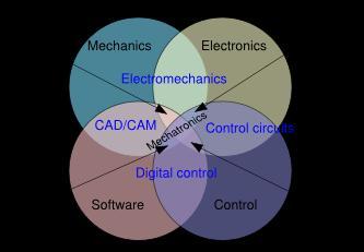
6 22/02/2017 6

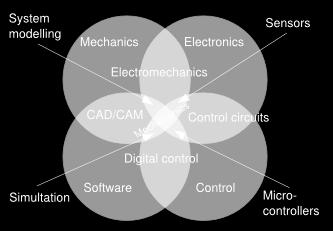
7 Working definition Mechatronics is the synergistic integration of sensors, actuators, signal conditioning, power electronics, decision and control algorithms, and computer hardware and software to manage complexity, uncertainty, and communication in engineered systems. 22/02/2017 Graphical Representation Prof. V. V. Shinde NDMVP'S of Mechatronics KBT COE 7
8 Elements of Mechatronics 22/02/2017 8
9 Basic Measurement System Sensor Processor or Signal Conditioner Display RTD Potentiometer Strain Gage LVDT Wheatstone Bridge Operational Amplifier Digital Analog 22/02/2017 9
10 Characteristics of measurement systems To choose the instrument, most suited to a particular measurement application, we have to know the system characteristics. The performance characteristics may be broadly divided into two groups, namely static and dynamic characteristics. Static characteristics the performance criteria for the measurement of quantities that remain constant, or vary only quite slowly. The static characteristics are defined for the instruments which measure quantities which do not vary with time. Dynamic characteristics the relationship between the system input and output when the measured quantity (measurand) is varying rapidly. 22/02/
11 The main static characteristics are :- 1. Accuracy 2. Sensitivity 3. Reproducibility 4. Drift 5. Static error 6. Dead zone 7. Precision 8. Threshold 9. Linearity 10. Stability 11. Range or Span 12. Bais 13. Tolerance 14. Hysteresis 22/02/
12 Accuracy It is the degree of closeness with which an instrument reading approaches the true value of the quantity being measured. The accuracy of a measurement indicates the nearness to the actual/true value of the quantity. Accuracy is the Difference between the measured value and the true value. 22/02/
13 Precision It is a measure of the reproducibility of the measurement that is given a fixed value of variable. Precision is a measure of the degree to which successive measurements differ from each other. For example consider an instrument on which readings can be taken upto th of unit. The instrument has zero adjustment error. So, when we take a readings, the instrument is highly precise. However as the instrument has a zero adjustment error the readings obtained are precise, but they are not accurate. Thus, when a set of readings show precision, the results agree among themselves. However, it is not essential that the results are accurate. 22/02/

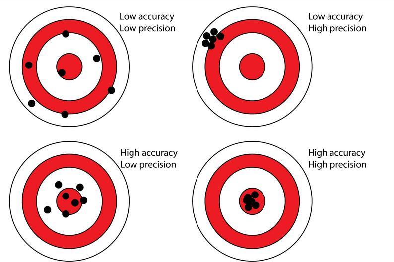
14 Accuracy and Precision 22/02/
15 Reproducibility Reproducibility is defined as the degree of closeness by which a given value can be repeatedly measured. The reproducibility is specified for a period of time. Perfect reproducibility signifies that the given readings that are taken for an input, do not vary with time. Describes the closeness of output readings for the same input when there are changes in the method of measurement, observer, measuring instruments, location etc Repeatability Describes the closeness of output reading when same input is applied repetitively over a short periods of time with the same measurement condition, same instruments and observer, same location and same conditions of use maintained throughout. 22/02/
16 Drift The drift is defined as the gradual shift in the indication over a period of time where in the input variable does not change. Drift is a variation in the instrument output which is not caused by any change of input, it may caused by internal temperature changes and component instability Drift may be caused because of environment factors like stray electric fields, stray magnetic fields, thermal e.m.f s, changes in temperature, mechanical vibrations etc. Drift is classified into three categories: Zero drift Span drift or sensitivity drift Zonal drift 22/02/
17 Sensitivity Sensitivity is the ratio of change in output of an instrument to the change in input. Sensitivity states that smallest change in the value of measured variable to which the instrument/device responds The manufactures specify sensitivity as the ratio of magnitude of the measured quantity to the magnitude of the response. This ratio is called as Inverse sensitivity or deflection factor If the sensitivity changes due to ambient condition then it is called as sensitivity drift. 22/02/
18 22/02/
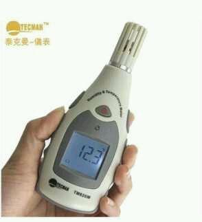
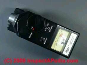
19 Sensitivity Meter 22/02/
20 Threshold Threshold is the smallest measurable input, below which no output change can be identified. While specifying threshold, manufactures give the first detectable output change. Range or span The minimum and maximum values of a quantity for which an instrument is designed to measure is called its range or span. Sometimes the accuracy is specified in terms of range or span of an instrument. 22/02/
21 Linearity Linearity is defined as the ability of an instrument to reproduce its input linearly. Linearity is simply a measure of the maximum deviation of the calibration points from the ideal straight line. Linearity is defined as, linearity=maximum deviation of o/p from idealized straight line Actual readings 22/02/
22 Resolution Resolution is the smallest detectable incremental change of input parameter that can be detected in the output signal. Resolution can be expressed either as a proportion of the full-scale reading or in absolute terms. For example, if a LVDT sensor measures a displacement up to 20 mm and it provides an output as a number between 1 and 100 then the resolution of the sensor device is 0.2 mm. 22/02/
23 Dynamic Characteristics Instruments rarely respond to the instantaneous changes in the measured variables.their response is slow or sluggish due to mass, thermal capacitance, electrical capacitance, inductance etc. sometimes, even the instrument has to wait for some time till, the response occurs. These type of instruments are normally used for the measurement of quantities that fluctuate with time.. The behavior of such a system, where as the input varies from instant to instant, the output also varies from instant to instant is called as dynamic response of the system Hence, the dynamic behaviour of the system is also important as the static behaviour. 22/02/
24 The dynamic characteristics of a measurement system are: 1) Speed of response 2) Fidelity 3) Lag 4) Dynamic error 22/02/

25 Speed of response It is defined as the rapidity with which an instrument, responds to the changes in the measured quantity. It shows how active and fast the system is. Speed measuring instruments:- 22/02/
26 Fidelity It is defined as the degree to which a measurement system is capable of faithfully reproducing the changes in input, without any dynamic error. 22/02/
27 Lag Every system requires its own time to respond to the changes in input. This time is called as lag. It is defined as the retardation or delay, in the response of a system to the changes in the input. The lags are of two types: 1. Retardation lag: As soon as there is a changes in the measured quantity, the measurement system begins to respond. 2. Time delay: The response of the measurement system starts after a dead time, once the input is applied. They cause dynamic error. 22/02/
28 EXAMPLE OF DYNAMIC CHARACTERISTICS Response from a 2 nd order instrument: Output 100% 90% 10% tr Time 22/02/
29 Response from a 2 nd order instrument: 1. Rise Time ( tr ) Time taken for the output to rise from 10% to 90 % of the steady state value. 2. Settling time (ts) Time taken for output to reach a steady state value. 3. Response time Time taken to reach first peak of oscillation. 22/02/
30 Basic Principle of Sensor / Transduction Measuring Parameter Conversion Device Useful Signal Displacement, Temperature, Pressure etc. Voltage, current, capacitance Sensor is a device that when exposed to a physical phenomenon (temperature, displacement, force, etc.) produces a proportional output signal (electrical, mechanical, magnetic, etc.). Transducer is a device that converts one form of (energy) signal into another form of (energy) signal. 22/02/
31 Sensors Displacement sensors are basically used for the measurement of movement of an object. Position sensors are employed to determine the position of an object in relation to some reference point Proximity sensors are a type of position sensor and are used to trace when an object has moved with in particular critical distance of a transducer. Position sensors 1) Potentiometer (Rotary and Linear) 2) LVDT 3) Encoder 22/02/
32 Detail classification of sensors in view of their applications in manufacturing is as follows. A. Displacement, position and proximity sensors Potentiometer Strain-gauged element Capacitive element Differential transformers Eddy current proximity sensors Inductive proximity switch Optical encoders Pneumatic sensors Proximity switches (magnetic) Hall effect sensors 22/02/
33 B. Velocity and motion Incremental encoder Tachogenerator Pyroelectric sensors C. Force Strain gauge load cell D. Fluid pressure Diaphragm pressure gauge Capsules, bellows, pressure tubes Piezoelectric sensors Tactile sensor 22/02/
34 E.Liquid flow Orifice plate Turbine meter F. Liquid level Floats Differential pressure G. Temperature Bimetallic strips Resistance temperature detectors Thermistors Thermo-diodes and transistors Thermocouples Light sensors Photo diodes Photo resistors 22/02/
35 Potentiometer A rotary potentiometer is a variable resistance device that can be used to measure angular position Through voltage division the change in resistance can be used to create an output voltage that is directly proportional to the input displacement. 22/02/

36 Potentiometers operated by a mechanism can be used as position transducer for example, in a joystick Potentiometers consist of a resistive element, a sliding contact (wiper) that moves along the element, making good electrical contact with one part of it, electrical terminals at each end of the element, a mechanism that moves the wiper from one end to the other, and a housing containing the element and wiper. 22/02/

37 Rotary Potentiometer 22/02/
38 Linear Potentiometer The linear potentiometer consist of resistance elements with number of turns of wire wound around non conducting bar together with a sliding contact. Sliding contact is called as wiper. 22/02/
39 Application of Potentiometer These sensors are primarily used in the control systems with a feedback loop to ensure that the moving member or component reaches its commanded position. These are typically used in machine-tool controls, elevators, liquid-level assemblies, forklift trucks, automobile throttle controls. In manufacturing, these are used in control of injection molding machines, woodworking machinery, printing, spraying, robotics etc. 22/02/


40 LVDT A reliable and accurate sensing device that converts linear position or motion to a proportional electrical output. 22/02/
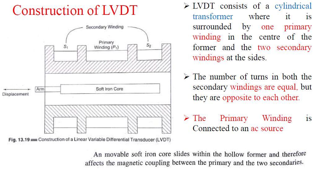
41 22/02/
42 22/02/
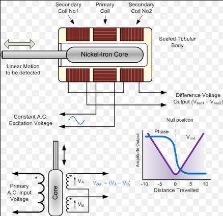
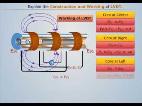
43 LVDT Operation If the core at the center, V 1 =V 2, V o =0 When the core is away from center toward S 1, V 1 is greater than V 2 and the output voltage V o will have the polarity V 1. When the core is away from center toward S 2, V 2 is greater than V 1 and the output voltage V o will have the polarity V 2. 22/02/
44 22/02/
45 22/02/
46 22/02/
47 22/02/
48 Applications of LVDT sensors Measurement of spool position in a wide range of servo valve applications To provide displacement feedback for hydraulic cylinders To control weight and thickness of medicinal products viz. tablets or pills For automatic inspection of final dimensions of products being packed for dispatch To measure distance between the approaching metals during Friction welding process To continuously monitor fluid level as part of leak detection system To detect the number of currency bills dispensed by an ATM 22/02/
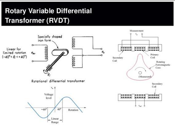
49 Rotary variable differential trandformer It is a type of electrical transformer used for measuring angular displacement It is an electromechanical transducer that provides a variable alternating current (AC) output voltage that is linearly proportional to the angular displacement of its input shaft. When energized with a fixed AC source, the output signal is linear within a specified range over the angular displacement. RVDT is used to measure rotational angles and operates under the same principles as the LVDT sensor. Whereas the LVDT uses a cylindrical iron core, the RVDT uses a rotary ferromagnetic core. 22/02/
50 22/02/
51 Optical encoders Optical encoders provide digital output as a result of linear / angular displacement. These are widely used in the Servo motors to measure the rotation of shafts. Any transducer that generates a coded reading of a measurement can be termed an encoder Shaft Encoders are digital transducers that are used for measuring angular displacements and velocities. 22/02/

52 Shaft Encoders can be classified into two categories depending on the nature and method of interpretation of the output: 1. Incremental Encoders 2. Absolute Encoders 22/02/

53 Construction And Working 22/02/
54 22/02/
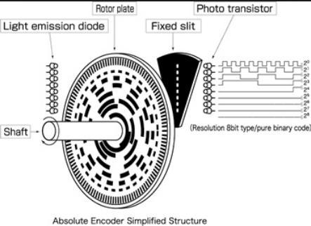
55 Working Principle Elements of the Optical Encoder The optical encoder uses an opaque disk (code disk) that has one or more circular tracks, with some arrangement of identical transparent windows (slits) in each track. A parallel beam of light (e.g., from a set of light-emitting diodes) is projected to all tracks from one side of the disk. The transmitted light is picked off using a bank of photosensors on the other side of the disk that typically has one sensor for each track. The light sensor could be a silicon photodiode, a phototransistor, or a photovoltaic cell. 22/02/
56 Since the light from the source is interrupted by the opaque areas of the track, the output signal from the probe is a series of voltage pulses. This signal can be interpreted to obtain the angular position and angular velocity of the disk. Figure shows the construction of an optical encoder. It comprises of a disc with three concentric tracks of equally spaced holes. Three light sensors are employed to detect the light passing thru the holes. These sensors produce electric pulses which give the angular displacement of the mechanical element e.g. shaft on which the Optical encoder is mounted. 22/02/
57 The inner track has just one hole which is used locate the home position of the disc. The holes on the middle track offset from the holes of the outer track by one-half of the width of the hole. This arrangement provides the direction of rotation to be determined. 22/02/
58 Incremental Encoder Incremental encoder disk requires only one primary track that has equally spaced and identical window (pick-off) areas. The window area is equal to the area of the interwindow gap. Usually, a reference track that has just one window is also present in order to generate a pulse (known as the index pulse) to initiate pulse counting for angular position m an incremental encoder requires additional electronics (typically a PLC, counter, or drive) to count pulses and convert the data into speed or motion measurement and to detect complete revolutions. 22/02/
59 22/02/
60 Absolute encoder absolute encoder disks have several rows of tracks, equal in number to the bit size of the output data word. Furthermore, the track windows are not equally spaced but are arranged in a specific pattern on each track so as to obtain a binary code (or gray code) for the output data from the transducer. 22/02/

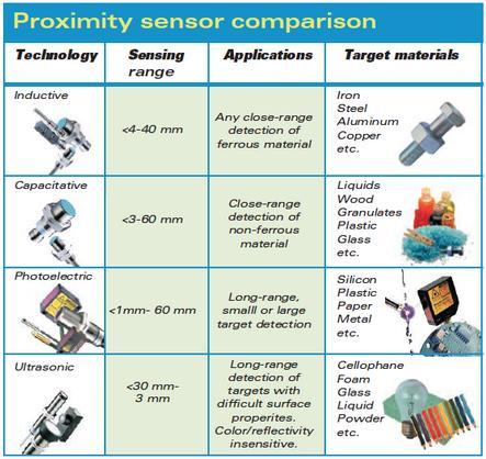
61 Proximity sensors A proximity sensor detects an objects when the object approaches within the detection range and boundary of the sensor. Proximity sensors include all sensor that perform non contact detection in comparison to sensors such as limit switch, that detects the object by physically contacting them. Proximity sensors are used in various processes of manufacturing for detecting the approach of metal and non metal objects. Two types: 1.Inductive proximity sensors 2.Capacitive proximity sensors 22/02/

62 Inductive proximity sensors eddy current proximity sensors are used to detect nonmagnetic but conductive materials. They comprise of a coil, an oscillator, a detector and a triggering circuit. 22/02/
63 Figure shows the construction of eddy current proximity switch. When an alternating current is passed thru this coil, an alternative magnetic field is generated. If a metal object comes in the close proximity of the coil, then eddy currents are induced in the object due to the magnetic field. These eddy currents create their own magnetic field which distorts the magnetic field responsible for their generation. As a result, impedance of the coil changes and so the amplitude of alternating current. This can be used to trigger a switch at some pre-determined level of change in current. Eddy current sensors are relatively inexpensive, available in small in size, highly reliable and have high sensitivity for small displacements. 22/02/
64 Applications of eddy current proximity sensors Automation requiring precise location Machine tool monitoring Final assembly of precision equipment such as disk drives Measuring the dynamics of a continuously moving target, such as a vibrating element, Drive shaft monitoring Vibration measurements 22/02/
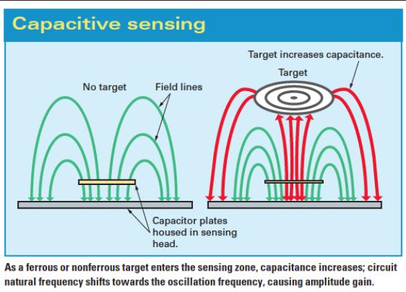
65 Capacitive proximity sensor Capacitive proximity sensors are similar to inductive proximity sensors. The main difference between the two types is that capacitive proximity sensors produce an electrostatic field instead of an electromagnetic field. Capacitive proximity switches will sense metal as well as nonmetallic materials such as paper, glass, liquids, and cloth. 22/02/
66 22/02/
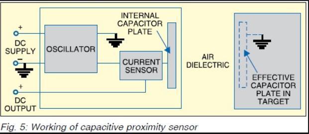
67 The sensing surface of a capacitive sensor is formed by two concentrically shaped metal electrodes of an unwound capacitor. When an object nears the sensing surface it enters the electrostatic field of the electrodes and changes the capacitance in an oscillator circuit. As a result, the oscillator begins oscillating. The trigger circuit reads the oscillator s amplitude and when it reaches a specific level the output state of the sensor changes. As the target moves away from the sensor the oscillator s amplitude decreases, switching the sensor output back to its original state. 22/02/
68 Capacitive proximity sensor Capacitive sensors depend on the dielectric constant of the target. The larger the dielectric number of a material the easier it is to detect. 22/02/
69 22/02/
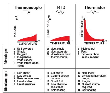
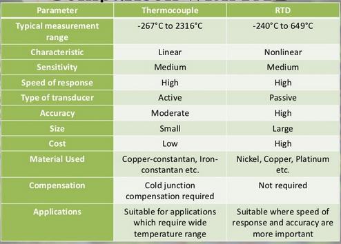
70 Temperature measurement 3 basic types 1. Thermocouple 2. RTD (resistance temperature detector) 3. Thermistor 22/02/
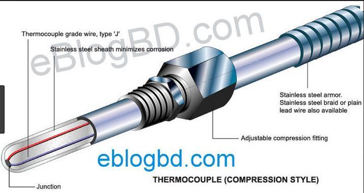
71 Thermocouple Thermocouple is a device used for the measurement of temperature. It can be even considered as a sensor for the measurement of temperature. 22/02/
72 Working Principle The junction of two dissimilar metals forms a thermocouple. When the two junctions are at different temperatures, a voltage is developed across the junction. By measuring the voltage difference between the two junctions, the difference in temperature between the two can be calculated. If the temperature of one junction is known and the voltage difference is measured, then the temperature of the second junction can be calculated. 22/02/
73 The working principle of thermocouple is based on three effects, discovered by Seebeck, Peltier and Thomson. They are as follows: 1) Seebeck effect: The Seebeck effect states that when two different or unlike metals are joined together at two junctions, an electromotive force (emf) is generated at the two junctions. The amount of emf generated is different for different combinations of the metals. 2) Peltier effect: When a electric current crosses a junction between two dissimilar metals, one junction get heated up and another will evolved the heat(cold junction) 22/02/
74 22/02/
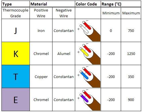
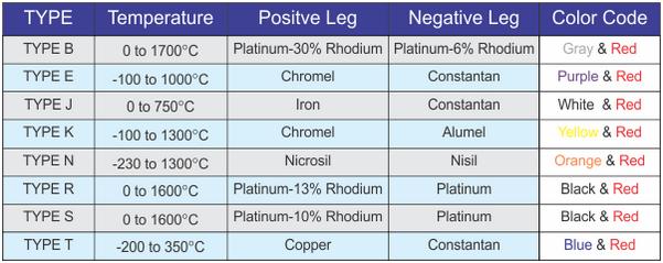
75 Types of thermocouples 1.Type E 2.Type J 3. Type K 4.Type M 5. Type N 6. Type T 7. Type B 8. Type R 9. Type S 22/02/
76 22/02/
77 22/02/
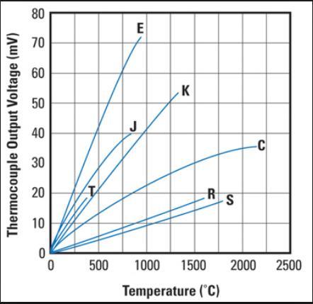
78 Characteristics 22/02/
.")
79 Thermistors Thermistor or thermal resistor is a hard, ceramiclike electronic semiconductor, commonly made from a mixture of metallic oxide materials. Have a very large negative resistance coefficient (i.e., an increase in T by 1 C yields a decrease of 5% in resistance). 22/02/

80 RTD: Resistance Temperature Detectors Platinum is most commonly used for precision resistance thermometers because it is stable, resists corrosion, is easily workable, has a high temp melting point, and can be obtained to a high degree of purity. Simple and stable resistance-temperature relationship. Platinum is sensitive to strain; bending the sensor can change the resistance. 22/02/
81 The RTD wire is a pure material, typically platinum, nickel, or copper. The material has an accurate resistance/temperature relationship which is used to provide an indication of temperature. As RTD elements are fragile, they are often housed in protective probes. RTDs, which have higher accuracy and repeatability, are slowly replacing thermocouples in industrial applications below 600 C. 22/02/
82 22/02/
83 22/02/


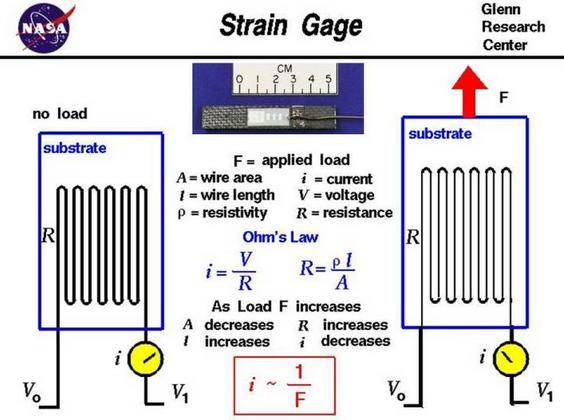
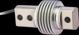
84 Load Cells A load cell is a transducer that is used to convert a force into electrical signal. The most common type is a strain gauge load cell. 22/02/
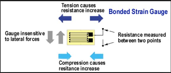
85 What Is It? Strain Gauge A Strain Gauge is a device used to measure the strain of an object. The most common type of strain gauge consists of an insulating flexible backing which supports a metallic foil pattern. 22/02/

86 Strain Gauge Resistance R =ρ l A 1. Strain Gauge under tension. Resistance goes up. 2. Strain Gauge under compression. Resistance goes down. 22/02/
87 22/02/
88 22/02/

89 Strain Gauge How Does It Work? The gauge is attached to the object by a suitable adhesive. As the object is deformed, the foil is deformed, causing its electrical resistance to change. The resistance change is commonly measured using a Wheatstone bridge. 22/02/
90 Wheatstone Bridge A Wheatstone Bridge is an electrical circuit. Used in a load cell to measure an overall change in resistance. Increases sensitivity and reduces the affects of temperature. + - VEX R1 R2 V0 R4 R3 22/02/
91 Load Cells Applications Scales Weighbridge Force Gauges Torque Gauges 22/02/


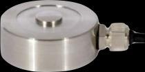

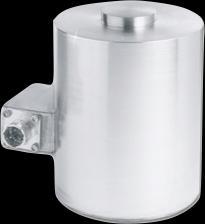

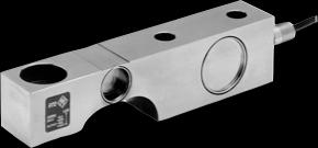


92 Load Cells Types S Type Button Canister Shear Beam 22/02/
93 Electro magnetic flow sensor 22/02/
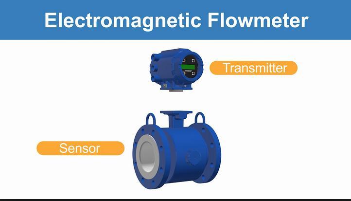
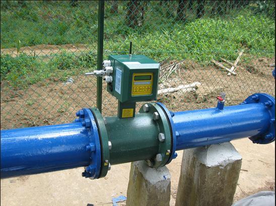
94 22/02/
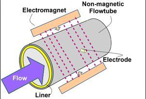
95 Working Principle The operation of a magnetic flowmeter or magmeter is based upon Faraday's Law, which states that the voltage induced across any conductor as it moves at right angles through a magnetic field is proportional to the velocity of that conductor. This law states that e= B l v In of electromagnetic flowmeters, the conductor is the liquid flowing through the pipe, e = B D v 22/02/
96 In Magmeter magnetic field is generated using Electromagnets. The magnetic field has to permeate the process liquid through the tube wall, and for that reason the measuring tube should not have ferromagnetic properties. The electrodes are in direct contact with the process liquid. Their material needs to be adequately resistant to corrosion and must allow good electrical contact with the process liquid. The most commonly used electrode materials are stainless steel grades, Cr-Ni alloys, platinum, tantalum, titanium zirconium. 22/02/

97 Brushless DC electric motor. Stepper Motor Division of full rotation. Divided to equal steps. Motor position commanded to move. Hold at any of steps without an open loop controller 22/02/
98 Working principle A stepper motor is an electromechanical device which converts electrical pulses into discrete mechanical movements. The shaft or spindle of a stepper motor rotates indiscrete step increments when electrical command pulses are applied to it in the proper sequence. The motors rotation has several direct relationships to these applied input pulses. The sequence of the applied pulses is directly related to the direction of motor shafts rotation. The speed of the motor shafts rotation is directly related to the frequency of the input pulses and the length of rotation is directly related to the number of input pulses applied 22/02/
99 Terminology Step Angle the angle by which the rotor of a stepper motor rotates for each command pulse. Step angle, β = {(Ns-Nr)*360 }/(Ns*Nr), where Ns is no. of stator teeth & Nr is no. of rotor teeth Resolution the number of steps needed to complete one revolution of shaft. Resolution = 360 /β The speed of the motor shaft is, n = (β*f)/360 rps, where f is stepping frequency(or pulse rate). Detent torque the torque required to hold the rotor stationary while power is switched off. Holding torque the torque required to deflect the rotor one full step at standstill. 22/02/


100 The 3 Types Of Motors? 1. Variable Reluctance Stepper 2. Permanent Magnet Stepper 3. Hybrid Synchronous Stepper 22/02/
101 Types Permanent magnet stepper motor uses a permanent magnet in the rotor. Variable reluctance stepper motor have a plain iron rotor and operate based on the principle that minimum reluctance occurs with minimum gap, hence the rotor points are attracted toward the stator magnet poles. Hybrid stepper motor use a combination of PM and VR techniques to achieve maximum power in a small package size. 22/02/

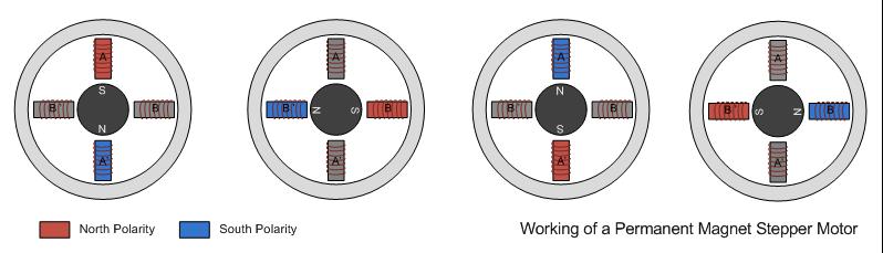
102 Permanent magnet stepper Permanent magnet (PM) in the rotor operate on the attraction or repulsion b/w the rotor PM and the stator electromagnets. The rotor is made of a permanent-magnet material like magnetically hard ferrite. The stator has projecting poles but the rotor is cylindrical and has radially magnetized permanent magnet. 22/02/
103 PM Stepper Motor Working When a particular stator phase is energised, the rotor magnetic poles move into alignment with the excited stator poles. The stator windings 1 and 2 can be excited with either polarity current. When phase 1 is excited with positive current, the rotor aligns itself in a vertical position. If excitation is now switched to phase 2 the rotor rotates by full step of 90 in clockwise direction. Next, when phase 1 is excited with negative current, the rotor turns through another 90 degree in CW direction. 22/02/

104 22/02/
105 22/02/

106 Comparison 22/02/
107 Applications They are commonly used in watches and old electric meters They are used in wide variety 1. In Industry As - Drilling Machine, - Grinder, - Laser Cutting, - Conveyor;& - Assembly Lines. 2. In computer Peripherals As - Printer, - Plotter, - Tape Reader, - Card Reader;& - Copy Machines. 3. In Business As - Banking systems;& - Automatic typewriters. 4. In Motion Control and Robotics As - Silicon Processing;& - I.C. Bonding. 22/02/
108 What is servo motor? A servomotor is a rotary actuator that allows for precise control of angular position, velocity and acceleration. It consists of a suitable motor coupled to a sensor for position feedback. It also requires a relatively sophisticated controller, often a dedicated module designed specifically for use with servomotors. Servomotors are not a specific class of motor although the term servomotor is often used to refer to a motor suitable for use in a closed-loop control system. Servomotors are used in applications such as robotics, CNC machinery or automated manufacturing. 22/02/
109 Motors can be either AC or DC Can be of 1 phase or 3 phase. DC motors can be brushed or brushless. Brushless DC motors are more expensive, drives are more complex, but are more reliable and maintenance free. Feedback device for servomotors is typically an encoder or resolver built into the motor frame. Control circuitry is a motion controller (generates motion) and a drive to supply power to the motor 22/02/
110 22/02/
111 There are mainly two types of servo-motors, 1)AC Servo-motor 2)DC Servo-motor AC servo-motors are generally preferred for low power use and for high-power use DC servomotors are preferred because they operate more efficiently than comparable to AC servo-motors DC Servo-motor: Unlike large industrial motors, dc servomotors are not used for continuous energy conversion. The basic operating principle is same as other electromagnetic motors. 22/02/


112 Types of servo motors AC servo motor Dc servo motor Continuous rotation servo motor Linear servo motor 22/02/
113 contactor Layout of servo mechanism PLC (transistor type) Power source Servo drive Servo motor Load 22/02/
114 22/02/
115 Working principle of DC servomotor In DC operation, servomotors are usually responds to error signal abruptly and accelerate the load quickly. A DC servo motor is actually an assembly of four separate components, namely: 1. DC motor 2.Gear assembly 3. Position-sensing device 4. Control circuit. 22/02/
116 The motors which are utilized as DC servo motors, generally have separate DC source for field winding and armature winding. The control can be archived either by controlling the field current or armature current. Field control has some specific advantages over armature control and on the other hand armature control has also some specific advantages over field control. Which type of control should be applied to the DC servo motor, is being decided depending upon its specific applications. 22/02/

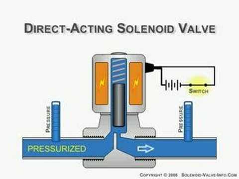
117 Solenoid valves Turning Electrical Power into Mechanical Work How solenoid works 1. Apply Current 2. Magnetic Field Builds 3. Stop and Plunger Become Attracting Magnets 4. Magnetic Force Drives Plunger to Stop 22/02/

118 Solenoid Valve 22/02/
119 working It is a valve which is used to control the action of the air movement. Solenoid valve is used to mix and distribute the air by the valve that generates the air. The valve is controlled by using the electric current with the help of solenoid. There are two port valves, three port valves and multi port valve. 22/02/
120 22/02/
121 Components Magnetic Coil Valve Stem Valve Sheet Inlet Outlet Plunger Breakaway Pin. 22/02/
122 Application These are applicable in controlling the hydraulic action. These are used for mixing and distributing the air. These are applicable in RO purifier. These are applicable in the dust collectors. 22/02/
5. Transducers Definition and General Concept of Transducer Classification of Transducers
 5.1. Definition and General Concept of Definition The transducer is a device which converts one form of energy into another form. Examples: Mechanical transducer and Electrical transducer Electrical A
Electronic Systems - B1 23/04/ /04/ SisElnB DDC. Chapter 2
 Politecnico di Torino - ICT school Goup B - goals ELECTRONIC SYSTEMS B INFORMATION PROCESSING B.1 Systems, sensors, and actuators» System block diagram» Analog and digital signals» Examples of sensors»
ELECTRONIC SYSTEMS. Introduction. B1 - Sensors and actuators. Introduction
 Politecnico di Torino - ICT school Goup B - goals ELECTRONIC SYSTEMS B INFORMATION PROCESSING B.1 Systems, sensors, and actuators» System block diagram» Analog and digital signals» Examples of sensors»
ECET 211 Electric Machines & Controls Lecture 4-2 Motor Control Devices: Lecture 4 Motor Control Devices
 ECET 211 Electric Machines & Controls Lecture 4-2 Motor Control Devices: Part 3. Sensors, Part 4. Actuators Text Book: Electric Motors and Control Systems, by Frank D. Petruzella, published by McGraw Hill,
9/28/2010. Chapter , The McGraw-Hill Companies, Inc.
 Chapter 4 Sensors are are used to detect, and often to measure, the magnitude of something. They basically operate by converting mechanical, magnetic, thermal, optical, and chemical variations into electric
Introduction to Measurement Systems
 MFE 3004 Mechatronics I Measurement Systems Dr Conrad Pace Page 4.1 Introduction to Measurement Systems Role of Measurement Systems Detection receive an external stimulus (ex. Displacement) Selection measurement
Sensors. Chapter 3. Storey: Electrical & Electronic Systems Pearson Education Limited 2004 OHT 3.1
 Sensors Chapter 3 Introduction Describing Sensor Performance Temperature Sensors Light Sensors Force Sensors Displacement Sensors Motion Sensors Sound Sensors Sensor Interfacing Storey: Electrical & Electronic
VARIABLE INDUCTANCE TRANSDUCER
 VARIABLE INDUCTANCE TRANSDUCER These are based on a change in the magnetic characteristic of an electrical circuit in response to a measurand which may be displacement, velocity, acceleration, etc. 1.
Introduction. ELCT903, Sensor Technology Electronics and Electrical Engineering Department 1. Dr.-Eng. Hisham El-Sherif
 Introduction In automation industry every mechatronic system has some sensors to measure the status of the process variables. The analogy between the human controlled system and a computer controlled system
Position Sensors. The Potentiometer.
 Position Sensors In this tutorial we will look at a variety of devices which are classed as Input Devices and are therefore called "Sensors" and in particular those sensors which are Positional in nature
EE T55 MEASUREMENTS AND INSTRUMENTATION
 EE T55 MEASUREMENTS AND INSTRUMENTATION UNIT V: TRANSDUCERS Temperature transducers-rtd, thermistor, Thermocouple-Displacement transducer-inductive, capacitive, LVDT, Pressure transducer Bourdon tube,
Electronic Instrumentation and Measurements
 Electronic Instrumentation and Measurements A fundamental part of many electromechanical systems is a measurement system that composed of four basic parts: Sensors Signal Conditioning Analog-to-Digital-Conversion
1. Explain in detail the constructional details and working of DC motor.
 DHANALAKSHMI SRINIVASAN INSTITUTE OF RESEARCH AND TECHNOLOGY, PERAMBALUR DEPT OF ECE EC6352-ELECTRICAL ENGINEERING AND INSTRUMENTATION UNIT 1 PART B 1. Explain in detail the constructional details and
PART 2 - ACTUATORS. 6.0 Stepper Motors. 6.1 Principle of Operation
 6.1 Principle of Operation PART 2 - ACTUATORS 6.0 The actuator is the device that mechanically drives a dynamic system - Stepper motors are a popular type of actuators - Unlike continuous-drive actuators,
Shaft encoders are digital transducers that are used for measuring angular displacements and angular velocities.
 Shaft Encoders: Shaft encoders are digital transducers that are used for measuring angular displacements and angular velocities. Encoder Types: Shaft encoders can be classified into two categories depending
Synchronous Machines Study Material
 Synchronous machines: The machines generating alternating emf from the mechanical input are called alternators or synchronous generators. They are also known as AC generators. All modern power stations
Load Cells, LVDTs and Thermocouples
 Load Cells, LVDTs and Thermocouples Introduction Load cells are utilized in nearly every electronic weighing system while LVDTs are used to measure the displacement of a moving object. Thermocouples have
IT.MLD900 SENSORS AND TRANSDUCERS TRAINER. Signal Conditioning
 SENSORS AND TRANSDUCERS TRAINER IT.MLD900 The s and Instrumentation Trainer introduces students to input sensors, output actuators, signal conditioning circuits, and display devices through a wide range
Electro-hydraulic Servo Valve Systems
 Fluidsys Training Centre, Bangalore offers an extensive range of skill-based and industry-relevant courses in the field of Pneumatics and Hydraulics. For more details, please visit the website: https://fluidsys.org
Advanced Measurements
 Albaha University Faculty of Engineering Mechanical Engineering Department Lecture 3: Position, Displacement, and Level Ossama Abouelatta o_abouelatta@yahoo.com Mechanical Engineering Department Faculty
Continuous Sensors Accuracy Resolution Repeatability Linearity Precision Range
 Continuous Sensors A sensor element measures a process variable: flow rate, temperature, pressure, level, ph, density, composition, etc. Much of the time, the measurement is inferred from a second variable:
Computer Numeric Control
 Computer Numeric Control TA202A 2017-18(2 nd ) Semester Prof. J. Ramkumar Department of Mechanical Engineering IIT Kanpur Computer Numeric Control A system in which actions are controlled by the direct
Feedback Devices. By John Mazurkiewicz. Baldor Electric
 Feedback Devices By John Mazurkiewicz Baldor Electric Closed loop systems use feedback signals for stabilization, speed and position information. There are a variety of devices to provide this data, such
combine regular DC-motors with a gear-box and an encoder/potentiometer to form a position control loop can only assume a limited range of angular
 Embedded Control Applications II MP10-1 Embedded Control Applications II MP10-2 week lecture topics 10 Embedded Control Applications II - Servo-motor control - Stepper motor control - The control of a
As before, the speed resolution is given by the change in speed corresponding to a unity change in the count. Hence, for the pulse-counting method
 Velocity Resolution with Step-Up Gearing: As before, the speed resolution is given by the change in speed corresponding to a unity change in the count. Hence, for the pulse-counting method It follows that
An Instrumentation System
 Transducer As Input Elements to Instrumentation System An Instrumentation System Input signal (measurand) electrical or non-electrical Input Device Signal Conditioning Circuit Output Device? -amplifier
Industrial Sensors. Proximity Mechanical Optical Inductive/Capacitive. Position/Velocity Potentiometer LVDT Encoders Tachogenerator
 Proximity Mechanical Optical Inductive/Capacitive Position/Velocity Potentiometer LVDT Encoders Tachogenerator Force/Pressure Vibration/acceleration Industrial Sensors 1 Definitions Accuracy: The agreement
Unit I. Introduction to Sensors & Actuators Syllabus
 Mechatronics Introduction to Sensors & Actuators Unit I. Introduction to Sensors & Actuators Syllabus Introduction to Mechatronics, Measurement characteristics: - Static and Dynamic Sensors: Position Sensors:
Basic NC and CNC. Dr. J. Ramkumar Professor, Department of Mechanical Engineering Micro machining Lab, I.I.T. Kanpur
 Basic NC and CNC Dr. J. Ramkumar Professor, Department of Mechanical Engineering Micro machining Lab, I.I.T. Kanpur Micro machining Lab, I.I.T. Kanpur Outline 1. Introduction to CNC machine 2. Component
Sensors & transducers
 Sensors & transducers Prof. H. Arya DEPT. OF AEROSPACE ENGINEERING IIT BOMBAY Sensors Sensors - A device that produces an output signal for the purpose of sensing a physical phenomenon. Sensors are also
COURSE INFORMATION. Course Prefix/Number: EET 231. Lecture Hours/Week: 3.0 Lab Hours/Week: 3.0 Credit Hours/Semester: 4.0
 COURSE INFORMATION Course Prefix/Number: EET 231 Course Title: Industrial Electronics Lecture Hours/Week: 3.0 Lab Hours/Week: 3.0 Credit Hours/Semester: 4.0 VA Statement/Distance Learning Attendance Textbook
UNIT 10 INTRODUCTION TO TRANSDUCERS AND SENSORS
 UNIT 10 INTRODUCTION TO TRANSDUCERS AND SENSORS Structure 10.1 Introduction Objectives 10.2 Active and Passive Sensors 10.3 Basic Requirements of a Sensor/Transducer 10.4 Discrete Event Sensors 10.4.1
ACTUATORS AND SENSORS. Joint actuating system. Servomotors. Sensors
 ACTUATORS AND SENSORS Joint actuating system Servomotors Sensors JOINT ACTUATING SYSTEM Transmissions Joint motion low speeds high torques Spur gears change axis of rotation and/or translate application
Job Sheet 2 Servo Control
 Job Sheet 2 Servo Control Electrical actuators are replacing hydraulic actuators in many industrial applications. Electric servomotors and linear actuators can perform many of the same physical displacement
Sensors and Sensing Motors, Encoders and Motor Control
 Sensors and Sensing Motors, Encoders and Motor Control Todor Stoyanov Mobile Robotics and Olfaction Lab Center for Applied Autonomous Sensor Systems Örebro University, Sweden todor.stoyanov@oru.se 13.11.2014
Power systems Protection course
 Al-Balqa Applied University Power systems Protection course Department of Electrical Energy Engineering 1 Part 5 Relays 2 3 Relay Is a device which receive a signal from the power system thought CT and
ECET 211 Electrical Machines and Controls
 ECET 211 Electrical Machines and Controls 2016/4/27 Class Review and Wrapping Up Comprehensive Exam, Friday, 1:00-3:00 PM, May 6, 2016 Close books/allow 1-page (8 x 11 and ½) hand-written review note,
Sensors (Transducer) Introduction By Sintayehu Challa
 Introduction By Sintayehu Challa") Sensors (Transducer) Introduction What are Sensors? Basically the quantities to be measured are Non-Electrical quantities such as temperature, pressure,displacement,humidity, fluid flow, speed etc, but
Sensors (Transducer) Introduction What are Sensors? Basically the quantities to be measured are Non-Electrical quantities such as temperature, pressure,displacement,humidity, fluid flow, speed etc, but
M.D. Singh J.G. Joshi MECHATRONICS
 M.D. Singh J.G. Joshi MECHATRONICS MECHATRONICS MECHATRONICS M.D. SINGH Formerly Principal Sagar Institute of Technology and Research Bhopal J.G. JOSHI Lecturer Department of Electronics and Telecommunication
Page ENSC387 - Introduction to Electro-Mechanical Sensors and Actuators: Simon Fraser University Engineering Science
 Motor Driver and Feedback Control: The feedback control system of a dc motor typically consists of a microcontroller, which provides drive commands (rotation and direction) to the driver. The driver is
L E C T U R E R, E L E C T R I C A L A N D M I C R O E L E C T R O N I C E N G I N E E R I N G
 P R O F. S L A C K L E C T U R E R, E L E C T R I C A L A N D M I C R O E L E C T R O N I C E N G I N E E R I N G G B S E E E @ R I T. E D U B L D I N G 9, O F F I C E 0 9-3 1 8 9 ( 5 8 5 ) 4 7 5-5 1 0
Ch 5 Hardware Components for Automation
 Ch 5 Hardware Components for Automation Sections: 1. Sensors 2. Actuators 3. Analog-to-Digital Conversion 4. Digital-to-Analog Conversion 5. Input/Output Devices for Discrete Data Computer-Process Interface
MECE 3320 Measurements & Instrumentation. Data Acquisition
 MECE 3320 Measurements & Instrumentation Data Acquisition Dr. Isaac Choutapalli Department of Mechanical Engineering University of Texas Pan American Sampling Concepts 1 f s t Sampling Rate f s 2 f m or
M.Tech.: Mechatronics Product Design. Lecture Notes -1 Introduction of Mechatronics Product Design
 M.Tech.: Mechatronics Product Design Lecture Notes -1 Introduction of Mechatronics Product Design Mechatronics is a concept of Japanese origin (1970 s) and can be defined as the combination of Mechanical
Chapter 5 Electric Logic Sensors and Actuators
 Chapter 5: Electric logic sensors and actuators -IE337 Chapter 5 Electric Logic Sensors and Actuators 1 5.1 Introduction to Electric Logic Sensors and Actuators Electric sensors and actuators can be classified
CRN: MET-487 Instrumentation and Automatic Control June 28, 2010 August 5, 2010 Professor Paul Lin
 CRN: 32030 MET-487 Instrumentation and Automatic Control June 28, 2010 August 5, 2010 Professor Paul Lin Course Description: Class 2, Lab 2, Cr. 3, Junior class standing and 216 Instrumentation for pressure,
Mechatronics Chapter Sensors 9-1
 MEMS1049 Mechatronics Chapter Sensors 9-1 Proximity sensors and Switches Proximity sensor o o o A proximity sensor is a sensor able to detect the presence of nearby objects without any physical contact.
09-2 EE 4770 Lecture Transparency. Formatted 12:49, 19 February 1998 from lsli
 09-1 09-1 Displacement and Proximity Displacement transducers measure the location of an object. Proximity transducers determine when an object is near. Criteria Used in Selection of Transducer How much
Department of Mechatronics Engineering
 Department of Mechatronics Engineering COURSES COVERED CONTROL SYSTEM POWER ELECTRONICS ELECTROMECHANICAL SYSTEM SENSORS AND INTRUMENTATION LAB SUPERVISOR: ENGR. MOEZ UL HASSAN NI ELVIS II The NI Educational
DC motor control using arduino
 DC motor control using arduino 1) Introduction: First we need to differentiate between DC motor and DC generator and where we can use it in this experiment. What is the main different between the DC-motor,
UNIVERSITY OF JORDAN Mechatronics Engineering Department Measurements & Control Lab Experiment no.1 DC Servo Motor
 UNIVERSITY OF JORDAN Mechatronics Engineering Department Measurements & Control Lab. 0908448 Experiment no.1 DC Servo Motor OBJECTIVES: The aim of this experiment is to provide students with a sound introduction
 Code No: M0326 /R07 Set No. 1 1. Define Mechatronics and explain the application of Mechatronics in CNC Machine tools and Computer Integrated Manufacturing (CIM). 2. (a) What are the various Filters that
Question Paper Code : B.E./B.Tech. DEGREE EXAMINATION, NOVEMBER/DECEMBER Third Semester. Electrical and Electronics Engineering
 Question Paper Code : 31391 B.E./B.Tech. DEGREE EXAMINATION, NOVEMBER/DECEMBER 2013. Third Semester Electrical and Electronics Engineering EE 2201/EE 33/EI 1202/10133 EE 302/080280016 MEASUREMENTS AND
Sensors and Sensing Motors, Encoders and Motor Control
 Sensors and Sensing Motors, Encoders and Motor Control Todor Stoyanov Mobile Robotics and Olfaction Lab Center for Applied Autonomous Sensor Systems Örebro University, Sweden todor.stoyanov@oru.se 05.11.2015
Assembly Language. Topic 14 Motion Control. Stepper and Servo Motors
 Assembly Language Topic 14 Motion Control Stepper and Servo Motors Objectives To gain an understanding of the operation of a stepper motor To develop a means to control a stepper motor To gain an understanding
PVA Sensor Specifications
 Position, Velocity, and Acceleration Sensors 24.1 Sections 8.2-8.5 Position, Velocity, and Acceleration (PVA) Sensors PVA Sensor Specifications Good website to start your search for sensor specifications:
MICROCONTROLLERS Stepper motor control with Sequential Logic Circuits
 PH-315 MICROCONTROLLERS Stepper motor control with Sequential Logic Circuits Portland State University Summary Four sequential digital waveforms are used to control a stepper motor. The main objective
PRESENTED BY HUMANOID IIT KANPUR
 SENSORS & ACTUATORS Robotics Club (Science and Technology Council, IITK) PRESENTED BY HUMANOID IIT KANPUR October 11th, 2017 WHAT ARE WE GOING TO LEARN!! COMPARISON between Transducers Sensors And Actuators.
Sensors for Mechatronics
 Sensors for Mechatronics Paul P.L Regtien Hertgelo The Netherlands AMSTERDAM BOSTON HEIDELBERG LONDON NEW YORK' OXFORD ELSEVIER PARIS SAN DIEGO SAN FRANCISCO SINGAPORE SYDNEY TOKYO Contents Preface xi
Sensors and Actuators Introduction to sensors
 Sensors and Actuators Introduction to sensors Sander Stuijk (s.stuijk@tue.nl) Department of Electrical Engineering Electronic Systems INDUCTIVE SENSORS (Chapter 3.4, 7.3) 3 Inductive sensors 4 Inductive
COVENANT UNIVERSITY NIGERIA TUTORIAL KIT OMEGA SEMESTER PROGRAMME: MECHANICAL ENGINEERING
 COVENANT UNIVERSITY NIGERIA TUTORIAL KIT OMEGA SEMESTER PROGRAMME: MECHANICAL ENGINEERING COURSE: MCE 527 DISCLAIMER The contents of this document are intended for practice and leaning purposes at the
Part 10: Transducers
 Part 10: Transducers 10.1: Classification of Transducers An instrument may be defined as a device or a system which is designed to maintain a functional relationship between prescribed properties of physical
Mechatronics System Design - Sensors
 Mechatronics System Design - Sensors Aim of this class 1. The functional role of the sensor? 2. Displacement, velocity and visual sensors? 3. An integrated example-smart car with visual and displacement
Developer Techniques Sessions
 1 Developer Techniques Sessions Physical Measurements and Signal Processing Control Systems Logging and Networking 2 Abstract This session covers the technologies and configuration of a physical measurement
Robot Sensors Introduction to Robotics Lecture Handout September 20, H. Harry Asada Massachusetts Institute of Technology
 Robot Sensors 2.12 Introduction to Robotics Lecture Handout September 20, 2004 H. Harry Asada Massachusetts Institute of Technology Touch Sensor CCD Camera Vision System Ultrasonic Sensor Photo removed
INSTRUMENTATION AND CONTROL TUTORIAL 3 SIGNAL PROCESSORS AND RECEIVERS
 INSTRUMENTATION AND CONTROL TUTORIAL 3 SIGNAL PROCESSORS AND RECEIVERS This tutorial provides an overview of signal processing and conditioning for use in instrumentation and automatic control systems.
1393 DISPLACEMENT SENSORS
 1393 DISPLACEMENT SENSORS INTRODUCTION While regular sensors detect the existence of objects, displacement sensors detect the amount of displacement when objects move from one position to another. Detecting
Lab Exercise 9: Stepper and Servo Motors
 ME 3200 Mechatronics Laboratory Lab Exercise 9: Stepper and Servo Motors Introduction In this laboratory exercise, you will explore some of the properties of stepper and servomotors. These actuators are
Figure 1.1 Mechatronic system components (p. 3)
") Figure 1.1 Mechatronic system components (p. 3) Example 1.2 Measurement System Digital Thermometer (p. 5) Figure 2.2 Electric circuit terminology (p. 13) Table 2.2 Resistor color band codes (p. 18) Figure
Figure 1.1 Mechatronic system components (p. 3) Example 1.2 Measurement System Digital Thermometer (p. 5) Figure 2.2 Electric circuit terminology (p. 13) Table 2.2 Resistor color band codes (p. 18) Figure
Lecture 5. In The Name of Allah. Instrumentation. Dr. Ali Karimpour Associate Professor Ferdowsi University of Mashhad
 In The Name of Allah Instrumentation Dr. Ali Karimpour Associate Professor Ferdowsi University of Mashhad Position Sensors Topics to be covered include: v v v v v v Introduction Resistive Displacement
Draw the symbol and state the applications of : 1) Push button switch 2) 3) Solenoid valve 4) Limit switch ( 1m each) Ans: 1) Push Button
 Push button switch 2) 3) Solenoid valve 4) Limit switch ( 1m each) Ans: 1) Push Button") Subject Code: 17641Model AnswerPage 1 of 16 Important suggestions to examiners: 1) The answers should be examined by key words and not as word-to-word as given in the model answer scheme. 2) The model
Subject Code: 17641Model AnswerPage 1 of 16 Important suggestions to examiners: 1) The answers should be examined by key words and not as word-to-word as given in the model answer scheme. 2) The model
Signal Conditioning Fundamentals for PC-Based Data Acquisition Systems
 Application Note 048 Signal Conditioning Fundamentals for PC-Based Data Acquisition Systems Introduction PC-based data acquisition (DAQ) systems and plugin boards are used in a very wide range of applications
Advanced Measurements
 Albaha University Faculty of Engineering Mechanical Engineering Department Lecture 5: Displacement measurement Ossama Abouelatta o_abouelatta@yahoo.com Mechanical Engineering Department Faculty of Engineering
Sensors and Transducers
 Sensors and Transducers Transducers-Transducer is a device which converts one form of energy into another form of energy. Electrical transducers are those which convert one form of energy into electrical
Chapter 8. Digital and Analog Interfacing Methods
 Chapter 8 Digital and Analog Interfacing Methods Lesson 16 MCU Based Instrumentation Outline Resistance and Capacitance based Sensor Interface Inductance based Sensor (LVDT) Interface Current based (Light
 VIDYARTHIPLUS - ANNA UNIVERSITY ONLINE STUDENTS COMMUNITY UNIT 1 DC MACHINES PART A 1. State Faraday s law of Electro magnetic induction and Lenz law. 2. Mention the following functions in DC Machine (i)
Chap. 5 Electronic Components and Sensing Devices
 1 Chap. 5 Electronic Components and Sensing Devices Today, practically all mechanical devices contain some sort of electronic components. The function of a product often relies on the integration of mechanical
PART A. 1. List the types of DC Motors. Give any difference between them. BTL 1 Remembering
 UNIT I DC MACHINES Three phase circuits, a review. Construction of DC machines Theory of operation of DC generators Characteristics of DC generators Operating principle of DC motors Types of DC motors
UNIT II MEASUREMENT OF POWER & ENERGY
 UNIT II MEASUREMENT OF POWER & ENERGY Dynamometer type wattmeter works on a very simple principle which is stated as "when any current carrying conductor is placed inside a magnetic field, it experiences
Relay Types and Applications Dr. Sasidharan Sreedharan
 O&M of Protection System and Relay Coordination Relay Types and Applications Dr. Sasidharan Sreedharan www.sasidharan.webs.com Detailed Schedule 2 SIMPLE RELAY Magnitude Rate of Change Phase Angle Direction
How to Select the Right Positioning Sensor Solution A WHITE PAPER
 How to Select the Right Positioning Sensor Solution A WHITE PAPER Published 10/1/2012 Today s machinery and equipment are continuously evolving, designed to enhance efficiency and built to withstand harsher
A COMPARISON STUDY OF THE COMMUTATION METHODS FOR THE THREE-PHASE PERMANENT MAGNET BRUSHLESS DC MOTOR
 A COMPARISON STUDY OF THE COMMUTATION METHODS FOR THE THREE-PHASE PERMANENT MAGNET BRUSHLESS DC MOTOR Shiyoung Lee, Ph.D. Pennsylvania State University Berks Campus Room 120 Luerssen Building, Tulpehocken
Actuators in Automatic Control System
 Actuators in Automatic Control System Measurement & Control Systems Transducers Measurement Process Actuators Data processing Requirement analyses Decision making Control actions CONTROL action requires
MODEL ANSWER WINTER 17 EXAMINATION 17414
 Important Instructions to examiners: 1) The answers should be examined by key words and not as word-to-word as given in the model answer scheme. 2) The model answer and the answer written by candidate
Step vs. Servo Selecting the Best
 Step vs. Servo Selecting the Best Dan Jones Over the many years, there have been many technical papers and articles about which motor is the best. The short and sweet answer is let s talk about the application.
Lecture 5. In The Name of Allah. Instrumentation. Dr. Ali Karimpour Associate Professor Ferdowsi University of Mashhad
 In The Name of Allah Instrumentation Dr. Ali Karimpour Associate Professor Ferdowsi University of Mashhad Position Sensors Topics to be covered include: v v v v v v Introduction Resistive Displacement
Tektronix AFG10022 Function Generator. Coming soon to B10: Sin, Square, Ramp, Swept, Arbitrary, Noise. Linear Actuators. Non-magnetized iron plunger
 4/19/18 Tektronix AFG10022 Function Generator Coming soon to B10: Sin, Square, Ramp, Swept, Arbitrary, Noise 508 Linear Actuators Solenoids (stationary coil) Non-magnetized iron plunger Iron always pulled
APPLICATION NOTE 695 New ICs Revolutionize The Sensor Interface
 Maxim > Design Support > Technical Documents > Application Notes > Sensors > APP 695 Keywords: high performance, low cost, signal conditioner, signal conditioning, precision sensor, signal conditioner,
Measurements & Instrumentation
 1 1 INTRODUCTION Measurements & Instrumentation Measurement defined as branch of engineering that deals with measuring devices that used to determine various parameters of a system or a process. It is
MEASUREMENT AND INSTRUMENTATION QUESTION BANK UNIT I INTRODUCTION. Part A
 MEASUREMENT AND INSTRUMENTATION QUESTION BANK UNIT I INTRODUCTION Part A 1. Define Standard deviation. 2. Why calibration of instrument is important? 3. What are the different calibration methodologies?
GOVERNMENT COLLEGE OF ENGINEERING, BARGUR
 1. Which of the following is the major consideration to evolve a good design? (a) Cost (b) Durability (c) Compliance with performance criteria as laid down in specifications (d) All of the above 2 impose
1. A transducer converts
 1. A transducer converts a. temperature to resistance b. force into current c. position into voltage d. one form of energy to another 2. Whose of the following transducers the output is a change in resistance?
Position and Velocity Sensors
 Position and Velocity Sensors Introduction: A third type of sensor which is commonly used is a speed or position sensor. Position sensors are required when the location of an object is to be controlled.
Lecture 3: Sensors, signals, ADC and DAC
 Instrumentation and data acquisition Spring 2010 Lecture 3: Sensors, signals, ADC and DAC Zheng-Hua Tan Multimedia Information and Signal Processing Department of Electronic Systems Aalborg University,
CHAPTER 6 FABRICATION OF PROTOTYPE: PERFORMANCE RESULTS AND DISCUSSIONS
 80 CHAPTER 6 FABRICATION OF PROTOTYPE: PERFORMANCE RESULTS AND DISCUSSIONS 6.1 INTRODUCTION The proposed permanent magnet brushless dc motor has quadruplex winding redundancy armature stator assembly,
End-of-Chapter Exercises
 End-of-Chapter Exercises Exercises 1 12 are primarily conceptual questions designed to see whether you understand the main concepts of the chapter. 1. The four areas in Figure 20.34 are in a magnetic field.
 Page 1 of 6 A Historical Perspective From Aristotle to Hawking Force & Its Effects Measurement Limitations The Strain Gage Sensor Designs Measuring Circuits Application & Installation Process Pressure
Ultrasonic. Advantages
 Ultrasonic Advantages Non-Contact: Nothing touches the target object Measures Distance: The distance to the target is measured, not just its presence Long and Short Range: Objects can be sensed from 2
Final Publishable Summary
 Final Publishable Summary Task Manager: Dr. Piotr Klimczyk Project Coordinator: Mr. Stefan Siebert Dr. Brockhaus Messtechnik GmbH & Co. KG Gustav-Adolf-Str. 4 D-58507 Lüdenscheid +49 (0)2351 3644-0 +49
Pressure Transducer Handbook
 123 Pressure Transducer Handbook Date: February 2004 TABLE OF CONTENTS SECTION 1 - Introduction 1.1 Introduction 1.2 Product Overview SECTION 2 - Kulite Sensing Technology 2.1 Pressure Transducers 2.2