DECCA AUSTIN INSULATORS
|
|
|
- Jonah Hines
- 5 years ago
- Views:
Transcription

1 DECCA AUSTIN INSULATORS A PRELIMINARY INVESTIGATION INTO SOME FAILURE MODES OF EGG TYPE INSULATORS
2 WESTERN ASSOCIATION OF BROADCASTERS ENGINEERING SECTION VANCOUVER APRIL 29 MAY 1, 1975 TITLE A PRELIMINARY INVESTIGATION INTO SOME FAILURE MODES OF EGG TYPE INSULATORS AUTHORS L. J. Dennett & E. E. Thompson Decca Austin Insulators 71 Selby Road Brampton, Ontario. L6W 1KS
3 A PRELIMINARY INVESTIGATION INTO SOME FAILURE MODES OF EGG TYPE INSULATORS TABLE OF CONTENTS Introduction - Page 1 60 Hz Characteristics - Page 2 Failure Modes - Page 4 Radio Frequency Tests - Page 8 Conclusions - Page 14 References Page 15 FIGURES 1 British egg insulator 2 - Canadian egg insulator 3 Comparison of egg insulators 4 - Summary of 60 Hz tests 5 Arc erosion of a dielectric SLIDES A - No s 1 to 4 B - No s 5 to 8
4 A PRELIMINARY INVESTIGATION INTO SOME FAILURE MODES OF EGG TYPE INSULATORS INTRODUCTION With the installation of 200 kilowatt Alexanderson alternators in the New Brunswick, New Jersey and Marion, Massachusetts, radio stations, it was found that the insulators previously used in the antennas at these stations were unsuited to the new conditions. There were a number of different types of insulators available at that time, but very little information was available on their characteristics for radio frequency, high voltage, continuous wave use. The quotation is from a technical paper published in (Reference 1). The statement made concerning the lack of availability of information on insulators for radio frequency use is as true today as it was then. As the title of this paper suggests, we have made a preliminary investigation into some failure modes of egg type guy insulators. This is not a be unkind to egg insulator week, but we have explored the electrical behaviour of the insulators we manufacture and we thought it wise to look at the behaviour of egg insulators, which we buy from other manufacturers and offer for sale. Others working in the insulator field have carried out similar investigations and, where we have knowledge of their results, these are mentioned later in the paper. Our work is by no means complete but it seemed worth while to let you know what we have determined so far
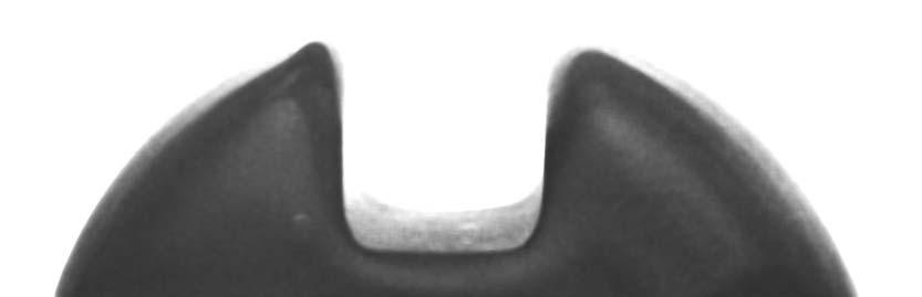
5 60 Hz CHARACTERISTICS The egg insulator is unique in the sense that it is the only do it yourself type you can buy. The behaviour of the insulator is influenced by the attachments made to it. The manufacturer of the egg, beyond controlling the quality of the piece of ceramic he supplies, has no control over the behaviour of the insulation system. Egg insulators differ in minor respects depending on the manufacturer, but they are all basically similar. Figures 1 and 2 show differing styles of insulators in common use. Figure 1 is typical of British manufacture and Figure 2, U.S.A. and Canada. Figure 3 shows the electrical characteristics of several types of eggs. The first three on the list are the most interesting because they are virtually identical and commonly used in Canada. Decades ago, this type was made to a U.S. Navy Specification and we believe several companies still produce them. It is significant to note that Locke, one of the original manufacturers of this style insulator, specifically did not recommend its use as primary insulation at radio frequencies. The last two insulators mentioned in the Table are somewhat larger units than the three referred to above. Tests were made several years ago in the U.S.A. on somewhat larger eggs than those mentioned above. (Reference 2). The tests were made at 60 Hz though the investigation was concerned with the application of these insulators at radio frequency. Figure 4 summarizes the results of these dry and wet tests. You will notice that the wet flashover is about half the dry flashover for one or two units in a string, but there is an improvement in the wet flash over with four units. A general conclusion would be that the wet flashover of a string of insulators is about fifty - 2 -
6 to seventy per cent of the dry flashover, and the effect of wet conditions is to even out the voltage gradient along the string. The report states that little improvement in flashover capability is achieved by putting more than four insulators in a string. It will be noted in Figure 4 that one wet test was carried out with the insulator inclined to the vertical. The flashover voltage was higher and attributed to the fact that when the string was vertical, drip water fell from the bottom of the upper cable loop down onto the lower cable. The tests made with the contaminated insulators show a lowered flashover voltage. This gives some indication of the performance if the system is located in a polluted area or near a salt water coast. The corona inception voltage of 14 KV on one dry insulator is low compared with the flashover voltage. The onset of corona is the beginning of an electrical discharge which will become visible and may turn into an arc. The low corona onset is a warning that operating voltages on egg insulators must be kept low in relation to flashover rating
7 FAILURE MODES Before discussing Radio Frequency tests it would be appropriate to examine some general characteristics of insulator materials when subjected to high voltage stress. An egg insulator behaves as the dielectric of a capacitor, the metallic guy loops being the plates. The principles of dielectric engineering apply. (Reference 3) There is no clear line of demarcation between an insulator and a conductor, and there is a third classification, the semi conductor. One broad distinction between these classifications is the volume resistivity and surface resistivity. The point when you cease to call a material an insulator and classify it as a semi conductor or a conductor is arguable. A further important distinction concerning the behaviour of an insulator and of a conductor is that, generally speaking, the resistance of a conductor increases with temperature whereas the resistance of an insulator decreases with the temperature. This is an important characteristic because the lowering of resistance with increasing temperature of an insulator tends to enhance electrical breakdown phenomena. When considering electrical grade porcelain, we are firmly in the realm of insulators. In the practical case of an egg insulator subjected to voltages normally encountered in a broadcast antenna system, the resistivity of porcelain is extremely high and the conduction current can be ignored. Surface leakage may become a problem if the surface becomes contaminated, but this is not due to any electrical property of the porcelain
8 Porcelain has a very high dielectric strength averaging 200 to 300 volts per mil for thin sections. The dielectric strength decreases somewhat as sections become thicker, but in any practical egg insulator there is sufficient thickness to guarantee that the insulator will not fail by puncturing simply due to inadequate dielectric strength. At the power frequency of 60 Hz (50 Hz), and considering the insulator as a capacitor, the charging current is small, due to the small capacity and high capacitive reactance. The amount of power lost in the dielectric is relatively small and heating effects are not usually a problem. As the frequency is raised, the current increases in proportion to the change in frequency. The amount of heat generated in the dielectric also increases. As we move into the lower radio frequencies, heating becomes a more serious consideration since we are now dealing with several hundred KHz. In the MF broadcast band, at 600 KHz, we have increased the frequency, and hence the current, ten thousand times. It is important to have a clear understanding of this particular cause of heating. We are not considering an I 2 R loss due to current flow through a resistance. The resistance of the porcelain is extremely high and the true conduction current extremely low. Dielectric heating, i.e. the rather complicated interaction of the molecules of the material with the electrical field is the main consideration. Not all the energy stored in the capacitor during each half cycle is recovered. The energy lost heats the dielectric. Usually when quoting the loss factor of an insulator, it is this loss that is being referred to. A more complete explanation is beyond the scope of - 5 -
9 this paper but there are many practical references on dielectric engineering. Dielectric heating, in raising the temperature of the ceramic, increases the insulator s vulnerability to thermal shock and resultant mechanical failure, and it also reduces the dielectric strength by increasing the mobility of the charge carriers. We seldom experience failure due solely to the heating effect in the dielectric unless it results in an excessive mechanical stress. What then is the principal cause of trouble? There is one failure mode which is likely to be predominant in any instance of egg insulator failure in a broadcast antenna system. The interface between a conductor and a dielectric material, in this case the wire loop around the insulator, is a critical area. With the egg insulator under a compressive load between the loops, the wire is making intimate contact with some portion of the porcelain, but there is an adjoining area near the point of contact where there is a highly stressed region or air. Figure 5 illustrates this. As soon as this air is over stressed, ionization occurs, a small arc develops, and highly destructive ozone and heat are produced. The insulator surface, at the point where the arc occurs, becomes very hot, and if the arc is allowed to continue, the glaze may melt and the insulator surface erode. A more likely occurrence is for the ceramic to crack quickly due to mechanical stress resulting from the heat of the arc. The arc will then work its way through the crack since air will enter and readily break down. The process continues until the insulator falls apart. It must be emphasized that one can only speak in general terms unless one is discussing a specific instance of failure. The variations in the possible sequence of events is almost limitless, but some photographs (Slides 1 8) will help to visualize the usual failure mechanism
10 We have heard that failures are less likely to occur if Preformed loops are used rather than wrapping the guy cable around the egg. We have also been told that it is good practice to put a lead sheath between the cable and the insulator. A number of our informants imply that these techniques reduce the possibility of failure due to mechanical loading. We think, rather, that the effect is to reduce the likelihood of arcs forming and that any failures which may otherwise have occurred would have resulted from thermal stress as a result of arcing
11 RADIO FREQUENCY TESTS We selected an Austin AOA 20 for testing. This insulator is stated by the manufacturer to have a 16 KV dry 60 Hz flashover and a wet flashover of 8 KV. In our literature we quote the 8 KV wet flashover rating and recommend a maximum radio frequency working voltage of 1.5 KV RMS. Slide 1. This shows a portion of our radio frequency test assembly. It is simply an oscillator (partly hidden to the left of the slide) with a power output capability up to 5 KW and a peak radio frequency voltage output up to 120 KV. Testing can be carried out in the MF range with this equipment. To the right can be seen an insulated frame in which we have suspended under tension a string of 3 egg insulators. It is important when carrying out tests of this nature that the insulators are under at least a few hundred pounds compressive load in the guy loops to ensure good contact between the conductors and the ceramic. Slide 2. We first investigated the behaviour of one insulator under dry conditions. A few patches of blue discharge appeared at 8.5 KV as the voltage was being raised. This visible discharge was similar to that which will be seen on Slide 5. As the voltage was raised further, the blue discharge became intense at 10 KV and after a few seconds an arc occurred which was initially over the surface of the porcelain at the top and between the wire loops. This is shown in Slide 2. Slide 3. After a minute or so a crack developed in the porcelain and the - 8 -
12 appearance of the arc changed from that shown in Slide 2. It will be noted in Slide 3 that the arc is not continuous over the top of the porcelain but is, in fact, passing through a crack. Though voltages of 8-10 KV were involved in the initiation of the arc, once the arc was formed the voltage across the insulator dropped to about 3 KV and required a further reduction to extinguish it. After a few minutes of operation with the arc present, the glaze melted under the arc and when the power was shut off the ceramic was white hot in the area where the arc occurred. Slide 4. This shows the insulator and the broken chip. We then carried out wet tests. The water used was of much greater conductivity than used in standard wet tests and we did not attempt to simulate standard 60 Hz wet test conditions but merely used a hose to spray the insulator. Slides 5 and 6. With the insulator wet a visible discharge started at 7 KV. The discharge was at the bottom of the insulator, probably due to the concentration of water at that point. (Slide 5 has been inadvertently printed upside down). Slide 7. This slide shows the effect of further wetting and an increase in voltage to 8 KV. There is more evidence of visible discharge and an arc has formed
13 Slide 8. This test is of 3 eggs of the same type in a string with 18 KV across the string. The top insulator has arced over. The second insulator has arced over and there is also some partial discharge. The bottom insulator has not arced but there is some discharge, only visible as a small blue dot on the slide. The uneven voltage distribution across the string is apparent. In this case the uneven distribution results from having the lower end of the string only a short distance above a large diameter metal ground plane
14 RADIO FREQUENCY TESTS (Continued) An investigation somewhat similar to ours was undertaken a few years ago by the Engineering Staff of the Canadian Broadcasting Corporation. (Reference 4). A frequency of 900 KHz was used and the behaviour of the egg insulator was reported as follows: As the voltage is increased a point is reached where a corona discharge occurs from the cable wrapped around the insulator, generally near the centre of the loop. This corona arc wanders around over a small area of the loop for a short period, about seconds, until it becomes concentrated in one spot and an arc to the porcelain is sustained. This arc is of very small diameter and shortly a spot will develop where the porcelain becomes white hot. After about two minutes of this the porcelain fractures. The insulators tested were similar to the unit we selected for our test. Four sizes were tested and the RMS voltage under dry conditions required to establish an arc averaged 8 KV. Once the arc was established, it required a reduction in voltage to about 3 KV before the arc extinguished. One of the conclusions stated in the C.B.C. report is that insulators of the type tested have a maximum safe operating voltage of 3 KV regardless of the size, this being based on the voltage at which an arc, once established, will extinguish. Though it is true that under dry conditions the tests we carried out and those carried out by the C.B.C. appear to establish 3 KV as being the arc extinction voltage for the insulators tested, there are many other factors to take into account. If an arc forms on the underside of some surface, it may be sustained at a lower voltage than if it is on an upper surface. An arc generates a lot of heat. If this heat is
15 trapped and cannot rise, it will be more difficult to gut the arc extinguished. If the hot gases are free to rise, this tends to lengthen the arc and increase the extinction voltage. An arc is more readily extinguished under windy conditions than in still air because the arc can be literally blown away. Any mechanism which tends to increase an arc path length also increases the extinction voltage. Though voltages of 8 to 12 KV were required on indoor dry tests to establish an arc across on insulator a higher or lower voltage may start an arc on an aerial system outdoors. The presence of dirt, sharp projections on the cable, rain, et cetera, may initiate an arc at a relatively low voltage. During our tests, we found that when we were getting a visible discharge which is the initial stage leading to an arc, it was only distinguishable at close range in a darkened room. This suggests that the chance of being able to observe this potentially dangerous situation on an antenna system by an observation made from the ground is practically zero. Even the small initial arcs which are incandescent gases and quite bright may still not be visible. It is only when the arc develops to a dangerous stage that it is likely to be visible from the ground. It is interesting to conjecture on the power loss when an insulator is arcing. We do have some initial data and we hope to make some measurements under sufficiently controlled conditions to be able to quote loss figures with authority at a later date. In the C.B.C. tests a 1 KW transmitter was used. Our test oscillator is a simple Hartley circuit and during the arc tests the power input to the transmitter was about 900 watts. We can assume we had about 500 to 600 watts available for an external load. The nature of our high voltage test circuit is such that it is inherently quite lossy and we estimate
16 that only 300 to 400 watts of power was actually expended in the test piece. The concentration of heat in the arc is terrific when one thinks of the power involved and the fact that we know the temperature reached something above 1000 C because it melted the glaze on the insulator. Porcelain does not conduct heat very well and it does not take kindly to mechanical stresses imposed by steep temperature gradients. It only takes a few minutes for the arc to crack the porcelain. Even if the insulator does not fall apart, the crack will be there. It will absorb moisture and from then on there will probably be electrical breakdowns
17 CONCLUSIONS This paper does not fully cover the subject of insulator failure. Any conclusions drawn should be more in the nature of guide lines than dogmatic statements. The following are a few of our thoughts: 1. Due to the geometry of an egg insulator and the common method of making attachments to it, the only way to reduce the hazard of an electrical failure is to keep the operating voltage at a low level, less than 5 KV per egg. Since in a long string it is likely that about forty per cent of the total voltage will appear across one insulator, this would limit the maximum operating voltage of any string of eggs to 12 KV. A safer figure for a string would be 7 KV based on a likely 3 KV maximum across the insulator carrying the highest stress. 2. The only advantage in increasing the number of eggs in a string beyond four is likely to result from an increase in surface leakage path which could be advantageous in wet weather or in a contaminated environment. 3. If an egg insulator appears to have broken in service, it is not safe to assume that it was faulty or over stressed mechanically. The failure may have occurred as a result of electrical stress. 4. If an egg is being replaced in the guy loops, examine the cable carefully for signs of pitting or other roughness. If this is not remedied the replacement insulator may also fail in a short time
18 5. Electrical failure of an egg insulator is not necessarily associated with high power. A few hundred watts is all that is needed. REFERENCES (1) W. W. Brown - Radio Frequency Tests on Antenna Insulators Proceedings of the Institute of Radio Engineers, Volume II, (2) General Electric Company - Unpublished report, High Voltage Laboratory (3) Dr. Andrew Blanck Principles of Dielectric Engineering, Electro Technology, June (4) J. K. MacDonald - Report No. 7:24:92, September 1967 C.B.C. Engineering Headquarters, Montreal


19 Figure 1 Figure 2
20

21
22


23


24
A-E01D1. Austin E-Cap Series Isolation Transformer
 Installation Instructions for A-E01D1 Austin E-Cap Series Isolation Transformer Dual Winding Multi-Voltage Revised Nov. 17, 2004 Austin Insulators Inc. 7510 Airport Road Mississauga, Ontario L4T 2H5, CANADA
CHAPTER 5 CONCEPT OF PD SIGNAL AND PRPD PATTERN
 75 CHAPTER 5 CONCEPT OF PD SIGNAL AND PRPD PATTERN 5.1 INTRODUCTION Partial Discharge (PD) detection is an important tool for monitoring insulation conditions in high voltage (HV) devices in power systems.
Evaluation of Distribution Line Spacers Located Near the Coast
 Evaluation of Distribution Line Spacers Located Near the Coast WALTER PINHEIRO ARNALDO G. KANASHIRO 2 GERALDO F. BURANI 2 Consultant Engineer University of São Paulo Av. Prof. Luciano Gualberto, 289, São
Evaluation of Distribution Line Spacers through the Leakage Current Monitoring
 Tsinghua University, Beijing, China, August -9, H-6 Evaluation of Distribution Line Spacers through the Leakage Current Monitoring A. G. Kanashiro *, W. Pinheiro and G. F. Burani Institute of Electrotechnics
Austin AUSTIN ISOLATION TRANSFORMER (DUAL WINDING SERIES) Installation Instructions for
 Installation Instructions for") Austin Installation Instructions for AUSTIN ISOLATION TRANSFORMER (DUAL WINDING SERIES) Austin Insulators Inc. 70 Airport Road Mississauga, Ontario LT H, CANADA tel: (90) 0-; fax: (90) 0-0 e-mail: support@austin-insulators.com
Austin Installation Instructions for AUSTIN ISOLATION TRANSFORMER (DUAL WINDING SERIES) Austin Insulators Inc. 70 Airport Road Mississauga, Ontario LT H, CANADA tel: (90) 0-; fax: (90) 0-0 e-mail: support@austin-insulators.com
IMPORTANCE OF INSULATION RESISTANCE
 IMPORTANCE OF INSULATION RESISTANCE What is Good Insulation? Every electric wire in your plant whether it s in a motor, generator, cable, switch, transformer, etc., is carefully covered with some form
High Frequency Voltage Stress. Presented by: Flore Chiang Date: March 30, 2012
 High Frequency Voltage Stress Presented by: Flore Chiang Date: March 30, 2012 Now the additional data is available! ground rules: 1. intro to PD. 2. experimental results. 3. comparison with current practice.
Porcelain Insulators & Covered Conductors A Problem of Dielectric Compatibility EDUARDO HILSDORF
 Porcelain Insulators & Covered Conductors A Problem of Dielectric Compatibility EDUARDO HILSDORF Porcelain Insulators and Covered Conductors A Problem of Dielectric Compa8bility Eduardo Riani Hilsdorf
A DUMMIES GUIDE TO GROUND FAULT PROTECTION
 A DUMMIES GUIDE TO GROUND FAULT PROTECTION A DUMMIES GUIDE TO GROUND FAULT PROTECTION What is Grounding? The term grounding is commonly used in the electrical industry to mean both equipment grounding
The Basics of Insulation Testing
 The Basics of Insulation Testing Feature by Jim Gregorec IDEAL Industries, Inc. What Is Insulation Testing? In a perfect world, all the electrical current sent along a conductive wire would reach its intended
What is Corona Effect in Power System and Why it Occurs?
 Corona Effect in Power System Electric power transmission practically deals in the bulk transfer of electrical energy, from generating stations situated many kilometers away from the main consumption centers
Analysis of Major Changes to Arrester Standards IEC STEVE BREWER
 Analysis of Major Changes to Arrester Standards IEC 60099-4 STEVE BREWER Analysis of Major Changes to Arrester Standard IEC 60099-4 Steve Brewer- Senior Product Manager - HPS Arrester Business Unit Agenda
Cisco Aironet 13.5-dBi Yagi Mast Mount Antenna (AIR-ANT1949)
") Cisco Aironet 13.5-dBi Yagi Mast Mount Antenna (AIR-ANT1949) Overview This document describes the 13.5-dBi Yagi mast mount antenna and provides instructions for mounting it. The antenna operates in the
Cisco Aironet 13.5-dBi Yagi Mast Mount Antenna (AIR-ANT1949) Overview This document describes the 13.5-dBi Yagi mast mount antenna and provides instructions for mounting it. The antenna operates in the
OPERATING AND MAINTENANCE MANUAL CORONAFINDER UV VIEWER
 A Division of www.syntronics.net OPERATING AND MAINTENANCE MANUAL CORONAFINDER UV VIEWER SYNTRONICS, LLC 3500 Shannon Park Drive Fredericksburg, VA 22408 USA Telephone and fax: (540) 374-1000 E-mail: nightvision@syntronics.net
The Reflective Wave Phenomena
 Application Note The Reflective Wave Phenomena Rev2.doc The Reflective Wave Phenomena Note to Specifiers This application note contains Cutler-Hammer s recommendations for the application of filters for
Insulator Testers Frequently Asked Questions. September Version: 1.1
 Insulator Testers Frequently Asked Questions September 2017 Version: 1.1 1 FAQ Contents Page Q1: When is it not safe to work on power lines?... 3 Q2: What is the tolerance of the Positron Insulator Tester
EE 1402 HIGH VOLTAGE ENGINEERING
 EE 1402 HIGH VOLTAGE ENGINEERING Unit 5 TESTS OF INSULATORS Type Test To Check The Design Features Routine Test To Check The Quality Of The Individual Test Piece. High Voltage Tests Include (i) Power frequency
ONLINE OFFLINE B Y WIL L IAM H IG INBOT H AM,
 ONLINE OFFLINE VERSUS FEATURE PARTIAL DISCHARGE TESTING FOR CABLE ASSESSMENT B Y WIL L IAM H IG INBOT H AM, EA Technology, LLC Medium voltage cables have three distinct phases to their lifecycle: (1) new
A CASE STUDY OF PARTIAL DISCHARGE AND ELECTRICAL TRACKING IN A 11KV METAL CLAD SWITCHGEAR
 A CASE STUDY OF PARTIAL DISCHARGE AND ELECTRICAL TRACKING IN A 11KV METAL CLAD SWITCHGEAR Anil Shrivastava Harsh Vardhana Kabra Abhijit Kumar HOD-Elect,NTPC SSTPS Dy.Manager,NTPC SSTPS Dy.Manager,NTPC
AMENDMENT NO. 1 SEPTEMBER IS (Part 1) : 2001/IEC (1991) SURGE ARRESTORS
 : 2001/IEC (1991) SURGE ARRESTORS") AMENDMENT NO. 1 SEPTEMBER 2011 TO IS 15086 (Part 1) : 2001/IEC 60099-1 (1991) SURGE ARRESTORS PART 1 NON-LINEAR RESISTOR TYPE GAPPED SURGE ARRESTORS FOR a.c. SYSTEMS (The Amendment was originally published
AMENDMENT NO. 1 SEPTEMBER 2011 TO IS 15086 (Part 1) : 2001/IEC 60099-1 (1991) SURGE ARRESTORS PART 1 NON-LINEAR RESISTOR TYPE GAPPED SURGE ARRESTORS FOR a.c. SYSTEMS (The Amendment was originally published
Defects in Nonceramic Insulators: Can They be Detected in a Timely Manner?
 Defects in Nonceramic Insulators: Can They be Detected in a Timely Manner? S. Gorur and S. Sivasubramaniyam Department of Electrical Engineering, Arizona State University, Tempe, AZ, USA This work was
Be on guard for effective testing: Introduction
 Be on guard for effective testing: Introduction The development of the insulation tester by Evershed and Vignoles is part of our electrical history, with insulation testers produced by Megger Instruments
Instructions For Installing A Pig Fence
 Instructions For Installing A Pig Fence A Multi-wire Fence on a Single Line of Posts Height: 18 Inches Polywire for seasonally removable fences Aluminum wire for permanent fences These pages provide the
The University of New South Wales. School of Electrical Engineering and Telecommunications. High Voltage Systems ELEC9712. Appendix Partial Discharge
 The University of New South Wales School of Electrical Engineering and Telecommunications High Voltage Systems ELEC9712 Appendix Partial Discharge Content Introduction Quantities measured Test circuits
FUNCTIONS OF CIRCUIT BREAKERS
 FUNCTIONS OF CIRCUIT BREAKERS Circuit breakers are designed to carry out the following functions: 1. They must be capable of closing on and carrying full-load currents at rated power factors continuously.
Extended analysis versus frequency of partial discharges phenomena, in support of quality assessment of insulating systems
 Extended analysis versus frequency of partial discharges phenomena, in support of quality assessment of insulating systems Romeo C. Ciobanu, Cristina Schreiner, Ramona Burlacu, Cristina Bratescu Technical
Cisco Aironet Omnidirectional Mast Mount Antenna (AIR-ANT2506)
") Cisco Aironet Omnidirectional Mast Mount Antenna (AIR-ANT2506) This document outlines the specifications, describes the omnidirectional mast mount antenna, and provides instructions for mounting it. Designed
Cisco Aironet Omnidirectional Mast Mount Antenna (AIR-ANT2506) This document outlines the specifications, describes the omnidirectional mast mount antenna, and provides instructions for mounting it. Designed
CHAPTER 10 HIGH VOLTAGE TESTING OF ELECTRICAL APPARATUS
 CHAPTER 10 HIGH VOLTAGE TESTING OF ELECTRICAL APPARATUS 1. Introduction 2. Classification of High Voltage Tests 3. Test Voltages 4. High Voltage Testing of Electrical Apparatus 1. INTRODUCTION Purpose
Industrial and Commercial Power Systems Topic 7 EARTHING
 The University of New South Wales School of Electrical Engineering and Telecommunications Industrial and Commercial Power Systems Topic 7 EARTHING 1 INTRODUCTION Advantages of earthing (grounding): Limitation
International Journal of Advance Engineering and Research Development. Comparison of Partial Discharge Detection Techniques of Transformer
 Scientific Journal of Impact Factor(SJIF): 3.134 International Journal of Advance Engineering and Research Development Volume 2,Issue 7, July -2015 e-issn(o): 2348-4470 p-issn(p): 2348-6406 Comparison
Prepared by Mick Maytum
 IEC Technical Committee 109: Standards on insulation co-ordination for low-voltage equipment Warning Prepared by Mick Maytum mjmaytum@gmail.com The document content is of a general nature only and is not
Circuit Breaker. By Shashidhar kasthala Assistant Professor Indian Naval Academy
 Circuit Breaker By Shashidhar kasthala Assistant Professor Indian Naval Academy In power system, various circuits (e.g., transmission lines, distributors, generating plants etc.) will be switch on-off
On-line Partial Discharge Assessment and Monitoring of MV to EHV Cables
 On-line Partial Discharge Assessment and Monitoring of MV to EHV Cables William Higinbotham, Neil Davies and Victor Chan EA Technology LLC, New Jersey; USA, EA Technology Pty Ltd, Brisbane Australia; EA
2 Grounding of power supply system neutral
 2 Grounding of power supply system neutral 2.1 Introduction As we had seen in the previous chapter, grounding of supply system neutral fulfills two important functions. 1. It provides a reference for the
Chapter 12: Transmission Lines. EET-223: RF Communication Circuits Walter Lara
 Chapter 12: Transmission Lines EET-223: RF Communication Circuits Walter Lara Introduction A transmission line can be defined as the conductive connections between system elements that carry signal power.
Radar Detection of Lightning. Williams et al. (1989, J. Atmos. Sci.)
") Radar Detection of Lightning Williams et al. (1989, J. Atmos. Sci.) Observations of lightning by radar has a history as long as radar itself. Generally accepted that radar echoes from lightning are reflections
Radar Detection of Lightning Williams et al. (1989, J. Atmos. Sci.) Observations of lightning by radar has a history as long as radar itself. Generally accepted that radar echoes from lightning are reflections
CHAPTER 2. Development of a PXI controller based data. acquisition system for on line remote monitoring. of leakage current on RTV coated insulators
 29 CHAPTER 2 Development of a PXI controller based data acquisition system for on line remote monitoring of leakage current on RTV coated insulators 2.0 Introduction The continuous operation of the transmission
MTE training MTE Corporation
 1 MTE Corporation Improving the Performance and Reliability of Power Electronic Systems 2 MTE solutions to Long lead dive applications Protection of motors drive cables and Variable frequency inverters
Manufacturing Process - I Dr. D. K. Dwivedi Department of Mechanical and Industrial Engineering Indian Institute of Technology, Roorkee
 Manufacturing Process - I Dr. D. K. Dwivedi Department of Mechanical and Industrial Engineering Indian Institute of Technology, Roorkee Module - 3 Lecture - 5 Arc Welding Power Source Part 2 Welcome students.
AMTS STANDARD WORKSHOP PRACTICE. Bond Design
 AMTS STANDARD WORKSHOP PRACTICE Reference Number: AMTS_SWP_0027_2008 Date: December 2008 Version: A 1 Contents 1 Technical Terms...3 2 Scope...3 3 Primary References...3 4 Basic...3 4.1 Typical joint types...4
Helically Loaded Magnetic Loop Antenna
 Helically Loaded Magnetic Loop Antenna Object of the design: There are many designs and information available on the net concerning Magnetic Loop Antennas. Even though these antennas are a fraction of
Electrical Severity Measurement Tool Revision 4
 Electrical Severity Measurement Tool Revision 4 November 2017 Electrical Severity Measurement Tool 1.0 Purpose: This tool is intended to measure the severity of exposure to an electrical safety event based
THE PROPAGATION OF PARTIAL DISCHARGE PULSES IN A HIGH VOLTAGE CABLE
 THE PROPAGATION OF PARTIAL DISCHARGE PULSES IN A HIGH VOLTAGE CABLE Z.Liu, B.T.Phung, T.R.Blackburn and R.E.James School of Electrical Engineering and Telecommuniications University of New South Wales
Technical Specifications - Characteristics
 Watt FM TRANSMITTER General Description This is a small but quite powerful FM transmitter having three RF stages incorporating an audio preamplifier for better modulation. t has an output power of 4 Watts
CoolBLUE Inductive Absorbers NaLA Noise Line Absorbers
 CoolBLUE Inductive Absorbers NaLA Noise Line Absorbers Motor Bearing Solution from MH&W International Corp. http://www.coolblue-mhw.com Variable Frequency Motor Drive Systems 1. What is the problem 2.
GSM Repeater Systems & Accessories
 GSM Repeater Systems & Accessories MOBILE SIGNAL BOOSTER Instruction Manual SKU: AG10(P) WR1800(P) WR2100(P) Mobile phone repeater system is designed to take and amplify existing mobile phone signal in
CONDUCTOR CORONA NOISE PREDICTION ON HIGH VOLTAGE AC LINES
 CONDUCTOR CORONA NOISE PREDICTION ON HIGH VOLTAGE AC LINES R.G. Urban*, H.C. Reader*, J.P. Holtzhausen*, K.R. Hubbard**, A.C. Britten** & D.C. Smith** * Department of EE Engineering, University of Stellenbosch,
Characteristics of Insulation Diagnosis and Failure in Gas Turbine Generator Stator Windings
 J Electr Eng Technol Vol. 9, No. 1: 280-285, 2014 http://dx.doi.org/10.5370/jeet.2014.9.1.280 ISSN(Print) 1975-0102 ISSN(Online) 2093-7423 Characteristics of Insulation Diagnosis and Failure in Gas Turbine
CONTENTS. 1. Introduction Generating Stations 9 40
 CONTENTS 1. Introduction 1 8 Importance of Electrical Energy Generation of Electrical Energy Sources of Energy Comparison of Energy Sources Units of Energy Relationship among Energy Units Efficiency Calorific
PAGE 12 : THREAD MEASUREMENT TECHNIQUE (Plated and unplated thread gauges)
") 40-60 Delaware St. MACHINING Part No. PR301 - INDEX- MACHINING SECTION Revision: 01/12/2012 PAGE 1 This Quality Standard applies to all metallic parts unless otherwise specified by drawing or specification.
40-60 Delaware St. MACHINING Part No. PR301 - INDEX- MACHINING SECTION Revision: 01/12/2012 PAGE 1 This Quality Standard applies to all metallic parts unless otherwise specified by drawing or specification.
ANSI DESIGN TEST REPORT Report No. EU1295-H-00 Type PVN Station Class Surge Arrester
 ANSI DESIGN TEST REPORT Report No. EU1295-H-00 Type PVN Station Class Surge Arrester This report records the results of the design tests made on Type PVN Station Class surge arresters in accordance with
Cisco Aironet 2.4-GHz/5-GHz 8-dBi Directional Antenna (AIR-ANT2588P3M-N)
") Cisco Aironet.4-GHz/5-GHz 8-dBi Directional Antenna (AIR-ANT588P3M-N) This document outlines the specifications for the Cisco Aironet AIR-ANT588P3M-N.4/5-GHz 8-dBi 3-Port Directional Antenna with N-connectors
Cisco Aironet.4-GHz/5-GHz 8-dBi Directional Antenna (AIR-ANT588P3M-N) This document outlines the specifications for the Cisco Aironet AIR-ANT588P3M-N.4/5-GHz 8-dBi 3-Port Directional Antenna with N-connectors
HARMONICS CAUSES AND EFFECTS
 HARMONICS CAUSES AND EFFECTS What is Harmonics? Harmonics is defined as the content of the signal whose frequency is an integral multiple of the system frequency of the fundamentals. Harmonics current
A controlled arc-flash, produced in a flashtube. Even though the energy level used is fairly low (85 joules), the low-impedance, low-inductance
, the low-impedance, low-inductance") An arc flash (also called a flashover), which is distinctly different from the arc blast, is part of an arc fault, a type of electrical explosion or discharge that results from a low-impedance connection
An arc flash (also called a flashover), which is distinctly different from the arc blast, is part of an arc fault, a type of electrical explosion or discharge that results from a low-impedance connection
Testing 320 kv HVDC XLPE Cable System
 Testing 320 kv HVDC XLPE Cable System H. He, W. Sloot DNV GL, KEMA Laboratories Arnhem, The Netherlands Abstract Two unique test requirements in testing of a high- voltage direct- current (HVDC) cable
Use optocouplers for safe and reliable electrical systems
 1 di 5 04/01/2013 10.15 Use optocouplers for safe and reliable electrical systems Harold Tisbe, Avago Technologies Inc. 1/2/2013 9:06 AM EST Although there are multiple technologies--capacitive, magnetic,
Introduction. AC or DC? Insulation Current Flow (AC) 1. TECHNICAL BULLETIN 012a Principles of Insulation Testing. Page 1 of 10 January 9, 2002
 1. TECHNICAL BULLETIN 012a Principles of Insulation Testing. Page 1 of 10 January 9, 2002") Page 1 of 10 January 9, 2002 TECHNICAL BULLETIN 012a Principles of Insulation Testing Introduction Probably 80% of all testing performed in electrical power systems is related to the verification of insulation
Page 1 of 10 January 9, 2002 TECHNICAL BULLETIN 012a Principles of Insulation Testing Introduction Probably 80% of all testing performed in electrical power systems is related to the verification of insulation
UNIT 4 PRINCIPLES OF CIRCUIT BREAKERS SVCET
 UNIT 4 PRINCIPLES OF CIRCUIT BREAKERS Introduction Where fuses are unsuitable or inadequate, protective relays and circuit breakers are used in combination to detect and isolate faults. Circuit breakers
DEPARTMENT OF DEFENSE TEST METHOD STANDARD METHOD 301, DIELECTRIC WITHSTANDING VOLTAGE
 INCH-POUND MIL-STD-202-301 18 April 2015 SUPERSEDING MIL-STD-202G w/change 2 (IN PART) 28 June 2013 (see 6.1) DEPARTMENT OF DEFENSE TEST METHOD STANDARD METHOD 301, DIELECTRIC WITHSTANDING VOLTAGE AMSC
Radar. Radio. Electronics. Television. .104f 4E011 UNITED ELECTRONICS LABORATORIES LOUISVILLE
 Electronics Radio Television.104f Radar UNITED ELECTRONICS LABORATORIES LOUISVILLE KENTUCKY REVISED 1967 4E011 1:1111E111611 COPYRIGHT 1956 UNITED ELECTRONICS LABORATORIES POWER SUPPLIES ASSIGNMENT 23
Investigation on Leakage Current Waveforms and Flashover Characteristics of Ceramics for Outdoor Insulators under Clean and Salt Fogs
 Investigation on Leakage Current Waveforms and Flashover Characteristics of Ceramics for Outdoor Insulators under Clean and Salt Fogs Suwarno Juniko P School of Electrical Engineering and Informatics Bandung
TECHNICAL SPECIFICATION
 TECHNICAL SPECIFICATION 1. SCOPE : TECHNICAL SPECIFICATION FOR LIGHTNING ARRESTORS 1.1. This Specification covers design, manufacture, testing at manufacturer's Works, packing, supply, delivery of 42 KV
Partial Discharge Classification Using Acoustic Signals and Artificial Neural Networks
 Proc. 2018 Electrostatics Joint Conference 1 Partial Discharge Classification Using Acoustic Signals and Artificial Neural Networks Satish Kumar Polisetty, Shesha Jayaram and Ayman El-Hag Department of
RlGIDITY AND STRENGTH OF WALL FRAMES BRACED WlTH METAL STRAPPING
 RlGIDITY AND STRENGTH OF WALL FRAMES BRACED WlTH METAL STRAPPING information Reviewed and Reaffirmed March 1955 No. R1603 UNITED STATES DEPARTMENT OF AGRICULTURE FOREST SERVICE FOREST PRODUCTS LABORATORY
INSTRUMENTATION FOR LONG TERM CONTINUOUS MEASUREMENT OF GROUND LEVEL ATMOSPHERIC ELECTRIC FIELDS
 INSTRUMENTATION FOR LONG TERM CONTINUOUS MEASUREMENT OF GROUND LEVEL ATMOSPHERIC ELECTRIC FIELDS John Chubb Infostatic Ltd, 2 Monica Drive, Pittville, Cheltenham, GL50 4NQ, UK email: jchubb@infostatic.co.uk
NEW MV CABLE ACCESSORY WITH EMBEDDED SENSOR TO CHECK PARTIAL DISCHARGE ACTIVITY
 NEW MV CABLE ACCESSORY WITH EMBEDDED SENSOR TO CHECK PARTIAL DISCHARGE ACTIVITY Lorenzo PERETTO Luigi FODDAI Simone ORRU Luigi PUDDU Altea Switzerland ENEL Italy ENEL Italy REPL Italy lperetto@alteasolutions.com
DIELECTRIC HEATING IN INSULATING MATERIALS AT HIGH DC AND AC VOLTAGES SUPERIMPOSED BY HIGH FREQUENCY HIGH VOLTAGES
 DIELECTRIC HEATING IN INSULATING MATERIALS AT HIGH DC AND AC VOLTAGES SUPERIMPOSED BY HIGH FREQUENCY HIGH VOLTAGES Matthias Birle * and Carsten Leu Ilmenau University of technology, Centre for electrical
Sessile Water Droplets on Insulating Surfaces Subject to High AC Stress: Effect of Contact Angle.
 Sessile Water Droplets on Insulating Surfaces Subject to High AC Stress: Effect of Contact Angle. H. A. Gouda, B. H. Crichton, R. A. Fouracre and M. Stickland* Applied Electrical Technology Group, Institute
!DETECTION OF COMPRESSION FAILURES IN WOOD
 AGRICULTURE ROOM!DETECTION OF COMPRESSION FAILURES IN WOOD Information Reviewed and Reaffirmed May 1961 No. 1388 FOREST PRODUCTS LABORATORY MADISON 5, WISCONSIN UNITED STATES DEPARTMENT OF AGRICULTURE
CHAPTER 2. v-t CHARACTERISTICS FOR STANDARD IMPULSE VOLTAGES
 23 CHAPTER 2 v-t CHARACTERISTICS FOR STANDARD IMPULSE VOLTAGES 2.1 INTRODUCTION For reliable design of power system, proper insulation coordination among the power system equipment is necessary. Insulation
WIRELESS INSULATOR POLLUTION MONITORING SYSTEM
 SYSTEM OVERVIEW Pollution monitoring of high voltage insulators in electrical power transmission and distribution systems, switchyards and substations is essential in order to minimise the risk of power
شركة الوقت للكهرباء والمقاوالت ذ.م.م.
 CONTRACTING COMPANY W.L.L. is a leading corporate in the United Arab Emirates offering quality services in the field of High Voltage Electrical work 400, 132 & 33 kv and Medium Voltage Power Distribution
CAPACITORS. Capacitors for AC and DC General Purpose Applications. Proven EIA-456-A Compliant 60,000 Hour Reliability Industry Standard
 CAPACITORS Capacitors for AC and DC General Purpose Applications Proven EIA-456-A Compliant 60,000 Hour Reliability Industry Standard To ensure correct selection of a capacitor for your application, please
TECHNICAL BULLETIN 004a Ferroresonance
 May 29, 2002 TECHNICAL BULLETIN 004a Ferroresonance Abstract - This paper describes the phenomenon of ferroresonance, the conditions under which it may appear in electric power systems, and some techniques
MAHALAKSHMI ENGINEERING COLLEGE
 MAHALAKSHMI ENGINEERING COLLEGE TIRUCHIRAPALLI 621213 QUESTION BANK -------------------------------------------------------------------------------------------------------------- Sub. Code : EE2353 Semester
Using High Tensile Wire
 Fencing Systems for Rotational Grazing Using High Tensile Wire Using High Tensile Wire Tom Cadwallader and Dennis Cosgrove University of Wisconsin-Extension 1 Installing the High Tensile Wires There are
2013 Applied Power Electronics Conference (APEC) Page 1 of 8
 Page 1 of 8") This presentation describes AC capacitors that are manufactured with film with aluminum foil, dielectric technology and applied in medium voltage systems. We are defining these medium voltage systems as
This presentation describes AC capacitors that are manufactured with film with aluminum foil, dielectric technology and applied in medium voltage systems. We are defining these medium voltage systems as
All the standards referred to the most current issue, including all amendment supplements. as of the date of the bid.
 1. Scope This specification defines the methods, the procedures and the requirements to verify the cables manufactured according to I.E.C. Specifications NPS361. 2. Standards All the standards referred
PD Diagnostic Applications and TechImp solutions
 PD Diagnostic Applications and TechImp solutions Condition Assessment Solutions for Electrical Systems. PD based innovative tools for the Condition Based Maintenance. MD-04.05.004 - rev. 00-29/08/2006
Partial Discharge Patterns in High Voltage Insulation
 22 IEEE International Conference on Power and Energy (PECon), 2-5 December 22, Kota Kinabalu Sabah, Malaysia Partial Discharge Patterns in High Voltage Insulation Hazlee Illias, Teo Soon Yuan, Ab Halim
PCB Design Guidelines for GPS chipset designs. Section 1. Section 2. Section 3. Section 4. Section 5
 PCB Design Guidelines for GPS chipset designs The main sections of this white paper are laid out follows: Section 1 Introduction Section 2 RF Design Issues Section 3 Sirf Receiver layout guidelines Section
HARMONIC ANALYSIS OF LEAKAGE CURRENT OF SILICON RUBBER INSULATORS IN CLEAN-FOG AND SALT-FOG
 HARMONIC ANALYSIS OF LEAKAGE CURRENT OF SILICON RUBBER INSULATORS IN CLEAN-FOG AND SALT-FOG Mojtaba Rostaghi-Chalaki, A Shayegani-Akmal, H Mohseni To cite this version: Mojtaba Rostaghi-Chalaki, A Shayegani-Akmal,
Cisco Aironet Dual-Band MIMO Wall-Mounted Omnidirectional Antenna (AIR-ANT2544V4M-R)
") Cisco Aironet Dual-Band MIMO Wall-Mounted Omnidirectional Antenna (AIR-ANT2544V4M-R) This document outlines the specifications for the Cisco Aironet 2.4-GHz/5-GHz Dual-Band MIMO Wall-Mounted Omnidirectional
Cisco Aironet Dual-Band MIMO Wall-Mounted Omnidirectional Antenna (AIR-ANT2544V4M-R) This document outlines the specifications for the Cisco Aironet 2.4-GHz/5-GHz Dual-Band MIMO Wall-Mounted Omnidirectional
ROEVER ENGINEERING COLLEGE ELAMBALUR, PERAMBALUR DEPARTMENT OF ELECTRICAL & ELECTRONICS ENGINEERING
 ROEVER ENGINEERING COLLEGE ELAMBALUR, PERAMBALUR 621 212 DEPARTMENT OF ELECTRICAL & ELECTRONICS ENGINEERING EE1003 HIGH VOLTAGE ENGINEERING QUESTION BANK UNIT-I OVER VOLTAGES IN ELECTRICAL POWER SYSTEM
INTRODUCTION: The following paper is intended to inform on the subject at hand and is based on years of laboratory observations.
 INTRODUCTION: The following paper is intended to inform on the subject at hand and is based on years of laboratory observations. Fretting motion, fretting wear, fretting corrosion what does it all mean
USER MANUAL MG-TA1000 POWER AMPLIFIER
 USER MANUAL MG-TA1000 POWER AMPLIFIER INDEX: INTRODUCTION SAFETY INSTRUCTIONS OPERATING PRECAUTIONS FEATURES OF PANAL CONTROLS FRONT & REAR PPANEL DISPLAY CONNECTING INPUTS SPEAKER CONNECTIONS INTRODUCTION:
User Guide for the Alpha Loop Sr Antenna
 User Guide for the Alpha Loop Sr Antenna Manufactured by: Alpha Antenna 1.888.482.3249 Website: http://alphaantenna.com Available from: Amateur Radio Store Website: https://amateurradiostore.com User Guide
Application Note. About VFD Cables Steve Wetzel, Sr. Product Engineer
 Application Note About VFD Cables Steve Wetzel, Sr. Product Engineer A variable-frequency drive (VFD) cable is a special cable construction for the inverter-to-motor cable that has some or all of the following
AC Voltage- Pipeline Safety and Corrosion MEA 2015
 AC Voltage- Pipeline Safety and Corrosion MEA 2015 WHAT ARE THE CONCERNS ASSOCIATED WITH AC VOLTAGES ON PIPELINES? AC concerns Induced AC Faults Lightning Capacitive coupling Safety Code Induced AC Corrosion
Ramp Testing in Identifying and Preventing Insulation Failure
 FEATURE Megger Ramp Testing in Identifying and Preventing Insulation Failure By Jeff Jowett THE TESTING OF ELECTRICAL INSULATION has Simply taking a spot resistance reading with a megohmmeter seen the
MARTINDALE INSTRUCTIONS. E-ZeTest EZ2500 LOOP TESTER ELECTRIC. Trusted by professionals. Other products from Martindale:
 Other products from Martindale: 17th Edition Testers All-in-one s Calibration Equipment Continuity Testers Electrician s kits Full Calibration & Repair Service Fuse Finders Digital Clamp Meters Digital
Application Note. Soldering Guidelines for Surface Mount Filters. 1. Introduction. 2. General
 Soldering Guidelines for Surface Mount Filters 1. Introduction This Application Guideline is intended to provide general recommendations for handling, mounting and soldering of Surface Mount Filters. These
Innovative Test Techniques and Diagnostic Measurements to Improve the Performance and Reliability of Power System Transformers
 Innovative Test Techniques and Diagnostic Measurements to Improve the Performance and Reliability of Power System Transformers Dr. Michael Krüger, Alexander Kraetge, OMICRON electronics GmbH, Austria Alexander
INDEX OPERATING PRINCIPLE... 3 Power Supply... 4 Replacing the Batteries... 4 GENERAL PHOTOMETER OPERATION... 4 Operating Modes... 4 SYSTEM MODE...
 9300 PHOTOMETER The YSI 9300 direct-reading photometer is designed to give long and troublefree operation. To ensure the best results, please read these instructions carefully and follow the procedures
what is a multiplier? how does a multiplier work? common multiplier applications II. Assembly Type III. Other Design Concerns
 SECTION 13 Multipliers VMI manufactures many high voltage multipliers, most of which are custom designed for specific requirements. The following information provides general information and basic guidance
PHASE ROTATION METER. Operating and Instruction Manual. a n d A C C E S S O R I E S
 PHASE ROTATION METER a n d A C C E S S O R I E S Operating and Instruction Manual HD ELECTRIC COMPANY 1 4 7 5 L A K E S I D E D R I V E WA U K E G A N, I L L I N O I S 6 0 0 8 5 U. S. A. PHONE 847.473.4980
5. The Different Types of Resistors
 5. The Different Types of Resistors Resistors ( R ), are the most fundamental and commonly used of all the electronic components, to the point where they are almost taken for granted. There are many different
COURSE: ADVANCED MANUFACTURING PROCESSES. Module No. 5: OTHER PROCESSES
 COURSE: ADVANCED MANUFACTURING PROCESSES Module No. 5: OTHER PROCESSES Lecture No-3 Microwave Processing of Materials Microwave processing is a relatively new and emerging area in material processing.
Technical Information
 Technical Information Introduction to force sensors Driving long cable lengths Conversions, article reprints, glossary INTRODUCTION TO QUARTZ FORCE SENSORS Quartz Force Sensors are well suited for dynamic
FGJTCFWP"KPUVKVWVG"QH"VGEJPQNQI[" FGRCTVOGPV"QH"GNGEVTKECN"GPIKPGGTKPI" VGG"246"JKIJ"XQNVCIG"GPIKPGGTKPI
 FGJTFWP"KPUKWG"QH"GEJPQNQI[" FGRTOGP"QH"GNGETKEN"GPIKPGGTKPI" GG"46"JKIJ"XQNIG"GPIKPGGTKPI Resonant Transformers: The fig. (b) shows the equivalent circuit of a high voltage testing transformer (shown