Helically Loaded Magnetic Loop Antenna
|
|
|
- Beatrix McLaughlin
- 6 years ago
- Views:
Transcription

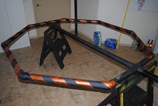
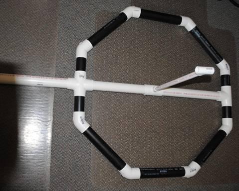
1 Helically Loaded Magnetic Loop Antenna Object of the design: There are many designs and information available on the net concerning Magnetic Loop Antennas. Even though these antennas are a fraction of the size of a full size resonant antenna, size of the lower frequency loop can still be quite large for a limited sized property. The object of my design is to compact the size of a magnetic loop while trying to maintain the efficiency of the loop. Theory of Design: Anyone that has delved into the theory of magnetic loops knows that smaller size loops result in very poor efficiency at lower frequencies. A magnetic loop for the 80 meter band should be 15 ft diameter to produce efficiency of 88%. Using a 3 diameter copper pipe at a 15 ft diameter will only produce a 7Khz band width. This band width requires very precise tuning. By implementing a helically wound design a 6ft diameter 80 meter text book loop seems to emulate a 10 to 15 ft diameter loop of a single conductor. The 80 meter bandwidth of my 6 ft loop is 11Khz. The loop construction technique provides for light weight and cost as compared to a 15 ft loop constructed from copper tubing. This (1 of 18)9/11/ :24:38
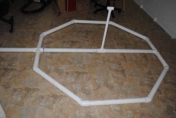
2 design has been accomplished by using just enough copper to take advantage of Skin Effect. This allows the use of a thin flat copper conductor which provides more surface area then a heavy copper pipe while still providing a large surface area of RF skin depth. At the same time the radiation resistance is raised considerably while only raising the IR losses slightly. The ratio of Radiation Resistance to IR losses equals the efficiency. The use of PVC tubing and flat soft copper strap provides a sturdy substrate in which to wrap the soft copper strap while increasing inductance for the same circumference as a substantially larger loop. The result is a two part gain; the same length of copper conductor that is required for a 10 ft diameter loop equates to similar performance wound on a 6 ft diameter substrate; thus reducing the size, weight and cost while still retaining the performance. These miniature loops for bands as low as 80 meters have now become such a small footprint that they can be employed in an HOA situation even if hidden between foliage. There are still a few factors that I have not calculated yet. The use of loading and the distributed capacitance somewhat adds a mysterious factor to this design. I am still working out all the details. The apparent efficiency and the large increase in Band Width tell the story. My actual on the air testing has depicted better results than I could have imagined. So far my seat of the pants measurements has shown a great increase in the tightness of the doughnut pattern shape. The approximate 4 degree very sharp null I am seeing to near E field noise seems much tighter then my previous single conductor loops. I have also noticed from many signal reports that I am experiencing as much as 3 to 4 S-units increase/ decrease in signal strength by rotating the antenna with distant stations. This seems to be more apparent depending on the angle of radiation being utilized at the time of contact. There may possibly be more horizontal radiation off the side then a normal single conductor loop; this is just theory for explanation at this point. The reason that I am theorizing the polarization is due to the fact that I have seen stations get much stronger broadside while I other stations get much stronger in the plane of the loop. Text book magnetic loop theory states stronger in the plane of the loop. This is definitely the case for ground wave stations; I have tested this in depth with great repeatability. I can get a 3 to 4 S unit change at 20 miles on the 20 meter band, the signal will just about completely null broadside to the loop. Details of building this design: The Hi-Res photos that I am attaching to this article will depict more than can be described, thus I will not go into great detail. Starting with the PVC octagon frame, calculate your PVC parts by the size of the loop desired for the particular frequency range. View my photos carefully to observe how to mount the SO-239 connector; do this before gluing any frame parts. (2 of 18)9/11/ :24:38


3 Use a hard temper piece of copper flashing for the underlay of the SO-239 connector. Soldering this connector as the photo shows is important. The photo also depicts how the center feed from the SO-239 was routed thru the PVC- T. Finish this part carefully before any gluing. Use a short length of ¼ inch copper tubing to follow thru the PVC T for stability of the connection. If this connection breaks after gluing the frame you will be in trouble! Fill the short length of tubing with solder then heat it a push it over the center conductor of the SO-239 and heat generously. The other exiting end out of the PVC T will then be supported by the T itself, this makes for a very strong connection point. Use cleaner and good glue and glue the frame together, use ingenuity when assembling the frame as to what parts to glue first. Once the part is glued and it isn t (3 of 18)9/11/ :24:38


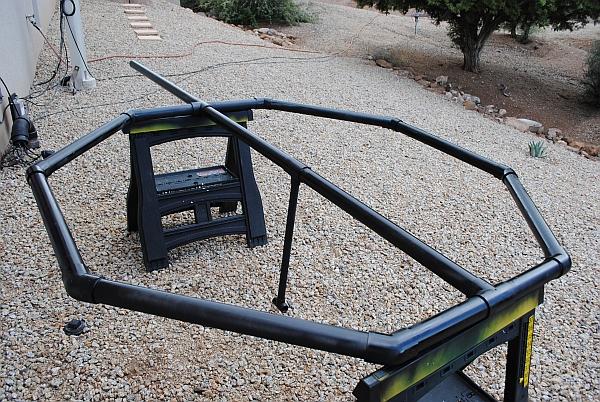
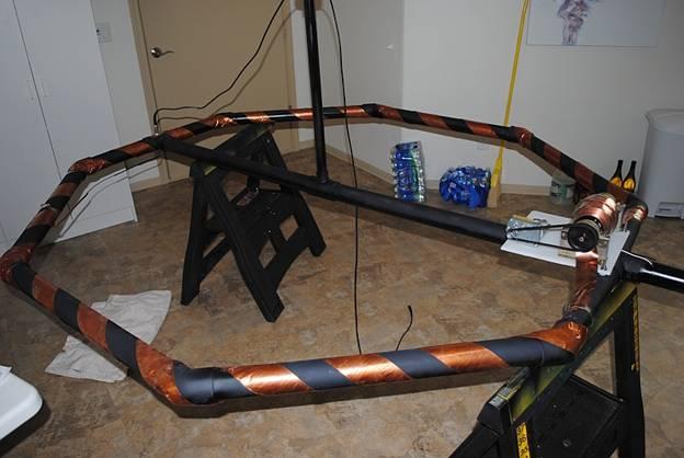
4 right it will be very difficult to correct. Make sure to use both good quality PVC cleaner and Cement for good bond which will provide stability of the frame. The frame will need about 3 coats of high quality Krylon spray paint. I use flat black as it hides well, Krylon makes a spray paint for plastics; this is the one that I recommend. If you do not paint the frame the PVC will deteriorate fast especially in the western state where I am located. The next generation of prototype will use a plastic protective paint on the substrate and a clear lacquer coating over the copper for corrosive protection. Now it s time to wrap the frame, this part is a bit tricky the first time you do it. The rule that used to build both prototype loops was adding 37.5 % of conductor length to the amount of conductor required for a single turn loop. Credit is given here to AA5TB the work on a great loop calculator. AA5TB calculator has been very useful to speed up calculations, I have compared it to hand calculations, it is very exact; just search the net for his Excel program. Plug in all the factors for the loop that you want to build and follow my rule for length of conductor. Use the width of the copper strap X2 in place of the circumference (diameter X 3.14) the formula requires diameter. Divide the calculated length of the conductor in half, and mark the center of the length. Start the wrapping at the marked center at the SO-239, pay close attention to the pitch of the material. Again some ingenuity on calculating the wrap spacing is necessary here. Make sure that the two ends of the material come out even at the capacitor/tuner feed point. If care is not taken here you will have an unbalanced loop. Once the loop is wrapped and if it came out even, then temporarily tape the ends in place while you solder the center of the flashing very carefully to the so-239 supporting foil. Capacitor & Drive Motor Assy: (4 of 18)9/11/ :24:38

5 The tuning capacitor is one of the most critical devices in this build project. Choosing to use anything but a good quality vacuum variable capacitor will result in substandard performance compared to the results claimed in this prototype antenna. First issue is power handling, my loops handle SSB full legal limit (1500wts), and are rarely run at more than 1Kw. To keep the Q high and power capability high use a vacuum cap otherwise the results will probably be disappointing. Humidity will also play a role in affecting your antenna by using an air capacitor. I am using a 12 volt gear reduction motor with a forward and reverse controller arrangement. The down side is the long times required to change bands. The reductions need to be slow for precise tuning, thus a single speed geared motor is not the best solution. My next prototypes will utilize a stepper motor control system which is currently in development. Utilizing a stepper motor control in conjunction with a PIC or other small processor board the speed can be controlled enabling quick band changes, and then use a system of fine tuning buttons to move about the band of operation. (5 of 18)9/11/ :24:38

6 Tuning unit mounted in the operating position. Great care must be taken with all connections; every milli-ohm gets multiplied in the main conductor will be subtracted from the total radiated power. This results in lower antenna efficiency. All overlapping joints in were tinned on the underside, and then quickly heated with a torch. After cooling they were all soldered using a very hot iron all around the copper edges. Try not to leave any sharp edges, there can be 15 KV at the area around the capacitor connection; some corona arching could happen at sharp points. (6 of 18)9/11/ :24:38


7 The Gamma Match: Several different matching techniques have been tried, most worked although (7 of 18)9/11/ :24:38

8 negligible difference was noticed using the simple gamma match. The gamma match also seems to be the flattest match across the entire tuning range. Once tuned to the center of the tuning range of the loop design the match appears to hold a flat match of < 1.2 to 50 ohms across the range. It will be the farthest off at the lowest band. It takes a bit of experimentation to get it perfect. Both loops are 50 ohms except on the lowest designed band; there it may be 1.2 or 1.3 which is negligible. If you tune your loop in the horizontal position, do not solder it in place until you mount it in the operating position complete vertical plane. Just use a SS hose clamp fastener to get the match, when you are satisfied then solder it to the foil and clamp over it to keep it secure. The 80/40 meter match proved to be twice as long until I mounted it in the vertical operating position. Match was 50 ohms here, DO NOT SOLDER YET! (8 of 18)9/11/ :24:38


9 Rear view of gamma match in operating position, indicating how the SO-239 connection exits from the rear of the PVC T Front view of gamma match soldered in place; 50 ohms More photos of construction in progress (9 of 18)9/11/ :24:38
10 (10 of 18)9/11/ :24:38
11 (11 of 18)9/11/ :24:38


12 Gamma Match 20 thru 10 meter loop 20 thru 10 meter loop under construction, this one will be painted after finished (12 of 18)9/11/ :24:38
13 (13 of 18)9/11/ :24:38


14 Loop Controller, controls both loops with side switch Finished 20 thru 10 meter loop.. Just needs paint Parts list (14 of 18)9/11/ :24:38
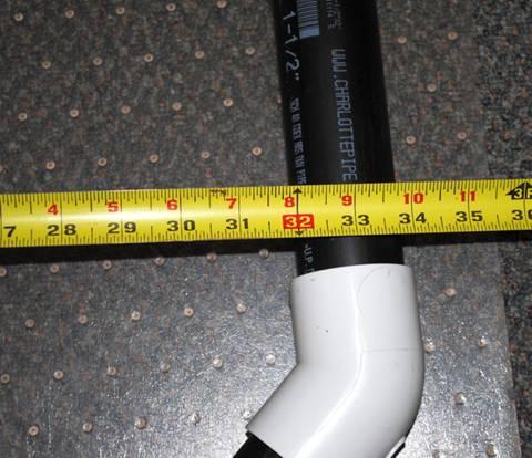
15 Copper foil/flashing: 3 inches wide X.008 thick (8 mils), Soft anneal. Less than 8 mils will cause heat loss resulting in poor efficiency. Efficiency is the ratio of Radiation Resistance to IR losses. Material that has a large RF Skin area is required while still thick enough to handle VERY LARGE circulating currents. Unfortunately this is hard to find and very expensive in small quantities. I have found that suppliers do not want to deal in the lengths required. I have had to purchase large quantities of this material to get cost effective. Please me if you need options for the copper flashing. K8NDS@HLMAGNETICLOOPANTENNAS.COM PVC: 2 inch schedule 40 PVC has approx 2.25 inch OD. This size is required for the 80/30 meter version. The diameter is required to achieve the necessary inductance of the overall loop diameter. Vacuum Capacitor: At least a range of 10 pf to 250. If you use the loop formula it will indicate that you need more C but the helical winding brings that capacitor value down. To be safe I would purchase 10/300pf version. A 10 to 500 pf version could be utilized in case you might want a larger cap for future development. More precise control will be realized with the 10/300pf using my helical wound design. The ratio of capacitance to the gear ratio of capacitance to turns will smooth out fine tuning. The voltage rating should be 15 at least 40 to 50 amps. Many of the Vacuum Capacitors especially surplus units are drastically under rated. Some are capable of double the posted rating. Check this out with the supplier. 15 kv is possible across this capacitor running 1KW. If a 25 KV version can be located, it would be the best choice. The SSB or CW modes and respective duty cycles actually allow the use of smaller KV values. If you plan on running key down, AM or high power digital modes you may want to reduce your power output to 500 watts continuous. Tuner Mounting Board: An inexpensive easy to purchase material is a cutting board from Walmart. About 7 to 8 dollars can buy a durable cutting board that is a very good insulator (White/opaque) in color. It can easily be cut down to size to mount the motor/drive system and capacitor. Capacitor Clamps: Use some ingenuity here depending on the type of Vacuum cap that you acquire. As can be seen in my photos electrical conduit clamps are used on one unit. Care must be taken that the clamps are very tight and making a very positive connection; the use of copper flashing in between the clamps and the cap just to make (15 of 18)9/11/ :24:38

16 sure. Drive System: In viewing my photos it can be seen that a geared 12 volt DC motor, reversible. If this your choice a means of keeping track of position in the range of the capacitor is necessary, if care is not implemented here you will either jam the cap to one end or unscrew the shaft at the other end depending on the cap construction. Utilizing ingenuity/design limit switches can be employed in the control circuit. There are Magnetic loop sites on the net which have accomplished this method. I just keep track of the band of operation, I have never dead ended the system yet but that is me; this is not the recommended way to travel. This was my prototype version; I am currently working on stepper motor controls for fast and precise tuning. Keep in touch with my web site and I will post updates. SO 239: Pay attention to my instruction and photos on how to mount the SO-239, once the PVC is glued together it will be difficult to repair. Radiating the Cows! Hi Hi. (16 of 18)9/11/ :24:38

17 The author/ Designer Rich K8NDS Thank You for reading the article. I hope that you have as much fun with these stealth antennas as I have had. It is a way for the HOA restricted Amateur operator to come very close to the performance of full size antennas. Please look me up if you want to see these antennas in action, I think you will be quite surprised at the functionality of these small antennas. Many on the bands have heard these already and have stated how good the signals were in amazement! You can find me whenever I am active on the bands by visiting QRZ.com and look up K8NDS Then just click on MY QSX link It will take you to my page where you can see what frequency that I am talking/listening on. Many have already done this. You can also view your own signal (17 of 18)9/11/ :24:38
18 strength there while you are transmitting. (18 of 18)9/11/ :24:38
MAGNETIC LOOP SYSTEMS SIMPLIFIED
 MAGNETIC LOOP SYSTEMS SIMPLIFIED By Lez Morrison VK2SON Many articles have been published and made available on websites recently. Unfortunately they have tended to make construction sound complicated
Portable Magnetic Loop Antenna. KG5EAO Rick Bono
 Portable Magnetic Loop Antenna KG5EAO Rick Bono April 2, 2016 Overview Develop a Portable magnetic loop antenna for use on HF bands running QRP. Portable and easy to deploy Ideally run on the 40m through
Hardware Store 40m Magnetic Loop Antenna for Regional and EMCOM Use. Richard Bono NO5V. QST Antenna Design Competition 80 through 10 meter entry
 Hardware Store 40m Magnetic Loop Antenna for Regional and EMCOM Use Richard Bono NO5V QST Antenna Design Competition 80 through 10 meter entry Overview: This describes a field deployable magnetic loop
6M HALO VERSON II + OPTIONAL 2M GROUND PLANE
 The halo is an omnidirectional, horizontally polarized antenna with about the same gain as a dipole but without the low elevation nulls off the ends (+5.5 to +3.5dBi variation for the Halo vs. +7.9 to
Modifying The Heath HA-14 For 6 Meters Greg Chartrand - W7MY 4/22/07
 Introduction The Heathkit HA-14 was one of the few electron tube linear amplifiers intended for mobile use but few were purchased with the 12 volt mobile power supply. Most hams bought the HA-14 for base
Improved Ionospheric Propagation With Polarization Diversity, Using A Dual Feedpoint Cubical Quad Loop
 Improved Ionospheric Propagation With Polarization Diversity, Using A Dual Feedpoint Cubical Quad Loop by George Pritchard - AB2KC ab2kc@optonline.net Introduction This Quad antenna project covers a practical
MFJ Manual Loop Tuner Considerations
 Pagina 1 0 items Proceed to Secure Checkout All Categories Accessories Analyzers Products Tuners Morse Code / CW Power Supplies Product Search Search! List All Products Site Menu Customer Account Order
Port P able ort Magnet Magne ic Loop Ant An e t nna KG5EAO Rick Bono August Augus 11, 2015
 Portable Magnetic Loop Antenna KG5EAO Rick Bono August 11, 2015 Overview Develop a portable magnetic loop antenna for use on HF bands running QRP. Easy to deploy Ideally run on 40m through 10m bands For
Small Magnetic Loops: A Beginner s Guide WOW! This is a very different antenna!
 Small Magnetic Loops: A Beginner s Guide WOW! This is a very different antenna! Dave Wickert, AE7TD Lake Washington Ham Club November 2018 Meeting 10-Nov-2018 Dayton Hamvention 2017 History Full Size Loops
Some hints/tips on how to assemble nice COAX TRAPS!
 Some hints/tips on how to assemble nice COAX TRAPS! Before we start to assemble our traps, here some general info as introduction : Coax traps are cheap, easy to assemble in a reproducible manner, very
EH-20 20m antenna. By VE3RGW
 EH-20 20m antenna By VE3RGW Equivalent circuit of EH-20 antenna system. Upper cylinder Lower cylinder Phasing coil Common mode radiator Tune coil RF choke or 14MHz trap 50ohm coaxial cable 0-150pF (case
The 2 meter Hentenna
 The 2 meter Hentenna (No Tuning Required!) While browsing through my new copy of Simple and Fun Antennas for Hams one day in the Spring of 2003, I discovered an interesting looking design, with an interesting
Tarheel Antennas, Inc.
 Tarheel Antennas, Inc. Instruction Manual for the Model 40A-HP Continuous Coverage HF Antenna PROUDLY MADE IN THE UNITED STATES OF AMERICA 18511 CR 304 St. Joseph, MO 64505 816-671-9409 / 816-364-2619
The EMCOMM Easytenna
 The EMCOMM Easytenna This document will detail how to build an easy to install multiband dipole type antenna for emergency communications using the NVIS propagation mode. History The NVIS mode is one in
Pacific Antenna 20 and 40M Lightweight Dipole Kit
 Pacific Antenna 20 and 40M Lightweight Dipole Kit Antenna diagram showing configuration and lengths when assembled 7 8 16 9 16 9 Description The Pacific Antenna lightweight dual band dipole kit provides
Tarheel Antennas, Inc.
 Tarheel Antennas, Inc. Instruction Manual for the Model 100A-HP Continuous Coverage HF Antenna PROUDLY MADE IN THE UNITED STATES OF AMERICA 18511 CR 304 St. Joseph, MO 64505 816-671-9409 / 816-364-2619
Magnetic Loop Antenna - Topbands
 Magnetic Loop Antenna - Topbands Instruction Manual Thank you for purchasing this new product small Magnetic Loop Antenna Topbands. Manual contains important information. Please read all instructions carefully
Tarheel Antennas, Inc.
 Tarheel Antennas, Inc. Instruction Manual for the Model 300A Continuous Coverage HF Antenna PROUDLY MADE IN THE UNITED STATES OF AMERICA 18511 CR 304 St. Joseph, MO 64505 816-671-9409 / 816-364-2619 Fax
1.5 kw Automatic Remote Controlled Antenna Tuner for Verticals and other Unbalanced Antennas
 1.5 kw Automatic Remote Controlled Antenna Tuner for Verticals and other Unbalanced Antennas Mod. AT- 615U Short Form Manual 10/2010 Dipl.Ing. Klaus Bemmerer RF Communication Electronics Niendorf-Middeldor
Magnetic Loop Antenna - Top Bands
 Magnetic Loop Antenna - Top Bands Instruction Manual Thank you for purchasing this new product small Magnetic Loop Antenna Top Bands. Manual contains important information. Please read all instructions
A Transmatch for Balanced or Unbalanced Lines
 A Transmatch for Balanced or Unbalanced Lines Most modern transmitters are designed to operate into loads of approximately 50 Ω. Solid-state transmitters produce progressively lower output power as the
Installation Instructions Hustler 6-BTV Trap Vertical
 Installation Instructions Hustler 6-BTV Trap Vertical ASSEMBLY 1. Check the package contents against the parts list on page 2. 2. WARNING. Installation of this product near power lines is dangerous. For
Multiband Vertical Antenna Project 2004 by Harold Melton, KV5R
 2004 by Harold Melton, KV5R Page 1 of 5 Printed 1/14/2004 05:02:00 PM Multiband Vertical Antenna Project 2004 by Harold Melton, KV5R Purpose If you could only have two antennas, what would they be? It
High Performance 40 Meters Vertical Without Radials
 High Performance 40 Meters Vertical Without Radials This shortened easy-to-build vertical, with no-radials, is made from surplus military camouflage poles. It has gain and wave angle comparable to a full-sized
Basic Wire Antennas. Part II: Loops and Verticals
 Basic Wire Antennas Part II: Loops and Verticals A loop antenna is composed of a single loop of wire, greater than a half wavelength long. The loop does not have to be any particular shape. RF power can
Installation Instructions Hustler 6-BTV Trap Vertical
 Installation Instructions Hustler 6-BTV Trap Vertical ASSEMBLY 1. Check the package contents against the parts list on page 2. 2. WARNING. Installation of this product near power lines is dangerous. For
VE7CNF - 630m Antenna Matching Measurements Using an Oscilloscope
 VE7CNF - 630m Antenna Matching Measurements Using an Oscilloscope Toby Haynes October, 2016 1 Contents VE7CNF - 630m Antenna Matching Measurements Using an Oscilloscope... 1 Introduction... 1 References...
A short, off-center fed dipole for 40 m and 20 m by Daniel Marks, KW4TI
 A short, off-center fed dipole for 40 m and 20 m by Daniel Marks, KW4TI Version 2017-Nov-7 Abstract: This antenna is a 20 to 25 foot long (6.0 m to 7.6 m) off-center fed dipole antenna for the 20 m and
QEG Instructions for Engineers
 QEG Instructions for Engineers By James Robitaille FTW QEG Engineering Artist -Exciter Coil -Tuning -Core Conditioning -Power Conversion Greetings and Blessings to all our supporters! In lieu of the fact
The below identified patent application is available for licensing. Requests for information should be addressed to:
 DEPARTMENT OF THE NAVY OFFICE OF COUNSEL NAVAL UNDERSEA WARFARE CENTER DIVISION 1176 HOWELL STREET NEWPORT Rl 02841-1708 IN REPLY REFER TO Attorney Docket No. 300104 25 May 2017 The below identified patent
Portable Magnetic Loop Antennas
 Portable Magnetic Loop Antennas Ham Radio s Best Kept Secret By: Kurt Eversole KE9N Topics Why a Small MagneticLoop? What is a Small MagneticLoop? Build orbuy? Design Considerations Building Tips Operating
TYPE SE and TSE, SILICON CARBIDE SPIRAL HEATING ELEMENTS
 TYPE SE and TSE, SILICON CARBIDE SPIRAL HEATING ELEMENTS GENERAL DESCRIPTION The spiral Starbars are made of special high-density reaction-bonded silicon carbide. A spiral slot in the hot zone reduces
BARRETT. 911 Automatic antenna tuner Installation instructions. General. Specifications COMMUNICATIONS
 BARRETT COMMUNICATIONS 0 0 0 Automatic antenna tuner Installation instructions Diameter = mm Connection 0 BARRETT AUTOMATIC ANTENNA TUNER General 0 Control Cable Gland Ground Connection The Barrett Automatic
C.M.HOWES COMMUNICATIONS CTU150 Instructions
 CTU150 Instructions The HOWES CTU150 is an antenna matching unit for use with shortwave transmitters and receivers. A novel constructional method is used - all parts being mounted on a Printed Circuit
Miniature Magnetic Loops By David Posthuma, WD8PUO
 Miniature Magnetic Loops By David Posthuma, WD8PUO Application Notes and Articles A General Overview After several years of curiosity and several months of research, I recently built two magnetic loops.
160- and 80-Meter Matching Networks for your 43-foot Vertical Phil Salas AD5X
 160- and 80-Meter Matching Networks for your 43-foot Vertical Phil Salas AD5X 43-foot verticals have become popular as they can be self supporting, are not too obtrusive, and have higher radiation resistance
Build a 12/17 Meter Trap Dipole Phil Salas AD5X
 Build a 12/17 Meter Trap Dipole Phil Salas AD5X Introduction Why a 12/17 meter rotatable dipole? Well, many folks have verticals for the lower bands, and multi-band dipoles or beams for 20-, 15-, and 10
TZ-RD-1740 Rotary Dipole Instruction Manual
 TZ-RD-1740 17/40m Rotary Dipole Instruction Manual The TZ-RD-1740 is a loaded dipole antenna for the 40m band and a full size rotary dipole for the 17m band. The antenna uses an aluminium radiating section
The Small Wonder 2m Antenna. A tiny 2m roof-top base-station vent-pipe antenna with the gain of a J-pole that your neighbors will never notice.
 The Small Wonder 2m Antenna A tiny 2m roof-top base-station vent-pipe antenna with the gain of a J-pole that your neighbors will never notice. by John Portune W6NBC The secret of stealth, whether for magic
his report is my recent analysis of the EH antenna using the Pspice program and considering the antenna as a set of circuit elements.
 his report is my recent analysis of the EH antenna using the Pspice program and considering the antenna as a set of circuit elements. The antenna can be considered as a set of circuit elements because
PAC-12 Kit Contents. Tools Needed Soldering iron Phillips screwdriver Wire stripper Wrenches, 7/16 and 1/2 Terminal crimp tool Pliers Solder
 PAC-2 Kit Contents Part Quantity Screws: 8/32 x 3/8 Screws: 8-32 x 5/6 Screw: 8-32 x /4 #8 internal tooth washers #8 solder lug ring terminals Bolt: Aluminum, /4-20 x.5 /4 internal tooth washer Nut: Aluminum
MFJ-219/219N 440 MHz UHF SWR Analyzer TABLE OF CONTENTS
 MFJ-219/219N 440 MHz UHF SWR Analyzer TABLE OF CONTENTS Introduction...2 Powering The MFJ-219/219N...3 Battery Installation...3 Operation Of The MFJ-219/219N...4 SWR and the MFJ-219/219N...4 Measuring
RFID. Technical Training. Low Frequency Antenna Design. J.A.G Jan 2009 Texas Instruments Proprietary Information 1
 Technical Training Low Frequency Antenna Design J.A.G Jan 2009 Texas Instruments Proprietary Information 1 Custom Antenna Design There are many reasons why integrators may wish to make their own Low Frequency
K1FO 12 ELEMENT 144/147 MHz YAGI
 K1FO 12 ELEMENT 144/147 MHz YAGI WARNING: INSTALLATION OF THIS PRODUCT NEAR POWER LINES IS DANGEROUS. FOR YOUR SAFETY FOLLOW THE INSTALLATION DIRECTIONS. Ariane Arrays, Inc. Copyright 2006 201 Hopedale
Technician Licensing Class T9
 Technician Licensing Class T9 Amateur Radio Course Monroe EMS Building Monroe, Utah January 11/18, 2014 January 22, 2014 Testing Session Valid dates: July 1, 2010 June 30, 2014 Amateur Radio Technician
80 M 6 Foot EH Antenna
 80 M 6 Foot EH Antenna WB5CXC This is a picture my EH antenna for 80 meters. It has two cylinders made from aluminum flashing 30 1/2" long, wrapped around 2" (2.375") PVC pipe. Below the pipe are two coils
Technician Licensing Class. Antennas
 Technician Licensing Class Antennas Antennas A simple dipole mounted so the conductor is parallel to the Earth's surface is a horizontally polarized antenna. T9A3 Polarization is referenced to the Earth
AD5X. Low Cost HF Antennas & Accessories. Phil Salas - AD5X Phil Salas AD5X. Richardson, Texas
 Low Cost HF Antennas & Accessories Phil Salas - AD5X ad5x@arrl.net PVC Tubing PVC pipe: Considers the inside diameter (ID) of the pipe. For PVC pipe (schedule 40): 1/2" PVC pipe has an ID of 0.6" and an
Users Manual. 200W HF/50MHz Band Auto Antenna Tuner. Model HC-200AT
 Users Manual 200W HF/50MHz Band Auto Antenna Tuner Model HC-200AT Caution 1. Never remove or open the tuner cover while transmitting. When there is RF in the circuits of the tuner, there will be high voltage
A High Efficiency Extended Length Mobile Antenna
 A High Efficiency Extended Length Mobile Antenna By W5JGV February 12, 2006 Loading Coil Data Updated 23 July 2010 What amateur operator running mobile has not lusted for a bigger and better antenna? Well,
M2 Antenna Systems, Inc. Model No: 2M7
 M2 Antenna Systems, Inc. Model No: 2M7 SPECIFICATIONS: Model... 2M7 Frequency Range... 144 To 148 MHz *Gain... 12.3 dbi Front to back... 20 db Typical Beamwidth... E=43 H=50 Feed type... T Match Feed Impedance....
Microair Avionics Pty Ltd ABN VHF Aerial Installation FAQ
 Pty Ltd ABN 92 091 040 032 P O Box 5532 Airport Drive Bundaberg West Queensland 4670 Australia Phone: Fax: Email: Web: 07 4155 3048 +61 7 4155 3048 07 4155 3049 +61 7 4155 3049 support@microair.com.au
A High Efficiency Extended Length Mobile Antenna
 By W5JGV February 12, 2006 Loading Coil Data Updated 23 July 2010 What amateur operator running mobile has not lusted for a bigger and better antenna? Well, so did I, and this is the result... http://w5jgv.com/mobile_antenna/index.htm
Induction Heater Coil Kit Compact low voltage, high current induction coil
 Induction Heater Coil Kit Compact low voltage, high current induction coil Model: CT-400-KIT Features and Specifications High power water cool-able copper coil PCB Layout designed to reduce eddy losses
Device Interconnection
 Device Interconnection An important, if less than glamorous, aspect of audio signal handling is the connection of one device to another. Of course, a primary concern is the matching of signal levels and
MFJ-949E. tuner antenowy skrzynka antenowa. Instrukcja obsługi. importer:
 Instrukcja obsługi MFJ-949E tuner antenowy skrzynka antenowa importer: PRO-FIT Centrum Radiokomunikacji InRadio ul. Puszkina 80 92-516 Łódź tel: 42 649 28 28 e-mail: biuro@inradio.pl www.inradio.pl MFJ-949E
MODERN AM BROADCAST STATIONS AM STEREO CQUAM WITH DDS
 MODERN AM BROADCAST STATIONS AM STEREO CQUAM WITH DDS DDS EXCITER OPERATING MANUAL 20W CARRIER - 80W PEP WHAT IS DDS? IT IS THE INITIALS OF THE WORDS DIRECT DIGITAL SYNTHESIZER. THAT MEANS: DIRECT DIGITAL
REP Design LLC. 193 Winding Ridge Rd, Southington, CT INSTALLATION INSTRUCTIONS:
 REP Design LLC 193 Winding Ridge Rd, Southington, CT 06489 1-860.426.1894 n7emw@cox.net www.repdesign.us INSTALLATION INSTRUCTIONS: SHD-SO239 Super Heavy Duty SO-239Antenna Mounting System Thank you for
Antenna Design for FM-02
 Antenna Design for FM-02 I recently received my FM-02 FM transmitter which I purchased from WLC. I researched the forum on what antennas where being used by the DIY community and found a nice write-up
Pacific Antenna 20 and 40M Lightweight Dipole Kit
 Pacific Antenna 20 and 40M Lightweight Dipole Kit Diagram showing configuration and approximate lengths 8 3 16 9 16 9 8 3 Description The Pacific Antenna lightweight dual band, trap dipole kit provides
Chapter 6 Antenna Basics. Dipoles, Ground-planes, and Wires Directional Antennas Feed Lines
 Chapter 6 Antenna Basics Dipoles, Ground-planes, and Wires Directional Antennas Feed Lines Some General Rules Bigger is better. (Most of the time) Higher is better. (Most of the time) Lower SWR is better.
4/25/2012. Supplement T9. 2 Exam Questions, 2 Groups. Amateur Radio Technician Class T9A: T9A: T9A: T9A:
 Amateur Radio Technician Class Element 2 Course Presentation ti ELEMENT 2 SUB-ELEMENTS Technician Licensing Class Supplement T9 Antennas, Feedlines 2 Exam Questions, 2 Groups T1 - FCC Rules, descriptions
Ameritron RCS-10 INTRODUCTION
 Ameritron RCS-10 INTRODUCTION The RCS-10 is a versatile antenna switch designed for 50-ohm systems. It handles high power, and sealed relays offer excellent life and connection reliability. It requires
SoftRock v6.0 Builder s Notes. May 22, 2006
 SoftRock v6.0 Builder s Notes May 22, 2006 Be sure to use a grounded tip soldering iron in building the v6.0 SoftRock circuit board. The soldering iron needs to have a small tip, (0.05-0.1 inch diameter),
FCC Technician License Course
 FCC Technician License Course 2014-2018 FCC Element 2 Technician Class Question Pool Presented by: Tamiami Amateur Radio Club (TARC) WELCOME To the third of 4, 3-hour classes presented by TARC to prepare
A Guide to building your own Portable Station Incorporating a ¼ Wave Vertical Antenna and a Ground Tuning Unit or GTU
 A Guide to building your own Portable Station Incorporating a ¼ Wave Vertical Antenna and a Ground Tuning Unit or GTU Date: 06.02.2016 By: Alex Ball VK2HAS Credits: I was introduced to the GTU by Dave
Definitions of Technical Terms
 Definitions of Technical Terms Terms Ammeter Amperes, Amps Band Capacitor Carrier Squelch Diode Dipole Definitions How is an ammeter usually connected = In series with the circuit What instrument is used
How to use your antenna tuner.
 How to use your antenna tuner. There's more to it than what is in your manual or on most how to do it websites! http://www.arrl.org/tis/info/ant-tuner-op.html Here is a neat site with a "T" network simulator.
Technician License. Course
 Technician License Course Technician License Course Chapter 4 Lesson Plan Module - 9 Antenna Fundamentals Feed Lines & SWR The Antenna System The Antenna System Antenna: Transforms current into radio waves
M2 Antenna Systems, Inc. Model No: 2M4
 M2 Antenna Systems, Inc. Model No: 2M4 SPECIFICATIONS: Model... 2M4 Frequency Range... 144 To 148 MHz *Gain... 9.6 dbi Front to back... 20 db Typical Beamwidth... E=54 H=74 Feed type... T Match Feed Impedance....
9 Element Yagi for 2304 MHz
 9 Element Yagi for 2304 MHz Steve Kavanagh, VE3SMA Design Dipole-based Yagi designs for 2304 MHz are rare, partly because they are a bit tricky to build and partly because the loop yagi has completely
Pacific Antenna 20 and 40M Lightweight Dipole Kit
 Pacific Antenna 20 and 40M Lightweight Dipole Kit Diagram showing configuration and approximate lengths 8 6 16 9 16 9 8 6 Description The Pacific Antenna lightweight dual band, trap dipole kit provides
Antenna. NO5V Rick Bono
 Portable End Fed Half Wave Antenna NO5V Rick Bono October 15, 2016 Overview Develop a Portable End Fed Half Wave Antenna Portable and easy to deploy Multiband capability Resonant Antenna No Tuner Needed!
VECTRONICS HFT-1500 Digital Bargraph Antenna Tuner
 Table of Contents FEATURES... 1 SPECIFICATIONS... 1 FRONT PANEL INDICATORS AND CONTROLS... 1 CONTROLS... 1 REAR PANEL CONNECTORS... 1 OTHER... 2 CONTOLS / CONNECTORS... 2 FRONT PANEL FUNCTIONS... 2 REAR
A 75-Watt Transmitter for 3 Bands Simplified Shielding and Filtering for TVI BY DONALD H. MIX, W1TS ARRL Handbook 1953 and QST, October 1951
 A 75-Watt Transmitter for 3 Bands Simplified Shielding and Filtering for TVI BY DONALD H. MIX, W1TS ARRL Handbook 1953 and QST, October 1951 The transmitter shown in the photographs is a 3-stage 75-watt
Performance Predicted by YAGI-CAD
 1 of 7 11/16/2010 2:02 PM Joe Leggio WB2HOL Description This antenna evolved during my search for a beam with a really great front-to-back ratio to use in hidden transmitter hunts. This design exhibits
Variable Frequency Drive Noise Reduction, Version 2.1
 Variable Frequency Drive Noise Reduction, Version 2.1 By R. G. Sparber Protected by Creative Commons. 1 Conclusion My Variable Frequency Drive (VFD) plus its spindle motor generated enough noise to destabilize
One I had narrowed the options down, I installed some wire and started testing.
 Loft & Attic antennas for restricted spaces - M. Ehrenfried G8JNJ I ve recently been looking at designs for an efficient antenna that would fit in a loft. I hoped to find something that would work on with
INSTRUCTION MANUAL. Specifications Mechanical. 1 5/8 to 2 1/16 O.D. (41mm to 52mm)
") 308 Industrial Park Road Starkville, MS 39759 USA Ph: (662) 323-9538 FAX: (662) 323- General Description Model VB-25FM 2-Meter 5 Elements Beam INSTRUCTION MANUAL This antenna is a 5-element, 2-meter beam
308 Industrial Park Road Starkville, MS 39759 USA Ph: (662) 323-9538 FAX: (662) 323- General Description Model VB-25FM 2-Meter 5 Elements Beam INSTRUCTION MANUAL This antenna is a 5-element, 2-meter beam
AD5X. The 43-Foot Vertical. Phil Salas - AD5X Phil Salas AD5X. Richardson, Texas
 The 43-Foot Vertical Phil Salas - AD5X ad5x@arrl.net Outline Why a vertical? Ground Losses and Antenna Efficiency Why a 43-foot vertical? SWR-related coax and unun losses Matching Networks for 160- and
Conversion of a Marconi Blue Cap LNB into a 3cms 30-50mW Tx.
 Conversion of a Marconi Blue Cap LNB into a 3cms 30-50mW Tx. These mods. are based on the article by Bob Platts, G8OZP, in CQ-TV 181 P64-68. In this variation the various bias voltages are generated from
MFJ-969 Versa Tuner II Instruction Manual
 MFJ-969 Versa Tuner II Instruction Manual General Information The MFJ-969 is a 300 watt RF output power antenna tuner that will match any transmitter or transceiver to virtually any antenna. Peak or average
Adapting a 160m Inverted-L for 630m
 Adapting a 160m Inverted-L for 630m In 2017 the FCC opened up the 630m and 2200m bands for Amateur Radio use with some minor conditions as explained in this ARRL article http://www.arrl.org/news/new-bands-fcc-issues-amateurradio-service-rules-for-630-meters-and-2-200-meters.
RF Current Meter Kit
 Kit When assembled, this kit provides you with a simple but effective means of measuring the current in antenna wires, and of looking for braid currents on coax feeders. The more current you can get flowing
Page 1The VersaTee Vertical 60m, 80m Modular Antenna System Tutorial Manual
 Page 1The VersaTee Vertical 60m, 80m Modular Antenna System Tutorial Manual by: Lou Rummel, KE4UYP Page 1 In the world of low band antennas this antenna design is unique in many different ways. 1. It is
A IVE-BAND, TWO-ELEMENT H QUAD
 A IVE-BAND, TWO-ELEMENT H QUAD Two quad designs are described in this article, both nearly identical. One was constructed by KC6T from scratch, and the other was built by Al Doig, W6NBH, using modified
20m G4BUD Mobile Whip
 This particular antenna was built specifically to take on holiday to Fuerteventura in the Canary Islands, after it was originally tested from an inland site in the UK. Amongst my first contacts using the
JC-5 4KW PEP, 1KW RMS AUTO ANTENNA COUPLER
 JC-5 4KW PEP, 1KW RMS AUTO ANTENNA COUPLER 1) DIRECTLY CONTROLLED BY ICOM, ALINCO & KENWOOD. 2) INDEPENDENT CAPACITOR INPUT AND OUTPUT BLOCKS! 3) 3 mm COIL WIRE & INTERNAL FAN FOR THE BIG COILS! 4) DIPPED
2-element Single Mast Wire Beam with 4 Switchable Directions
 2-element Single Mast Wire Beam with 4 Switchable Directions Chavdar Levkov Jr. LZ1ABC, ch.levkov@gmail.com, Chavdar Levkov LZ1AQ, lz1aq@abv.bg We need a directional antenna field day style for 20 m band.
Removing and Replacing the Y-truck
 Service Documentation Removing and Replacing the Y-truck To remove and replace the Y-truck you will need the following tools: 4mm Allen wrench 12mm stamped flat wrench #2 Phillips screwdriver (magnetic
Pacific Antenna SLT+ Switched Long wire Tuner
 Pacific Antenna SLT+ Switched Long wire Tuner The SLT+ is designed to match the high impedance load of an end feed, half wave antenna wire to a 50 ohm transmitter using manually switched inductors and
User Guide for the Alpha Loop Sr Antenna
 User Guide for the Alpha Loop Sr Antenna Manufactured by: Alpha Antenna 1.888.482.3249 Website: http://alphaantenna.com Available from: Amateur Radio Store Website: https://amateurradiostore.com User Guide
The DBJ-1: A VHF-UHF Dual-Band J-Pole
 By Edison Fong, WB6IQN The DBJ-1: A VHF-UHF Dual-Band J-Pole Searching for an inexpensive, high-performance dual-band base antenna for VHF and UHF? Build a simple antenna that uses a single feed line for
Assembly Instructions for the FRB FET FM 70 Watt Amp
 Assembly Instructions for the FRB FET FM 70 Watt Amp 1.) Orient the circuit board with the diagram 2.) Use a narrow chisel tip 25-30 watt soldering iron for assembly 3.) All the small parts are taped onto
The Switched Longwire Tuner SLT
 The Switched Longwire Tuner SLT Thank you for purchasing the SLT kit from Hendricks QRP Kits. This kit is a very high quality kit that you will find easy to build, yet when you finish, you will have a
(Revised March 16, 1922.) CONSTRUCTION AND OPERATION OF A VERY SIMPLE RADIO RECEIVING EQUIPMENT.*
 CONSTRUCTION AND OPERATION OF A VERY SIMPLE RADIO RECEIVING EQUIPMENT.*") - 1 - JPL:HH I-6 Publication of the DEPARTMENT OF COMMERCE BUREAU OF STANDARDS WASHINGTON (Revised March 16, 1922.) CONSTRUCTION AND OPERATION OF A VERY SIMPLE RADIO RECEIVING EQUIPMENT.* Prepared at the
- 1 - JPL:HH I-6 Publication of the DEPARTMENT OF COMMERCE BUREAU OF STANDARDS WASHINGTON (Revised March 16, 1922.) CONSTRUCTION AND OPERATION OF A VERY SIMPLE RADIO RECEIVING EQUIPMENT.* Prepared at the
M2 Antenna Systems, Inc. Model No: 2M5WL
 M2 Antenna Systems, Inc. Model No: 2M5WL SPECIFICATIONS: Model... 2M5WL Frequency Range... 144 To 148 MHz *Gain... 16.84 dbi Front to back... 22 db Typical Beamwidth... E=26 H=29 Feed type... T Match Feed
Standard Kit #1 (5-way switch)
") Standard Kit #1 (5-way switch) Please Read All Instructions Before Beginning. Tools you will need: Soldering Iron (35 watt preferably) Solder Wet Sponge Wire Clippers 3/8 Drill Bit 1/4 Drill Bit Variable
Standard Kit #1 (5-way switch) Please Read All Instructions Before Beginning. Tools you will need: Soldering Iron (35 watt preferably) Solder Wet Sponge Wire Clippers 3/8 Drill Bit 1/4 Drill Bit Variable
Technician License Course Chapter 4. Lesson Plan Module 9 Antenna Fundamentals, Feed Lines & SWR
 Technician License Course Chapter 4 Lesson Plan Module 9 Antenna Fundamentals, Feed Lines & SWR The Antenna System Antenna: Transforms current into radio waves (transmit) and vice versa (receive). Feed
Combat Foamie. An electric powered model made from sheet foam for full contact combat matches. Designed by. Plan by Paul Bradley. Jerry W.
 Combat Foamie An electric powered model made from sheet foam for full contact combat matches Designed by Jerry W. Hagood Plan by Paul Bradley July 2010 Combat Foamie Top View 22.9 CG is 7.3 back from nose