CoolBLUE Inductive Absorbers NaLA Noise Line Absorbers
|
|
|
- Willis Griffin
- 6 years ago
- Views:
Transcription


1 CoolBLUE Inductive Absorbers NaLA Noise Line Absorbers Motor Bearing Solution from MH&W International Corp.
2 Variable Frequency Motor Drive Systems 1. What is the problem 2. Testing the system 3. What solves the problem (Temporary fix, or solid solution) 4. Tools 5. Real industry solutions 2
3 Variable Frequency Motor Drive Systems The Variable Frequency Drive (VFD) was created approximately 30+ years ago to provide substantial energy savings and precise control in commercial and industrial applications. Necessary changes from traditional markets of fossil fuel have led to markets for alternative power generation as well. All of these markets have benefitted from VFD s. Advantages of VFD s 1. Fast switching 2. Speed variation 3. Heavy load inertia starting 4. High starting torque requirements 5. Low starting current requirements 6. High efficiency at low speed 7. High power factor 8. Lower power 3

4 Problems with IGBT Systems VFD systems are not sinusoidal but are a continuous generation of pulses (Pulse Width Modulation or PWM). The pulses have a constant voltage and a dv/dt rise and fall time of the pulse. The original VFD systems were based on Bipolar Junction Transistors. The trend now is toward IGBT (Insulated Gate Bipolar Transistor from On Semi, Infineon, ST Micro, etc.) systems which give a faster switching dv/dt with lower switching losses and a more efficient drive. IGBT systems create problems associated with the system performance. The IGBT introduces parasitic currents in the form of two potential destructive characteristics: a. Transient Voltage/ Harmonic Distortion/Reflective Waves b. Higher magnitudes of electrical ground noise current 4

5 Electrical Discharge Machining AC Motor Drive systems utilizing variable frequency controls produce high frequency electrical noise. The noise is superimposed on the power drive lines of the motors in the form of common mode noise. The common mode noise creates a voltage (dv/dt) across the rotor/stator of the motor resulting in a discharge current through the lubrication and motor bearings to the motor raceway. This current discharge produces an EDM effect (Electrical Discharge Machining) that causes destructive pitting and damage to the motor raceway, and premature lubrication breakdown. The end result is premature failure of the motor causing expensive repairs and system downtime. Example: Outer Bearing Race Fluting EDM Results from VFD Induced Common Mode Noise 5
6 Problems with IGBT Systems Each pulse in a PWM system is not a clean square pulse. Each Rise and Fall of the pulse has an over shoot or transient over voltage. This over voltage phenomenon is also known as "Reflected Wave", "Transmission Line Effect" or "Standing Wave". The per unit overvoltage magnitude is dependent upon drive cable motor circuit dynamics defined by drive output voltage magnitude and rise time, cable surge impedance characteristics, motor surge impedance to the pulse voltage, cable length and spacing of the train of pulses by the PWM modulator. 6


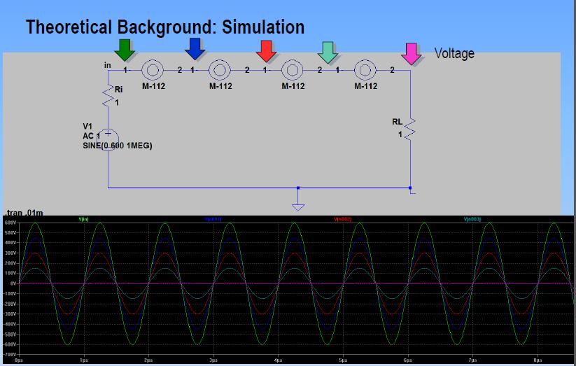
7 Example of High Frequency Noise Here is a typical example of the high frequency noise generated by the IGBT devices in a motor system. The yellow line at top of screen indicates the switching of the IGBT in the drive. The green line indicates the high frequency noise generated creating the destructive common mode currents. 7
8 Example of High Frequency Noise As the frequency of the common mode noise increases, the impedance of the system goes down. This graph shows how low the impedance goes as the frequency increases from Hz to MHz. The decrease in the impedance allows more and more current to flow. 8

, and measures the common mode current.")
9 Determining the Problem MH&W suggests using a flexible, clip-around current probe to measure high frequency destructive common mode currents in motor drives... high frequencies produced by motor drive IGBT s in the khz up to several MHz s. The high frequency Rogowski coil simply attaches around the 3 power phases of cable going from the drive to the motor. The output of the Rogowski coil connects to any oscilloscope (suggested 40MHz and above), and measures the common mode current. Very minimal downtime is needed in order to measure current. Simply power down, place the red Rogowski coil around 3 phases of power. Power upsystem. Measure current. 9


10 Determining the Problem The electrical discharge in a motor bearing is a charge-discharge similar to a spark. A large current is flowing from a high potential to ground. This spark, or arc, generates a high frequency noise that can be detected. A test instrument with antennae can sense every time the spark is generated. One such piece of test equipment is the SKF EDD test equipment, model TKED 1. Holding the TKED 1 close to the motor where the motor bearings are located, the equipment measures every discharge. This is a safe method of identifying potential problems in that there is no contact with the motor. 10
11 Determining the Problem Shaft Grounding There are methods of testing the voltage discharge from shaft to ground by use of brush or wire attached to an oscilloscope probe. While this may be effective for measuring voltage, it creates several issues: 1. Method of testing with brush probe is dangerous, and sometimes not accessible, especially in vertical mount motors. A large number of corporations forbid this type of field testing due to safety concerns. 2. The shaft has to be cleaned and prepped in order to make a good contact. 3. Not all systems in the field are accessible. 4. Downtime of system obtaining access to shaft, preparation of shaft, installing probe, powering system up, powering system down, and disconnecting probe. 5. While voltage is part of the formula for system failures, watts are the destructive force (V * I = Watts). For example, 30 volts times 1 amp is 30 Watts of power. 30 volts times.1 amp is only 3 watts. Again, measuring current with a Rogowski coil is the only method for accurately measuring the destructive force in a system. 11
12 Solutions There are three solutions that are commonly employed to solve or correct the effects of power line noise on VFD motor systems: 1. Shaft Grounding Device 2. Insulated Bearings 3. Inductive Absorption Device 12
13 Shaft Grounding Devices This is a mechanical solution whereas devices have a brush or fiber, usually copper or other high conductivity metal, that rides on the motor shaft. Current does not go through the bearing but is instead conducted directly to ground (via motor casing) through the brush. These brushes are especially selected to tolerate misalignment and maintain rotating contact throughout the brush's life when properly maintained. The problems with this solution are: 1. Brushes must be properly maintained/replaced system becomes expensive over time. 2. Brushes lose contact with the shaft over time due to heat, contaminants, and physical wear. 3. Must be replaced periodically causing downtime for maintenance. 4. This solution only protects the motor bearings. A significant problem in the field is with stray capacitive currents flowing in the system. Shaft grounding just adds to this problem HP and above must have isolated/hybrid bearing on opposite end to force current through brush. Added cost and maintenance time. 6. Method of testing with brush probe is dangerous, and sometimes not accessible. 7. Literally hundreds of choices of solutions. i.e. epoxy, drill and tap, shaft size varies per hp/ kilowatts, wash down applications, chemical/harsh environment resistant, hazardous conditions safety, poor grounding of motor casing. 13

14 Insulated Bearings This is a mechanical solution where the motor bearings are made of an insulated material or insulated coating. This system is effective at avoiding damage to the bearings and the resulting downtime of the motor system. The problems associated with this solution are: 1. Very expensive 2. Motor bearings do have to be replaced, increasing the expense over time 3. This solution only protects the motor bearings 14

15 Inductive Absorption Device Common Mode Choke Inductive absorption is an electrical solution whereas inductive components are placed over the drive cables to absorb the transient voltage and common mode currents. The inductive components need to have high permeability, high saturation, and low power loss. They do not affect the symmetrical power currents but efficiently dampen the asymmetrical EMI noise currents. This creates a common mode choke. The initial installation cost is about the same, or less, as other solutions. The long term costs are negligible as there is no maintenance, or replacement ever needed with this solution. 15


16 The Inductive Absorber - Common Mode Choke Solution The advantages of the Inductive Absorber/Common Mode Choke solution are: 1. Installation cost same, or less, as other solutions 2. Very easy to install around power cables 3. Reduces line noise by a factor of 4:1 or better 4. Can be retrofitted with little or no problem 5. Reduces transient voltages, stray capacitive currents, and common mode currents before they reach the motor system 6. Small number of cores fit all motor applications 7. Electronic devices like sensors are protected as well as motor bearings 8. Lifelong solution magnetic properties do not degrade over time nor affected by heat 16
17 17


18 Correct Installation of CoolBLUE Cores 3 power phases must go through cores as shown below. No grounding wire or shielding. Multiconductor Example In the case of multiple conductors, all power conductors go through cores. Again, not ground or shielding. 18

19 Place the CoolBLUE Cores as Close to VFD as Possible 19

20 Inductive Absorption Device Common Mode Choke Inductive absorption is an electrical solution whereas inductive components are placed over the drive cables to absorb the transient voltage and common mode currents. The inductive components need to have high permeability, high saturation, and low power loss. In some cases, the inductance of the choke needs to be increased by installing more CoolBLUE cores. However, an alternative to adding more cores is to simply increase the inductivity of the cores listed on the design guide. This is necessary on motors up to 10HP/7.5kW. No more than two turns are necessary or suggested. Saturation of cores will occur, and cores will become too hot for normal operation. 20
21 NaLA Nanoperm Line Absorber Servo Motors and High Reliability DC to 100 MHz NaLA Inductive Absorbers increase the reliability of the system by further reducing noise and peak values. In applications up to 10HP, or where high reliability is needed, the use of NaLA differential mode line absorbtion is necessary. The use of NaLA increases the reliability of these systems by further reducing the noise and peak values of current. These cores must be placed around each individual wire. Not around all phases like CoolBLUE. NaLA is to be used in conjunction with CoolBLUE common mode choke cores. 21
22 How Many Cores are Needed per Application 1. Determine the motor size by either horsepower, or kilowatts 2. Determine the cable length 3. Reference VFD Application Guide CoolBLUE cores per power range and cable length 4. Choose either round or oval. The round and oval in each column are exactly the same electrically. Oval shaped is sometimes easier to feed the cables through VFD Application Guide CoolBLUE Cores per power range and cable length CoolBLUE Round M-367 M-367 M-113 M-116 M-117 Round Ver. N/A CoolBLUE Oval M-049 M-049 M-283 M-302 M-111 M-248 Power Range (hp) *1/4-10 (Use with NaLA ) (Use with NaLA ) Cable Length # Cores # Cores # Cores # Cores # Cores # Cores 150ft/50m ft/100m ft/150m ft/300m
23 Important Notes about CoolBLUE Installation Note 1 CoolBLUE normal operation is below 158 F/70 C. It is important to use the correct number of cores to avoid saturation. Note 2 On motors up to 10HP, two turns are needed through the cores (pass cable through cores twice). Note 3 Data in the application guide is for information and guideline purposes. Please contact MH&W Engineering for detailed information. Note 4 Round and oval shaped cores are for ease of installation and mechanical functionality. Round and oval cores have same basic electrical absorption. Note 5 Cores must be installed on the load side of the drive only. If possible, installing cores in a drive cabinet is preferred. Note 6 Do not place conductive wires through the cores for holding cores in place. MH&W offers brackets, and cable ties to hold cores in place. 23
24 NaLA VFD Differential Mode Noise Line Absorbers How Many Cores are Needed per Application 1. Determine the motor size by either horsepower, or kilowatts 2. Determine the cable length 3. Reference VFD Application Guide NaLA cores per power range and cable length 4. Use in conjunction with appropriate CoolBLUE cores. VFD Application Guide NaLA Cores per power range and cable length NaLA Part number M-053 M-102 M-381 M-613 M-614 M-616 Power Range (hp) 1/ over 1631 Cable Length # Cores # Cores # Cores # Cores # Cores # Cores 150ft/50m ft/100m ft/150m ft/300m
25 Important Notes About NaLA Installation Note 1 NaLA normal operation is below 158 F/70 C. It is important to use the correct number of cores to avoid the cores getting hot. Note 2 NaLA cores must go around each individual power cable. Not around all like CoolBLUE. Note 3 Data in the application guide is for information and guideline purposes. Please contact MH&W Engineering for detailed information, if needed. Note 4 Cores must be installed on the load side of the drive only. Note 5 Do not place conductive wires through the cores for holding cores in place. This effectively bypasses the inductive properties of the cores. MH&W offers brackets, and cable ties to hold cores in place. 25


.")
26 CoolBLUE and NaLA Packaging CoolBLUE and NaLA are made up of a Nanocrystalline tape, wound many times. The tape, after processing, is placed inside a premade plastic case. The plastic case provides better performance (no pressure on the core). Handling is much more robust and does not break if dropped. Cost is lower than any other type of performance coating. 26
27 Industry Application Example #1 Example: Industrial paper plant manufacturer with typical 150hp IGBT/motor system 350 AWG per phase cabling. Problem - Customer experiencing random shut downs of system, and premature bearing failures on 150HP motor system. Bearing fluting was evident, and need of repair, every 8 weeks. Successful Solution - 4 each M-116 cores were placed around cabling. Current reduction of over 75% was seen, which resulted in multiple years of no bearing fluting/frosting/etc. failures. Equally important was no more random system shutdowns because of high frequency stray grounding currents. 27

28 Example: Industry Application Example #1 (continued) Paper plant with typical 150hp VFD motor system. The motor cables were shielded and about 100 feet. Current measurements were taken before and after the addition of the Nanocrystalline cores. Four Nanocrystalline cores were placed over the three leads at the output of the inverter inside the shielding. Significant reduction in the noise level of ground current are shown. Both power ground and signal ground share the same common ground. When noise levels on the ground current are high enough, the noise is injected into signal circuits inductively coupled to the common ground. The ground loop current caused by the noise also generates a radio frequency noise that again affects surrounding equipment primarily on the signal lines. CoolBLUE cores absorbed this high frequency noise current, and no more random shutdowns were experienced within the plant on the system. 28
29 Industry Application Example #2 Problem Large chiller manufacturer was experiencing bearing failures within two to four years. Manufacturer opted to use ceramic coated bearings on new builds, and customer repair replacements. Cost was very high to build and replace. Also, customers reported still having failures in short time span. Successful Solution All new systems at factory, and in field rebuilds of ceramic coated bearings systems, are now built with 5 each M-116 cores placed around cabling. Reduction of over 85% was seen in current. End results 6+ years of no bearing fluting/frosting/etc. failures with standard steel bearings. 29
30 Industry Application Example #3 Problem Automotive manufacturer experiencing random shut down of system, multiple system errors, and other manufacturing failures with Ethernet controlled 600HP system. High frequency stray grounding currents evident in system ground because of poor building ground. Premature failure of bearings due to large common mode currents. Solution - 4 each M-117 CoolBLUE cores were placed around cabling for common mode choke to reduce motor bearing wear. 2 each M-614 NaLA cores were placed around each individual cable line to reduce frequency even more, and to substantially reduce stray grounding currents. Success- Bearing currents lowered well below level of destructive force, and no more Ethernet based issues. 30
31 Industry Application Example #4 Problem Multiple office building air handling system failures (30HP) within 2 years of installation. Bearing lubrication degradation and fluting evident when removed and inspected. Successful Solution Reduced common mode current over 83% by placing 3 each M-283 CoolBLUE cores around power cables. 1 each M-102 NaLA cores were placed around each individual cable line to reduce even more of the associated high frequency noise. 31
32 Industry Application Example #5 Problem Mission Critical! Major hospital system in New England. Air handling and pump systems experiencing bearing failures in short period of time. Customer had previously installed shaft grounding rings, but still experiencing failures. Also, unable to install on large vertical mount motors. Operating rooms were critical to keep at constant temperatures. Successful Solution Installed 4 each M-049 CoolBLUE cores around cabling for common mode noise. Bearing currents lowered over 75%. 32


33 Industry Application Example #6 Problem Up to 3MW wind turbine generators experiencing early bearing failures due to high common mode currents. Very high costs associated with bearing replacements! Successful Solution Installed multiple CoolBLUE cores around cabling for common mode noise. Bearing currents lowered over 75%. Without CoolBLUE I CM = up to 40A With CoolBLUE I CM ~ 10A 33
34 Closing Comments CoolBLUE and NaLA has had tremendous success in thousands of installations world wide. CoolBLUE and NaLA are now being used, and promoted, by major OEM drive manufacturers, OEM s, HVAC/chiller equipment, wind turbines, and end users to keep their equipment functioning properly, and avoid downtime. 34
COOLTUBE Radiated Emissions Absorber
 COOLTUBE Radiated Emissions Absorber Radiated Emissions Solution from MH&W International Corp. Radiated Emissions In VFD Motor Systems 1. Defining the problem 2. Solutions 2 What is EMI? What Are Emissions?
SPECIALISTS IN ELECTRO-MECHANICS NORTH FRASER WAY, BURNABY, BRITISH COLUMBIA, V5J 5J2. Service Report
 ARMATURE ELECTRIC LIMITED SPECIALISTS IN ELECTRO-MECHANICS 100 3811 NORTH FRASER WAY, BURNABY, BRITISH COLUMBIA, V5J 5J2 Tel: 604-879-6141 Fax: 604-879-6974 Toll Free: 1-800-539-3556 Toll Free Fax: 877-879-6974
SWF DV/DT Solutions Sinewave Filters. N52 W13670 NORTHPARK DR. MENOMONEE FALLS, WI P. (262) F. (262)
 F. (262)") SWF DV/DT Solutions Sinewave Filters N52 W13670 NORTHPARK DR. MENOMONEE FALLS, WI 53051 P. (262) 754-3883 F. (262) 754-3993 www.apqpower.com Does your application use variable frequency drives for improved
SWF DV/DT Solutions Sinewave Filters N52 W13670 NORTHPARK DR. MENOMONEE FALLS, WI 53051 P. (262) 754-3883 F. (262) 754-3993 www.apqpower.com Does your application use variable frequency drives for improved
Solution of EMI Problems from Operation of Variable-Frequency Drives
 Pacific Gas and Electric Company Solution of EMI Problems from Operation of Variable-Frequency Drives Background Abrupt voltage transitions on the output terminals of a variable-frequency drive (VFD) are
Application Note. Motor Bearing Current Phenomenon. Rev: Doc#: AN.AFD.17 Yaskawa Electric America, Inc August 7, /9
 Application Note Application Note Motor Bearing Current Phenomenon Rev: 08-08 Doc#: AN.AFD.17 Yaskawa Electric America, Inc. 2008 www.yaskawa.com August 7, 2008 1/9 INTRODUCTION Since the introduction
P2 Power Solutions Pvt. Ltd. P2 Power Magnetics. Quality Power within your Reach. An ISO 9001:2008 Company
 P2 Power Solutions Pvt. Ltd. An ISO 9001:2008 Company Quality Power within your Reach P2 Power Magnetics P2 Power Solutions Pvt. Ltd. P2 Power Solutions Pvt. Ltd. provides EMC and power quality solutions,
Motor Bearing Damage and Variable Frequency Drives: - Diagnosing the Causes, - Implementing a Cure, and - Avoiding the Pitfalls
 Motor Bearing Damage and Variable Frequency Drives: - Diagnosing the Causes, - Implementing a Cure, and - Avoiding the Pitfalls Tim Albers, Director of Product Mgt, NIDEC Motor Corporation Tim Jasina,
Cable Solutions for Servo and Variable Frequency Drives (VFD)
") Cable Solutions for Servo and Variable Frequency Drives (VFD) Electric drive systems with continuous torque and speed control are widespread today. They allow an optimal adjustment of the drive with respect
Cable Solutions for Servo and Variable Frequency Drives (VFD) Electric drive systems with continuous torque and speed control are widespread today. They allow an optimal adjustment of the drive with respect
Drives 101 Lesson 3. Parts of a Variable Frequency Drive (VFD)
") Drives 101 Lesson 3 Parts of a Variable Frequency Drive (VFD) This lesson covers the parts that make up the Variable Frequency Drive (VFD) and describes the basic operation of each part. Here is the basics
Drives 101 Lesson 3 Parts of a Variable Frequency Drive (VFD) This lesson covers the parts that make up the Variable Frequency Drive (VFD) and describes the basic operation of each part. Here is the basics
Product Application Note
 Application Note Product Application Note Motor Bearing urrent Phenomenon and 3-Level Inverter Technology Applicable Product: G7 Rev: 05-06 G7 three-level output waveform onventional two-level output waveform
Technical White Paper
 Technical White Paper Increased Reports of Bearing Damage in AC Motors Operating from Modern PWM VFD's Repair shops and motor manufacturers are seeing an increased number of instances where bearings and
Variable Frequency Drives Motor Bearing Failure Mitigation
 Variable Frequency Drives Motor Bearing Failure Mitigation Background Throughout the Commonwealth Campus various motors are controlled by VFDs and the University is seeing a rapid and high failure rate
Direct Current Motor Electrical Evaluation Using Motor Circuit Analysis
 Direct Current Motor Electrical Evaluation Using Motor Circuit Analysis Introduction Howard W. Penrose, Ph.D BJM Corp, ALL-TEST Division Old Saybrook, CT Electrical testing of Direct Current (DC) electric
External Drive Hardware
 US1086e_External Drive Hardware, 08/2010 External Drive Hardware Selection and Application Answers Answers to external hardware questions A soup to nuts list of questions with installation / application
CHAPTER 1 INTRODUCTION
 1 CHAPTER 1 INTRODUCTION 1.1 GENERAL Induction motor drives with squirrel cage type machines have been the workhorse in industry for variable-speed applications in wide power range that covers from fractional
MTE training MTE Corporation
 1 MTE Corporation Improving the Performance and Reliability of Power Electronic Systems 2 MTE solutions to Long lead dive applications Protection of motors drive cables and Variable frequency inverters
Application Note. About VFD Cables Steve Wetzel, Sr. Product Engineer
 Application Note About VFD Cables Steve Wetzel, Sr. Product Engineer A variable-frequency drive (VFD) cable is a special cable construction for the inverter-to-motor cable that has some or all of the following
Technical Guide No. 5. Bearing Currents in Modern AC Drive Systems
 Technical Guide No. 5 Bearing Currents in Modern AC Drive Systems 2 Contents 1 Introduction... General... Avoiding bearing currents... 2 Generating Bearing Currents... High frequency current pulses...
Measuring Reflected Voltage Spikes in VFD Motor Applications
 Keywords: VFD, ASD, impedance mismatch, high frequency, reflected voltage, spikes, over voltage, ringing, cable length, inverter rated motor, turn to turn voltage, electric motor testing, oscilloscope,
CHAPTER 15 GROUNDING REQUIREMENTS FOR ELECTRICAL EQUIPMENT
 CHAPTER 15 GROUNDING REQUIREMENTS FOR ELECTRICAL EQUIPMENT A. General In a hazardous location grounding of an electrical power system and bonding of enclosures of circuits and electrical equipment in the
Pulse Width Modulated Motor Drive Fault Detection Using Electrical Signature Analysis
 Pulse Width Modulated Motor Drive Fault Detection Using Electrical Signature Analysis By ALL-TEST Pro, LLC & EMA Inc. Industry s use of Motor Drives for AC motors continues to grow and the Pulse-Width
A PRACTICAL GUIDE TO UNDERSTANDING BEARING DAMAGE RELATED TO PWM DRIVES
 A PRACTICAL GUIDE TO UNDERSTANDING BEARING DAMAGE RELATED TO PWM DRIVES Don Macdonald IEEE Member Toshiba International Corporation Abstract The performance and reliability of AC Adjustable Speed Drives
ABB drives. Technical guide No. 5 Bearing currents in modern AC drive systems
 ABB drives Technical guide No. 5 Bearing currents in modern AC drive systems 2 Bearing currents in modern AC drive systems Technical guide No. 5 Technical guide No. 5 Bearing currents in modern AC drive
Application Note. Applicable Product: AC Drives
 Application Note Application Note Guidelines For The Use Of 400-600 Volt AC Drives In Medium Voltage Applications Applicable Product: AC Drives 4kV Step-down Transformer AC Drive 400-600V Output Filter
Measurement and Analysis for Switchmode Power Design
 Measurement and Analysis for Switchmode Power Design Switched Mode Power Supply Measurements AC Input Power measurements Safe operating area Harmonics and compliance Efficiency Switching Transistor Losses
results at the output, disrupting safe, precise measurements.
 H Common-Mode Noise: Sources and Solutions Application Note 1043 Introduction Circuit designers often encounter the adverse effects of commonmode noise on a design. Once a common-mode problem is identified,
Fluke MDA-510 and MDA-550 Motor Drive Analyzer
 TECHNICAL DATA Fluke MDA-510 and MDA-550 Motor Drive Analyzer Simplify complex motor-drive troubleshooting with guided test setups and automated drive measurements that provide reliable, repeatable test
Bearing Currents. Introduction. What are Bearing Currents? Application Note AP040061E Effective January 2014
 Introduction This application note is designed to instruct the reader about bearing currents. Bearing currents wear down the inner and outer races of the bearing and cause them to fail. This application
DC CIRCUITS Part I of III Parts. Part II installation. Part III troubleshooting
 DC CIRCUITS Part I of III Parts Part II installation Part III troubleshooting Trane ComfortSite is a user-friendly Internet site designed to save you time and it s FREE for Trane Customers. Order Equipment,
VSD cables in. Working with. industrial & automation applications
 Cable Efficiency in Automation Connectivity Cabinet Control Working with VSD cables in industrial & automation applications Description of a VSD System A functional VSD system consists of at least three
How to Select the Right Current Probe APPLICATION NOTE
 How to Select the Right Current Probe APPLICATION NOTE Overview Oscilloscope current probes enable oscilloscopes to measure current, extending their use beyond just measuring voltage. Basically, current
Generator Advanced Concepts
 Generator Advanced Concepts Common Topics, The Practical Side Machine Output Voltage Equation Pitch Harmonics Circulating Currents when Paralleling Reactances and Time Constants Three Generator Curves
PCB layout guidelines. From the IGBT team at IR September 2012
 PCB layout guidelines From the IGBT team at IR September 2012 1 PCB layout and parasitics Parasitics (unwanted L, R, C) have much influence on switching waveforms and losses. The IGBT itself has its own
INDUSTRY WHITE PAPER. Inverter-Driven Induction Motors Shaft and Bearing Current Solutions
 INDUSTRY WHITE PAPER Inverter-Driven Induction Motors Shaft and Bearing Current Solutions Table of Contents Executive Summary... 3 Sine Wave Bearing and Shaft Currents... 5 Inverter-Driven Motor Bearing
Application Note # 5438
 Application Note # 5438 Electrical Noise in Motion Control Circuits 1. Origins of Electrical Noise Electrical noise appears in an electrical circuit through one of four routes: a. Impedance (Ground Loop)
Building a Reliable VFD System
 Building a Reliable VFD System Brian Shuman Senior Product Development Engineer Table of Contents Belden Overview of VFD Technology... 1 Evaluation of Cable Types... 2 Ten Things to Consider Before Selecting
Electronic Speed Controls and RC Motors
 Electronic Speed Controls and RC Motors ESC Power Control Modern electronic speed controls regulate the electric power applied to an electric motor by rapidly switching the power on and off using power
Reducing Total Harmonic Distortion with Variable Frequency Drives
 Reducing Total Harmonic Distortion with Variable Frequency Drives Low Harmonic Technology in Optidrive Eco Overview Overview Both AC line chokes and DC link chokes have historically been used with Variable
LOW VOLTAGE PWM INVERTER-FED MOTOR INSULATION ISSUES
 LOW VOLTAGE PWM INVERTER-FED MOTOR INSULATION ISSUES Copyright Material IEEE Paper No. PCIC-4-15 RAPS-1433 Abstract - The topic of how low voltage IGBT-based PWM inverters create additional insulation
Mitigation Techniques of shaft voltage and bearing current in Inverter Driven Three Phase Induction Motor
 Mitigation Techniques of shaft voltage and bearing current in Inverter Driven Three Phase Induction Motor Darshan Thakar 1, Hemish Choksi 2 and Hemant Joshi 3 1 Institute of Technology,Nirma University,Ahmedabad,India
The Reflective Wave Phenomena
 Application Note The Reflective Wave Phenomena Rev2.doc The Reflective Wave Phenomena Note to Specifiers This application note contains Cutler-Hammer s recommendations for the application of filters for
Device Interconnection
 Device Interconnection An important, if less than glamorous, aspect of audio signal handling is the connection of one device to another. Of course, a primary concern is the matching of signal levels and
6. du/dt-effects in inverter-fed machines
 6. du/dt-effects in inverter-fed machines Source: A. Mütze, PhD Thesis, TU Darmstadt 6/1 6. du/dt-effects in inverter-fed machines 6.1 Voltage wave reflections at motor terminals Source: A. Mütze, PhD
Iron Powder Core Selection For RF Power Applications. Jim Cox Micrometals, Inc. Anaheim, CA
 HOME APPLICATION NOTES Iron Powder Core Selection For RF Power Applications Jim Cox Micrometals, Inc. Anaheim, CA Purpose: The purpose of this article is to present new information that will allow the
MODELLING AND SIMULATION OF DIODE CLAMP MULTILEVEL INVERTER FED THREE PHASE INDUCTION MOTOR FOR CMV ANALYSIS USING FILTER
 MODELLING AND SIMULATION OF DIODE CLAMP MULTILEVEL INVERTER FED THREE PHASE INDUCTION MOTOR FOR CMV ANALYSIS USING FILTER Akash A. Chandekar 1, R.K.Dhatrak 2 Dr.Z.J..Khan 3 M.Tech Student, Department of
Knowledge Is Power SM Apparatus Maintenance and Power Management for Energy Delivery. Application of EMI Diagnostics to Hydro Generators
 Knowledge Is Power SM Apparatus Maintenance and Power Management for Energy Delivery Application of EMI Diagnostics to Hydro Generators James Timperley Doble Global Power Services Columbus, Ohio jtimperley@doble.com
RC NETWORKS SALES GUIDE
 SALES GUIDE INTRODUCTION TO Recent developments in electronic equipment have shown the following trends: Increasing demands for numerical control machines, robotics and technically advanced appliances
HTC Technical Manual
 10.04.009 Table of contents 1. General...3. Technical details...3.1. Primary winding...3.. Secondary winding...3.3. Top terminal...3.4. Rotary spark gap...3.5. Safety spark gap...4 3. Measurements...5
Challenges of Parallel Operations
 GENLINK TM issimilar Pitch Limiter Key Features Inserts >40% impedance in neutral current circulating path Reduces neutral circulating current by >75% Adds
Using the EVM: PFC Design Tips and Techniques
 PFC Design Tips and Techniques Features: Bare die attach with epoxy Gold wire bondable Integral precision resistors Reduced size and weight High temperature operation Solder ready surfaces for flip chips
Electromechanical Technology /Electromechanical Engineering Technology CIP Task Grid
 1 Secondary Task List 100 DEMONSTRATE KNOWLEDGE OF TECHNICAL REPORTS 101 Identify components of technical reports. 102 Demonstrate knowledge of the common components of technical documents. 103 Maintain
CHAPTER 5 CONCEPT OF PD SIGNAL AND PRPD PATTERN
 75 CHAPTER 5 CONCEPT OF PD SIGNAL AND PRPD PATTERN 5.1 INTRODUCTION Partial Discharge (PD) detection is an important tool for monitoring insulation conditions in high voltage (HV) devices in power systems.
Application Note AN- 1094
 Application Note AN- 194 High Frequency Common Mode Analysis of Drive Systems with IRAMS Power Modules Cesare Bocchiola Table of Contents Page Section 1 : Introduction...2 Section 2 : The Conducted EMI
High Frequency Sinewave Guardian TM Filter
 High Frequency Sinewave Guardian TM Filter 380V 480V TECHNICAL REFERENCE MANUAL FORM: SHF-TRM-E REL. April 2015 REV. 001 2015 MTE Corporation Caution Prior to start up; confirm the drive operation mode
The design of Ruthroff broadband voltage transformers M. Ehrenfried G8JNJ
 The design of Ruthroff broadband voltage transformers M. Ehrenfried G8JNJ Introduction I started investigating balun construction as a result of various observations I made whilst building HF antennas.
IRIS POWER TGA-B. Periodic Online Partial Discharge Monitoring Instrument for Turbine Generators and Motors
 IRIS POWER TGA-B Periodic Online Partial Discharge Monitoring Instrument for Turbine Generators and Motors We have not found another test method that produces as much decision support data for generator
Power Quality Solutions
 Power Quality Solutions What is Power Quality? For electrical systems to function in their intended manner without significant loss of performance or life, they require a supply of electricity that is
Design Considerations
 Design Considerations APPLICATION NOTES: Multi-hole cores provide specialized shapes that are sometimes more useful than single hole devices. One example is wide band transformers where good coupling between
Understanding and Optimizing Electromagnetic Compatibility in Switchmode Power Supplies
 Understanding and Optimizing Electromagnetic Compatibility in Switchmode Power Supplies 1 Definitions EMI = Electro Magnetic Interference EMC = Electro Magnetic Compatibility (No EMI) Three Components
Conventional Paper-II-2011 Part-1A
 Conventional Paper-II-2011 Part-1A 1(a) (b) (c) (d) (e) (f) (g) (h) The purpose of providing dummy coils in the armature of a DC machine is to: (A) Increase voltage induced (B) Decrease the armature resistance
EMI AND BEL MAGNETIC ICM
 EMI AND BEL MAGNETIC ICM ABSTRACT Electromagnetic interference (EMI) in a local area network (LAN) system is a common problem that every LAN system designer faces, and it is a growing problem because the
RCL filter to suppress motor terminal overvoltage in PWM inverter fed Permanent Magnet synchronous motor with long cable leads
 RCL filter to suppress motor terminal overvoltage in PWM inverter fed Permanent Magnet synchronous motor with long cable leads M.B.RATHNAPRIYA1 A.JAGADEESWARAN2 M.E scholar, Department of EEE Sona College
A cost effective, compact and reliable PWM drive for 1/4 through 1 HP DC applications
 A cost effective, compact and reliable PWM drive for 1/4 through 1 HP DC applications The Micro 100 Drives have been designed with a Pulse Width Modulated (PWM) regulator to produce clean DC current to
Power Factor improved by Variable Speed AC Drives By Mauri Peltola, ABB Oy, Drives
 For your business and technology editors Power Factor improved by Variable Speed AC Drives By Mauri Peltola, ABB Oy, Drives The use of AC induction motors is essential for industry and utilities. AC induction
NOVEL PROTECTION SYSTEMS FOR ARC FURNACE TRANSFORMERS
 NOVEL PROTECTION SYSTEMS FOR ARC FURNACE TRANSFORMERS Ljubomir KOJOVIC Cooper Power Systems - U.S.A. Lkojovic@cooperpower.com INTRODUCTION In steel facilities that use Electric Arc Furnaces (EAFs) to manufacture
Insulation Testing Preventing Equipment Breakdown and Plant Shutdowns
 Test&Measurement Insulation Testing Preventing Equipment Breakdown and Plant Shutdowns By Ronit Mukerji, Product Manager General Measuring and Portable Test Instruments, Yokogawa Corporation of America
Application Note (Revision NEW) Original Instructions. EMI Control in Electronic Governing Systems
 Original Instructions. EMI Control in Electronic Governing Systems") Application Note 50532 (Revision NEW) Original Instructions EMI Control in Electronic Governing Systems General Precautions Read this entire manual and all other publications pertaining to the work to
Application Note 50532 (Revision NEW) Original Instructions EMI Control in Electronic Governing Systems General Precautions Read this entire manual and all other publications pertaining to the work to
A short, off-center fed dipole for 40 m and 20 m by Daniel Marks, KW4TI
 A short, off-center fed dipole for 40 m and 20 m by Daniel Marks, KW4TI Version 2017-Nov-7 Abstract: This antenna is a 20 to 25 foot long (6.0 m to 7.6 m) off-center fed dipole antenna for the 20 m and
Employing Reliable Protection Methods for Automotive Electronics
 Employing Reliable Protection Methods for Automotive Electronics WHITE PAPER BACKGROUND Automotive systems continue to become more sophisticated with the introduction of new, modified and improved features
Application of Electrical Signature Analysis. Howard W Penrose, Ph.D., CMRP President, SUCCESS by DESIGN
 Application of Electrical Signature Analysis Howard W Penrose, Ph.D., CMRP President, SUCCESS by DESIGN Introduction Over the past months we have covered traditional and modern methods of testing electric
Open-Delta Systems Affect Variable Frequency Drives
 Open-Delta Systems Affect Variable Frequency Drives To avoid premature drive failure, proper precautions must be taken when installing VFDs on open-delta supplies. Written by: Dan Peters, Yaskawa America,
VFD Level II: Application Considerations. Jason Fahey, Vice President John Fahey, President
 VFD Level II: Application Considerations Jason Fahey, Vice President John Fahey, President Practical Items Type questions here and click send. How familiar are you with variable frequency drive applications?
VARIABLE FREQUENCY DRIVE
 VARIABLE FREQUENCY DRIVE Yatindra Lohomi 1, Nishank Nama 2, Umesh Kumar 3, Nosheen aara 4, Uday Raj 5 (Assistant Professor in Department of Electrical Engineering GIET Kota2) (Department of Electrical
Designers Series XII. Switching Power Magazine. Copyright 2005
 Designers Series XII n this issue, and previous issues of SPM, we cover the latest technologies in exotic high-density power. Most power supplies in the commercial world, however, are built with the bread-and-butter
Selected Problems of Induction Motor Drives with Voltage Inverter and Inverter Output Filters
 9 Selected Problems of Induction Motor Drives with Voltage Inverter and Inverter Output Filters Drives and Filters Overview. Fast switching of power devices in an inverter causes high dv/dt at the rising
ECET Industrial Motor Control. Variable Frequency Drives. Electronic Motor Drives
 ECET 4530 Industrial Motor Control Variable Frequency Drives Electronic Motor Drives Electronic motor drives are devices that control the speed, torque and/or rotational direction of electric motors. Electronic
Low Pass Harmonic Filters
 Exclusive e-rated Provider PRODUCT SHEET HARMITIGATOR TM Low Pass Harmonic Filters A solution for electrical distribution systems that require stable, reliable power, characterized by unparalleled power
A Prototype Frequency Machine for Plasma Tube Research
 A Prototype Frequency Machine for Plasma Tube Research This document describes a prototype Frequency Machine which I have built for the purposes of Rife experimentation and other plasma tube research.
Electromagnetic Compatibility
 Electromagnetic Compatibility Introduction to EMC International Standards Measurement Setups Emissions Applications for Switch-Mode Power Supplies Filters 1 What is EMC? A system is electromagnetic compatible
Automotive EMC. IEEE EMC Society Melbourne Chapter October 13, 2010 By Mark Steffka IEEE EMCS Distinguished Lecturer
 Automotive EMC IEEE EMC Society Melbourne Chapter October 13, 2010 By Mark Steffka IEEE EMCS Distinguished Lecturer Email: msteffka@ieee.org IEEE 1 Automotive Systems Past and Present Today s vehicles
Electrical Theory. Power Principles and Phase Angle. PJM State & Member Training Dept. PJM /22/2018
 Electrical Theory Power Principles and Phase Angle PJM State & Member Training Dept. PJM 2018 Objectives At the end of this presentation the learner will be able to: Identify the characteristics of Sine
SECTION 3 BASIC AUTOMATIC CONTROLS UNIT 12 BASIC ELECTRICITY AND MAGNETISM. Unit Objectives. Unit Objectives 2/29/2012
 SECTION 3 BASIC AUTOMATIC CONTROLS UNIT 12 BASIC ELECTRICITY AND MAGNETISM Unit Objectives Describe the structure of an atom. Identify atoms with a positive charge and atoms with a negative charge. Explain
Part Five. High-Power ac Drives
 Part Five High-Power ac Drives Chapter 12 Voltage Source Inverter-Fed Drives 12.1 INTRODUCTION The voltage source inverter-fed medium-voltage (MV) drives have found wide application in industry. These
PowerFlex Medium Voltage Drives with Direct-to-Drive Technology Eliminating the Isolation Transformer
 PowerFlex Medium Voltage Drives with Direct-to-Drive Technology Eliminating the Isolation Transformer Transformerless drives help industry reduce the cost of motor control while using standard motors.
Introduction. Inductors in AC Circuits.
 Module 3 AC Theory What you ll learn in Module 3. Section 3.1 Electromagnetic Induction. Magnetic Fields around Conductors. The Solenoid. Section 3.2 Inductance & Back e.m.f. The Unit of Inductance. Factors
FGJTCFWP"KPUVKVWVG"QH"VGEJPQNQI[" FGRCTVOGPV"QH"GNGEVTKECN"GPIKPGGTKPI" VGG"246"JKIJ"XQNVCIG"GPIKPGGTKPI
 FGJTFWP"KPUKWG"QH"GEJPQNQI[" FGRTOGP"QH"GNGETKEN"GPIKPGGTKPI" GG"46"JKIJ"XQNIG"GPIKPGGTKPI Resonant Transformers: The fig. (b) shows the equivalent circuit of a high voltage testing transformer (shown
Variable Frequency Drive Noise Reduction, Version 2.1
 Variable Frequency Drive Noise Reduction, Version 2.1 By R. G. Sparber Protected by Creative Commons. 1 Conclusion My Variable Frequency Drive (VFD) plus its spindle motor generated enough noise to destabilize
Power Electronics. Exercise: Circuit Feedback
 Lehrstuhl für Elektrische Antriebssysteme und Leistungselektronik Technische Universität München Prof Dr-Ing Ralph Kennel Aricsstr 21 Email: eat@eitumde Tel: +49 (0)89 289-28358 D-80333 München Internet:
Applications & Cases. EPCOS AG A TDK Group Company Edition
 Applications & Cases Reference Firs EPCOS AG A TDK Group Company Edition 2018 www.epcos.com 1 / 11 egrated solution for inverters to be used in e-mobility powertrains and industrial applications. The design
2.10. Adjustable Frequency Drives. Clean Power Drives. Clean Power Drives
 .0 Volume 6 Solid-State Control CA0800007E March 05 www.eaton.com V6-T-47 .0 Adjustable Frequency Drives Overview What Are Harmonics? Take a perfect wave with a fundamental frequency of 60 Hz, which is
CHAPTER 3 WIRING DANGER
 CHAPTER WIRING DANGER Hazardous Voltage Before accessing the AC drive: Disconnect all power to the AC drive. Wait five minutes for DC bus capacitors discharge. Any electrical or mechanical modification
A DUMMIES GUIDE TO GROUND FAULT PROTECTION
 A DUMMIES GUIDE TO GROUND FAULT PROTECTION A DUMMIES GUIDE TO GROUND FAULT PROTECTION What is Grounding? The term grounding is commonly used in the electrical industry to mean both equipment grounding
The Multi-Technology Approach to Motor Diagnostics
 The Multi-Technology Approach to Motor Diagnostics Howard W. Penrose, Ph.D. For: ALL-TEST Pro Old Saybrook, CT Introduction There has been a persistent misconception that there is a magic bullet, in the
High Frequency SineWave Guardian TM Filter
 High Frequency SineWave Guardian TM Filter 380V 480V TECHNICAL REFERENCE MANUAL WARNING High Voltage! Only a qualified electrician can carry out the electrical installation of this filter. Quick Reference
ENERGY SAVING WITH OPTIMIZATION OF VOLTAGE AND CURRENT QUALITY
 ENERGY SAVING WITH OPTIMIZATION OF VOLTAGE AND CURRENT QUALITY Approximation based on the know-how of SEMAN S.A. The non-linear nature of modern electric loads makes the reception of measures for the confrontation
APQline Active Harmonic Filters. N52 W13670 NORTHPARK DR. MENOMONEE FALLS, WI P. (262) F. (262)
 F. (262)") APQline Active Harmonic Filters N52 W13670 NORTHPARK DR. MENOMONEE FALLS, WI 53051 P. (262) 754-3883 F. (262) 754-3993 www.apqpower.com Power electronic equipment and AC-DC power conversion equipment contribute
APQline Active Harmonic Filters N52 W13670 NORTHPARK DR. MENOMONEE FALLS, WI 53051 P. (262) 754-3883 F. (262) 754-3993 www.apqpower.com Power electronic equipment and AC-DC power conversion equipment contribute
ENERGY SAVINGS THROUGH POWER CONDITIONING WITH THE PowerGUARD SYSTEM
 ENERGY SAVINGS THROUGH POWER CONDITIONING WITH THE PowerGUARD SYSTEM Abstract Efficient operation of the electrical system of any facility is essential to controlling operational costs while maximizing
Bearing Currents and Shaft Voltages of an Induction Motor Under Hard and Soft Switching Inverter Excitation
 Bearing Currents and Shaft Voltages of an Induction Motor Under Hard and Soft Switching Inverter Excitation Shaotang Chen Thomas A. Lipo Electrical and Electronics Department Department of Electrical and
Investi ations Into the Use of Temperature Detectors as # tator Winding Partial Discharge Detectors
 Conference Record of the 2006 IEEE International Symposium on Electrical Insulation Investi ations Into the Use of Temperature Detectors as # tator Winding Partial Discharge Detectors S.R. Campbell, G.C.
Current Probes. User Manual
 Current Probes User Manual ETS-Lindgren Inc. reserves the right to make changes to any product described herein in order to improve function, design, or for any other reason. Nothing contained herein shall