SAE Formula Car Data Acquisition & Display System. Joseph Groe, Michelle Ohlson, & Miles Homler Advisor: Professor Gutschlag
|
|
|
- Ernest Welch
- 5 years ago
- Views:
Transcription
1 SAE Formula Car Data Acquisition & Display System Joseph Groe, Michelle Ohlson, & Miles Homler Advisor: Professor Gutschlag
2 Agenda Problem Background Problem Statement System Diagram Project Functional Requirements Division of Labor Discussion of Subsystems Summary and Conclusion References 2
3 Problem Background Bradley SAE Formula Car Race Mechanical Engineering Department attempts to race every year Assist Bradley SAE Formula Car Anticipate problems before they become serious or dangerous Engine failure - temperature or oil pressure Safely operate formula car Seized engine during racing due to overheating or loss of oil pressure Improve testing capabilities before competition Give opportunities to SAE team to foresee performance issues 3
4 Problem Statement A data acquisition system was built to assist the Bradley University mechanical engineering team in the annual SAE formula car race. The intent of the system was to permit the team to monitor the car for warning signs associated with various failures during testing. The system uses a microcontroller to read data from sensors on the car, then converts the data to the proper format before sending it to the driver s display and a wireless transceiver that transmits the data to a track-side laptop. 4

5 System Diagram 5
6 Project Functional Requirements Acquire data from the sensors Display critical sensor data on the in-car touch screen display for the driver to view Transmit the data to a track-side laptop Display sensor data on the track-side laptop for the pit crew Save the data for later viewing 6
7 Division of Labor Joseph Groe - Display software, sensor inputs Miles Homler - Sensor inputs, wireless transceiver outputs Michelle Ohlson - Wireless transceiver software, computer GUI, data storage and retrieval 7

8 Division of Labor 8
9 Display Subsystem Requirements Receive sensor values over CAN bus Display sensor values to the driver via gauges on the display Display arbitrarily varying values during Demo Mode for judging purposes 9

10 Parker IQAN MD4-7 Specifications 4 CAN Buses 2 Ethernet Ports 2 Voltage Inputs 8 Digital I/O Programmed from Parker IDE IQANdesign IQANsimulate 10
11 CAN Communication CAN Data Frame Example Used in numerous vehicle applications Multiple systems (nodes) per vehicle Ease of communication between each system Low cost for hardware 500 kbps 11
12 Messaging Spreadsheet Name CAN ID Minimum Value Maximum Value Label Bits Bit Offset Units/bit Engine Coolant Temp Fahrenheit Engine Oil Temp Fahrenheit Engine Oil Pressure PSI RPM RPM Potentiometer Inch Potentiometer Inch Potentiometer Inch Potentiometer Inch
13 IQANdesign High-level system diagrams Define each subsystem Define communication schemes and protocols Create display screens and tie values to the gauges 13
14 IQANdesign CAN Frame defined Each message is defined In each frame Other I/O channels Voltage in Digital in 14

15 IQANdesign Frame defined Bits of frame defined 15

16 IQANdesign Place gauges and interactive controls Define gauges and controls 16
17 IQANdesign Gauge defined by input channel Min/Max also defined Custom gauges available 17

18 Display Pages & Controls Race Mode Demo Mode 18
19 Demo Mode Create internal signal for Demo Mode gauges Max value for oil pressure sensor PSI Max value for suspension sensors - 12 in. Max value for RPM sensor RPM Max value for coolant and oil sensor F 19
20 IQANsimulate Simulate display on computer Simulate CAN messages 20

21 IQANsimulate Manipulate CAN messages at will See outcomes before release 21

22 Downloading Project to Display Send Project to Display USB CAN Ethernet Internet Get Project Capabilities Project protection 22
23 Wireless Transmission & LabVIEW GUI Subsystem Block Diagram Subsystem Functional Requirements Wireless Transceivers LabVIEW GUI Test Results 23

24 Subsystem Block Diagram 24
25 Subsystem Functional Requirements Wireless Transmission Range of at least 1 mile Track-side Laptop LabVIEW GUI Communicate with RM024 wireless transceiver connected to track-side laptop Data Display Data storage and retrieval Data storage limited only by laptop memory 25
26 Wireless Transmission DVK-RM024-FCC Wireless Transceiver Development Kit (2) RM024 Pluggable 125mW transceivers with integrated antenna and U.FL connector (1) EIA-232 serial adapter board (1) USB serial adapter board (1) DB9 (F) to DB9 (F) EIA-232 cable (1) USB cable 6 ft. (2) 2.4GHz 1/2 dipole antennas 26
27 Wireless Transmission RM024 Range: 2.5 miles with integrated antenna Laird BlackChip MAF95029 Supply Voltage: V ± 50 mv ripple Operational Temperature: -40 C to 85 C RF Technology: Frequency Hopping Spread Spectrum Frequency Band: MHz 27
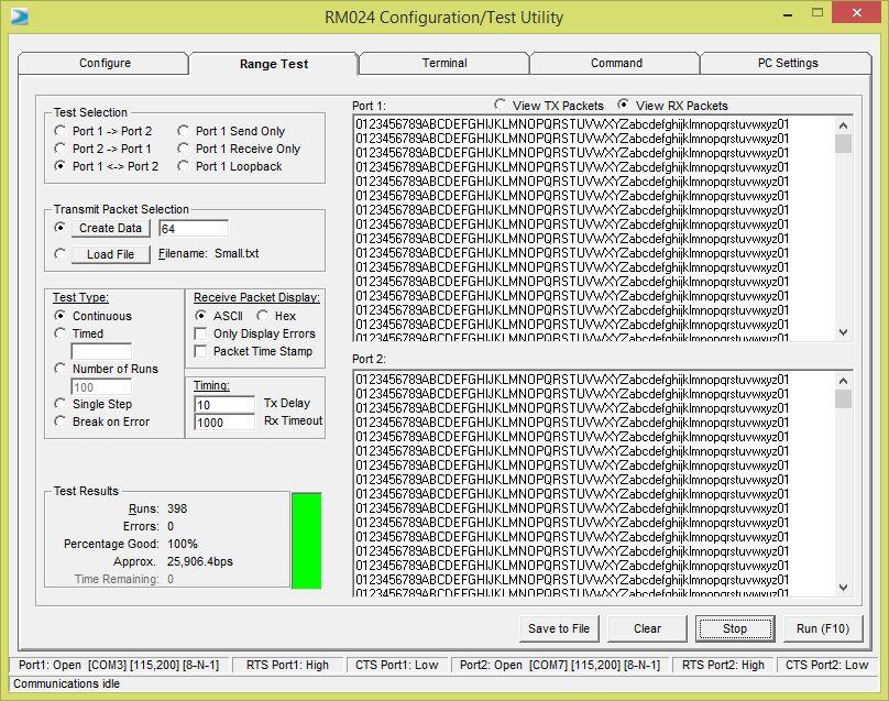
28 Wireless Transmission Data transmitted using packets Data is sent either when the packet is full, or when timeout occurs (2.5 ms) 28
29 Laird Configuration/Test Utility Free software from Laird Program and test RM024 wireless transceivers Provides option to save setups to a file Automatic configuration file version tracking 29
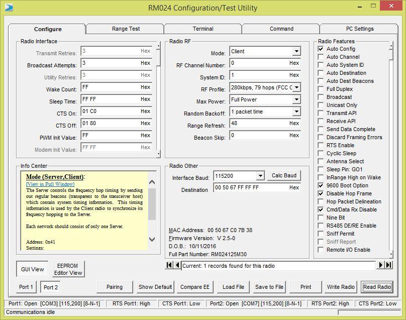
30 30
31 31
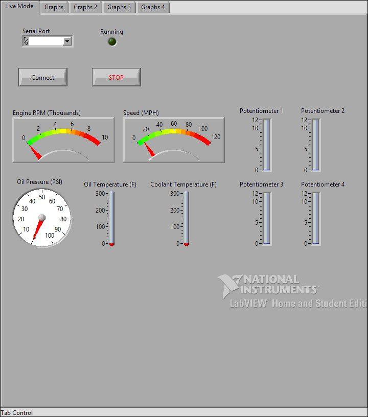
32 Track-Side Laptop LabVIEW GUI LabVIEW full version - $1000 LabVIEW Student Edition - Free No known differences between full version and student version functionality 32
33 33
34 34
35 35
36 Wireless & LabVIEW GUI Communication Instrument I/O Assistant Block LabVIEW was programmed to receive 8 unsigned 16-bit values followed by a newline Number of data bits must be a multiple of 8 LabVIEW can only handle bytes, not bits RM024 uses 8 data bits - not configurable 36

37 37
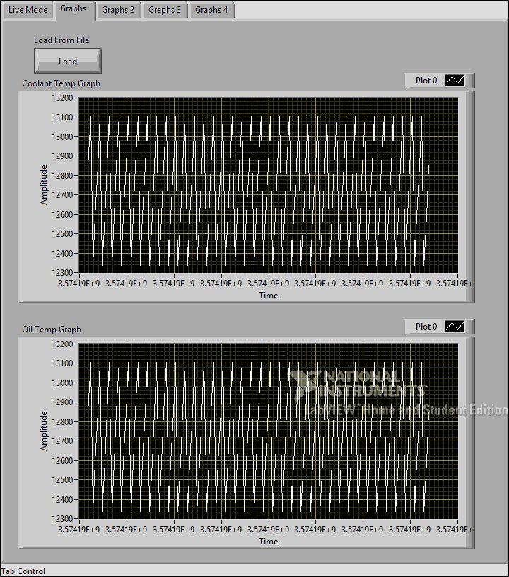
38 LabVIEW Load from File Button Code 38
 2) 3)")
39 Wireless Transmission & LabVIEW Testing 1) 2) 3) 39

40 Test Results 40
41 Test Results Wireless communication established LabVIEW receives data, displays, saves, and graphs the data 41
42 Sensors and Microcontroller Subsystem Block Diagram Subsystem Functional Requirements Sensors Microcontroller Microcontroller Function Microcontroller Programming 42

43 Subsystem Block Diagram 43
44 Subsystem Functional Requirements Sensor data input to microcontroller Data converted to proper format for output Sensor data output to RM024 transceiver and IQAN display EIA-232 data is sent to RM024 CAN data is sent to IQAN 44
45 Sensors Total of eight sensors going to the microcontroller Current outputs: Voltage outputs: RPM Sensor AiM X05SNVS00 Engine Coolant Temperature Sensor Prosense TTD25N F-H Engine Oil Temperature Sensor Prosense TTD25N F-H Engine Oil Pressure Sensor Prosense PTD H Four string potentiometers Black Diamond LX-PA Potentiometers One for each wheel Sensors will connect to the eight pins of Port F on the AT90CAN128, which serves as an A/D converter 45

46 Sensors Current-to-voltage converter circuit: 46
47 Microcontroller Microcontroller chosen was an AT90CAN128 Chosen for CAN compatibility, to communicate with the IQAN display, as well as familiarity with Atmel Embedded on DVK90CAN1 development kit, which features two 9-pin serial output ports, one EIA-232 and one CAN port 47

48 Microcontroller EIA-232 to transceiver CAN to display The board is powered by an external 9V battery power supply. The board has a switch to select regulated 3V or 5V supply to the microcontroller 48
49 Microcontroller Function AT90CAN128 will read values from sensors (those with current outputs will be conditioned with a current-to-voltage converter prior to the microcontroller ADC) AT90CAN128 includes a 10-bit ADC Convert values from sensors to data that can be read by display and transceiver 49
50 Microcontroller Programming EIA-232 Configuration Initialize with clock speed of 8MHz (system default clock speed of 8MHz and prescaler set to 16), baud rate of 9600 relates to clock before prescaler Use registers to enable serial output, 8 bit characters with no parity, 1 stop bit, and no handshaking 50
51 Microcontroller Programming CAN Configuration Using same internal clock on AT90CAN128 Set to 500 khz with prescaler of 16 to match IQAN display Microcontroller takes sensor data read from the 10-bit ADC 8 sensors generate 80 total data bits CAN frames are 8 bytes, system uses two frames One CAN frame = 64 bits, each frame holds 40 bits of sensor data One frame holds the engine sensor data, the other holds the suspension data 51
52 Messaging Spreadsheet Name AT90CAN128 Sends: Minimum Value Maximum Value Label Datatype Units/Bit Engine Coolant Temp Engine Coolant Temp Fahrenheit uint Fahrenheit uint16 1 Engine Oil Temp Engine Oil Temp Engine Oil Pressure Engine Oil Pressure PSI uint16 1 RPM RPM RPM uint16 1 Potentiometer 1 Pot value * Inch uint Potentiometer 2 Pot value * Inch uint Potentiometer 3 Pot value * Inch uint Potentiometer 4 Pot value * Inch uint
53 Summary and Conclusion Bradley SAE Formula Car Race Mechanical Engineering Department attempts to race every year System will assist Bradley SAE Formula Car Team Anticipate problems before they become serious or dangerous Safely operate formula car Improve testing capabilities before competition Log data for future reference when examining car 53
54 Summary and Conclusion Accomplishments Wireless Communication Established Fully functional track-side laptop GUI Fully functional in-car display Future Work Sensors System Testing 54
55 References

56 Appendix A - CAN Communication Source: Texas Instruments - Pg 3 56

57 Appendix B - RM024 57

58 Appendix B - RM024 58

59 Appendix B - RM024 59

60 Appendix B - RM024 60

61 Appendix B - RM024 61

62 Appendix B - RM024 62
63 Appendix B - RM024 DVK Board 63
64 Appendix B - RM024 DVK Board 64

65 Appendix B - RM024 Packets 65

66 Appendix B - RM024 Packet Header Info 66
67 Appendix C: Dipole Antennas Full-wave dipole A full-wave dipole antenna consists of two half-wavelength conductors placed end to end for a total length of approximately L = λ. The additional gain over a half-wave dipole is about 2 db, but the impedance is much higher than a half-wave dipole making it more complicated to match with ordinary, low impedance RF equipment and cabling. Half-wave dipole A half-wave dipole antenna consists of two quarter-wavelength conductors placed end to end for a total length of approximately L = λ/

68 Appendix D - Previous SAE Formula Car Teams 68
69 Appendix D - Previous SAE Formula Car Teams Both transceivers have adequate range, and can communicate using EIA-232. The RM024 is available in a development kit with everything needed for the project. The AC M does not come in a kit and requires antennas that must be ordered separately. The RM024 is cheaper, has a higher serial interface data rate, higher RF data rate, and it comes in a kit so that everything will certainly work together. 69
70 Appendix E - LabVIEW GUI Video 70

71 Appendix F - LabVIEW Graph Zoom Right-click the graph or chart and select Visible Items»Graph Palette from the shortcut menu. 71
72 Appendix F - LabVIEW Graph Zoom 6 zoom buttons Zoom to Rectangle With this option, click a point on the display you want to be the corner of the zoom area and drag the tool until the rectangle covers the zoom area. X-zoom Use this option to zoom in on an area of the graph along the x-axis. Y-zoom Use this option to zoom in on an area of the graph along the y-axis. Zoom In about Point With this option, click a point you want to zoom in on. Press and hold the <Shift> key to switch between Zoom In about Point and Zoom Out about Point. Zoom Out about Point With this option, click a point you want to zoom out from. Zoom to Fit Use this option to autoscale all x- and y-scales on the graph or chart. 72


73 Appendix G - Microcontroller Power Source 73

74 Appendix H - Sensor Characteristics AiM X05SNVS00 74
75 Appendix H - Sensor Characteristics Prosense TTD25N F-H 75

76 Appendix H - Sensor Characteristics Prosense PTD H 76

77 Appendix H - Sensor Characteristics Black Diamond LX-PA String Potentiometers 77
Lifetime Power Energy Harvesting Development Kit for Wireless Sensors User s Manual - featuring PIC MCU with extreme Low Power (XLP) Technology
 Technology") P2110-EVAL-01 Lifetime Power User s Manual - featuring PIC MCU with extreme Low Power (XLP) Technology Overview The Lifetime Power is a complete demonstration and development platform for creating battery-free
P2110-EVAL-01 Lifetime Power User s Manual - featuring PIC MCU with extreme Low Power (XLP) Technology Overview The Lifetime Power is a complete demonstration and development platform for creating battery-free
DNT24MCA DNT24MPA. Low Cost 2.4 GHz FHSS Transceiver Modules with I/O. DNT24MCA/MPA Absolute Maximum Ratings. DNT24MCA/MPA Electrical Characteristics
 - 2.4 GHz Frequency Hopping Spread Spectrum Transceivers - Direct Peer-to-peer Low Latency Communication - Transmitter RF Power Configurable - 10 or 63 mw - Built-in Chip Antenna - 250 kbps RF Data Rate
Characteristic Sym Notes Minimum Typical Maximum Units Operating Frequency Range MHz Operating Frequency Tolerance khz
 DEVELOPMENT KIT (Info Click here) 2.4 GHz ZigBee Transceiver Module Small Size, Light Weight, Low Cost Sleep Current less than 3 µa FCC and ETSI Certified for Unlicensed Operation The ZMN2405 2.4 GHz transceiver
SMARTALPHA RF TRANSCEIVER
 SMARTALPHA RF TRANSCEIVER Intelligent RF Modem Module RF Data Rates to 19200bps Up to 300 metres Range Programmable to 433, 868, or 915MHz Selectable Narrowband RF Channels Crystal Controlled RF Design
Applications. Operating Modes. Description. Part Number Description Package. Many to one. One to one Broadcast One to many
 RXQ2 - XXX GFSK MULTICHANNEL RADIO TRANSCEIVER Intelligent modem Transceiver Data Rates to 100 kbps Selectable Narrowband Channels Crystal controlled design Supply Voltage 3.3V Serial Data Interface with
Characteristic Sym Notes Minimum Typical Maximum Units Operating Frequency Range MHz. RF Chip Rate 11 Mcps RF Data Rates 1, 2, 5.
 RFM Products are now Murata products. Small Size, Light Weight, Low Cost 7.5 µa Sleep Current Supports Battery Operation Timer and Event Triggered Auto-reporting Capability Analog, Digital, Serial and
Receiver 10-5 BER -100 dbm Transmitter RF Output Power 1 10 or 63 mw mw Antenna Impedance 50 Ω
 - 2.4 GHz Frequency Hopping Spread Spectrum Transceivers - Direct Peer-to-peer Low Latency Communication - Transmitter RF Power Configurable - 10 or 63 mw - Transmitter EIRP 15.8 mw or 100 mw with 2 dbi
Characteristic Sym Notes Minimum Typical Maximum Units Operating Frequency Range MHz Operating Frequency Tolerance khz
 DEVELOPMENT KIT (Info Click here) 2.4 GHz ZigBee Transceiver Module Small Size, Light Weight, +18 dbm Transmitter Power Sleep Current less than 3 µa FCC and ETSI Certified for Unlicensed Operation The
AcuMesh Wireless RS485 Network. User's Manual SOLUTION
 AcuMesh Wireless RS485 Network User's Manual AN SOLUTION ACUMESH - WIRELESS METERING SYSTEM COPYRIGHT 2015 V1.2 This manual may not be altered or reproduced in whole or in part by any means without the
802.11g Wireless Sensor Network Modules
 RFMProducts are now Murata Products Small Size, Integral Antenna, Light Weight, Low Cost 7.5 µa Sleep Current Supports Battery Operation Timer and Event Triggered Auto-reporting Capability Analog, Digital,
DNT90MCA DNT90MPA. Low Cost 900 MHz FHSS Transceiver Modules with I/O
 - 900 MHz Frequency Hopping Spread Spectrum Transceivers - Direct Peer-to-peer Low Latency Communication - Transmitter Power Configurable to 40 or 158 mw - Built-in 0 dbi Chip Antenna - 100 kbps RF Data
DNT900. Low Cost 900 MHz FHSS Transceiver Module with I/O
 DEVELOPMENT KIT (Info Click here) 900 MHz Frequency Hopping Spread Spectrum Transceiver Point-to-point, Point-to-multipoint, Peer-to-peer and Tree-routing Networks Transmitter Power Configurable from 1
DISCONTINUED. Modulation Type Number of RF Channels 15
 RFM Products are now Murata products. 2.4 GHz Spread Spectrum Transceiver Module Small Size, Light Weight, Built-In Antenna Sleep Current less than 3 µa FCC, Canadian IC and ETSI Certified for Unlicensed
DNT2400. Low Cost 2.4 GHz FHSS Transceiver Module with I/O
 2.4 GHz Frequency Hopping Spread Spectrum Transceiver Point-to-point, Point-to-multipoint, Peer-to-peer and Tree-routing Networks Transmitter Power Configurable from 1 to 63 mw RF Data Rate Configurable
DNT90MC DNT90MP. Low Cost 900 MHz FHSS Transceiver Modules with I/O
 - 900 MHz Frequency Hopping Spread Spectrum Transceivers - Direct Peer-to-peer Low Latency Communication - Transmitter Power Configurable to 40 or 158 mw - 100 kbps RF Data Rate - Serial Port Data Rate
DISCONTINUED. Modulation Type Number of RF Channels 15
 RFM products are now Murata Products 2.4 GHz Spread Spectrum Transceiver Module Small Size, Light Weight, Low Cost Sleep Current less than 3 µa FCC, Canadian IC and ETSI Certified for Unlicensed Operation
Preliminary. RF Data Transmission Rates 38.4, 115.2, 200 and 500 kbps
 Preliminary - 2.4 GHz RS-232C, RS-485/RS-232C and USB Serial Modems - Optional 128-Bit AES Encryption - Point-to-point, Point-to-multipoint, Peer-to-peer and Tree-routing Network Capabilities - Frequency
RFID Door Unlocking System
 RFID Door Unlocking System Evan VanMersbergen Project Description ETEC 471 Professor Todd Morton December 7, 2005-1- Introduction In this age of rapid technological advancement, radio frequency (or RF)
SynthNV - Signal Generator / Power Detector Combo
 SynthNV - Signal Generator / Power Detector Combo The Windfreak SynthNV is a 34.4MHz to 4.4GHz software tunable RF signal generator controlled and powered by a PC running Windows XP, Windows 7, or Android
Tire Temperature and Pressure Monitoring System - Datasheet
 The Izze-Racing wireless Tire Temperature and Pressure Monitoring System (TTPMS) consists of small, lightweight, wheel-mounted sensors and an equally small receiver with a built in pressure transducer
Preliminary. DN-900 Series. 900 MHz Wireless Serial Modems
 Preliminary - 900 MHz RS-232C, RS-485/RS-232C and USB Serial Modems - Optional 128-Bit AES Encryption - Point-to-point, Point-to-multipoint, Peer-to-peer and Tree-routing Network Capabilities - Frequency
CL4490 HARDWARE INTEGRATION GUIDE VERSION 1.0. FCC Notice.
 CL4490 HARDWARE INTEGRATION GUIDE VERSION 1.0 wireless.support@lairdtech.com FCC Notice WARNING: This device complies with Part 15 of the FCC Rules. Operation is subject to the following two conditions:
II. LAB. * Open the LabVIEW program (Start > All Programs > National Instruments > LabVIEW 2012 > LabVIEW 2012)
") II. LAB Software Required: NI LabVIEW 2012, NI LabVIEW 4.3 Modulation Toolkit. Functions and VI (Virtual Instrument) from the LabVIEW software to be used in this lab: niusrp Open Tx Session (VI), niusrp
II. LAB Software Required: NI LabVIEW 2012, NI LabVIEW 4.3 Modulation Toolkit. Functions and VI (Virtual Instrument) from the LabVIEW software to be used in this lab: niusrp Open Tx Session (VI), niusrp
Preliminary. 4-Channel RTD/4-20 ma Wireless Sensor Node SN24R420-4
 Preliminary - 4 Analog Channel, Battery Powered Wireless Sensor Node - 2 RTD Inputs and 2 4-20 ma Inputs Plus 2 Switch Inputs - Supports 2- and 3-Wire 100 ohm Platinum RTDs - Switch State and Change-of-State
Intelligent and Flexible Monitor Circuits Detect & Record Load Profiles and Fault Events All Distribution Voltages All Conductor Types
 IQ Insulator Self-powered Line Sensor & Insulator with Wireless Communications Monitor System Performance & Reliability Load Profiling and Fault Recording & Indication Intelligent and Flexible Monitor
SPECIAL SPECIFICATION 6744 Spread Spectrum Radio
 2004 Specifications CSJ 0924-06-244 SPECIAL SPECIFICATION 6744 Spread Spectrum Radio 1. Description. Furnish and install spread spectrum radio system. 2. Materials. Supply complete manufacturer specifications
Technical Note #15. Radio Frequency Modems. GE ED&C Home Search ED&C GE ED&C Power Management Home GE ED&C PMCS Home
 1 of 5 GE ED&C Home Search ED&C GE ED&C Power Management Home GE ED&C PMCS Home GE Power Management Control System Description Software Hardware Operation Product Support Operator Interfaces F A Q s App
Specification Sym Notes Minimum Typical Maximum Units 900 MHz Operating Frequency Range MHz
 900 MHz FHSS DNT90/Ethernet Gateway Optional 128-Bit AES Encryption Point-to-point, Point-to-multipoint or Store and Forward Operation 158 mw EIRP 900 MHz Transmitter Power 10/100Base-T Auto-sensing Ethernet
BRB900 GPS Telemetry System August 2013 Version 0.06
 BRB900 GPS Telemetry System August 2013 Version 0.06 As of January 2013, a new model of the BRB900 has been introduced. The key differences are listed below. 1. U-blox GPS Chipset: The Trimble Lassen IQ
Faculty of Electrical & Electronics Engineering BEE4233 Antenna and Propagation. LAB 1: Introduction to Antenna Measurement
 Faculty of Electrical & Electronics Engineering BEE4233 Antenna and Propagation LAB 1: Introduction to Antenna Measurement Mapping CO, PO, Domain, KI : CO2,PO3,P5,CTPS5 CO1: Characterize the fundamentals
The wireless alternative to expensive cabling...
 The wireless alternative to expensive cabling... ELPRO 905U Wireless Solutions for Process Applications New Products... New Solutions The ELPRO 905U range of wireless I/O provides a low cost alternative
CDR-915 Data Radio Module INTEGRATOR S GUIDE
 CDR-915 Data Radio Module Coyote DataCom, Inc. 3941 Park Drive, Suite 20-266, El Dorado Hills, CA 95762 Tel. 916-933-9981 Fax 916-913-0951 www.coyotedatacom.com TABLE OF CONTENTS General Information and
ESE 350 Microcontroller Laboratory Lab 5: Sensor-Actuator Lab
 ESE 350 Microcontroller Laboratory Lab 5: Sensor-Actuator Lab The purpose of this lab is to learn about sensors and use the ADC module to digitize the sensor signals. You will use the digitized signals
Tyre Pressure Monitoring System Corner Recognition
 Tyre Pressure Monitoring System Corner Recognition The system consists of a set of battery powered tyre pressure fitted to wheel rims. The sensors communicate with a transceiver, fitted to each corner
2.0 Discussion: 2.1 Approach:
 2.0 Discussion: 2.1 Approach: The design for a Power Monitor and Data Logging System is comprised of two major components: the Power Meter and the Data Logger. The Power Meter is the package that plugs
DN-90 Series. 900 MHz Wireless Serial Modems
 - 900 MHz RS-232C and RS-232C/RS-485 Serial Modems - Optional 128-Bit AES Encryption - Point-to-point,Point-to-multipoint, Peer-to-peer and Store & Forward Capabilities - Frequency Hopping Spread Spectrum
SV613 USB Interface Wireless Module SV613
 USB Interface Wireless Module SV613 1. Description SV613 is highly-integrated RF module, which adopts high performance Si4432 from Silicon Labs. It comes with USB Interface. SV613 has high sensitivity
CL4790 USER GUIDE VERSION 3.0. Americas: Europe: Hong Kong:
 CL4790 USER GUIDE VERSION 3.0 Americas: +1-800-492-2320 FCC Notice WARNING: This device complies with Part 15 of the FCC Rules. Operation is subject to the following two conditions: (1) This device may
Artifex LIV 110. Laser Diode Characterization System. Engineering
 Artifex Engineering LIV 110 Laser Diode Characterization System Artifex Engineering e.k. General Manager: Dr. Steven Wright Tel: +49-(0)4921-58908-0 Dortmunder Str. 16-18 Registry number: HRA 200036 email:
Catalog
 - 1 - Catalog 1. Overview...- 3-2. Feature... - 3-3. Application...- 3-4. Block Diagram...- 3-5. Electrical Characteristics... - 4-6. Operation... - 4-1) Power on Reset... - 4-2) Sleep mode... - 4-3) Working
EVO4 Data Logger USER GUIDE
 EVO4 Data Logger USER GUIDE AiM Srl. Via Cavalcanti, 8 20063 Cernusco S/N (MI) Italia Tel. (+39) 02.9290571 Made in Italy www.aim-sportline.com EVO4 Data Logger 04 INTRODUCTION 08 GETTING STARTED 12 GENERAL
Embedded Radio Data Transceiver SV611
 Embedded Radio Data Transceiver SV611 Description SV611 is highly integrated, multi-ports radio data transceiver module. It adopts high performance Silicon Lab Si4432 RF chip. Si4432 has low reception
G3P-R232. User Manual. Release. 2.06
 G3P-R232 User Manual Release. 2.06 1 INDEX 1. RELEASE HISTORY... 3 1.1. Release 1.01... 3 1.2. Release 2.01... 3 1.3. Release 2.02... 3 1.4. Release 2.03... 3 1.5. Release 2.04... 3 1.6. Release 2.05...
DR-TRC105-EV Evaluation Kit. User s Guide
 DR-TRC105-EV Evaluation Kit User s Guide DR-TRC105-304-EV DR-TRC105-315-EV DR-TRC105-345-EV DR-TRC105-372-EV DR-TRC105-390-EV DR-TRC105-403-EV DR-TRC105-434-EV DR-TRC105-450-EV 2010-2015 by Murata Electronics
KAPPA M. Radio Modem Module. Features. Applications
 KAPPA M Radio Modem Module Features Intelligent RF modem module Serial data interface with handshake Host data rates up to 57,600 baud RF Data Rates to 115Kbps Range up to 500m Minimal external components
ACUMESH - WIRELESS RS485 NETWORK KEY FEATURES ACUMESH - WIRELESS METERING SYSTEM
 ACUMESH WIRELESS RS485 NETWORK The AcuMesh wireless metering solution is designed to connect energy meters and any devices by communicating with RS485 wirelessly. AcuMesh is a costeffective solution that
Catalog
 - 1 - Catalog 1. Overview... - 3-2. Feature...- 3-3. Application... - 3-4. Block Diagram... - 3-5. Electrical Characteristics...- 4-6. Operation...- 4-1) Power on Reset... - 4-2) Sleep mode...- 4-3) Working
Gentec-EO USA. T-RAD-USB Users Manual. T-Rad-USB Operating Instructions /15/2010 Page 1 of 24
 Gentec-EO USA T-RAD-USB Users Manual Gentec-EO USA 5825 Jean Road Center Lake Oswego, Oregon, 97035 503-697-1870 voice 503-697-0633 fax 121-201795 11/15/2010 Page 1 of 24 System Overview Welcome to the
CL4790 HARDWARE INTEGRATION GUIDE VERSION 3.0. Americas: Europe: Hong Kong:
 CL4790 HARDWARE INTEGRATION GUIDE VERSION 3.0 Americas: +1-800-492-2320 FCC Notice WARNING: This device complies with Part 15 of the FCC Rules. Operation is subject to the following two conditions: (1)
EG medlab. Three Lead ECG OEM board. Version Technical Manual. Medlab GmbH Three Lead ECG OEM Module EG01010 User Manual
 Medlab GmbH Three Lead ECG OEM Module EG01010 User Manual medlab Three Lead ECG OEM board EG01010 Technical Manual Copyright Medlab 2008-2016 Version 1.03 1 Version 1.03 28.04.2016 Medlab GmbH Three Lead
BANTAM INSTRUMENTS SOFTWARE USER S MANUAL MIL-STD-461E PRE-COMPLIANCE MEASUREMENT SYSTEM MODEL EMC-461. Model EMC-461 Software User s Manual
 BANTAM INSTRUMENTS MIL-STD-461E PRE-COMPLIANCE MEASUREMENT SYSTEM MODEL EMC-461 SOFTWARE USER S MANUAL MIL-STD-461E PRE-COMPLIANCE MEASUREMENT SYSTEM MODEL EMC-461 Software User s Manual BANTAM INSTRUMENTS
SSI-4 PLUS User Manual
 SSI-4 PLUS User Manual 1 SSI-4 PLUS... 2 1.1 Getting to Know the SSI-4 PLUS... 2 1.2 Channel Functions... 3 2 Wiring and Setup... 3 2.1 Powering the SSI-4 PLUS... 3 2.2 5V for External Sensors... 4 2.3
DragonLink Advanced Transmitter
 DragonLink Advanced Transmitter A quick introduction - to a new a world of possibilities October 29, 2015 Written by Dennis Frie Contents 1 Disclaimer and notes for early release 3 2 Introduction 4 3 The
Wireless Howto. Rev 9
 Wireless Howto Rev 9 The Overdrive System can use radio modems to communicate between the Control Computer ( CC ) and the Embedded Computer ( EC ). The modem manufacturer is Cirronet (GA, USA). The model
Index Terms IR communication; MSP430; TFDU4101; Pre setter
 Design and Development of Contactless Communication Module for Pre setter of Underwater Vehicles J.Lavanyambhika, **D.Madhavi *Digital Systems and Signal Processing in Electronics and Communication Engineering,
RF Wireless Serial Device Server
 RF-SDS RF Wireless Serial Device Server The RF-SDS subassembly is a radio transceiver acting as a Serial Device Server, which externally connects a remote serial RF transceiver to an Ethernet network (TCP/IP).
Preliminary Design Report. Project Title: Search and Destroy
 EEL 494 Electrical Engineering Design (Senior Design) Preliminary Design Report 9 April 0 Project Title: Search and Destroy Team Member: Name: Robert Bethea Email: bbethea88@ufl.edu Project Abstract Name:
INTRODUCTION. What is the LSN50
 INTRODUCTION Dragino LoRa Sensor Node Dragino LoRa Sensor Node What is the LSN50 LSN50 is a Long Range LoRa Sensor Node. It is designed for outdoor use and powered by Li/SOCl2 battery for long term use
USB Port Medium Power Wireless Module SV653
 USB Port Medium Power Wireless Module SV653 Description SV653 is a high-power USB interface integrated wireless data transmission module, using high-performance Silicon Lab Si4432 RF chip. Low receiver
QUICK START GUIDE FOR DEMONSTRATION CIRCUIT BIT DIFFERENTIAL INPUT DELTA SIGMA ADC LTC DESCRIPTION
 LTC2433-1 DESCRIPTION Demonstration circuit 745 features the LTC2433-1, a 16-bit high performance Σ analog-to-digital converter (ADC). The LTC2433-1 features 0.12 LSB linearity, 0.16 LSB full-scale accuracy,
Operations Manual for RFExtender Setup
 Operations Manual for RFExtender Setup Revised December 03, 2004 TABLE OF CONTENTS INTRODUCTION...3 SYSTEM COMPONENTS...3 TRANSCEIVER MODULE SETUP...3 SINGLE LOGGER SYSTEM SETUP...5 MULTIPLE LOGGER SYSTEM
ProLink Radio. 900 MHz SDI-12 Data Radio Scienterra Limited. Version A-0x0C-1-AC 20 October 2009
 ProLink Radio 900 MHz SDI-12 Data Radio Scienterra Limited Version A-0x0C-1-AC 20 October 2009 For sales inquiries please contact: ENVCO Environmental Collective 31 Sandringham Rd Kingsland, Auckland 1024
CL024 USER S GUIDE VERSION
 CL024 USER S GUIDE VERSION 1.0 www.lairdtech.com/wireless FCC Notice WARNING: This device complies with Part 15 of the FCC Rules. Operation is subject to the following two conditions: (1) This device may
Antenna and Propagation
 Antenna and Propagation This courseware product contains scholarly and technical information and is protected by copyright laws and international treaties. No part of this publication may be reproduced
4. BK2401/BK2421 Module RF test
 4. BK2401/BK2421 Module RF test BK2401/BK2421 Module RF performance tests including transmit power (Power) Frequency (Frequency) and sensitivity (Sensitivity) test, and FCC / CE testing major FAIL in the
The wireless alternative to expensive cabling...
 The wireless alternative to expensive cabling... ELPRO 905U Wireless Solutions for Process Applications New Products... New Solutions The ELPRO 905U range of telemetry modules provide remote monitoring
Group 4. Michael Cooke David Griffen Whitney Keith
 Group 4 Michael Cooke David Griffen Whitney Keith Edward Romero (EE) (CpE) (EE) (EE/CpE) One television s audio is broadcasted within a restaurant/gymnasium leaving all other televisions muted. Customers
CONTROL MICROSYSTEMS SCADAWave Radio Transceiver. Hardware Manual
 5908 SCADAWave Radio Transceiver Hardware Manual CONTROL MICROSYSTEMS SCADA products... for the distance 48 Steacie Drive Telephone: 613-591-1943 Kanata, Ontario Facsimile: 613-591-1022 K2K 2A9 Technical
R5 RIC Quickstart R5 RIC. R5 RIC Quickstart CONTENTS. Saab TransponderTech AB. Appendices. Project designation. Document title
 Appendices 1 (10) Project designation R5 RIC Document title CONTENTS 1 Installation... 2 1.1 Connectors... 2 1.1.1 Power... 2 1.1.2 Video... 2 1.1.3 Sync... 3 1.1.4 RS232/ARP/ACP... 3 1.1.5 Radar data...
muse Capstone Course: Wireless Sensor Networks
 muse Capstone Course: Wireless Sensor Networks Experiment for WCC: Channel and Antenna Characterization Objectives 1. Get familiar with the TI CC2500 single-chip transceiver. 2. Learn how the MSP430 MCU
900 MHz. Frequency Hopping RS-485 Master/Slave auto-sensing radio interface.
 MDR210A-485 900 MHz. Frequency Hopping RS-485 Master/Slave auto-sensing radio interface. Black Box Corporation Lawrence, PA - http://www.blackbox.com - Ph 877-877-BBOX - Fax 724-746-0746 Table of Contents
TRC EV DR TRC EV DR TRC EV
 DR-TRC103-EV Evaluation Kit User s Guide DR TRC103 868 EV DR TRC103 915 EV DR TRC103 950 EV DR-TRC103-EV User s Guide (2015/04/17) Page 1 of 11 www.murata.com Introduction The DR TRC103 series evaluation
SPECIAL SPECIFICATION 6574 Low Power Wireless Modem
 2004 Specifications CSJ 1068-04-126, etc. SPECIAL SPECIFICATION 6574 Low Power Wireless Modem 1. Description. This work shall consist of furnishing and supplying a Low Power Wireless Modem at the locations
Ocean Controls KT-5221 Modbus IO Module
 Ocean Controls Modbus IO Module 8 Relay Outputs 4 Opto-Isolated Inputs 2 Analog Inputs (10 bit) 1 PWM Output (10 bit) 4 Input Counters Connections via Pluggable Screw Terminals 0-5V or 0-20mA Analog Inputs,
Real-World Range Testing By Christopher Hofmeister August, 2011
 Real-World Range Testing By Christopher Hofmeister August, 2011 Introduction Scope This paper outlines the procedure for a successful RF range test that provides quantitative data on how the RF link performs
Multi-Channel RS-232 Serial RF Transceiver
 RF-232 Multi-Channel RS-232 Serial RF Transceiver The RF-232 subassembly is a multi-channel serial radio transceiver. This device accepts and outputs standard serial data at one of three selectable data
Big Blue Mars Final Report
 Big Blue Mars Final Report Member Names Kyle Hart Dale McClure Michael McEwen Contact Information hartman1000@hotmail.com michaelmce@yahoo.com dale.mcclure@uky.edu 2006-04-02 Faculty Advisor Dr. Bill Smith
DEC-001 Installation Instructions
 DEC-001 Installation Instructions Skill Level: The installation of this assembly requires a medium level of expertise in working with modern electronic equipment. The use of appropriate tools, correct
BEYOND TOYS. Wireless sensor extension pack. Tom Frissen s
 LEGO BEYOND TOYS Wireless sensor extension pack Tom Frissen s040915 t.e.l.n.frissen@student.tue.nl December 2008 Faculty of Industrial Design Eindhoven University of Technology 1 2 TABLE OF CONTENT CLASS
Catalogue
 Catalogue 1. Overview... - 3-2. Features... - 3-3. Applications...- 3-4. Electrical Characteristics...- 4-5. Schematic... - 4-6. Speed rate correlation table...- 6-7. Pin definition...- 6-8. Accessories...-
MAXREFDES39#: POWER AMPLIFIER BIASING THROUGH MAX11300 PIXI
 System Board 5896 MAXREFDES39#: POWER AMPLIFIER BIASING THROUGH MAX11300 PIXI OVERVIEW MAXREFDES39# System Board ENLARGE+ Introduction The MAXREFDES39# power amplifier (PA) bias reference design uses the
RF4463F30 High Power wireless transceiver module
 RF4463F30 High Power wireless transceiver module 1. Description RF4463F30 adopts Silicon Lab Si4463 RF chip, which is a highly integrated wireless ISM band transceiver chip. Extremely high receive sensitivity
Low Power with Long Range RF Module DATASHEET Description
 Wireless-Tag WT-900M Low Power with Long Range RF Module DATASHEET Description WT-900M is a highly integrated low-power half-'duplex RF transceiver module embedding high-speed low-power MCU and high-performance
Accutech GP10. Wireless gauge pressure field unit
 Accutech GP10 Wireless gauge pressure field unit 1 The Accutech GP10 wireless gauge pressure field unit provides pressure data in a variety of ranges from 250 to 10000 PSIG. With its integrated and highly
LABORATORY AND FIELD INVESTIGATIONS ON XBEE MODULE AND ITS EFFECTIVENESS FOR TRANSMISSION OF SLOPE MONITORING DATA IN MINES
 LABORATORY AND FIELD INVESTIGATIONS ON XBEE MODULE AND ITS EFFECTIVENESS FOR TRANSMISSION OF SLOPE MONITORING DATA IN MINES 1 Guntha Karthik, 2 Prof.Singam Jayanthu, 3 Bhushan N Patil, and 4 R.Prashanth
Raveon Technologies Corporation iot.raveon.com
 RTK Communications with Raveon LoRa Radios August 2016 Raveon Technologies Corporation 2461 Impala Drive Carlsbad, CA 92010 USA +1-760-444-5995 Raveon Technologies Corporation www.raveon.com www.ravtrack.com
Analog & Digital I/O Wireless Bridge USERS MANUAL R02
 Analog & Digital I/O Wireless Bridge USERS MANUAL R02 Contents Overview... 3 Specifications... 3 Absolute Maximum Ratings... 3 Recommended Operating Conditions... 3 Performance... 4 Power Requirements...
Tarocco Closed Loop Motor Controller
 Contents Safety Information... 3 Overview... 4 Features... 4 SoC for Closed Loop Control... 4 Gate Driver... 5 MOSFETs in H Bridge Configuration... 5 Device Characteristics... 6 Installation... 7 Motor
XLR PRO Radio Frequency (RF) Modem. Getting Started Guide
 Modem. Getting Started Guide") XLR PRO Radio Frequency (RF) Modem Getting Started Guide XLR PRO Radio Frequency (RF) Modem Getting Started Guide 90002203 Revision Date Description A September 2014 Initial release. B March 2014 Updated
XLR PRO Radio Frequency (RF) Modem Getting Started Guide XLR PRO Radio Frequency (RF) Modem Getting Started Guide 90002203 Revision Date Description A September 2014 Initial release. B March 2014 Updated
LAB II. INTRODUCTION TO LABVIEW
 1. OBJECTIVE LAB II. INTRODUCTION TO LABVIEW In this lab, you are to gain a basic understanding of how LabView operates the lab equipment remotely. 2. OVERVIEW In the procedure of this lab, you will build
CIC ENGINEERING 345 CENTER STREET EAST PEORIA, IL PH FAX µmpis Control Software
 µmpis Control Software Overview The µmpis Control software package allows for a user to control the operation of the umpis unit with a PC. The PC and the umpis unit are connected together using a RS232
AT-XTR-7020A-4. Multi-Channel Micro Embedded Transceiver Module. Features. Typical Applications
 AT-XTR-7020A-4 Multi-Channel Micro Embedded Transceiver Module The AT-XTR-7020A-4 radio data transceiver represents a simple and economical solution to wireless data communications. The employment of an
USER'S MANUAL. Model : K
 USER'S MANUAL Model : 2000-64K TM GINA MODEL 2000-64K Overview GINA Model 2000-64K is a stand-alone, high frequency data transceiver using spread spectrum technology. GINA 2000-64K capabilities include
EE-110 Introduction to Engineering & Laboratory Experience Saeid Rahimi, Ph.D. Labs Introduction to Arduino
 EE-110 Introduction to Engineering & Laboratory Experience Saeid Rahimi, Ph.D. Labs 10-11 Introduction to Arduino In this lab we will introduce the idea of using a microcontroller as a tool for controlling
RM24100D. Introduction. Features. 2.4GHz 100mW RS232 / RS485 / RS422 DSSS Radio Modem (IEEE compliant) Operating Manual English 1.
 Operating Manual English 1.") RM24100D 2.4GHz 100mW RS232 / RS485 / RS422 DSSS Radio Modem (IEEE 802.15.4 compliant) Operating Manual English 1.09 Introduction The RM24100D radio modem acts as a wireless serial cable replacement and
RM24100D 2.4GHz 100mW RS232 / RS485 / RS422 DSSS Radio Modem (IEEE 802.15.4 compliant) Operating Manual English 1.09 Introduction The RM24100D radio modem acts as a wireless serial cable replacement and
Guardian and DL3282 Modem Interface Technical Service Application Note
 Guardian and DL3282 Modem Interface Technical Service Application Note OVERVIEW The following document is designed to provide information for the implementation of the Guardian Wireless Modem/Analog Radio
LoRa1276 Catalogue
 Catalogue 1. Overview... 3 2. Features... 3 3. Applications... 3 4. Electrical Characteristics... 4 5. Schematic... 5 6. Speed rate correlation table... 6 7. Pin definition... 6 8. Accessories... 8 9.
Midway Design Review. Sync-In December 4, 2015
 Midway Design Review Sync-In December 4, 2015 Advisor: Professor Gao 1 Sync-In Ajwad Alam, EE Amplifier Joseph Bellve, EE User Interface Levis Agaba, CSE Tx/Rx Carl Senecal, CSE Network Formation Advisor:
PC-based controller for Mechatronics System
 Course Code: MDP 454, Course Name:, Second Semester 2014 PC-based controller for Mechatronics System Mechanical System PC Controller Controller in the Mechatronics System Configuration Actuators Power
LAX016 Series Logic Analyzer User Guide
 LAX016 Series Logic Analyzer User Guide QQ: 415942827 1 Contents I Overview... 4 1 Basic knowledge... 4 2 Product series... 4 3 Technical specification... 5 II Brief introduction to JkiSuite software...