LAX016 Series Logic Analyzer User Guide
|
|
|
- Jessica Johns
- 6 years ago
- Views:
Transcription


1 LAX016 Series Logic Analyzer User Guide QQ:
2 Contents I Overview Basic knowledge Product series Technical specification... 5 II Brief introduction to JkiSuite software How to install the software Brief introduction to GUI Brief introduction to the demo function... 7 III Connect the device Connect the device to PC Connect device to system under test Multipoint grounding to increase accuracy IV Details of operations 通道设置 Channel settings Sample depth and sample rate Set trigger conditions Get the waveform Check and measure the waveform Data save and export Analyze standard protocols PWM export V Settings for standard protocols UART/RS232/ I2C SPI CAN Simple Parallel Wire DMX UNI/O User-defined protocol analyzer
3 VI FAQs Driver installation fail with the device connected to computer Identification fail or work unstably with the device connected to the computer Signal glitches appear on individual channels The actual sample time is less than expected when the depth is set to a large value 26 5 Auto update of the software fails VII contact us
.")
4 I Overview 1 Basic knowledge Logic analyzer is the instrument that collects and displays the digital signal from the devices under test. It is mainly used for timing judgement an analysis. Unlike the oscilloscope with many voltage grades, It has only two grades(logic one and Logic zero)..after the reference voltage is set, the logic analyzer could decide from the test signal that the signal above the reference voltage is logic one, and the signal below is logic zero. The digital waveform is formed with 1 and 0. Compared with the oscilloscope, when testing and measuring the digital systems like MCU, ARM, FPGA and DSP, the logic analyzer could provide better accuracy, much more data and more complicated measuring methods. For example, if you are sampling a signal with the logic analyzer, the sample rate of which is 1Mhz, and the reference voltage is set to 1.5V, the logic analyzer would compare the current voltage with 1.5V. The signal above 1.5V would be high level(logic 1), and the signal below 1.5V would be low level(logic 0). Thus we get a sample point, and then we could link all these points(logic 1 and logic 0) to get a waveform, in which the user could see and analyze the timing of the signal, logic errors and the relation between each other. The figure below shows how the logic analyzer samples the signal: 2 Product series This product series include LA1016 LA2016 LA5016: 4
5 3 Technical specification Input PWM output power supply PC software Product type LA1016 LA2016 LA5016 Total number of channels Max sample rate 100MHz 200MHz 500MHz Measurement bandwidth 20MHz 40MHz 80MHz Min pulse captured 20ns 12.5ns 6.25ns Hardware storage 1Gbits 1Gbits 512Mbits Hardware Sample depth 50M/channel 50M/ channel 32M/ channel Max compression depth 10G/ channel 10G/ channel 5G/ channel Input voltage range -50V~+50V -50V~+50V -50V~+50V Input impedance 220KΩ, 12pF 220KΩ, 12pF 220KΩ, 12pF Threshold voltage 0.8V low level 0.8V low level 1.0V low level 1.6V high level 1.6V high level 2.0V high level Number of channels Output frequency range 0.1~20MHz 0.1~20MHz 0.1~12.5MHz Min interval for frequency adjustment 10ns 10ns 8ns Min interval for pulse width adjustment 5ns 5ns 8ns Output voltage +3.3V +3.3V +3.3V Export impedance 50Ω 50Ω 50Ω Power supply port USB2.0/3.0 USB2.0/3.0 USB2.0/3.0 Standby current 130mA 150mA 300mA Maximum active current 260mA 300mA 550mA UART(RS-232/485/422) I2C SPI CAN DMX512 I2S/PCM Supported protocols Manchester 1-Wire Simple Parallel UNI/O Supported OS Windows XP Vista Windows 7/8(32bit/64bit) 5

6 II Brief introduction to JkiSuite software 1 How to install the software The software package is JkiSuiteSetup.exe. and it could be found in the attached CD, or downloaded from the link: /download?fl=jkisuitesetup.zip, Double click JkiSuiteSetup.exe to execute the installation program. The procedure is similar with the common software in windows, and there are instructions that you could follow in every step. In the last step, you should install the driver program of hardware device, and you will see the dialog as the figure below(there could be differences between different OSs). Please select Install to complete the procedure. After the install procedure is complete, a shortcut like would be created in the start menu and desktop, and then the JkiSuite software could be accessed with this shortcut. 2 Brief introduction to GUI Whe the software is started through start menu or desktop shortcut, you will get a screen similar to the figure below. It contains the tool bar, channel settings bar, waveform display window, measurement window, PWM settings window and analyzers settings window. 6


7 The software could display in English/ 简体中文. If you want to change the language, you could press the Optios button in the top right corner, and select the language. The selection would become effective after the software is restarted. 3 Brief introduction to the demo function The software could provide demo function. You can simulate the functions without the actual hardware, and you could get a good experience of the software through this function. With the example of SPI, you could press the + button on the right side of Analyzers In analyzers settings window, the SPI analyzer would be added with default configurations. Then you could set sample depth and sample rate, and the sample time would be calculated automatically by the software. After all these are done, just press the Simulate button in the tool bar and you will get simulation waveform, which is shown in the figure below. 7

8 In the figure above, channels 0-3 contain the simulated SPI signals, and the signals in other channels are random. You could zoom the waveform though the mouse, and if you click the left button without releasing, you could drag the waveform. More details are covered in following chapters. 8
9 III Connect the device 1 Connect the device to PC When the installation process is completed, the logic analyzer can be connected to PC through the attached USB cable (In case of desktop computer, use the USB port behind the tower box). Then the computer would report that new hardware has been found. In Windows XP, there would appear a driver installation dialog, and just select to install automatically. In Windows 7/8, a dialog would appear in the top right corner of the screen. Then the install process would start automatically, and we just need to wait for a while. After the installation process is completed, a new device called Jiankun Instrument-Logic Analyzer would appear in Device Manager->Universal Serial Bus. 2 Connect device to system under test Please note that the logic analyzer and the computer share the same ground, so the voltage between the GND of system under test and the CND of the computer should be zero. Especially when the system is connected to the force electricity, please make sure the isolation is made. If devices with force electricity like frequency transformer are not isolated through the isolation transformer, the system would be connected to the force electricity. And if you connect the logic analyzer to such a system, the logic analyzer even the computer would be broken. And the damage could be beyond repair, so the isolation should be made in advance. When the logic analyzer is connected with the system under test, you should first connect the GND channel to the system under test, and then connect the signal channels. There are 16 channels in the logic analyzer. It means that up to 16 digital signals could be tested simultaneously. If the number of existing signal is less than 16, the channels could be selected at will. The channel numbers of the software correspond to that of the hardware device. In addition, when measuring the signal with high speed, the measuring lines of logic analyzer should be near the signal of system under test. The cable between the logic analyzer and the system under test should not be long, because long cables would result in heavy inductive effect and signal reflection. Therefore it is recommended that in debug stage of the system some pins should be reserved on the experiment board to make the best of measurement. The connection between the logic analyzer and the system under test is shown in the figure below: 9

10 3 Multipoint grounding to increase accuracy when measuring multiple channels with high frequency signal, the signal current from all channels would flow into the system under test through GND channel, and the inductive effect of the wire in high frequency is strong, so signal current of multiple channels would overlap on GND channel, and as a result of that, the instantaneous voltage difference would be too large to result in the glitch on the waveform under test. To remove these glitches, we could take the multipoint grounding method. Normally the logic analyzer would provide several GND channels. If we connect these channels to the grounding point of the system under test, the signal current which we have mentioned would be divided into different path, and the glitch could also be removed. The multipoint grounding mainly includes: Direct connection GND channel of the logic analyzer should be connected to the GND wire of the system under test directly. Dispersed connection the GND channels should be connected to different parts of the system under test. Multiple GND channels should not be connected to one grounding point of the system. 10

11 IV Details of operations After the software installation and device connection are complete, we could sample the signal and analyze it. In this chapter we will see how to use the logic analyzer step by step. Some of these steps need to be configured only once, and in future operations we could just skip them. 1 通道设置 Channel settings There are 16 channels in the logic analyzer, and not all these channels would be in real use. Limited to the size of computer screen, when more channels need to be displayed on the screen, every channel looks even smaller, and it is not convenient to watch. After setting some parameters, the software could display the channels required, and hide other unused channels. We can make it done in this way: Press the down arrow on the right side of the channel label, and select Hide or Show to hide or show the channel. As shown in the figure below, the settings could be used for this channel, all channels above this channel and all channels below this channel. In addition, current channel could be moved up and down through the Move menu. Reset menu will restore the channels to default settings and labels, and Options menu could hide or show the trigger button bar and channel label bar. 2 Sample depth and sample rate Sample depth is the number of sample points. It determines how much data the logic analyzer could sample at a time. And it is apparent that the larger sample depth is, the more data it could sample. Sample rate, the frequency to sample the signal, is the number of sample point per second. It determines the time accuracy of sample result. Larger sample rate results in better accuracy. The sample period represents the time accuracy of sample result. The time one sampling process could last equals to sample depth sample rate. Before sampling, we could first estimate the signal to test about the maximum frequency, the data required, etc. Then we could select the sample rate based on the maximum frequency, and we might follow the following rule: Sample rate should be 5 times more than the signal to test, 11


12 and 10 times would be better. However, it is not a good idea to have a too large sample rate, because with the same sample depth, large sample rate means short sample time. Therefore, sample rate and sample time are two factors we should consider. In real applications, the parameters should be slightly more than the minimum requirement. The settings of sample depth and sample rate are shown in the figure below: 3 Set trigger conditions In the example above, the logic analyzer could sample signal of 640ms with 32M sample depth and 50M sample rate. The trigger is not set by default, and if we press start button, the logic analyzer would start to sample. It would stop automatically in 640ms, and display the waveform in the screen. But in real environment, the signal may not be continuous, and the user can not tell when it would occur, such as UART communication. In this way, maybe we could not sample any effective data during the time since we pressed start. To solve this problem, we could utilize the trigger function. First we set a certain condition, and then when the signal meets the condition, the data sample would start. This is how trigger works, and the conditions here are trigger conditions, such as jump edge of the signal, high/low level or the combinations of them. The trigger conditions should be set based on the characteristics of the signal to test, for example, in UART communication, for the idle state in which no data are transferred, the signal is high level, and every UART data frame is started by the transfer from idle state to start bit, which is low level, so we should set the falling edge of this channel as the trigger condition. If the channel 0 is used for UART signal, we just need to press the falling edge button on the right side of channel 0. 12


13 After the trigger is set and the button start is pressed again, if the trigger condition (falling edge) we have set have not appeared on channel 0, the logic analyzer would stay in wait state until the falling edge arrives. Then the device will sample and save the data, and upload the data to the computer for displaying and analyzing when the process is complete. Except the edge and level trigger condition for single channel, the logic analyzer also supports the condition combinations of multiple channels, such as levels, one edge and multiple levels. The final condition is the logical AND of these conditions, which means the sampling process starts when all conditions are met. In this way, the trigger can be the result of certain parallel data. It could be used in the situation when the master device like MCU accesses the peripheral through the bus and we want to check the data write/read operations of a certain address. For example, if we want to check the data operations of address 0x35, channels 0-7 should be connected to 8 address lines, and the other channels are connected to the data lines. After we set the level combination of channel 0-7 as the trigger condition, the data in this address could be sampled. The trigger settings are: 4 Get the waveform The sampling process is started by pressing the start button. The logic analyzer samples the signal since then (trigger conditions should be met if they are set), and stops if it has got the sample points (sample depth) required. It would upload the data to the computer. The software would restore the waveform and maybe measures or analyzes the data later. 13


14 5 Check and measure the waveform After the sampling process is complete, the waveform would be displayed in the screen. From this figure, we can see the coordinate values of the time axis are too large, and the effective waveform is within a very short period. You can click the left button of the mouse to zoom out the waveform; while the right button would zoom it in. And you can get these done with the mouse wheel too. After the waveform is zoomed up, you could s ee: From the measurement window, we can see the relative data of current waveform. And all the measurement items could be turned on or off by pressing the circle on the right side of the measurement window. After the measurement items required are set, if you move the mouse to the waveform window, the software would measure the relative data of the position where the cursor stays, and display them in the measurement window. 14


15 For example, if the cursor is located in the low pulse of channel 2, an arrow would appear in the high pulse next to this pulse. And at the same time, the relative measurement information would appear in the measurement window on the right side. Pulse width which is 28ns refers to the low level pulse, and the period is result of low level + next high level, which is 56ns. The duty cycle is 50%, and the frequency is 17.86MHz. The byte is a 16-bit data which is the combination of value in channel When we press the T1 and T2 in the measurement window, a vertical green line which is called time marker would appear. If we press T1 and put the marker on the rising edge of channel 1, then we press T2 and put the marker on the falling edge of channel 1, the time corresponding to T1 and T2 would appear on the right side, and the absolute value of time difference between T1 and T2 would also be calculated. In addition, there is another time marker T3, which can be turned on through the options menu of measurement window, and provide more information. 6 Data save and export The data sampled could be saved into the hard disk of the computer for future check and comparison. Data saving can be handled through the menu options->save data on the top right corner of software interface. You just need to specify the file path and file name to save. If you need to check the data saved before, just use the menu options->open. Instead of the sample data, the menu save settings only saves the configuration data. Export data could export sample data in the format of txt, bin and csv, and they could be used in other software like MATLAB, Excel. 15
, besides displaying the waveform and some measurement data, the software could analyze the data to get the specific data according to protocol specifications.")
. When this is done, the SPI analyzer would be added.")
16 7 Analyze standard protocols If the signal to test conforms to standard protocols like UART, I2C, SPI which are supported by JkiSuite software(the complete protocol list is in section Product technical specification ), besides displaying the waveform and some measurement data, the software could analyze the data to get the specific data according to protocol specifications. For example, channels 0-3 are used for the standard 4-wire SPI signal. You can press the + button on the right side of the analyzers window and select SPI in the dialog. In this dialog, the actual parameter of SPI should be set (Please check section Standard protocol set for more details). When this is done, the SPI analyzer would be added. Then the software would analyze the data of channels 0-3 according to standard SPI timing specification, and display the result on channel MOSI and channel MISO. The data is displayed in hexadecimal by default. If you want to change the format, please press the button which looks like a circle in the analyzer bar, and select the format required in the menu. 16


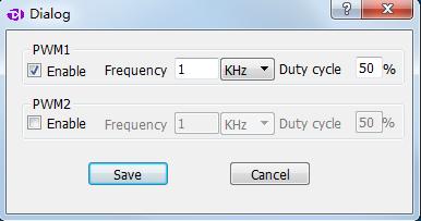
17 The analyzed data could be exported as txt or csv through export menu, and they could be used in other software. If you want to change the configuration of SPI analyzer, the menu edit could provide help. button on the left could remove the analyzer. The figure below shows the exported data of UART, I2C and SPI, and we can see the result contains time value, data packet number and the analyzed data. 8 PWM export There are two PWM waveform generators in the logic analyzer, and they can generate square wave whose duty cycle could be adjusted. By default, PWM1 is turned on, and outputs 1KHz square wave with 50% duty cycle; while PWM2 is turned off, and outputs low level. As is shown in the figure below, the PWM settings could be change through the menu button on the right side of PWM settings window. In this dialog, the PWM channel could be turned off through Enable box. If it is turned on, we could edit the frequency and duty cycle. After the settings are complete, just press the save button, and the software will generate the PWM signal with the new configuration. 17
18 18

19 V Settings for standard protocols 1 UART/RS232/485 For standard UART, RS232 and RS485, they have the same timing definitions of the physical layer, so they share the same analyzer, and the figure below shows the setting dialog of UART/RS232/485 analyzer. 1 st item, select the channel to use. 2 nd item, set the baud rate, and the baud rate here should match that in actual use. 3 rd item, use the auto baud, and the software could identify the baud rate automatically. In case of the baud rate is unknown, this option should be enabled. But the accuracy of automatic identification depends on actual signal, and the result could be incorrect. 4 th item, select the number of data bits, and it is 8 most of the time. 5 th item, select the number of stop bits, and there are 3 options: 1, 1.5 and 2. 6 th item, set the parity bit, and there are 3 options: no parity, even parity and odd parity.. 7 th item, set the bit order in data transfer, and the options could be LSB(Least Significant Bit Sent First) and MSB(Most Significant Bit Sent First). 8 th item, invert the data or not. Normally Inverted is only used for RS232(As For RS232, positive level is 0 and negative level is 1) and Non Inverted could used for UART and RS th item, set bit 9 as address flag in multiple machine communication or not, and by default, None. When this mode is actually used (seldom used, note that it is different with RS485 multiple machine communication), it could be used for address byte flag. Please note that if the signal under test is differential signal like RS485 and RS232, there are 3 ways to connect the wire: 1 The GND channel of the logic analyzer is connected to the GND of the test system, and 2 signal channels are connected to RXD and TXD pins of the level shift chip respectively. 19

20 2 The GND channel of the logic analyzer is connected to the GND of the test system, and 1 signal channel is connected to the A end of the RS485 bus. 3 Connect the RS485 bus to a module that transfer RS485 to TTL, and the GND and a signal channel of the logic analyzer are connected to the GND and signal export end of the system under test. Most of the time, all these 3 ways could be used to sample the signal, but according to RS485 specification, the voltage which the AB ends could identify is between 0.2~6V. In complicated situations, such as master with many slaves or long wire, the difference of the bus end could be too little, and the logic analyzer could not identify the signal level correctly with method 2. So method 1 and method 3 are recommended if conditions permit. 2 I2C The setting dialog of I2C analyzer is shown below: 1 st item, the channel used for SDA signal (data) 2 nd item, the channel used for SCL signal (clock) 3 rd item, the way to display the address byte. For I2C protocol, every communication is started with addressing operation, and this byte contains 1-bit read/write flag and device address which is 7-bit wide. And there are three options to display: to display as a whole (8-bit, read/write bit included); to display as a whole but the read/write flag is 0(8-bit, read/write bit set as 0); only display 7-bit address (7-bit, address bits only). 3 SPI The setting dialog of SPI analyzer is shown below: 20
 5 th item, transmission mode of data bits: MSB(Most Significant Bit First) or LSB(Least Significant Bit First), usually MSB.")
21 1 st item, the channel for MOSI signal(master out slave in) 2 nd item, the channel for MISO signal(master in slave out) 3 rd item, the channel for CLOCK signal(clock) 4 th item, the channel for ENABLE signal(enable) 5 th item, transmission mode of data bits: MSB(Most Significant Bit First) or LSB(Least Significant Bit First), usually MSB. 6 th item, data length for one transfer, usually 8 or 16 bits. 7 th item, idle state of the clock. CPOL = 0: the clock wire remains low in idle state. CPOL = 1: the clock wire remains high in idle state. 8 th item, the edge in which data is latched. CPHA=0: data latched in last clock edge. CPHA=1: data latched in next clock edge. 9 th item, the active level of enable signal: active low(enable line is Active Low) or active high(enable line is Active High). 4 CAN The setting dialog of CAN analyzer is shown below: 1 st item, the channel to use. 2 nd item, baud rate in communication. 21

22 Please note that the signal from CAN bus is differential, there are 3 ways to measure CAN signal: 1 The GND channel of the logic analyzer is connected to the GND of the test system, and 2 signal channels are connected to RXD and TXD pins of the level shift chip respectively. 2 The GND channel of the logic analyzer is connected to the L end of CAN bus, and 1 signal channel is connected to the H end of CAN bus. 3 Connect the CAN bus to a module that transfer CAN to TTL, and the GND and a signal channel of the logic analyzer are connected to the GND and signal export end of the system under test. Most of the time, all these 3 ways could be used to sample the signal, but according to CAN specification, the voltage between the H-L ends is 0V and 2V. In complicated situations, such as master with many slaves or long wire, the difference of the bus end could be too little, and the logic analyzer could not identify the signal level correctly with method 2. In addition, the GND channel of method 2 need to be connected to the CAN-L end, but if other signals need to be tested at the same time, the grounding could be confusing. So method 1 and method 3 are recommended if conditions permit. 5 Simple Parallel The setting dialog of simple parallel analyzer is shown below: 1 st ~8 th item, the channel used for data bus. 9 th item. the channel used for clock signal of data latch. 10 th item, data latch on the rising edge(data is valid on Clock rising edge) of clock signal or falling edge(data is valid on Clock falling edge). 22

23 6 1-Wire The setting dialog of 1-Wire analyzer is shown below: 1 st item, the channel to use. 7 DMX-512 The setting dialog of DMX-512 analyzer is shown below: 1 st item, the channel to use. 2 nd item, accecpt DMX us MAB signal or not. 8 UNI/O The setting dialog of UNI/Oanalyzer is shown below 1 st item, the channel to use. 23
24 9 User-defined protocol analyzer Besides the standard protocol analyzers in the software, the API functions provided by the software allow users develop their own analyzers. The software API and user manual could be downloaded from the link below: /download?fl=jkianalyzersdk.zip 24
25 VI FAQs 1 Driver installation fail with the device connected to computer First, JkiSuite should have been installed before connecting the device to computer. If the software has not been installed, the OS could not find the driver, so the installation would fail. And it would be a good idea to install the software without the hardware connected to the computer. Second, the device driver is installed automatically by installation program during installing process. If the driver installation is blocked unintentionally during installation process, or it is not installed correctly due to other reasons, when you connect the device for the first time, the driver installation would fail too. In this case, you can find the unknown hardware devices in the device manager, click the right button to install the driver program again. Please select manual installation. The driver program is located in installation directory\drivers, and select the right directory based on your operating system. 2 Identification fail or work unstably with the device connected to the computer When the logic analyzer works at full speed, there would be a lot of the current consumed (maybe more than 500mA). So if the USB port of the computer can not supply sufficient power, the device could be identified incorrectly or work unstably. To solve this, the laptop users could try to switch to the USB port on the other side, and the desktop users must use the USB port behind the tower box. If the USB-HUB is being used, please connect the device USB port directly. 3 Signal glitches appear on individual channels There are two cases when signal glitches appear: the unused channels are floating, or several signals with high speed are sampled simultaneously. It is normal that the glitch appears on unused channels, this is because the floating channel wire is like an antenna, and it will transmit weak and alternating signal, and this would result in glitches. We could hide such channels, or keep them and the signal channels at a longer distance. And we should check the grounding of the logic analyzer and the system under test. And for the glitches which appear when measuring multiple channels with high speed, the reason for that has been explained in the section Multipoint grounding to increase accuracy, and the method to handle this is multipoint grounding 25
26 4 The actual sample time is less than expected when the depth is set to a large value The logic analyzer is designed with a large-sized memory, to store the sample data temporarily. And through compression algorithm the depth is further extended. With this compression algorithm, the current and last sample data would be compared, if they are not the same, a new sample data would be generated; otherwise, only the count for last state would be incremented and no new sample data would be generated. And as a result of this, if the signal is discontinuous (for most communication system) or change slowly, the sample depth would be extended greatly. However, if the signal change rapidly the extension effect would not be so obvious. This is why the sample time is less than expected when the sample depth is set above 100M (all the depth items with *) and the signal changes rapidly. 5 Auto update of the software fails The software supports auto update, when a new version is released, a message would tell the user to update. However, because of system permission and security policy of the operating system, the auto update could fail. It this happens, the user could download the software from our website, and after uninstalling the software, the user could install the new version. /download?fl=jkisuitesetup.zip 26
27 VII contact us Thanks for choosing our product, if you have any questions, please contact us in the following ways, and we will serve you wholeheartedly. Tel: Web: QQ:
Page 1/10 Digilent Analog Discovery (DAD) Tutorial 6-Aug-15. Figure 2: DAD pin configuration
 Tutorial 6-Aug-15. Figure 2: DAD pin configuration") Page 1/10 Digilent Analog Discovery (DAD) Tutorial 6-Aug-15 INTRODUCTION The Diligent Analog Discovery (DAD) allows you to design and test both analog and digital circuits. It can produce, measure and
Page 1/10 Digilent Analog Discovery (DAD) Tutorial 6-Aug-15 INTRODUCTION The Diligent Analog Discovery (DAD) allows you to design and test both analog and digital circuits. It can produce, measure and
RIGOL. User s Guide. DS6000 Digital Oscilloscope Demo Board. July RIGOL Technologies, Inc.
 RIGOL User s Guide DS6000 Digital Oscilloscope Demo Board July 2011 RIGOL Technologies, Inc. RIGOL Guaranty and Declaration Copyright 2011 RIGOL Technologies, Inc. All Rights Reserved. Trademark Information
EVDP610 IXDP610 Digital PWM Controller IC Evaluation Board
 IXDP610 Digital PWM Controller IC Evaluation Board General Description The IXDP610 Digital Pulse Width Modulator (DPWM) is a programmable CMOS LSI device, which accepts digital pulse width data from a
Debugging a Boundary-Scan I 2 C Script Test with the BusPro - I and I2C Exerciser Software: A Case Study
 Debugging a Boundary-Scan I 2 C Script Test with the BusPro - I and I2C Exerciser Software: A Case Study Overview When developing and debugging I 2 C based hardware and software, it is extremely helpful
MICROWAVE FREQUENCY SYNTHESIZER QP-FSPLL USER MANUAL
 MICROWAVE FREQUENCY SYNTHESIZER QP-FSPLL-0040-01 USER MANUAL The QP-FSPLL-0040-01 is a low-phase noise wideband synthesizer operating from 50 MHz to 40 GHz with a nominal output power of +15 dbm. The synthesizer
Lab 1.2 Joystick Interface
 Lab 1.2 Joystick Interface Lab 1.0 + 1.1 PWM Software/Hardware Design (recap) The previous labs in the 1.x series put you through the following progression: Lab 1.0 You learnt some theory behind how one
Catalog
 - 1 - Catalog 1. Overview... - 3-2. Feature...- 3-3. Application... - 3-4. Block Diagram... - 3-5. Electrical Characteristics...- 4-6. Operation...- 4-1) Power on Reset... - 4-2) Sleep mode...- 4-3) Working
E31-TTL-500 Datasheet V Feature E31-TTL-500
 E31-TTL-500 Datasheet V1.0.1.Introduction E31-TTL-500 1.1 Feature E31-TTL-500 E31-TTL-500 is a 500mW wireless transceiver module with narrow-band transmission, operates at 425-450.5MHz (default: 433MHz),
User manuel. Hybrid stepper servo drive
 User manuel Hybrid stepper servo drive 1 Overview Hybridstepper servo drive system integrated servo control technology into the digital step driver. It adopts typical tricyclic control method which include
Low Power with Long Range RF Module DATASHEET Description
 Wireless-Tag WT-900M Low Power with Long Range RF Module DATASHEET Description WT-900M is a highly integrated low-power half-'duplex RF transceiver module embedding high-speed low-power MCU and high-performance
MADEinUSA OPERATOR S MANUAL. RS232 Interface Rev. A
 MADEinUSA OPERATOR S MANUAL RS232 Interface 92-3006 Rev. A www.iradion.com Iradion Laser, Inc. 51 Industrial Dr. N. Smithfield, RI 02896 (410) 762-5100 Table of Contents 1. Overview... 2 2. Equipment Required...
USB Multifunction Arbitrary Waveform Generator AWG2300. User Guide
 USB Multifunction Arbitrary Waveform Generator AWG2300 User Guide Contents Safety information... 3 About this guide... 4 AWG2300 specifications... 5 Chapter 1. Product introduction 1 1. Package contents......
CMOS Serial Digital Pulse Width Modulator INPUT CLK MODULATOR LOGIC PWM 8 STAGE RIPPLE COUNTER RESET LOAD FREQUENCY DATA REGISTER
 css Custom Silicon Solutions, Inc. S68HC68W1 May 2003 CMOS Serial Digital Pulse Width Modulator Features Direct Replacement for Intersil CDP68HC68W1 Pinout PDIP / SOIC (Note #1) TOP VIEW Programmable Frequency
LC-10 Chipless TagReader v 2.0 August 2006
 LC-10 Chipless TagReader v 2.0 August 2006 The LC-10 is a portable instrument that connects to the USB port of any computer. The LC-10 operates in the frequency range of 1-50 MHz, and is designed to detect
MSO Supplied with a full SDK including example programs Software compatible with Windows XP, Windows Vista and Windows 7 Free Technical Support
 PicoScope 2205 MSO USB-POWERED MIXED SIGNAL OSCILLOSCOPE Think logically... 25 MHz analog bandwidth 100 MHz max. digital input frequency 200 MS/s mixed signal sampling Advanced digital triggers SDK and
SV613 USB Interface Wireless Module SV613
 USB Interface Wireless Module SV613 1. Description SV613 is highly-integrated RF module, which adopts high performance Si4432 from Silicon Labs. It comes with USB Interface. SV613 has high sensitivity
CMOS Serial Digital Pulse Width Modulator INPUT CLK MODULATOR LOGIC PWM 8 STAGE RIPPLE COUNTER RESET LOAD FREQUENCY DATA REGISTER
 css Custom Silicon Solutions, Inc. S68HC68W1 April 2003 CMOS Serial Digital Pulse Width Modulator Features Direct Replacement for Intersil CDP68HC68W1 Pinout (PDIP) TOP VIEW Programmable Frequency and
SonoLab Echo-I User Manual
 SonoLab Echo-I User Manual Overview: SonoLab Echo-I is a single board digital ultrasound pulse-echo solution. The system has a built in 50 volt high voltage generation circuit, a bipolar pulser, a transmit/receive
µchameleon 2 User s Manual
 µchameleon 2 Firmware Rev 4.0 Copyright 2006-2011 Starting Point Systems. - Page 1 - firmware rev 4.0 1. General overview...4 1.1. Features summary... 4 1.2. USB CDC communication drivers... 4 1.3. Command
RF1212 RF1212 Ultra-low Power ISM Transceiver Module V2.0
 RF1212 Ultra-low Power ISM Transceiver Module V2.0 Application: Features: Home automation Security alarm Telemetry Automatic meter reading Contactless access Wireless data logger Remote motor control Wireless
MD04-24Volt 20Amp H Bridge Motor Drive
 MD04-24Volt 20Amp H Bridge Motor Drive Overview The MD04 is a medium power motor driver, designed to supply power beyond that of any of the low power single chip H-Bridges that exist. Main features are
DRF5150S Wireless Sensor Transmitter Module V1.30
 DRF5150S Wireless Sensor Transmitter Module V1.30 Features GFSK Transmitter module ISM frequency bands 81K bps data rate 10dBm output power Baud rate configurable 256 bytes data buffer Standby current
Analog Arts SF990 SF880 SF830 Product Specifications
 1 www.analogarts.com Analog Arts SF990 SF880 SF830 Product Specifications Analog Arts reserves the right to change, modify, add or delete portions of any one of its specifications at any time, without
Analog Arts SL987 SL957 SL937 SL917 Product Specifications [1]
![Analog Arts SL987 SL957 SL937 SL917 Product Specifications [1]](/thumbs/95/126095980.jpg "Analog Arts SL987 SL957 SL937 SL917 Product Specifications [1]") www.analogarts.com Analog Arts SL987 SL957 SL937 SL917 Product Specifications [1] 1. These models include: an oscilloscope, a spectrum analyzer, a data recorder, a frequency & phase meter, an arbitrary
www.analogarts.com Analog Arts SL987 SL957 SL937 SL917 Product Specifications [1] 1. These models include: an oscilloscope, a spectrum analyzer, a data recorder, a frequency & phase meter, an arbitrary
Roland Kammerer. 13. October 2010
 Peripherals Roland Institute of Computer Engineering Vienna University of Technology 13. October 2010 Overview 1. Analog/Digital Converter (ADC) 2. Pulse Width Modulation (PWM) 3. Serial Peripheral Interface
BANTAM INSTRUMENTS SOFTWARE USER S MANUAL MIL-STD-461E PRE-COMPLIANCE MEASUREMENT SYSTEM MODEL EMC-461. Model EMC-461 Software User s Manual
 BANTAM INSTRUMENTS MIL-STD-461E PRE-COMPLIANCE MEASUREMENT SYSTEM MODEL EMC-461 SOFTWARE USER S MANUAL MIL-STD-461E PRE-COMPLIANCE MEASUREMENT SYSTEM MODEL EMC-461 Software User s Manual BANTAM INSTRUMENTS
Analog Devices Welcomes Hittite Microwave Corporation NO CONTENT ON THE ATTACHED DOCUMENT HAS CHANGED
 Analog Devices Welcomes Hittite Microwave Corporation NO CONTENT ON THE ATTACHED DOCUMENT HAS CHANGED www.analog.com www.hittite.com THIS PAGE INTENTIONALLY LEFT BLANK HMC6383 Evaluation Kit Analog, Digital
MAX11300PMB1 Peripheral Module and Munich (USB2PMB1) Adapter Board Quick Start Guide
 Adapter Board Quick Start Guide") MAX11300PMB1 Peripheral Module and Munich (USB2PMB1) Adapter Board Quick Start Guide Rev 0; 7/14 For pricing, delivery, and ordering information, please contact Maxim Direct at 1-888-629-4642, or visit
MAX11300PMB1 Peripheral Module and Munich (USB2PMB1) Adapter Board Quick Start Guide Rev 0; 7/14 For pricing, delivery, and ordering information, please contact Maxim Direct at 1-888-629-4642, or visit
Embedded Radio Data Transceiver SV611
 Embedded Radio Data Transceiver SV611 Description SV611 is highly integrated, multi-ports radio data transceiver module. It adopts high performance Silicon Lab Si4432 RF chip. Si4432 has low reception
User s Guide. DDS-3005 USB Operation Manual
 User s Guide DDS-3005 USB Operation Manual Table of Contents Chapter 1 Introduction...1 1.1 Introduction...1 1.2 Working Principle...1 1.3 Hardware Specification...1 Chapter 2 Installation...3 2.1 System
RIGOL Data Sheet. DG3000 Series Function/Arbitrary Waveform Generator DG3121A, DG3101A, DG3061A. Product Overview. Easy to Use Design.
 RIGOL Data Sheet DG3000 Series Function/Arbitrary Waveform Generator DG3121A, DG3101A, DG3061A Product Overview DG3000 Series Function/Arbitrary Waveform Generators adopt DDS technology, which enables
RS-232 Electrical Specifications and a Typical Connection
 Maxim > Design Support > Technical Documents > Tutorials > Interface Circuits > APP 723 Keywords: RS-232, rs232, RS-422, rs422, RS-485, rs485, RS-232 port powered, RS-232 to RS-485 conversion, daisy chain,
Purchase the sample: E51-TTL-500 Datasheet V Feature E51-TTL-500
 E51-TTL-500 Datasheet V1.0.1.Introduction E51-TTL-500 1.1 Feature E51-TTL-500 E51-TTL-500 is a 500mW wireless transceiver module(uart), with transparent transmission, operates at 225-237.6MHz z(default
Introduction to Lab Instruments
 ECE316, Experiment 00, 2017 Communications Lab, University of Toronto Introduction to Lab Instruments Bruno Korst - bkf@comm.utoronto.ca Abstract This experiment will review the use of three lab instruments
SC16A SERVO CONTROLLER
 SC16A SERVO CONTROLLER User s Manual V2.0 September 2008 Information contained in this publication regarding device applications and the like is intended through suggestion only and may be superseded by
Catalog
 - 1 - Catalog 1. Description...- 3-2. Features...- 3-3. Applications... - 3-4. Block Diagram...- 3-5. Electrical Characteristics... - 5-6. Operation... - 5 - Power on Reset... - 5 - Working mode... - 6
SV-MESH Mesh network series Catalogue
 Catalogue 1. Description... 3 2. Features... 3 3. Applications... 3 4. Block Diagram... 4 5. Electrical Characteristics... 5 6. Operation... 5 Power on Reset... 5 Working mode... 6 Router mode... 8 Setting
USER GUIDE. Piezo Motor with Encoder. Installation & Software Control Guide. (For Piezo Motor Model LPM-2M, LPM-5, PM-1124R)
") www.dtimotors.com USER GUIDE Piezo Motor with Encoder Installation & Software Control Guide (For Piezo Motor Model LPM-2M, LPM-5, PM-1124R) Version 05312018v11 Page 0 Table of Contents 1.0 Introduction...
www.dtimotors.com USER GUIDE Piezo Motor with Encoder Installation & Software Control Guide (For Piezo Motor Model LPM-2M, LPM-5, PM-1124R) Version 05312018v11 Page 0 Table of Contents 1.0 Introduction...
Citrus Circuits Fall Workshop Series. Roborio and Sensors. Paul Ngo and Ellie Hass
 Citrus Circuits Fall Workshop Series Roborio and Sensors Paul Ngo and Ellie Hass Introduction to Sensors Sensor: a device that detects or measures a physical property and records, indicates, or otherwise
Quick Start Guide for the PULSE PROFILING APPLICATION
 Quick Start Guide for the PULSE PROFILING APPLICATION MODEL LB480A Revision: Preliminary 02/05/09 1 1. Introduction This document provides information to install and quickly start using your PowerSensor+.
DASL 120 Introduction to Microcontrollers
 DASL 120 Introduction to Microcontrollers Lecture 2 Introduction to 8-bit Microcontrollers Introduction to 8-bit Microcontrollers Introduction to 8-bit Microcontrollers Introduction to Atmel Atmega328
EG medlab. Three Lead ECG OEM board. Version Technical Manual. Medlab GmbH Three Lead ECG OEM Module EG01010 User Manual
 Medlab GmbH Three Lead ECG OEM Module EG01010 User Manual medlab Three Lead ECG OEM board EG01010 Technical Manual Copyright Medlab 2008-2016 Version 1.03 1 Version 1.03 28.04.2016 Medlab GmbH Three Lead
RF7129 Ultra-low power Tranceiver module V2.0
 1. General RF7129 series is a low cost, ultra-low power, high performance transparent two way semi-duplex GFSK transceiver with operation at 433/470/868/915 Mhz. It integrates with high speed MCU from
User s Manual. Hantek1025G ARBITRARY FUNCTION GENERATOR
 User s Manual Hantek1025G ARBITRARY FUNCTION GENERATOR www.hantek.com Content General safety summary... 1 Introduction... 2 Chapter 1 Getting started... 3 1.1 System Requirements... 4 1.2 Installing Hardware...
Wave Inspector Navigation and Search: Simplifying Waveform Analysis
 Wave Inspector Navigation and Search: Simplifying Waveform Analysis Our thanks to Tektronix for allowing us to reprint the following article. Introduction As Moore s Law pushes electronic technology faster,
ZKit-51-RD2, 8051 Development Kit
 ZKit-51-RD2, 8051 Development Kit User Manual 1.1, June 2011 This work is licensed under the Creative Commons Attribution-Share Alike 2.5 India License. To view a copy of this license, visit http://creativecommons.org/licenses/by-sa/2.5/in/
DRF4432D20 20dBm ISM RF Transceiver Module V1.21
 DRF4432D dbm ISM RF Transceiver Module V1.21 Features GFSK transceiver Module ISM frequency bands 19.2K bps data rate Multiple channels dbm Max. output power Baud rate configurable 256 bytes data buffer
Catalogue
 - 1 - Catalogue 1. Description... - 3-2. Features... - 3-3. Applications...- 3-4. Block Diagram... - 3-5. Electrical Characteristics...- 4-6. Operation...- 5 - Power on Reset... - 5 - Working mode... -
2F. No.25, Industry E. 9 th Rd., Science-Based Industrial Park, Hsinchu, Taiwan Application Note of OGM220, AN001 V1.8
 Application Note of OGM220, AN001 V1.8 1.0 Introduction OGM220 series is a dual channels NDIR module having a digital output directly proportional to CO2 concentration. OGM220 is designed for multi-dropped
16 Channels LED Driver
 16 Channels LED Driver Description The SN3216 is a fun light LED controller with an audio modulation mode. It can store data of 8 frames with internal RAM to play small animations automatically. SN3216
M2M i-link POINT-TO-MULTIPOINT INSTALLATION INSTRUCTIONS
 M2M i-link POINT-TO-MULTIPOINT INSTALLATION INSTRUCTIONS 1 TABLE OF CONTENTS 1 TABLE OF CONTENTS... 2 2 GENERAL... 3 3 INSTALLATION... 4 3.1 SUB-STATIONS... 4 3.2 MAIN STATION (PC)... 4 4 CONNECTING THE
Tablet Oscilloscope tbook Mini TO1000 Data Sheet
 Tablet Oscilloscope tbook Mini TO000 Data Sheet Shenzhen Micsig Instruments Co., Ltd. Sep 207 Shenzhen Micsig Instruments Co., Ltd. TEL: +86-755-86-8860880 FAX: +86-755-26078507-88 WEB: www.micsig.com
TD_485 Transceiver Modules Application Guide 2017
 TD_485 Transceiver Modules Application Guide 2017 1. RS485 basic knowledge... 2 1.1. RS485 BUS basic Characteristics... 2 1.2. RS485 Transmission Distance... 2 1.3. RS485 bus connection and termination
OTi APPROVED SHEET. OTi 6858 Data Sheet USB To RS232 Bridge Controller. OTi-6858 Data Sheet
 Last update: 09/28/2005 OTi OTi 6858 Data Sheet USB To RS232 Bridge Controller APPROVED SHEET Ours Technology Inc. No. 85, Guangming 6 th Rd.,Jhubei City Hsinchu County 302, Taiwan R.O.C. TEL: 886 3553-75
The ST7588T is a driver & controller LSI for graphic dot-matrix liquid crystal display systems. It contains 132 segment and 80
 ST Sitronix ST7588T 81 x 132 Dot Matrix LCD Controller/Driver INTRODUCTION The ST7588T is a driver & controller LSI for graphic dot-matrix liquid crystal display systems. It contains 132 segment and 80
Figure 1: Functional Block Diagram
 MagAlpha MA750 Key features 8 bit digital and 12 bit PWM output 500 khz refresh rate 7.5 ma supply current Serial interface for data readout and settings QFN16 3x3mm Package General Description The MagAlpha
EEL 4744C: Microprocessor Applications. Lecture 9. Part 2. M68HC12 Serial I/O. Dr. Tao Li 1
 EEL 4744C: Microprocessor Applications Lecture 9 Part 2 M68HC12 Serial I/O Dr. Tao Li 1 Reading Assignment Software and Hardware Engineering (new version): Chapter 15 SHE (old version): Chapter 11 HC12
Ocean Controls KT-5221 Modbus IO Module
 Ocean Controls Modbus IO Module 8 Relay Outputs 4 Opto-Isolated Inputs 2 Analog Inputs (10 bit) 1 PWM Output (10 bit) 4 Input Counters Connections via Pluggable Screw Terminals 0-5V or 0-20mA Analog Inputs,
DLM2000 Series. Digital Oscilloscope Mixed Signal Oscilloscope. Features Guide. IM E 8th Edition
 DLM2000 Series Digital Oscilloscope Mixed Signal Oscilloscope Features Guide 8th Edition Thank you for purchasing the DLM2000 Series Digital Oscilloscope/Mixed Signal Oscilloscope. This manual contains
Carbon Dioxide (Tiny CO2) Gas Sensor. Rev TG400 User Manual
 Gas Sensor. Rev TG400 User Manual") Carbon Dioxide (Tiny CO2) Gas Sensor Rev. 1.2 TG400 User Manual The TG400 measuring carbon dioxide (chemical formula CO2) is a NDIR (Non-Dispersive Infrared) gas sensor. As it is contactless, it has high
Carbon Dioxide (Tiny CO2) Gas Sensor Rev. 1.2 TG400 User Manual The TG400 measuring carbon dioxide (chemical formula CO2) is a NDIR (Non-Dispersive Infrared) gas sensor. As it is contactless, it has high
INSTALLATION & OPERATING INSTRUCTIONS
 INSTALLATION & OPERATING INSTRUCTIONS IM-276 Model 3200T, 3201T, 3250T Series SmartStep Programmable Attenuators This documentation may not be reproduced in any form, for any purpose unless authorized
Catalog
 - 1 - Catalog 1. Overview...- 3-2. Feature... - 3-3. Application...- 3-4. Block Diagram...- 3-5. Electrical Characteristics... - 4-6. Operation... - 4-1) Power on Reset... - 4-2) Sleep mode... - 4-3) Working
ORCA-50 Handheld Data Terminal UHF Demo Manual V1.0
 ORCA-50 UHF Demo Manual V1.0 ORCA-50 Handheld Data Terminal UHF Demo Manual V1.0 Eximia Srl. www.eximia.it - www.rfidstore.it mario.difloriano@eximia.it 1 Eximia Srl www.eximia.it - www.rfidstore.it Catelogue
TCS230 Color Sensor Module User s Guide
 TCS230 Color Sensor Module User s Guide DC-SS501_Ver1.0 TCS230 COLOR SENSOR MODULE USER S GUIDE Table of Contents Chapter 1. Overview...1 1.1 Overview... 1 1.2 Features... 1 1.3 Applications... 1 1.4 Pin
Kongsberg Mesotech Ltd.
 Kongsberg Mesotech Ltd. Doc. No. : 974-00007904 Title : Digital Telemetry Notes elease : Version 1.4 Date : 2010-04-30 1. PUPOSE This document briefly describes the digital telemetry standards, formats
DRF4463D20 Medium Power ISM RF Transceiver Module V1.21
 DRF4463D20 Medium Power ISM RF Transceiver Module V1.21 Features GFSK transceiver Module 433Mhz ISM frequency band 40Kbps RF data rate Multiple channels 20dBm Max. output power -121dBm sensitivity @1k
3-Channel Fun LED Driver
 3-Channel Fun LED Driver Description is a 3-channel fun LED driver which features two-dimensional auto breathing mode. It has One Shot Programming mode and PWM Control mode for RGB lighting effects. The
USB Line Camera 8M. Coptonix GmbH
 USB Line Camera 8M Coptonix GmbH Luxemburger Str. 31 D 13353 Berlin Phone: +49 (0)30 61 74 12 48 Fax: +49 (0)30 61 74 12 47 www.coptonix.com support@coptonix.com 2 The USB Line Camera 8M is an easy to
RF1276 Long Distance Transceiver module V2.0
 1. General RF1276 series is a low cost, ultra-low power, high performance transparent two way semi-duplex LoRa modulation transceiver with operation at 169/433/868/915 Mhz. It integrates with high speed
R5 RIC Quickstart R5 RIC. R5 RIC Quickstart CONTENTS. Saab TransponderTech AB. Appendices. Project designation. Document title
 Appendices 1 (10) Project designation R5 RIC Document title CONTENTS 1 Installation... 2 1.1 Connectors... 2 1.1.1 Power... 2 1.1.2 Video... 2 1.1.3 Sync... 3 1.1.4 RS232/ARP/ACP... 3 1.1.5 Radar data...
Trademarks & Copyright
 Smart Peripheral Controller Neo DC Motor 1.2A Trademarks & Copyright AT, IBM, and PC are trademarks of International Business Machines Corp. Pentium is a registered trademark of Intel Corporation. Windows
IS31FL CHANNELS LED DRIVER. February 2018
 36 CHANNELS LED DRIVER GENERAL DESCRIPTION IS31FL3236 is comprised of 36 constant current channels each with independent PWM control, designed for driving LEDs. The output current of each channel can be
CHAPTER1: QUICK START...3 CAMERA INSTALLATION... 3 SOFTWARE AND DRIVER INSTALLATION... 3 START TCAPTURE...4 TCAPTURE PARAMETER SETTINGS... 5 CHAPTER2:
 Image acquisition, managing and processing software TCapture Instruction Manual Key to the Instruction Manual TC is shortened name used for TCapture. Help Refer to [Help] >> [About TCapture] menu for software
DS 6000 Specifications
 DS 6000 Specifications All the specifications are guaranteed except the parameters marked with Typical and the oscilloscope needs to operate for more than 30 minutes under the specified operation temperature.
Brushless 5 click. PID: MIKROE 3032 Weight: 25 g
 Brushless 5 click PID: MIKROE 3032 Weight: 25 g Brushless 5 click is a 3 phase sensorless BLDC motor controller, with a soft-switching feature for reduced motor noise and EMI, and precise BEMF motor sensing,
MTS2500 Synthesizer Pinout and Functions
 MTS2500 Synthesizer Pinout and Functions This document describes the operating features, software interface information and pin-out of the high performance MTS2500 series of frequency synthesizers, from
IS31FL3208A 18-CHANNEL LED DRIVER; SELECTABLE PWM FREQUENCY. August 2018
 18-CHANNEL LED DRIVER; SELECTABLE PWM FREQUENCY August 2018 GENERAL DESCRIPTION is comprised of 18 constant current channels each with independent PWM control, designed for driving LEDs, PWM frequency
DALI slave, one to four channels PWM and I2C output
 DALI slave, one to four channels PWM and I2C output 1. Features DALI to PWM and I2C controller Pin selectable 1 to 4 channels Access to raw arc power values via I2C Access to mapped brightness values via
7 OUT1 8 OUT2 9 OUT3 10 OUT4 11 OUT5 12 OUT6 13 OUT7 14 OUT8 15 OUT9 16 OUT10 17 OUT11 18 OUT12 19 OUT13 20 OUT14 21 OUT15 22 OUT16 OUT17 23 OUT18
 18 CHANNELS LED DRIVER June 2017 GENERAL DESCRIPTION IS31FL3218 is comprised of 18 constant current channels each with independent PWM control, designed for driving LEDs. The output current of each channel
Digital Debug With Oscilloscopes Lab Experiment
 Digital Debug With Oscilloscopes A collection of lab exercises to introduce you to digital debugging techniques with a digital oscilloscope. Revision 1.0 Page 1 of 23 Revision 1.0 Page 2 of 23 Copyright
Chanalyzer Lab. Chanalyzer Lab by MetaGeek USER GUIDE page 1
 Chanalyzer Lab Chanalyzer Lab by MetaGeek USER GUIDE page 1 Chanalyzer Lab spectrum analysis software Table of Contents Control Your Wi-Spy What is a Wi-Spy? What is Chanalyzer Lab? Installation 1) Download
Integrated Servo Motor UCS57
 Integrated Servo Motor Introduction is a new generation of high performance digital integrated servo drive motor, which is a series of low voltage AC servo products integrated with AC servo motor and drive
802.11g Wireless Sensor Network Modules
 RFMProducts are now Murata Products Small Size, Integral Antenna, Light Weight, Low Cost 7.5 µa Sleep Current Supports Battery Operation Timer and Event Triggered Auto-reporting Capability Analog, Digital,
I2C Demonstration Board I 2 C-bus Protocol
 I2C 2005-1 Demonstration Board I 2 C-bus Protocol Oct, 2006 I 2 C Introduction I ² C-bus = Inter-Integrated Circuit bus Bus developed by Philips in the early 80s Simple bi-directional 2-wire bus: serial
MD03-50Volt 20Amp H Bridge Motor Drive
 MD03-50Volt 20Amp H Bridge Motor Drive Overview The MD03 is a medium power motor driver, designed to supply power beyond that of any of the low power single chip H-Bridges that exist. Main features are
AWG801 8 GSPS 11-bit Arbitrary Waveform Generator
 AWG801 8 GSPS 11-bit Arbitrary Waveform Generator PRODUCT DESCRIPTION The AWG801 modules generate arbitrary CW waveforms with sampling rates up to 8 GSPS. The on-board SRAMs provide 8M x 11-bit data memory.
Flash Blaster II v.2.00 for the Falcon digital console Falcon ENGLISH
 User's manual for: Flash Blaster II v.2.00 for the Falcon digital console Falcon ENGLISH http://www.lemaudio.com Overview Installation Communication Menùs&Functions Problems Upgrades Flash Blaster II v.2.00
Digital Storage and Mixed Signal Oscilloscopes 2560 Series
 Data Sheet Digital Storage and Mixed Oscilloscopes The 2560 Digital Storage and Mixed Oscilloscope (MSO) Series delivers advanced features and debug capabilities for a wide range of applications. With
Combinational logic: Breadboard adders
 ! ENEE 245: Digital Circuits & Systems Lab Lab 1 Combinational logic: Breadboard adders ENEE 245: Digital Circuits and Systems Laboratory Lab 1 Objectives The objectives of this laboratory are the following:
RF ISM Transparent Transceiver Module V4.0
 RF7020-27 ISM Transparent Transceiver Module V4.0 Overview: RF7020-27 is highly integrated semi-duplex medium power transceiver module with high speed MCU and high performance RF IC. Utilizing high efficiency
DL9500/DL9700 Series. Digital Oscilloscope. IM E 3rd Edition
 DL9500/DL9700 Series Digital Oscilloscope 3rd Edition Thank you for purchasing the DL9500/DL9700 Series Digital Oscilloscope (DL9505L/DL950L/DL9705L/DL970L, hereafter referred to as the DL9500/DL9700).
Application Note 160 Using the DS1808 in Audio Applications
 www.maxim-ic.com Application Note 160 Using the DS1808 in Audio Applications Introduction The DS1808 Dual Log Audio Potentiometer was designed to provide superior audio performance in applications that
Scanner Utility for Microsoft Windows Version 9.6. User's Guide
 P3PC-E892-03EN Scanner Utility for Microsoft Windows Version 9.6 User's Guide For Use with Microsoft Windows 98, Windows Me, Windows 2000 and Windows XP Introduction Thank you for purchasing the "Scanner
Happy Link Software INSTRUCTION MANUAL
 Happy Link Software INSTRUCTION MANUAL 101001E-3 HAPPY Contents Regarding this software Normal Operation -------------------------------------------------------------------------------------------------
IS31FL3235A 28 CHANNELS LED DRIVER. February 2017
 28 CHANNELS LED DRIVER GENERAL DESCRIPTION is comprised of 28 constant current channels each with independent PWM control, designed for driving LEDs, PWM frequency can be 3kHz or 22kHz. The output current
IS31FL3206 IS31FL CHANNEL LED DRIVER; SELECTABLE PWM FREQUENCY. Preliminary Information May 2018
 12-CHANNEL LED DRIVER; SELECTABLE PWM FREQUENCY Preliminary Information May 2018 GENERAL DESCRIPTION IS31FL3206 is comprised of 12 constant current channels each with independent PWM control, designed
DS1803 Addressable Dual Digital Potentiometer
 www.dalsemi.com FEATURES 3V or 5V Power Supplies Ultra-low power consumption Two digitally controlled, 256-position potentiometers 14-Pin TSSOP (173 mil) and 16-Pin SOIC (150 mil) packaging available for
MINIMUM SYSTEM REQUIREMENTS
 Quick Start Guide Copyright 2000-2012 Frontline Test Equipment, Inc. All rights reserved. You may not reproduce, transmit, or store on magnetic media any part of this publication in any way without prior
IS31FL3190 IS31FL CHANNEL FUN LED DRIVER. Preliminary Information November 2015
 1-CHANNEL FUN LED DRIVER GENERAL DESCRIPTION IS31FL3190 is a 1-channel fun LED driver which has One Shot Programming mode and PWM Control mode for LED lighting effects. The maximum output current can be
Portable Multi-Channel Recorder Model DAS240-BAT
 Data Sheet Portable Multi-Channel Recorder The DAS240-BAT measures parameters commonly found in process applications including voltage, temperature, current, resistance, frequency and pulse. It includes