EVO4 Data Logger USER GUIDE
|
|
|
- Chester Bryan
- 6 years ago
- Views:
Transcription


 Italia")

1 EVO4 Data Logger USER GUIDE AiM Srl. Via Cavalcanti, Cernusco S/N (MI) Italia Tel. (+39) Made in Italy


2 EVO4 Data Logger 04 INTRODUCTION 08 GETTING STARTED 12 GENERAL INFORMATION 16 LINKS, SENSORS AND CONFIGURATIONS 20 ECU CONNECTIONS 22 THE RPM CHANNEL 28 THE SPEED CHANNEL 32 ANALOG INPUTS 36 GPS 38 GPS MANAGER SOFTWARE 48 DATA SHEET EVO4 Thanks. Firstly, we would like to thank you for choosing the EVO4 Data Logging System as the tool for improving your race craft setup and on-track performance. The EVO4 system, with its advanced expansion and sampling capabilities, gives you the flexibility of recording data from a variety of sensors and sources. With integrated GPS, a built-in three axis accelerometer, and direct connectivity to hundreds of aftermarket and factory ECUs, the EVO4 is an exceptional data platform. As you begin working with your new EVO4 system, we are sure questions will come up. If they do, please let us know info@aimsportline.com. We are all too happy to help! One more thing before digging into your new data system we are constantly working on bettering our software and firmware, so please be sure to check the website periodically for any applicable software or firmware updates
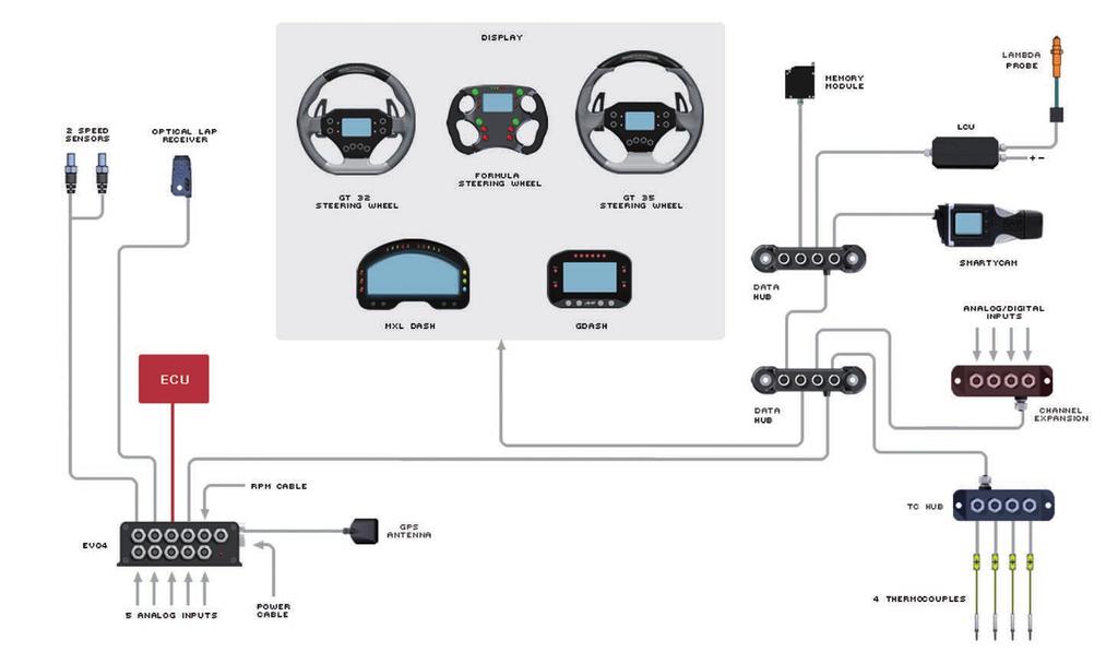
3 INTRODUCTION What is EVO4? EVO4 is a complete, compact and expandable data logger, suitable for installation on both car and motorcycle. What data reads? EVO4 acquires: 5 analog inputs, at a configurable frequency from 1 to 1000 Hz per channel. These signals can be: 0-5 Volt, mv, 0-50mV, thermocouples K. 2 digital inputs, suitable to receive signals from speed sensors. 1 RPM input, suitable to receive signals from low voltage of the coil or square wave 0-12 Volts. Data coming from internal triaxial accelerometer. Data from the internal GPS with external antenna. Data coming from the engine control unit (ECU). There are three hardware protocols available: CAN, RS232 and Linea K. Hundreds of ECU are fully supported. The lap time transmitted from the infrared receiver. The internal temperature of the system. What is the maximum frequency of acquisition possible? It is possible to acquire signals at a maximum total frequency of 5000 samples per second (i.e Hz). How much memory is available? EVO4 has 16 MB of non-volatile memory capable of recording more than 4 hours of data at a total frequency of 500 samples per second. To what purpose you can use the GPS? The integrated GPS is useful for different purposes. Lap time calculation: A large database of world tracks are avaliable. The coordinates of the finish line are available for meny world tracks. When turned on, EVO4 recognizes which track you are at and uses the coordinates to calculate the lap time with high precision. Measurement of the speed of the vehicle: In contrast to the measurement of the wheel speed, the speed measure based on GPS signals is not affected by the variation of the size of the wheel (due to the centrifugal force, the crushing and, in case of bikes, the inclination of the bke itself) and is thus more precise. Analysis of the trajectories: GPS receiver is an important tool to properly calculate the trajectory at every single lap and then to compare the different driving strategies. Which displays can be connected? EVO4 can be connected to the following dashes: GDash MXL Dash Formula Steering Wheel GT steering wheel 32/35 Which expansion modules are available? EVO4 can be connected to the following expansion modules (max.8) Channel Expansion: 4 additional analog channels 0-5 Volt. You can add up to 7 channel expansion. TCHub: 4 thermocouple channels. LCU-One Lambda Controller Memory Module: memory module with additional SD card. SmartyCam: the powerful camera with data overlay
4 INTRODUCTION EVO

5 CHAPTER 1 GETTING STARTED EVO4 Beacon Ecu - Can RS232 Exp. RPM K/L line USB GPS Output Speed 1-2 Power Connection 8-18 VDC GPS Antenna Analog Input Channel Status EVO


6 CHAPTER 1 GETTING STARTED EVO4 Kit includes EVO4 - GPS Antenna - RPM cable + K Line + Dig. out - Connection cable to ECU CAN/RS232 - USB cable for connection to PC - Software RaceStudio2 CD


7 CHAPTER 2 GENERAL INFORMATION Power. Power is provided by connecting the appropriate cable to the battery of your vehicle. It is not necessary to use special attention, because there is a stabilizer that regulates the internal power supply used by the system. So you can connect EVO4 without any problem to a NOT stabilized power source from 8 to 24 Volts. Even shutting down the system does not require special attention: when the power is turned off, a small battery in the system keeps the internal power supply on for a few seconds in order to properly close the internal data files. If your power is too spiky, an external power filter (code X60FLCEVO4), is available. Wiring diagram of external filter X60FLCEVO
.")

8 CHAPTER 2 GENERAL INFORMATION Data Recording. EVO4 is equipped with a 16 MB circular memory *, capable of recording 8 million samples. The test length that can be recorded depends on the sampling frequency (i.e. how many channels per second are recorded). For example, in case your acquisition has a global frequency of 500 Hz, which is fairly common, the system can record almost 4 hours of testing. If you require larger memory, the external Memory Module is available: it can manage a SD Card up to 16 Gygabyte SD and can provide virtually unlimited recording capability. * "Circular buffer" means that once it reaches saturation, the oldest data are overwritten by the most recent n The LED on the front shows: n 1 Hz blink : Stand-by status n Solid state : Data recording in progress n 3 Hz blink: system configuration problems n Flashing in alternating colors: firmware upgrade in progress Start/Stop Recording. EVO4 starts recording when one of the following situations persist for more than three seconds: n RPMs over 500 rpm threshold n Speed over 10 km / h Thanks to a pre-buffers, EVO4 records also the three seconds before the engine starts. Data Download. After activating the Aim software Race Studio2, the data are transmitted to the PC using the USB cable supplied with the product. If you have recorded the test on the Memory Module, you can directly insert the SD card into your PC. At the end of the data download, you can delete the data in EVO4 or leave them in memory, to eventually download them to another PC. Status LED 14 15


9 CHAPTER 3 LINKS, SENSORS AND CONFIGURATIONS Links, Sensors and Configurations. You will see this screenshot: Here are the different EVO4 connection possibilities: n To ECU n To RPM signal n To speed signal n To analog inputs n To expansions n To the optical lap time receiver When connecting EVO4 to a sensor, to ECU, or to an expansion module, you must also configure it in order to make EVO4 record the proper data. In particular, per every channel you have to define: n The connected sensor n The frequency acquisition of the sensor n The unit of measure Please use Aim software RaceStudio2 for system configuration. RaceStudio2 Configuration. In this chapter it is explained how to configure EVO4 with RaceStudio2 software. Connect EVO4 to your PC and run RaceStudio2. -> Select the button "Device Configuration" -> Select EVO4. 1 Press the New button and fill in the required fields. You must now define the parameters of the system. Each point will be explained in more depth in the dedicated chapter


10 CHAPTER 3 LINKS, SENSORS AND CONFIGURATIONS System Configuration. In the following RaceStudio2 page you can set: n How RPMs are acquired: from ECU data stream or reading a digital signal. n The maximum rpm value. n The division factor of the engine revolutions, ie the constant for which to divide the digital pulses number in order to obtain the correct value. n How to get the gear number: by calculation, potentiometer or ECU. n To use GPS in order to get lap time n To select a speed signal as Reference Speed. n How to manage digital output. Channels Configuration. In the following RaceStudio2 page you can define: n Which channels are enabled. n The type of sensor connected. n The sampling frequency. n The unit of measure


11 CHAPTER 4 ECU CONNECTIONS ECU Connections. EVO4 can acquire data from all the ECU published on the list on our website: This list includes about 500 different protocols and is constantly being updated, since all the ECUs are often improved and new models appear. When possible, we have explain how to configure your ECU to ensure compatibility between the data flow transmitted and what the protocol is designed to manage. From the hardware point of view, EVO4 is compatible with all currently available connections: CAN, RS232 or line K. If you need a CAN or RS232 connection, you must connect the cable to the connector labeled "ECU"; if you have to use the OBDII K Line, please use the connector labeled "rpm / K". n 2. Please read the documentation about your ECU in and identify the name of the proper software driver. n 3. Configure EVO4 setting that software driver in RaceStudio2. (1) n 4. Select the channels to be recorded. n 5. Send the configuration to EVO4. (2) The steps to manage the data coming from the ECU are: n 1. Determine which hardware connection is available for your ECU. If your ECU transmits the data to CAN or RS232, you need to connect the cable (Shown below left) to the connector labeled ECU. If it is equipped with a K line, you must use the cable (shown below right) and connect to the connector labeled "rpm / K". 1 2 Please refer to drawings listed in the appendix for further information regarding these cables
 n From the low voltage (from 150 to 400 V) of the coil.")
12 CHAPTER 5 THE RPM CHANNEL The RPM Channel. EVO4 can get the RPM signal in many different ways: n From ECU n Through a square wave signal (8 to 50 V) n From the low voltage (from 150 to 400 V) of the coil. n From the spark plug by converting the inductive RPM signal read from the spark plug into a square wave signal. In this case you must use an optional RPM adapter Code X10ADRPM000. The connection cable is in the kit and its code is You will find the technical drawing in the Appendix. The following image shows an example of wiring for the ignition system. The output cable, labeled gray tach, which can be acquired directly from EVO4 through the 5-50 volts. input, is shown here: n How to read RPM from ECU To get RPM from the ECU, connect EVO4, configure it as shown in the previous paragraph and enable RPM acquisition from ECU. In this case, RPM is of course just one of the many data flowing from your ECU to EVO4. n Acquiring the RPM via a 5-50 V square wave signal or coil ( V) In case your engine is not managed by any ECU, EVO4 can read the signal from the low voltage of the coil (whose peak can be from 150 to 400 V) or from a possible square wave (the peak can be from 5 at 50V.) The connector labeled "rpm / K", reported in Figure 13, receives the signals: n Low coil voltage V on Pin 1 n 4-50 V square wave on pin
13 CHAPTER 5 THE RPM CHANNEL If an output is not available from the ignition system, the system has to be connected to the low voltage of the coil. The coil from which to get the signal, is schematically shown in the image below. n Point 1 Is the low voltage input of the coil. n Point 2 Is connected to the spark plug. n Point 3 Is connected to the positive pole of the battery (+12 V). Shows an example of connection between coil and spark plug. The voltage at the points indicated by the numbers 1, 2 and 3 is shown


14 CHAPTER 5 THE RPM CHANNEL In order to properly configure EVO4 using the control panel you must: n Ensure AIM sensor is selected. n Define "max RPM." n Select the possible multiplication factor (RPM factor). Its value is typically 1 for two-stroke engines and four-stroke multi-cylinder, and 2 for single-cylinder four-stroke engines. n When the RPM signal is noisy Sometimes the signal from a low voltage point 0-50 V of the coil is particularly noisy and EVO4 does not read RPM properly, as in the examples: Dirty signal from the ECU Dirty signal from the coil Filtered wave signal In such cases, the filter shown in Fig.17 (Code X05ADRPMM30) can be useful. The input of the filter must be connected to the signal RPM, and the output to the input square wave EVO4 for 5-50 V (pin 3 of connector rpm / K)


15 CHAPTER 6 THE SPEED CHANNEL The Speed Channel. EVO4 can receive the speed signal from three different sources: n The ECU n The Built - in GPS receiver n The two digital channels It is possible that EVO4 receive and store different values of speed at the same time: the more powerful ECUs transmit up to four wheel speed values; considering speed values that come from GPS and from the two digital channels, there may be 7 different speed values. *Note that even if EVO4 can read and record up to seven values of speed, only ONE of these is used for some special functions, such as: n Gear calculation n Distance measurement n Data visualization in analysis software This speed is called Reference Speed and is defined in the software RaceStudio2. n Speed read from ECU If your ECU sends the value of speed in its data stream, it is possible to read, record and show that information. Simply enable the channel in RaceStudio2 and set define this speed as "Reference Speed." n Speed read from GPS receiver The GPS receiver integrated in EVO4 is configured in order to obtain the best performance in terms of reactivity and accuracy. We know that GPS signals are extremely weak, only 20 watts, and are transmitted from satellites at km away. Data accuracy can therefore sometimes be not as good as we would like. However, we can say that it is generally more than satisfactory and that GPS speed is very often better than wheel speed. ECU - CAN - RS232 GPS Output Speed 1-2 GPS Antenna


16 CHAPTER 6 THE SPEED CHANNEL n Speed read from the wheel EVO4 has two wheel speed inputs, in the same "speed" connector: n For configuring wheel speed parameters. Enter the Program Configuration panel and after enabling the channel desired speed (speed 1, speed 2 or both), set the wheel circumference and the number of pulses per revolution: The digital sensor X05SNBS00 detects the presence of a metallic tooth placed at a distance between 0.5 and 2 mm. 1 2 If you wish to acquire two speed inputs, you must use the cable code:

17 CHAPTER 7 ANALOG INPUTS Analog Inputs. EVO4 has five 12 bits analog inputs, recorded up to 1000 times per second each. You can connect 0-5 Volt signals, ratiometric potentiometers, pressure sensors, thermo-resistances and K-type thermocouples. Please, follow the steps: 1 Connect the sensor to the desired input 2 Enable the channel in the Channels table 3 Select the proper sensor type; sensors of many different types are properly handled, such a: Temperature sensors, Pressure Sensors, Potentiometers, Generic Sensors. 4 Set the sampling frequency 5 Set the unit of measure. n Temperature sensors K thermocouples Thermo-PT100 resistors Temperature sensors VDO n Pressure Sensors VDO C VDO C VDO C MSI 0-2 bar MSI 0-5 bar MSI 0-10 bar MSI psi n Potentiometers Distance Zero-based Zero Central n Generic Sensors 0-50 mv V 32 33


18 CHAPTER 7 ANALOG INPUTS A triaxial accelerometer is to be properly configured. When selected, the following screen appears: After having transmitted the configuration to EVO4, you must calibrate the sensor by pressing the button Transmit. 1 The calibration is used to define the range of some sensors such as potentiometers and accelerometers. 2 On this screen you can define the direction of installation EVO4. Simply select the image consistent with your installation. The three signals from the accelerometer are automatically related to the proper directions
 n Speed n Longitudinal acceleration n Latitudinal acceleration")

19 CHAPTER 8 GPS GPS. The integrated GPS in EVO4 provides the following information, updated ten times per second: n Position (latitude, longitude, altitude) n Speed n Longitudinal acceleration n Latitudinal acceleration n How to configure In order to use GPS data to compute lap times and split times, you have to: n Properly configure EVO4. n Transmit EVO4 the coordinates of the finish line and split lines. In the case EVO4 knows the finish line of the track and split coordinates, it can also calculate: n Lap times n Split times n Test length To transmit track information to EVO4, use GPSManager software, as explained in the dedicated chapter. To configure EVO4, access the Setup Menu and set GPS Lap Timer.(1) You can set Finish and Split line coordinates in two different ways: n Use the software GPS Manager to transmit information relating to the tracks where you are going to drive. EVO4 will automatically recognize the track and will use the proper coordinates. n Set the finish line coordinate directly on the track. This can be done only if EVO4 is connected to a dash

20 CHAPTER 8 GPS MANAGER SOFTWARE GPS Manager Software By GPS Manager you can update, modify, transmit and receive to and from EVO4 the coordinates of finish line and split points of all the tracks where you are going to run. 8 When opening the software, if there is no system connected to your PC via USB cable, you will see the screen shown. As you can see, the screen is divided into two parts. On the left you see the track list, split in dependance of the countries of origin. If available, you will see the track layout and the type of vehicle that usually race on the track: car, motorcycle or kart. 7 On the right side of the screen, you will find a big picture of the track Track management command Selection window for dynamic filters Track type: car, bike, karts Track data manager Track shape, with starting line and split points position Small track shape Track selection Open/Close Country track data
 that is to say, are recorded and used every time you use GPSManager, or dynamic, (2) that are not saved when quitting the program. 2 n Static Filters.")
 merging different characteristics.")
21 CHAPTER 8 GPS MANAGER SOFTWARE Filters in track data base management. In order to only see tracks you need, you can filter the list of tracks in different ways. The filters can be static, (1) that is to say, are recorded and used every time you use GPSManager, or dynamic, (2) that are not saved when quitting the program. 2 n Static Filters. A static filter is activated by the button below. The window shown will appear. n Dynamic Filters. The Dynamic filters are activated in the box at the top left of the screen: The dynamic filters allow you to further filter the tracks (in fact the car) merging different characteristics. 1 For example, writing "Spain closed," you will see only closed circuits for cars in Spain. It will allow you to select nations, the type of vehicle and type of circuit. The lists show only countries, vehicles and types of circuit present at least once in the database. For example, if you have not used any track in Germany, this country will not appear in the list. By default all countries, types of vehicle and tracks are abilited. If you are interested in only the car tracks, for example, you must disable karts and motorcycles
 Enter the name of the track.")


22 CHAPTER 8 GPS MANAGER SOFTWARE How to add a new track to the PC database. To add a new track 1) Press the button New 1 You can now select the file.gpk, containing the coordinates of all the points of your test. 2) Enter the name of the track. 3) Enter the required information: Country, Type of circuit (Closed, Oval or Open) (asphalt, dirt, ice, water). Finally, using the icon buttons, set the type of vehicle that usually run on the circuit: Cars, Motorcycles or Karts. If you have already run a test on the track and have downloaded data, you can associate the shape of the track, pressing the Load Track button. 2 3 The shape of the track appears, splitted in different laps of the test. It is possible to scroll through the different laps, to zoom, to rotate the drawing. After having selected the desired lap, push OK for saving the image of that lap. That image will be used as a reference shape for the future. Finish line coordinates are read from the.gpk file but can be modified as desired in one of the following ways: Define the coordinate by hand (1) Position the cursor on the desider point of the track and click the pushbutton Cursor Pos (2) In case of a Point to Point track, it is obviously useful to define the coordinates of the starting and finish line. Push OK for saving the configuration


23 CHAPTER 8 GPS MANAGER SOFTWARE How to modify track data in the PC database. How to read, write and delete tracks information in EVO4. Click the icon. The window containing the data of the track you can edit at will. Connect your system to your PC using the USB cable. The GPS Manager screen will display two lists: on the left, the tracks in your PC and on the right, the tracks in EVO4. EVO4 manages only the name of the tracks and coordinates of the finish and split points, but not their country or the shape


24 CHAPTER 8 GPS MANAGER SOFTWARE n To transmit track information to EVO4 Select tracks to be submitted by clicking on the square check, or double-click on the name of the track. n To receive track information from EVO4 Select tracks to be submitted by clicking on the square check, or double-click on the name of the track n To erase a track s information from EVO4. Select the track to be erased in the right panel and press "Delete Sel". n To modify track s information in EVO4 You can only change a track name in the EVO4 track list. To do this, double click on it. A window will appear containing the name ready for editing. 1 2 n Drag in the right panel or press the button. n The tracks information are updated in EVO4 panel. n Drag in the left panel or press the button. n Tracks information are updated in the PC list


25 CHAPTER 9 DATA SHEET Pinout EVO4. USB Cable for EVO
26 CHAPTER 9 DATA SHEET RPM, Gear flash and K Line cable for EVO4. EVO4 CAN and serial ECU connection cable
27 CHAPTER 9 DATA SHEET EVO4 K and L line cable with OBDII connection. EVO4 CAN cable with OBDII connection
 n CAN protocol for external expansion modules n ECU Interface n 5 KHz total sampling frequency n USB cable for data download n Memory: 16 Mb n External power: 9-15 V n Power")
28 CHAPTER 9 DATA SHEET EVO4 n 5 fully configurable analog channels n 2 speed channels n 1 digital RPM channel n 1 tri-axial internal accelerometer n Integrated GPS module n Laptime (magnetic/optical lap and GPS lap) n CAN protocol for external expansion modules n ECU Interface n 5 KHz total sampling frequency n USB cable for data download n Memory: 16 Mb n External power: 9-15 V n Power consumption: ma at 12V n Dimensions: 123 x 30 x 42,5 mm n Weight: 260g n Waterproof IP67 Our web site aim-sportline.com is constantly updated. We try to share with you our experiences about our products and how to use them in the tracks all over the world. Please, constantly check it and download the last versions of the firmware of your products
CONSTRUCTIVE DOCUMENTATION 09/06/2003 WIRING. Dash ST1. Logger s pinout. How to power the gauge
 AIM DashST1 CONSTRUCTIVE DOCUMENTATION 09/06/2003 WIRING Notes: general-purpose wiring for Dash ST1. Version 1.01 Dash ST1 167 [6.57] GEAR 87 [3.43] 27 [1.06] x1000 rpm mod.416tg Dimensions in millimetres
SSI-4 PLUS User Manual
 SSI-4 PLUS User Manual 1 SSI-4 PLUS... 2 1.1 Getting to Know the SSI-4 PLUS... 2 1.2 Channel Functions... 3 2 Wiring and Setup... 3 2.1 Powering the SSI-4 PLUS... 3 2.2 5V for External Sensors... 4 2.3
Mini-Expansion Unit (MEU) User Guide V1.2
 User Guide V1.2") Mini-Expansion Unit (MEU) User Guide V1.2 Disclaimer Although every care is taken with the design of this product, JT Innovations Ltd. can in no way be held responsible for any consequential damage resulting
Mini-Expansion Unit (MEU) User Guide V1.2 Disclaimer Although every care is taken with the design of this product, JT Innovations Ltd. can in no way be held responsible for any consequential damage resulting
0Introduction. TECHNICAL DOCUMENTATION 20/02/2009 PRESSURE Brake pressure PSI
 TECHNICAL DOCUMENTATION 20/02/2009 PRESSURE Brake pressure Notes: technical documentation, dimensions and pinout of brake pressure sensors sensors 0-2000 PSI Release 1.01 0-2000 PSI 0Introduction 0-2000
MoTec ECU MoTec Dash User manual for connection with ECU Bridge and SmartyCam
 MoTec ECU MoTec Dash User manual for connection with ECU Bridge and SmartyCam Foreword This tutorial helps you connecting ECU Bridge and SmartyCam to MoTec Dash using the CAN Bus. Supported MoTec Dashes
QUICK START GUIDE. AStrO. Ver Toll Free : 1 (877) Visit :
 Visit :") QUICK START GUIDE AStrO Ver.10.309 Toll Free : 1 (877) 462-7296 Visit : 1 Thank you for purchasing the latest in data acquisition technology, the AStrO. We hope that it surpasses your expectations. This
QUICK START GUIDE AStrO Ver.10.309 Toll Free : 1 (877) 462-7296 Visit : 1 Thank you for purchasing the latest in data acquisition technology, the AStrO. We hope that it surpasses your expectations. This
GPS-G5 User s Manual
 GPS-G5 User s Manual Contents Using the GPS... 1 Description...1 Electrical Connections...2 Mounting...3 GPS Configuration...3 GPS Operation...3 Logging Device Configuration...4 Data Analysis...5 Specifications...
Portable Multi-Channel Recorder Model DAS240-BAT
 Data Sheet Portable Multi-Channel Recorder The DAS240-BAT measures parameters commonly found in process applications including voltage, temperature, current, resistance, frequency and pulse. It includes
Quick start / system check to ensure the DL1CLUBGTCUP is operating correctly
 Data Logger Quick start / system check to ensure the DL1CLUBGTCUP is operating correctly This test MUST be performed with the supplied SD-card inserted, power ON and in open air conditions (outside and
KMT - Kraus Messtechnik GmbH
 KMT - Kraus Messtechnik GmbH Gewerbering 9, D-83624 Otterfing, Germany, 08024-48737, Fax. 08024-5532 Home Page http://www.kmt-telemetry.com, Email: info@kmt-telemetry.com User Manual CTP8-Rotate 8 (4)
DragonLink Advanced Transmitter
 DragonLink Advanced Transmitter A quick introduction - to a new a world of possibilities October 29, 2015 Written by Dennis Frie Contents 1 Disclaimer and notes for early release 3 2 Introduction 4 3 The
Nikon D7100 Camera Kit. -Checklist and Operations Manual-
 Airborne Digital Reconnaissance System (ADRS) Nikon D7100 Camera Kit -Checklist and Operations Manual- V4.2 October 21, 2014 National Headquarters, Civil Air Patrol 2 1.0 Equipment Pre-Mission Check 1.1
----STAR S86 GPS Receiver. User Guide. SOUTH CO., Ltd.
 ----STAR S86 GPS Receiver User Guide SOUTH CO., Ltd. www.southsurveying.com Sales@SOUTHsurveying.com 2 CONTENTS Chapter 1 Introduction... 1 STAR S86 GPS - System Summary... 1 Technical Specification...
BR2 Lap Beacon Manual
 MoTeC BR2 Lap Beacon Manual Contents Introduction... 1 Overview... 3 Operation...3 Orientation...5 Range...5 Alignment...5 Verifying Operation...6 Split Beacon Use...6 Configuration - Quick Start... 7
INSTRUCTION MANUAL Version 1.0
 INSTRUCTION MANUAL Version 1.0 Camera Geotagger For Nikon or Canon GPS plus Beidou Barometric altimeter Position Tracing Logger Shutter Release Remoter LCD display Bluetooth technology GPS Contents Introduction
Vehicle Data Display and Logger Installation and Operation Manual Rev Focus Applied Technologies
 Vehicle Data Display and Logger Installation and Operation Manual Rev 1. 1-215 Focus Applied Technologies INTRODUCTION This Vehicle Data Display and Logger is designed as a robust display and logger for
maxon document number:
 maxon document number: 791272-04 1 Table of contents... 2 2 Table of figures... 3 3 Introduction... 4 4 How to use this guide... 4 5 Safety Instructions... 5 6 Performance Data... 6 6.1 Motor data... 6
Frequency selective monitoring and logging of environmental electromagnetic fields
 FREQUENCY SELECTIVE EMF AREA MONITOR AMS-8060 Frequency selective monitoring and logging of environmental electromagnetic fields Up to 20 fully programmable frequency bands Real built-in spectrum analyser
A Super trainer with advanced hardware and software features only found in very expensive equipment.
 PLC Trainer PTS T100 LAB EXPERIMENTS A Super trainer with advanced hardware and software features only found in very expensive equipment. You won t find any similar equipment among our competitors at such
BandMaster V Manual. Installation
 BandMaster V Manual Installation Installing and configuring the BM-5 BandMaster V is a simple process. All the configuration process is done from the front panel. Installation and configuration steps are
SAE Formula Car Data Acquisition & Display System. Joseph Groe, Michelle Ohlson, & Miles Homler Advisor: Professor Gutschlag
 SAE Formula Car Data Acquisition & Display System Joseph Groe, Michelle Ohlson, & Miles Homler Advisor: Professor Gutschlag Agenda Problem Background Problem Statement System Diagram Project Functional
6 Repton Close Basildon Essex SS13 1LE United Kingdom +44 (0)
") 6 Repton Close Basildon Essex SS13 1LE United Kingdom +44 (0) 1268 904124 info@liferacing.com www.liferacing.com The F88GDi4 ECU sets the benchmark for integrated direct injection engine management. Based
6 Repton Close Basildon Essex SS13 1LE United Kingdom +44 (0) 1268 904124 info@liferacing.com www.liferacing.com The F88GDi4 ECU sets the benchmark for integrated direct injection engine management. Based
Jaguar Motor Controller (Stellaris Brushed DC Motor Control Module with CAN)
") Jaguar Motor Controller (Stellaris Brushed DC Motor Control Module with CAN) 217-3367 Ordering Information Product Number Description 217-3367 Stellaris Brushed DC Motor Control Module with CAN (217-3367)
Jaguar Motor Controller (Stellaris Brushed DC Motor Control Module with CAN) 217-3367 Ordering Information Product Number Description 217-3367 Stellaris Brushed DC Motor Control Module with CAN (217-3367)
Uni-Mux XQL Multi-Channel Data Acquisition Module
 Uni-Mux XQL Multi-Channel Data Acquisition Module Uni-Mux XQL Multi-Channel Data Acquisition Module * 8 channel differential inputs. * 16 channel single ended inputs. * User programmable via P.C. software.
AiM Infotech. MoTec M4 and M48 ECUs. Release 1.02
 AiM Infotech MoTec M4 and M48 ECUs Release 1.02 This tutorial explains how to connect MoTec ECUs to AiM devices. 1 Supported models MoTec supported models are: M4 M48 2 Software check (M48 only) and configuration
KMT - Kraus Messtechnik GmbH
 KMT - Kraus Messtechnik GmbH Gewerbering 9, D-83624 Otterfing, Germany, 08024-48737, Fax. 08024-5532 Home Page http://www.kmt-telemetry.com, Email: info@kmt-telemetry.com CTP8-Rotate 8 (4) channel telemetry
DIS-5010A, DIA-512A. Data Acquisition System for Crash Test AUTOMOTIVE TEST EQUIPMENT
 , Data Acquisition System for Crash Test 5-40 On-vehicle Data Logger for Crash Test On-vehicle Airbag Timer for Crash Test On-vehicle Data Logger for Crash Test On-vehicle unit designed to acquire 32 channels
SPEEDBOX Technical Datasheet
 SPEEDBOX Technical Datasheet Race Technology Limited, 2008 Version 1.1 1. Introduction... 3 1.1. Product Overview... 3 1.2. Applications... 3 1.3. Standard Features... 3 2. Port / Connector details...
Table Of Contents Overview of the operating buttons... 4 The functions of the datalogger... 5 How to start logging from the default settings...
 Table Of Contents 1. Overview of the operating buttons... 4 2. The functions of the datalogger... 5 2.1 LOG... 5 2.2 METER... 5 2.3 REVIEW... 5 2.4 TIME / date... 5 2.5 START time / date... 5 2.6 INT log
GPS (GLOBAL POSITIONING SYSTEM)
") GPS (GLOBAL POSITIONING SYSTEM) What is GPS? GPS, standing for Global Positioning System, is becoming common nowadays. Following is a brief introduction. The American Defense Department developed GPS originally
GPS (GLOBAL POSITIONING SYSTEM) What is GPS? GPS, standing for Global Positioning System, is becoming common nowadays. Following is a brief introduction. The American Defense Department developed GPS originally
Correlation of Voltage and Temperature Measurement
 MEASURpoint Correlation of Voltage and Temperature Measurement Precision Measurement Instrument MEASURpoint is an ultra-accurate instrument for any combination of temperature and voltage to be measured
Studuino Icon Programming Environment Guide
 Studuino Icon Programming Environment Guide Ver 0.9.6 4/17/2014 This manual introduces the Studuino Software environment. As the Studuino programming environment develops, these instructions may be edited
RC Altimeter #2 BASIC Altitude data recording and monitoring system 3/8/2009 Page 2 of 11
 Introduction... 3 How it works... 3 Key features... 3 System requirements... 3 Hardware... 4 Specifications... 4 Using the RC Altimeter #2 BASIC module... 5 Powering the module... 5 Mounting the module...
EMS EM-Tech Race Dash Manual Version 3.1
 EMS EM-Tech Race Dash Manual Version 3.1 Thank you for purchasing an EMS Race Dash. EMS Computers Pty Ltd Unit 9 / 171 Power St Glendenning NSW 2761 Australia Ph: +612 9675 1414 Email: support@fuel-injection.com
OVEN INDUSTRIES, INC. Model 5C7-362
 OVEN INDUSTRIES, INC. OPERATING MANUAL Model 5C7-362 THERMOELECTRIC MODULE TEMPERATURE CONTROLLER TABLE OF CONTENTS Features... 1 Description... 2 Block Diagram... 3 RS232 Communications Connections...
Telemetrie-Messtechnik Schnorrenberg
 Telemetrie-Messtechnik Schnorrenberg CT16-Wheel User manual TMS Telemetrie-Messtechnik Schnorrenberg Dipl.-Ing. Werner Schnorrenberg Habichtweg 30, D-51429 Bergisch Gladbach, Tel: 02204-9815-52, Fax: 02204-9815-53,
AA-35 ZOOM. RigExpert. User s manual. Antenna and cable analyzer
 AA-35 ZOOM Antenna and cable analyzer RigExpert User s manual . Table of contents Introduction Operating the AA-35 ZOOM First time use Main menu Multifunctional keys Connecting to your antenna SWR chart
Telemetrie-Messtechnik Schnorrenberg
 Telemetrie-Messtechnik Schnorrenberg CTP8-Rotate 8 (4) channel telemetry for rotating applications like wheels or rotors, high signal bandwidth, 16bit, software programmable Inputs for STG, TH-K, ICP or
GPS Position Sensor PS-2175
 In s tr u c ti o n M a n u a l 012-09919A GPS Position Sensor PS-2175! Table of Contents Contents Introduction........................................................... 3 Theory of Operation....................................................
MT32 Telemetry. KMT - Kraus Messtechnik GmbH. Multi channel telemetry system for rotating application. Powering (rotor) by battery or inductive
 by battery or inductive") KMT - Kraus Messtechnik GmbH Gewerbering 9, D-83624 Otterfing, Germany, 08024-48737, Fax. 08024-5532 Home Page http://www.kmt-telemetry.com, Email: info@kmt-telemetry.com MT32 Telemetry Multi channel telemetry
KMT - Kraus Messtechnik GmbH Gewerbering 9, D-83624 Otterfing, Germany, 08024-48737, Fax. 08024-5532 Home Page http://www.kmt-telemetry.com, Email: info@kmt-telemetry.com MT32 Telemetry Multi channel telemetry
Powerful RISC CPU for advanced strategy execution Custom synchronous FPGA processor for engine position tracking up to 25,000 rpm
 F90F ECU The F90F ECU caters for advanced and challenging applications. The twin processor unit uses a high speed RISC processor for code execution and an additional large FPGA for high speed engine position
Brushed DC Motor Control. Module with CAN (MDL-BDC24)
") Stellaris Brushed DC Motor Control Module with CAN (MDL-BDC24) Ordering Information Product No. MDL-BDC24 RDK-BDC24 Description Stellaris Brushed DC Motor Control Module with CAN (MDL-BDC24) for Single-Unit
Stellaris Brushed DC Motor Control Module with CAN (MDL-BDC24) Ordering Information Product No. MDL-BDC24 RDK-BDC24 Description Stellaris Brushed DC Motor Control Module with CAN (MDL-BDC24) for Single-Unit
( F L O W I Z F A M I L Y )
") THE MOST ACCURATE BATTERY POWERED SYSTEM ( F L O W I Z F A M I L Y ) E l e c t r o m a g n e t i c c o n v e r t e r p o w e r e d b y b a t t e r i e s, s o l a r p a n e l o r D C p o w e r w i t h 4
THE MOST ACCURATE BATTERY POWERED SYSTEM ( F L O W I Z F A M I L Y ) E l e c t r o m a g n e t i c c o n v e r t e r p o w e r e d b y b a t t e r i e s, s o l a r p a n e l o r D C p o w e r w i t h 4
Opera Duo. Opera Duo. GeoRadar Division. a first class underground survey
 a first class underground survey Opera Duo Competitive advantages Designed around you A large, comfortable handle to make pushing an pulling easier, large wheels for better control and a balanced weight
MTY (81)
") This manual describes the option "d" of the SMT-BD1 amplifier: Master/slave electronic gearing. The general information about the digital amplifier commissioning are described in the standard SMT-BD1 manual.
This manual describes the option "d" of the SMT-BD1 amplifier: Master/slave electronic gearing. The general information about the digital amplifier commissioning are described in the standard SMT-BD1 manual.
CTP16-Rotate. KMT - Kraus Messtechnik GmbH
 KMT - Kraus Messtechnik GmbH Gewerbering 9, D-83624 Otterfing, Germany, 08024-48737, Fax. 08024-5532 Home Page http://www.kmt-telemetry.com, Email: info@kmt-telemetry.com CTP16-Rotate 16 channel telemetry
MINIMUM SYSTEM REQUIREMENTS
 Quick Start Guide Copyright 2000-2012 Frontline Test Equipment, Inc. All rights reserved. You may not reproduce, transmit, or store on magnetic media any part of this publication in any way without prior
Nebraska 4-H Robotics and GPS/GIS and SPIRIT Robotics Projects
 Name: Club or School: Robots Knowledge Survey (Pre) Multiple Choice: For each of the following questions, circle the letter of the answer that best answers the question. 1. A robot must be in order to
AIMS Radar Specifications
 Transmitted Frequency: Peak Radiated Power: Average Power: Antenna Beamwidth: 9.23 GHz 1 Watt (Optional 2 to 80 Watts) 6.25 microwatts up to 0.4 watts; < 1 milliwatt for most applications Fast-Scan (rotating):
Operation. Displayed channel. Measuring range. Status indication/ remote control Key lock Measuring mode/ time constant. Scale.
 Electronics & Software Type 5080A... Multichannel Laboratory This universal laboratory charge amplifier can be used for force and torque measurements with piezoelectric dynamometers or force plates. Piezoelectric
TOSHIBA MACHINE CO., LTD.
 User s Manual Product SHAN5 Version 1.12 (V Series Servo Amplifier PC Tool) Model SFV02 July2005 TOSHIBA MACHINE CO., LTD. Introduction This document describes the operation and installation methods of
GPT ENGINEERING VIA CADORE SEREGNO (MONZA/BRIANZA) ITALY
 ITALY") D GPS GPT ENGINEERING VIA CADORE 19 20038 SEREGNO (MONZA/BRIANZA) ITALY PHONES: +390362231023 / +390362220060 FAX: +390362239002 tech@gpt.it - www.gpt.it skype: gptengineering D-GPS Introduction The lap
D GPS GPT ENGINEERING VIA CADORE 19 20038 SEREGNO (MONZA/BRIANZA) ITALY PHONES: +390362231023 / +390362220060 FAX: +390362239002 tech@gpt.it - www.gpt.it skype: gptengineering D-GPS Introduction The lap
Powerful RISC CPU for advanced strategy execution Custom synchronous FPGA processor for engine position tracking up to 25,000 rpm
 F90A ECU The F90A ECU caters for advanced and challenging applications. The twin processor unit uses a high speed RISC processor for code execution and an additional large FPGA for high speed engine position
Hi-Inc ULP ( Ultra-Low-Power) Wifi Inclinometer with built-in datalogger
 Wifi Inclinometer with built-in datalogger") Hi-Inc ULP ( Ultra-Low-Power) Wifi Inclinometer with built-in datalogger www.beanair.com Product Video VIDE O 220g OVERVIEW ULP (Ultra Low Power) Wifi technology Embedded data logger: up to 5 million data
Hi-Inc ULP ( Ultra-Low-Power) Wifi Inclinometer with built-in datalogger www.beanair.com Product Video VIDE O 220g OVERVIEW ULP (Ultra Low Power) Wifi technology Embedded data logger: up to 5 million data
AX-3DS. ULP (Ultra-Low-Power) Wifi accelerometer sensor dedicated to shock. detection with built-in data logger
 Wifi accelerometer sensor dedicated to shock. detection with built-in data logger") ULP (Ultra-Low-Power) Wifi accelerometer sensor dedicated to shock detection with built-in data logger www.beanair.com Product Video VIDE O 220g OVERVIEW ULP (Ultra Low Power) Wifi technology Rugged aluminum
ULP (Ultra-Low-Power) Wifi accelerometer sensor dedicated to shock detection with built-in data logger www.beanair.com Product Video VIDE O 220g OVERVIEW ULP (Ultra Low Power) Wifi technology Rugged aluminum
Medidores de vibración salida RS232 Datalogger VT-8204 LUTRON manual ingles
 English usermanual VT-8204 Vibration Tachometer Your purchase of this VIBRATION TACHOMETER marks a step forward for you into the field of precision measurement. Although this VIBRATION TACHOMETER is a
LC-10 Chipless TagReader v 2.0 August 2006
 LC-10 Chipless TagReader v 2.0 August 2006 The LC-10 is a portable instrument that connects to the USB port of any computer. The LC-10 operates in the frequency range of 1-50 MHz, and is designed to detect
LinkAlign-60RPT Set-up and Operation Manual
 LinkAlign-60RPT Set-up and Operation Manual LinkAlign Setup and Operation Proprietary, Nextmove Technologies Page 1 LinkAlign Setup and Operation Proprietary, Nextmove Technologies Page 2 Description of
Using Motec Hundred Series ECU s with AEM CD-7 Displays. M400, M600, M800, M880 Transmitting Data Set #1
 Revision Date Initial Release Feb 10, 2017 Using Motec Hundred Series ECU s with AEM CD-7 Displays Supported Motec Hardware M400, M600, M800, M880 Transmitting Data Set #1 M84, M400, M600, M800, M880 Transmitting
Featherweight GPS Tracker User s Manual June 16, 2017
 Featherweight GPS Tracker User s Manual June 16, 2017 Hardware Configuration and Installation The dimensions for the board are provided below, in inches. Note that with the antenna installed, the total
Contents. Chapter 1 Brief Introduction of K9 series Chapter 2 K9 series mainframe The appearance of mainframe Interface...
 Contents Chapter 1 Brief Introduction of K9 series... 1 Chapter 2 K9 series mainframe... 2 2.1 The appearance of mainframe... 2 2.2 Interface... 2 2.3 The installation of battery... 3 2.4 Guiding light
MIDLAND PROGRAMING G14
 MIDLAND PROGRAMING G14 1. PROGRAMMING CAPABILITY Welcome to the MIDLAND Programming software! It s a programming software specifically designed for G14 and must be used in conjunction with the dedicated
SETTOPSURVEY, S.L. Bofarull 14, Barcelona (Spain) Phone: (+34) Fax: (+34)
 Phone: (+34) Fax: (+34)") USER MANUAL v.5 Settop Repeater 2 Index SETTOP Repeater... 3 Control Software... 5 SETTINGS: Configuration... 7 RADIO... 8 INTERNET SETUP: Configuration of the internet protocols... 10 CELLULAR MODEM:
USER MANUAL v.5 Settop Repeater 2 Index SETTOP Repeater... 3 Control Software... 5 SETTINGS: Configuration... 7 RADIO... 8 INTERNET SETUP: Configuration of the internet protocols... 10 CELLULAR MODEM:
Introduction...1 Overview...2. Beacon Transmitter...7. Beacon Receiver Trouble Shooting...15
 MoTeC Lap Beacon Manual Contents Introduction...1 Overview...2 Operation...2 ID Number...3 Lap Beacon Use...4 Split Beacon Use...4 Verifying Operation...5 Beacon Transmitter...7 Position...7 Spacing between
Long Range Wireless OSD 5.8G FPV Transmitter
 Long Range Wireless OSD 5.8G FPV Transmitter Built-in 10 Axis AHRS + MAVLINK + 600mW Support all flight controller and GPS 1 / 14 User's Guide Catalogue Product Instruction 3 Features 3 Specifications.4
SC16A SERVO CONTROLLER
 SC16A SERVO CONTROLLER User s Manual V2.0 September 2008 Information contained in this publication regarding device applications and the like is intended through suggestion only and may be superseded by
Speed Sensor Range (VBSS05 VBSS100_V4G) Features
 Features") Based on a range of high accuracy GPS engines, VBOX Speed Sensors offer the ultimate non-contact measurement solution. With 5 Hz, 10 Hz, 20 Hz and 100 Hz GPS update rate options available, the speed sensor
Based on a range of high accuracy GPS engines, VBOX Speed Sensors offer the ultimate non-contact measurement solution. With 5 Hz, 10 Hz, 20 Hz and 100 Hz GPS update rate options available, the speed sensor
Attitude and Heading Reference Systems
 Attitude and Heading Reference Systems FY-AHRS-2000B Installation Instructions V1.0 Guilin FeiYu Electronic Technology Co., Ltd Addr: Rm. B305,Innovation Building, Information Industry Park,ChaoYang Road,Qi
User Manual CTP4/8/16
 KMT - Kraus Messtechnik GmbH Gewerbering 9, D-83624 Otterfing, Germany, 08024-48737, Fax. 08024-5532 Home Page http://www.kmt-telemetry.com, Email: info@kmt-telemetry.com User Manual CTP4/8/16 4/8/16-channel
Height Limited Switch
 Height Limited Switch Manual version: 1.0 Content Introduction...3 How it works...3 Key features...3 Hardware...4 Motor cut-off settings...4 Specification...4 Using the RC HLS #1 module...5 Powering the
KMT - Kraus Messtechnik GmbH
 KMT - Kraus Messtechnik GmbH Gewerbering 9, D-83624 Otterfing, Germany, 08024-48737, Fax. 08024-5532 Home Page: http://www.kmt-telemetry.com, Email: info@kmt-telemetry.com Operating instructions RPM8000-OBD2
Micro-Trak All-In-One APRS Transmitter
 Micro-Trak All-In-One APRS Transmitter Hardware version 1.1, Manual Version 1.1 The MT-AIO is a self-contained, water resistant APRS transmitter/gps receiver designed for portable use. The MT-AIO is computer
inphoto ID Canon camera control software Automatic ID photography User Guide
 inphoto ID Canon camera control software Automatic ID photography User Guide 2008 Akond company 197342, Russia, St.-Petersburg, Serdobolskaya, 65A Phone/fax: +7(812)600-6918 Cell: +7(921)757-8319 e-mail:
STEPPING MOTOR EMULATION
 OPERATING MANUAL SERIES SMTBD1 OPTIONAL FUNCTIONS (Version 2.0) European version 2.0 STEPPING MOTOR EMULATION OPTION C This manual describes the option "C" of the SMT-BD1 amplifier: Stepping motor emulation.
Electromagnetic Field Meter SMP2
 SMP2 USER S MANUAL V 2.01 Safety, Quality, Service +34 93 320 80 55 info@wavecontrol.com Congratulations for your acquisition of a Wavecontrol SMP2. This Manual provides you with instructions for using
NEULOG PHOTO GATE LOGGER SENSOR GUIDE
 NeuLog photo gate logger sensor NUL-209 The NeuLog photo gate sensor can be used for any science experiment which involves taking accurate velocity and/or acceleration measurements especially in the field
NEULOG PHOTO GATE LOGGER SENSOR GUIDE
 NeuLog photo gate logger sensor NUL-209 Part# NL-2090 The NeuLog photo gate sensor can be used for any science experiment which involves taking accurate velocity and/or acceleration measurements especially
LinkAlign-360FER Set-up and Operation Manual
 LinkAlign-360FER Set-up and Operation Manual Proprietary, Nextmove Technologies Page 1 Proprietary, Nextmove Technologies Page 2 Table of Contents General Notes:... 4 Description of items included with
SeaGauge. User s Manual. Chetco Digital Instruments
 SeaGauge User s Manual Chetco Digital Instruments Copyright 2005 Chetco Digital Instruments, Inc. All rights reserved. SeaGauge is a trademark of Chetco Digital Instruments, Inc. SeaSwitch is a trademark
inphoto ID Canon and Olympus camera control software Automatic ID photography User Guide
 inphoto ID Canon and Olympus camera control software Automatic ID photography User Guide 2006 Akond company 197342, Russia, St.-Petersburg, Serdobolskaya, 65a Phone/fax: +7(812)600-6918 Cell: +7(921)757-8319
Introduction to the Analog Discovery
 Introduction to the Analog Discovery The Analog Discovery from Digilent (http://store.digilentinc.com/all-products/scopes-instruments) is a versatile and powerful USB-connected instrument that lets you
BeeLine TX User s Guide V1.1c 4/25/2005
 BeeLine TX User s Guide V1.1c 4/25/2005 1 Important Battery Information The BeeLine Transmitter is designed to operate off of a single cell lithium polymer battery. Other battery sources may be used, but
USB Multifunction Arbitrary Waveform Generator AWG2300. User Guide
 USB Multifunction Arbitrary Waveform Generator AWG2300 User Guide Contents Safety information... 3 About this guide... 4 AWG2300 specifications... 5 Chapter 1. Product introduction 1 1. Package contents......
X3M. Multi-Axis Absolute MEMS Inclinometer Page 1 of 13. Description. Software. Mechanical Drawing. Features
 Page 1 of 13 Description The X3M is no longer available for purchase. The X3M is an absolute inclinometer utilizing MEMS (micro electro-mechanical systems) technology to sense tilt angles over a full 360
Series DL8 Process Data Logger
 Series DL8 Process Data Logger Bulletin E-90-DL8 Specifications - Installation and Operating Instructions Input Jack for Interface Cable Security Eyelet Magnetic Strip 2.95 [75] Temperature Sensor 0.656
Test Bench Timing V3.1
 Test Bench Timing V3.1 Purpose:...1 Suggested Test Procedure:...1 Pre Run Setup:...1 Input Control:...1 Left Panel:...1 Setup and Outputs:...1 Channel Parameters:...1 Sensor:...1 Digital Graph:...1 Signal
VOLTAGE. User Guide ACCESSORIES. External Sensor DT140. for MicroLog EC600 and EC V ±0.05V ±3% (before calibration)
") External Sensor VOLTAGE DT140 Range: Resolution: Accuracy: Input impedance: Calibration: OV protection: 0-10V ±0.05V ±3% (before calibration) 3MΩ 2 calibration points ±30V ACCESSORIES User Guide for MicroLog
External Sensor VOLTAGE DT140 Range: Resolution: Accuracy: Input impedance: Calibration: OV protection: 0-10V ±0.05V ±3% (before calibration) 3MΩ 2 calibration points ±30V ACCESSORIES User Guide for MicroLog
The universal Data Acquisition system
 The universal Data Acquisition system experience INSPIRES TRUST MOPS a very unique data acquisition system! While other data acquisition systems just grow older and become more and more unattractive, the
EDS-400A COMPACT RECORDER. New KYOWA ELECTRONIC INSTRUMENTS CO., LTD.
 KYOWA ELECTRONIC INSTRUMENTS CO., LTD. COMPACT RECORDER EDS-400A Compact Dynamic Strain Recorder Entering the scene in advanced measurement of strain, vibration, pressure, load, etc. New www.kyowa-ei.co.jp
BRB900 GPS Telemetry System August 2013 Version 0.06
 BRB900 GPS Telemetry System August 2013 Version 0.06 As of January 2013, a new model of the BRB900 has been introduced. The key differences are listed below. 1. U-blox GPS Chipset: The Trimble Lassen IQ
MASTER/SLAVE TENSION CONTROL
 OPERATING MANUAL SERIES SMTBD1 OPTIONAL FUNCTIONS (Version 2.0) European version 2.0 MASTER/SLAVE TENSION CONTROL OPTION E This manual describes the option "E" of the SMT-BD1 amplifier: Master / Slave
LENORD. +BAUER... automates motion. Magnetic absolute rotary encoder GEL 2037 with heavy duty flange or tooth wheel adapter
 Magnetic absolute rotary encoder GEL 2037 with heavy duty flange or tooth wheel adapter LENORD +BAUER... automates motion. Technical information Version 01.12 General Multiturn absolute rotary encoders
Nikon D7000 Camera Kit
 Nikon D7000 Camera Kit -Checklist and Operations Manual- July 31, 2013 SRQ Composite Squadron, FLWG, Civil Air Patrol Page 1 of 30 1.0 Equipment Pre-Mission Check 1.1 Open the camera case and verify the
Tarocco Closed Loop Motor Controller
 Contents Safety Information... 3 Overview... 4 Features... 4 SoC for Closed Loop Control... 4 Gate Driver... 5 MOSFETs in H Bridge Configuration... 5 Device Characteristics... 6 Installation... 7 Motor
FAST SAMPLING CONVERTER
 FAST SAMPLING CONVERTER ML4-F1 HIGH SAMPLING RATE CONVERTER (UP TO 400 SAMPLES/SECOND) Warranty conditions are available on this website: www.isomag.eu only in English version INDEX TECHNICAL DATA... 3
MT3500 Hand-Held Engine Analyzer Safety Operation Regulations
 MT3500 Hand-Held Engine Analyzer Safety Operation Regulations - 1 - Chapter One Introduction A. Notice of Usage: MT3500 Hand-Held Engine Analyzer must be operated by trained professionals, who must know
EULAMBIA ADVANCED TECHNOLOGIES LTD. User Manual EAT-EOM-CTL-2. Alexandros Fragkos
 EULAMBIA ADVANCED TECHNOLOGIES LTD User Manual Alexandros Fragkos (alexandros.fragkos@eulambia.com) 11/28/2016 28/11/2016 User Manual User Manual 28/11/2016 Electro-Optic Modulator Bias Control Unit v2.0
Pinout User Manual. Version 1.0(Draft) Zesty Systems Inc
 Zesty Systems Inc") Pinout User Manual Version 1.0(Draft) Zesty Systems Inc. 2016.7.27 Index What you need to use Pinout... 3 How to get connected to Pinout... 3 Introduction of Pinout... 4 Pinout hardware overview... 5 Camera
Pinout User Manual Version 1.0(Draft) Zesty Systems Inc. 2016.7.27 Index What you need to use Pinout... 3 How to get connected to Pinout... 3 Introduction of Pinout... 4 Pinout hardware overview... 5 Camera
Opera Duo. GeoRadar Division
 Utilities Detection and Mapping Opera Duo: real-time detection of pipes RIS MF Hi-Mod: Utilities mapping on all zones All rights reserved to IDS 2 Utilities Detection and Mapping Stream: massive arrays
SA-320 Installation Guide SA-320. Installation Guide. Date: Mar, 2011 Version: 2.5. All Rights Reserved
 SA-320 Installation Guide Date: Mar, 2011 Version: 2.5 All Rights Reserved Page 1 TABLE OF CONTENTS 1. Product Overview......3 1.1 Main Features...3 1.2 Applications.....3 1.3 Package Content.....3 2.