BRB900 GPS Telemetry System August 2013 Version 0.06
|
|
|
- Garry Robertson
- 5 years ago
- Views:
Transcription

1 BRB900 GPS Telemetry System August 2013 Version 0.06 As of January 2013, a new model of the BRB900 has been introduced. The key differences are listed below. 1. U-blox GPS Chipset: The Trimble Lassen IQ gps module has been replaced with a u-blox NEO-6. This new chipset offers higher sensitivity and quicker lock times. However, it lacks non-volatile memory to store configuration information so it must be configured at poweron. For this reason, the smart version is required. The basic version is no longer available. 2. Larger On-board memory: The on-board memory has been upgrade to 1 megabit. This is eight times larger than the original, and can store almost 2 ½ hours of data at a 1 Hz rate. 3. No G-switch: The G-switch that was previously used to detect launch has been eliminated. With the larger memory mentioned above, positions will be recorded for 2 ½ hours after the unit is powered on until the memory fills and recording stops. Or, if the wrap option is set, 2 ½ hours before the end is reached and recording starts again at the beginning. 4. No integrated rubber duck antenna: The option to mount an RP-SMA antenna directly to the transmitter board has been eliminated. This mounting option often resulted in broken transmitters due to the stress caused during launch, landing, or ejection events. The recommended antenna option is now a simple wire whip. A u-fl cable + RP-SMA antenna is also available. 5. Configuration Program: Because of the larger on-board memory, a new windows program is required. Until these changes get integrated into one program, please use the xb3.exe version instead of brb900.exe. 1. Overview: The BRB900 Telemetry System consists of a GPS receiver and RF transmitter paired with a matching RF receiver. The GPS transmitter is placed in the object to be tracked, and the receiver is located at the base station. The GPS onboard the transmitter computes the position of the object being tracked and transmits this information over the RF data link. The receiver decodes the data, which shows in real time, the precise location of the object being tracked.
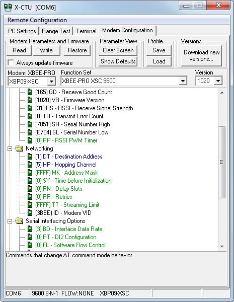
2 2. Quick Start Guide: All BRB900 transmitters and receivers arrive preconfigured and ready to run OUT OF THE BOX, no additional configuration necessary. Simply apply power to the transmitter and make sure the GPS module has a clear view of the sky (initial lock times may take as long as 15 minutes). Turn on the LCD receiver (push the switch UP turn it on) or plug the USB only receiver into your PC to start receiving packets. For the USB receiver without the LCD, you will also have to run some terminal emulation (e.g. Hyperterm or TeraTerm) program to view the GPS data stream. Baud rate should be set to N Configuration: Each transmitter and receiver are paired by programming a common transmit ID into the transmitter and receiver. Receivers can only receive data packets from transmitters with the same transmit ID, other transmitters will be ignored. It is possible to have multiple transmitters with the same transmit ID. They can be distinguished from each other by the uniq serial number that is embedded in the transmit packet. 4. BRB 900 Transmitter The transmitter consists of a GPS receiver, 900 MHz spread spectrum transmitter, and battery regulator circuitry. Power is supplied by connecting J2 to J3. The LED will flash rapidly for several seconds and stop until GPS lock is obtained. Then it will blink at 1 Hz when lock is obtained. The LED will blink when GPS lock is obtained. To use the software to configure the transmitters, follow this steps: a) Plug in the USB interface to the PC b) Start the software and select the proper com-port c) Apply power to the device. Note that the LED will beging to flash rapidy d) Connect the 5-pin headers together. e) WHILE THE LED IS STILL RAPIDLY FLASHING, click on read 5. BRB900 Receiver The base level receiver consists of a 900 MHz spread spectrum radio module with a USB interface that appears as a virtual serial port. Power is provided via the USB interface, and data is transmitted at 9600 baud, 8 data bits, No parity 1 stop bit ( N-1). The RF transmitter may be configured using the X-CTU programming software over the USB link. The LCD version of the transmitter adds a microcontroller and LCD display. The LCD display is battery powered, and can be charged over the USB port. The RF transmitter is configured using the X-CTU programming software over the USB link. The LCD receiver can be configured to decode two data packet types sent from the transmitter, $GPGGA and $BRBTX. Switching between the modes is accomplished by turning the power on while the configuration button is pressed. The receive mode will be stored in non-volatile memory. It is NOT possible to upgrade from the base level to the enhanced version of the BRB900 Receiver. 6. Transmit Modes There are two transmit modes:

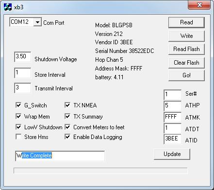
3 $BRBTX Summary: $BRBTX sentence is sent over the RF link at a user defined rate. This mode results in the lowest power consumption and minimal use of the RF bandwidth. This is the recommended mode of operation. Echo RAW GPS Data: The microcontroller echoes all sentences from the GPS module to the RF transmitter. A user selectable firmware option determines whether the RAW NMEA sentences are echoed, and/or the $BRBTX packets are sent. 7. Receive Modes The receiver has a USB data port and an optional LCD display. USB data port: All received data packets are echoed to the USB Data port. This includes the NMEA sentences as well as the special $BRBTX packet. No interpretation ordering or filtering of packets is performed by the receiver. If multiple transmitters are present (and the routing parameters set so that the receiver does not discard them) the data from all will be echoed on the USB port. In this mode, it is not possible to differentiate between data packets received from two different transmitters. LCD Display: The receiver will look for $BRBTX sentence and display the contents of the summary packet on the LCD display. It will remember the unique identifier from the first $BRBTX sentence received, and ignore any $BRBTX data from other transmitters. It is not possible to differentiate between data packets received from two different transmitters unless the BRBTX packet is present 8. Programming Software The programming software for the BRB900 TX is pictured below along with a description of the fields. Com Port: Serial or USB Virtual serial port identifier.
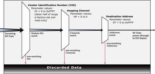
4 Shutdown Voltage: Default: 3.4 Volts. The BRB900 Transmitter contains battery monitoring circuitry and will shutdown the transmitter if the voltage falls below the programmed level. Store Interface: Approx 1200 data points can be saved in the on board non-volatile memory. Data is stored every N seconds, in this case 1. Transmit Interval: the $BRBTX data packet is transmitter every N seconds, in this case, 5. Wrap Mem: Flight data will be continuously logged to memory, wrapping around to the beginning when the end is reached. If this box is not checked, data logging will stop when the end of memory is reached. Enable NMEA: The raw NMEA sentences from the GPS are echoed onto the RF Data Link (this option should bot should not be enabled) Enable $BRBTX: The $BRBTX sentence is sent on the RF data link every N seconds as indicated by the Transmit Interval Read: Read the device parameters. Make sure to select the proper COM port. Always being a programming session with a Read command Write: Write the device parameters Read Flash: Read the contents of the flight data logged in non-volatile memory. Clear Flash: Clear the non-volatile memory. It is recommended to clear the memory before e each flight. Go: Exit command mode. 9. Networking Parameters In addition to the unique identifier contained in the $BRBTX sentence, the transmitter and receiver use several identification parameters that determine which RF packets will be decoded by the receiver. These include a Vendor ID, Hopping Channel, and Destination address. By default, each receiver is programmed to recognize up to 4 different destination addresses. Each transmitter must have a matching Vendor ID, Hopping Channel and group of destination addresses. It is possible to modify the networking parameters of the RF transmitter. This functionality is enabled by invoking the BRB900 Communicator with the -rf command line option. The parameters of the receiver can be made using the X-CTU software from digi.com These parameters can be modified so that all packets matching the Vendor ID and Hopping Channel are displayed. Additionally the Vendor ID and Hopping Channel can be modified to match other vendors. Default Settings for Address Parameters: Hopping Channel (ATHP): The default hopping channel for the BRB900 transmitter and receiver is 5, and should not be changed. Address Mask (ATMK): The default address mask is 0xFFFF and should not be changed. Destination Address (ATDT): Each transmit/receive pair is shipped with a unique/matching destination address. In order for the Receiver to decode the transmitter packets, the Destination addresses must match. If you purchase additional transmitters, you can change the Destination Address to match your existing receiver. Vendor Identification (ATID): The default Vendor ID is 0x3BEE, and should not be changed. UPDATE: The update button will modify the BRB900 Transmitter parameters. Use extreme caution when modifying these settings
5
6 *The RF parameters cannot be modified while the transmitters is installed in the base level transmitter 10. Special Sentence Format $BRBTX BigRedBee Summary Information $BRBTX, ID0001,*,033618, N, W,04,2.69,012345,1.24,2F0 Where: $BRBTX BigRedBee Summary Packet ID0001 Unique identifier string * BRB Status Flag fix taken at UTC Time N Latitude 34 degrees minutes North W Longitude 123 degrees W minutes West 04 4 satellites user to compute position 2.69 HDOP Altitude in Meters or Feet 1.24 VDOP 2F0 Raw A/D conversion of onboard battery voltage 11. LCD Display When the power switch is turned on, the LCD will display the following information: The firmware version (V0.01) and the battery voltage of the receiver are displayed. The BRB-LCD can be configure to display the information from the $GPGGA sentence, or the $BRBTX sentence. Switching between modes is accomplished by holding the configuration button while the unit is powered on. x B R B V x x v B A T = B R B x x B i g R e d B e e, L L C x If the configuration button is held when power is applied, the NMEA mode will be toggled. x B R B V x x v B A T = N M E A x x B i g R e d B e e, L L C x
7 The 16x3 line LCD display contains the following information when decoding the $GPGGA NMEA sentence x * H x x x x S 4 x The 16x3 line LCD display contains the following information when decoding the $BRBTX Summary sentence before the GPS has locked. Note that the battery voltage and # of satellites are valid. x -,,,,,,,,,,,,, x x,,,,,,,,,,,,,, x x,,,,,,, S 0 B x

8 The 16x3 line LCD display contains the following information when decoding the $BRBTX Summary sentence. x * H x x V x x S 4 B x Altitude in this mode is MSL. If the configuration button is held, the LCD receiver will lock in the currently altitude as the base altitude, and report all future altitudes as AGL. Negative altitudes will be displayed as 0. x * H x x V x x a 2 3 S 4 B x *: Status Character: * Latitude: Longitude: Altitude: H269 Horizontal Dilution of Precision (HDOP): 2.69 V909 Vertical Dilution of Precision (VDOP) Time of Day (Seconds only): 23 S4 Number of satellites in view: 4 B395 Voltage of Battery on Transmitter 3.95V 12. BigRedBee USB Interface and Charger The BigRedBee USB interface integrates the functionality of two separate devices; a USB data interface, and a single cell lithium poly battery charger. The charger and programming interface functions should not be used at the same time. When programming the device, the battery must be used to provide power. Power is NOT provided via the USB interface. Do not attempt to charge the battery and modify the device parameters at the same time Single Cell Lithium Poly Charger Plug the USB cable into the USB interface board and connect to your computer s USB port. Plug the battery into the three pin connector. The LED will remain on while the battery is charging, and turn off once it is fully charged. Charge rate is 100 milliamps per hour. The battery charger function is independent of the data interface. The battery WILL NOT CHARGE unless it is connected directly to the 3-pin header on the USB / charger interface USB Data Interface
9 USB Apply power to the transmitter. Plug the USB cable into the USB interface board and connect to your computer s USB port. If this is the first time you have used this type of USB interface, Windows will need to install the drivers for it. Once Windows has recognized the device, plug the 5-pin connector on the USB adapter into the Beeline transmitter. Now you can use the BeeLine Communicator to modify the device parameters. Make sure to select the proper COM port Drivers are located here: 13 Misc Info Transmitter Dimensions: 1.25 wide x 2.85 long, excluding transmit antenna. Antenna: Reverse Polarity SMA, 3dbi gain approx 4.25 long GPS Module: u-blox Neo 6Q. Altitude and speed may exceed 18,000 meters or 515 meters/second, but not both. RF Transmitter: 250 mw 900 Mhz Spread Spectrum. Receive Current : 115mA Transmit Current: 315mA Power supply: Single cell Lithium Poly battery (3.5 to 4.2 Volts) 14 Board Description and Connectors Turning on the Transmitter: Plug battery J3 into board J2 Programming: RF Plug J4 into J1, aligning pin 1. Power must be applied as described in section 14.2 while programming Battery Charging Plug J3 into J5, and the USB connector into the PC using the supplied cable. connectors are keyed, and can only be installed in one direction. The GPS J2 J1 J4 J3 J5
Featherweight GPS Tracker User s Manual June 16, 2017
 Featherweight GPS Tracker User s Manual June 16, 2017 Hardware Configuration and Installation The dimensions for the board are provided below, in inches. Note that with the antenna installed, the total
Quick Start. Precis-BX305. Precise GNSS RTK Board.
 Quick Start Precis-BX305 Precise GNSS RTK Board www.tersus-gnss.com December, 2016 Quick Start Guide of Precis-BX305 This quick start guide provides the basic information needed to set up and use Precis-BX305
BeeLine TX User s Guide V1.1c 4/25/2005
 BeeLine TX User s Guide V1.1c 4/25/2005 1 Important Battery Information The BeeLine Transmitter is designed to operate off of a single cell lithium polymer battery. Other battery sources may be used, but
instruction manual for Open LRS New Generation
 instruction manual for Open LRS New Generation Table of contents 1. Important warnings 2. Hardware Overview 3 2.1 DTF UHF 4 Channel 4 2.2 HobbyKing RX 5 3. Instructions 3.1 Basic functions 6 3.2 Flashing
GPS Receiver. User s Guide. Dec Rev. A
 GR-213U GPS Receiver User s Guide Dec. 25 2005 Rev. A Technology, Inc. 1F.No 30, R&D Rd. II. Hsinchu City, Science-based Industrial Park Taiwan Phone: +886-3-6687000 Fax: +886-3-6687111 E-Mail: info@holux.com.tw
era, eric, era-lora, eric-lora & eric-sigfox Evaluation Board with GNSS
 This board can be used for the evaluation and range testing of the following LPRS RF Modules: era400, era900, eric4, eric9, era-lora, eric-lora and eric-sigfox. The board is provided with a u-blox GNSS
Part Number Weblink for the part Description Unit Price. Hardware interfacing to the Freescale 9S12C32 MCU on board the CSM-12C32 module
 Global Positioning System Modules This section shows how to connect a GPS module to the CSM-12C32 module and provide several C functions for capturing the latitude, longitude, and UTC time information.
----STAR S86 GPS Receiver. User Guide. SOUTH CO., Ltd.
 ----STAR S86 GPS Receiver User Guide SOUTH CO., Ltd. www.southsurveying.com Sales@SOUTHsurveying.com 2 CONTENTS Chapter 1 Introduction... 1 STAR S86 GPS - System Summary... 1 Technical Specification...
Micro Fox PicCon Manual
 Micro Fox PicCon Manual Version 0.61 The Micro Fox PicCon (MF PC) is a 700mW fox hunting/hidden transmitter hunt transceiver. It can be configured and remotely controlled via DTMF tones, and also be configured
FOD Transmitter User s Guide
 FOD Transmitter User s Guide Rev 5, 05/21/2014 AVID Technologies, Inc. FOD Transmitter User s Guide Page 2 General Description The AVID FOD (Foreign Object Detection) Transmitter is a standard WPC Qi V1.1
Quick Start. Tersus GNSS Center. Configuration Tools for Tersus GNSS RTK Systems.
 Quick Start Tersus GNSS Center Configuration Tools for Tersus GNSS RTK Systems www.tersus-gnss.com July, 2016 1. Quick Start Guide of Tersus GNSS Center This quick start guide provides the basic information
SonoLab Echo-I User Manual
 SonoLab Echo-I User Manual Overview: SonoLab Echo-I is a single board digital ultrasound pulse-echo solution. The system has a built in 50 volt high voltage generation circuit, a bipolar pulser, a transmit/receive
DragonLink Advanced Transmitter
 DragonLink Advanced Transmitter A quick introduction - to a new a world of possibilities October 29, 2015 Written by Dennis Frie Contents 1 Disclaimer and notes for early release 3 2 Introduction 4 3 The
GM-270. CF GPS Receiver. User s Guide
 GM-270 CF GPS Receiver User s Guide Jul 05, 2002 TABLE OF CONTENTS 1. Introduction.. 3 1.1 Overview.. 3 1.2 Features.. 3 2. Brief Information. 5 2.1 Hardware Interface 5 2.2 Software Interface 6 3. Functional
Lifetime Power Energy Harvesting Development Kit for Wireless Sensors User s Manual - featuring PIC MCU with extreme Low Power (XLP) Technology
 Technology") P2110-EVAL-01 Lifetime Power User s Manual - featuring PIC MCU with extreme Low Power (XLP) Technology Overview The Lifetime Power is a complete demonstration and development platform for creating battery-free
P2110-EVAL-01 Lifetime Power User s Manual - featuring PIC MCU with extreme Low Power (XLP) Technology Overview The Lifetime Power is a complete demonstration and development platform for creating battery-free
Datasheet of stand-alone GPS smart antenna module, LS20037
 Product name Description Version LS20037 Stand-alone GPS smart antenna module/mtk,9600bps 0.9 (Preliminary) Datasheet of stand-alone GPS smart antenna module, LS20037 1 Introduction LS20037 is a complete
GPS Engine Board FGPMMOSL3
 GPS Engine Board with MTK Chipset FGPMMOSL3 The document is the exclusive property of and should not be distributed, reproduced, or any other format without prior Copyright 2007 All right reserved. 1 History
GPS-41MLR GPS-41MLF. GPS Receiver Module GPS-41ML. Fast Acquisition Enhanced Sensitivity 12 Channel GPS Sensor Module FEATURES. Ordering Information
 GPS-41ML Fast Acquisition Enhanced Sensitivity 12 Channel GPS Sensor Module FEATURES 12 parallel channel GPS receiver 4100 simultaneous time-frequency search bins SBAS (WAAS, EGNOS) support High Sensitivity:
SV613 USB Interface Wireless Module SV613
 USB Interface Wireless Module SV613 1. Description SV613 is highly-integrated RF module, which adopts high performance Si4432 from Silicon Labs. It comes with USB Interface. SV613 has high sensitivity
ThunderBolt Display. by Adam Maurer, VK4GHZ
 ThunderBolt Display by Adam Maurer, VK4GHZ Overview ThunderBolt Display is a stand-alone microprocessor-controlled LCD specifically for Trimble s ThunderBolt Disciplined Clock, providing a comprehensive
FOD Transmitter User s Guide
 FOD Transmitter User s Guide Rev 4, 07/18/2013 AVID Technologies, Inc. FOD Transmitter User s Guide Page 2 General Description The AVID FOD (Foreign Object Detection) Transmitter is a standard WPC Qi V1.1
GPS SMART ANTENNA (GWG4287SX)
") GPS SMART ANTENNA (GWG4287SX) SiRFSTARIII /LPx Specifications are subject to change without notice KOREA ELECTRIC TERMINAL CO., LTD. All right reserved http://www.ket.com 1. Introduction 1.1 Over view
GPS SMART ANTENNA (GWG4287SX) SiRFSTARIII /LPx Specifications are subject to change without notice KOREA ELECTRIC TERMINAL CO., LTD. All right reserved http://www.ket.com 1. Introduction 1.1 Over view
VBRC 5. Radio Communicator. Installer Manual
 VBRC 5 Radio Communicator Installer Manual 10 / 10 / 2013 CONTENT 1. INTRODUCTION...3 2. SYSTEM STRUCTURE...3 3. SYSTEM PROGRAMMING WITH PC SOFTWARE...5 4. TROUBLESHOOTING...6 5. FIRMWARE UPGRADE...7 6.
Quick-Start Guide. M7 Series DATA RADIO MODEM
 Quick-Start Guide M7 Series DATA RADIO MODEM Raveon Technologies Corporation 2461 Impala Drive Carlsbad, CA 92010 - USA Phone +1-760-444-5995 www.raveon.com www.ravtrack.com 1 This is a quick-start guide
Getting Started with TrangoLink
 Getting Started with TrangoLink Overview: TrangoLink allows you to configure and monitor your EAGLE PLUS, FALCON, or PTZ-900 transmitters and receivers. On the EAGLE PLUS and FALCON transmitters, you can
Revision WI.232FHSS-25-FCC-R and RK-WI.232FHSS-25-FCC-R USER S MANUAL
 Revision 1.0.3 WI.232FHSS-25-FCC-R and RK-WI.232FHSS-25-FCC-R USER S MANUAL RADIOTRONIX, INC. WI.232FHSS-25-FCC-R/ RK-WI.232FHSS-25-FCC-R USER S MANUAL Radiotronix 905 Messenger Lane Moore, Oklahoma 73160
RC Altimeter #2 BASIC Altitude data recording and monitoring system 3/8/2009 Page 2 of 11
 Introduction... 3 How it works... 3 Key features... 3 System requirements... 3 Hardware... 4 Specifications... 4 Using the RC Altimeter #2 BASIC module... 5 Powering the module... 5 Mounting the module...
32-channel GPS Engine Board SmartAntenna
 32-channel GPS Engine Board SmartAntenna with MTK Chipset The document is the exclusive property of and should not be distributed, reproduced, or any other format without prior permission of Specifications
MiniGMouse-PS2. User Manual. Document : Datasheet Model # : GPS Date : 01-Jan -10
 Document : Datasheet Model # : GPS - 1267 Date : 01-Jan -10 MiniGMouse-PS2 User Manual Rhydo Technologies (P) Ltd. (An ISO 9001:2008 Certified R&D Company) Golden Plaza, Chitoor Road, Cochin 682018, Kerala
Micro-Trak All-In-One APRS Transmitter
 Micro-Trak All-In-One APRS Transmitter Hardware version 1.1, Manual Version 1.1 The MT-AIO is a self-contained, water resistant APRS transmitter/gps receiver designed for portable use. The MT-AIO is computer
VBRC 4. Radio Communicator. Installer Manual
 VBRC 4 Radio Communicator Installer Manual 17 December 2014 CONTENT 1. INTRODUCTION...3 2. SYSTEM STRUCTURE...3 3. SYSTEM PROGRAMMING WITH PC SOFTWARE...5 4. TROUBLESHOOTING...6 5. FIRMWARE UPGRADE...7
GPS-G5 User s Manual
 GPS-G5 User s Manual Contents Using the GPS... 1 Description...1 Electrical Connections...2 Mounting...3 GPS Configuration...3 GPS Operation...3 Logging Device Configuration...4 Data Analysis...5 Specifications...
Analog & Digital I/O Wireless Bridge USERS MANUAL R02
 Analog & Digital I/O Wireless Bridge USERS MANUAL R02 Contents Overview... 3 Specifications... 3 Absolute Maximum Ratings... 3 Recommended Operating Conditions... 3 Performance... 4 Power Requirements...
EzOSD Manual. Overview & Operating Instructions Preliminary. April ImmersionRC EzOSD Manual 1
 EzOSD Manual Overview & Operating Instructions Preliminary. April 2009 ImmersionRC EzOSD Manual 1 Contents Overview... 3 Features... 3 Installation... 3 1. Installation using an ImmersionRC camera and
Tarocco Closed Loop Motor Controller
 Contents Safety Information... 3 Overview... 4 Features... 4 SoC for Closed Loop Control... 4 Gate Driver... 5 MOSFETs in H Bridge Configuration... 5 Device Characteristics... 6 Installation... 7 Motor
GPS Evaluation Kit EVA1035-H
 GPS Evaluation Kit EVA1035-H A Description of the Evaluation Board for Vincotech s GPS Receiver / Smart Antenna Module A1035-H User s Manual Version 1.0 Hardware Revision 01 Revision History Rev. Date
1 What s in the shipping package?
 SST 900B 900 MHz RS 232/RS 485 Wireless Modem Quick Start Guide 1 What s in the shipping package? SST-900B Wireless Modem CA-0910 Quick Start CD 3dBi 900M Hz Antenna Guide 2 External switch introduction
DEVICE CONFIGURATION INSTRUCTIONS. WinFrog Device Group:
 WinFrog Device Group: Device Name/Model: Device Manufacturer: Device Data String(s) Output to WinFrog: WinFrog Data String(s) Output to Device: WinFrog Data Item(s) and their RAW record: GPS NMEA GPS (Sercel)
1090i. uavionix Ping1090i Transceiver QUICK START GUIDE
 1090i uavionix Ping1090i Transceiver QUICK START GUIDE Install 1 Install the uavionix Ping App from the Apple App Store or Google Play. Search for uavionix Ping Installer or use the QR codes below. Connect
SMARTALPHA RF TRANSCEIVER
 SMARTALPHA RF TRANSCEIVER Intelligent RF Modem Module RF Data Rates to 19200bps Up to 300 metres Range Programmable to 433, 868, or 915MHz Selectable Narrowband RF Channels Crystal Controlled RF Design
66-Channel GPS Module GP-3711
 66-Channel GPS Module with MTK Chipset GP-3711 Low power consumption version 1 History Date Rev. Description 2013/12/31 A00 First Release 2 Description The GP-3711 is a ROM-based mini GPS module which
CONDOR C1919 GPS RECEIVER MODULE technical notes GENERAL OVERVIEW
 CONDOR C1919 GPS RECEIVER MODULE TECHNICAL HIGHLIGHTS Receiver: GPS L1 frequency (17. MHz), C/A code, -channel continuous tracking NMEA output and input: serial port On-board low noise amplifier GENERAL
ProLink Radio. 900 MHz SDI-12 Data Radio Scienterra Limited. Version A-0x0C-1-AC 20 October 2009
 ProLink Radio 900 MHz SDI-12 Data Radio Scienterra Limited Version A-0x0C-1-AC 20 October 2009 For sales inquiries please contact: ENVCO Environmental Collective 31 Sandringham Rd Kingsland, Auckland 1024
IT-24 RigExpert. 2.4 GHz ISM Band Universal Tester. User s manual
 IT-24 RigExpert 2.4 GHz ISM Band Universal Tester User s manual Table of contents 1. Description 2. Specifications 3. Using the tester 3.1. Before you start 3.2. Turning the tester on and off 3.3. Main
Long Range Wireless OSD 5.8G FPV Transmitter
 Long Range Wireless OSD 5.8G FPV Transmitter Built-in 10 Axis AHRS + MAVLINK + 600mW Support all flight controller and GPS 1 / 14 User's Guide Catalogue Product Instruction 3 Features 3 Specifications.4
Stensat Transmitter Module
 Stensat Transmitter Module Stensat Group LLC Introduction The Stensat Transmitter Module is an RF subsystem designed for applications where a low-cost low-power radio link is required. The Transmitter
900 MHz. Frequency Hopping RS-485 Master/Slave auto-sensing radio interface.
 MDR210A-485 900 MHz. Frequency Hopping RS-485 Master/Slave auto-sensing radio interface. Black Box Corporation Lawrence, PA - http://www.blackbox.com - Ph 877-877-BBOX - Fax 724-746-0746 Table of Contents
Contents. Chapter 1 Brief Introduction of K9 series Chapter 2 K9 series mainframe The appearance of mainframe Interface...
 Contents Chapter 1 Brief Introduction of K9 series... 1 Chapter 2 K9 series mainframe... 2 2.1 The appearance of mainframe... 2 2.2 Interface... 2 2.3 The installation of battery... 3 2.4 Guiding light
SmartRadio Transmitter / Receiver
 Easy to use Radio Transmitter & Receivers AM Radio Hybrid Technology Supports Data or Telemetry communications Simple CMOS/TTL Data Interface Automatic data encryption / decryption Host Interface up to
GPS-41EBR GPS-41EBF. GPS Receiver Module GPS-41EB. Fast Acquisition Enhanced Sensitivity 12 Channel GPS Sensor Module FEATURES. Ordering Information
 FEATURES 12 parallel channel GPS receiver 4000 simultaneous time-frequency search bins SBAS (WAAS, EGNOS) support High Sensitivity: -140dBm acquisition sensitivity -150dBm tracking sensitivity Fast Acquisition:
Dragon. manual version 1.7
 Dragon manual version 1.7 Contents DRAGON TOP PANEL... 2 DRAGON STARTUP... 2 DRAGON STARTUP SCREEN... 2 DRAGON INFO SCREEN... 3 DRAGON MAIN SCREEN... 3 TURNING ON A TRANSMITTER... 4 CHANGING MAIN SCREEN
TX CONTROLLER Model EM-IP Quick Start Guide
 TX CONTROLLER Model EM-IP Quick Start Guide 860 boul. de la Chaudière, suite 200 Québec (Qc), Canada, G1X 4B7 Tel.: +1 (418) 877-4249 Fax: +1 (418) 877-4054 E-Mail: gdd@gdd.ca Web site: www.gdd.ca Visit
Big Blue Mars Final Report
 Big Blue Mars Final Report Member Names Kyle Hart Dale McClure Michael McEwen Contact Information hartman1000@hotmail.com michaelmce@yahoo.com dale.mcclure@uky.edu 2006-04-02 Faculty Advisor Dr. Bill Smith
Arduino Arduino RF Shield. Zulu 2km Radio Link.
 Arduino Arduino RF Shield RF Zulu 2km Radio Link Features RF serial Data upto 2KM Range Serial Data Interface with Handshake Host Data Rates up to 38,400 Baud RF Data Rates to 56Kbps 5 User Selectable
GPS Firmware A1080 A description of the standard NMEA GPS firmware provided on Tyco Electronics GPS module A1080 User s Manual Version 3.
 GPS Firmware A description of the standard NMEA GPS firmware provided on Tyco Electronics GPS module User s Manual Version 3.0 This page was intentionally left blank. Revision History Revision History
Will only send Status Text until GPS Lock! Format of Status Text: Status Text Altitude Volts Temp X AVRT5 (version)
") AP510 / AVRT5 Documentation Based upon firmware and configuration version(s) 20151031 (development build) Author: Mark Cheavens KC5EVE Version: 20151031 1.1 Quick Start: Power Button Uses: Firmware Update
AP510 / AVRT5 Documentation Based upon firmware and configuration version(s) 20151031 (development build) Author: Mark Cheavens KC5EVE Version: 20151031 1.1 Quick Start: Power Button Uses: Firmware Update
Key Modules For Your Success. ANTARIS 4 SuperSense. GPS Module. User s Manual Ver 展得國際有限公司
 ANTARIS 4 SuperSense GPS Module User s Manual Ver 1.01 Item Date New Release Information In Charge 1 2006/06/06 New released. Harry Lee 2 Contents 1. INTRODUCTION... 4 1.1 OVERVIEW. 4 1.2 MAIN FEATURES...
IEFIS GPS manual Applicable to iefis G3 including Lite versions Firmware or later
 IEFIS GPS manual Applicable to iefis G3 including Lite versions Firmware 1.0.3.5 or later Page 1 Table of Contents General...3 GPS sources...3 Internal GPS...3 NMEA GPS...3 ARINC GPS...3 CAN based GPS...3
GPS Evaluation Kit EVA1084-A
 GPS Evaluation Kit EVA1084-A A Description of the Evaluation Board for Vincotech s GPS Receiver Modules A1084-A/-B User s Manual Version 1.0 Hardware Revision 01 V1.0 Jan-09 User s Manual Page 1 of 18
Four Simple Steps to Get Started
 Four Simple Steps to Get Started This guide provides an overview of the important features and instructions for how to set up and operate the Spectra Precision SP90m GNSS receiver. 1. Unpack and check
RM24100A. Introduction. 1 Features. 2.4GHz 100mW RS232 / RS485 / RS422 DSSS Radio Modem (IEEE compliant) Operating Manual English 1.
 Operating Manual English 1.") RM24100A 2.4GHz 100mW RS232 / RS485 / RS422 DSSS Radio Modem (IEEE 802.15.4 compliant) Operating Manual English 1.03 Introduction The RM24100A radio modem acts as a wireless serial cable replacement and
RM24100A 2.4GHz 100mW RS232 / RS485 / RS422 DSSS Radio Modem (IEEE 802.15.4 compliant) Operating Manual English 1.03 Introduction The RM24100A radio modem acts as a wireless serial cable replacement and
Revision Date: 6/6/2013. Quick Start Guide
 Revision Date: 6/6/2013 Quick Start Guide Important Notice Copyright 2013Frontline Test Equipment. All rights reserved. i Important Notice Table of Contents Purpose 1 Minimum Hardware Requirements 1 Internet
CDR-915 Data Radio Module INTEGRATOR S GUIDE
 CDR-915 Data Radio Module Coyote DataCom, Inc. 3941 Park Drive, Suite 20-266, El Dorado Hills, CA 95762 Tel. 916-933-9981 Fax 916-913-0951 www.coyotedatacom.com TABLE OF CONTENTS General Information and
MicroFox2 Manual. Version 0.5 August 28, 2017
 Overview The Byonics MicroFox2 (MF2) is a small, 500mW, frequency agile 2-meter transceiver designed for hidden transmitter hunts, also called T-hunts, foxhunts, and ARDF. It is based on the Byonics MicroFox-PicCon,
EM-406 GPS RECEIVER ENGINE BOARD PRODUCT GUIDE
 EM-406 GPS RECEIVER ENGINE BOARD PRODUCT GUIDE GlobalSat Technology Corporation 16, No.186,Chien 1 Road, 235Chung Ho City,Taipei Hsien, Taiwan,R.O.C. www.globalsat.com.tw USGlobalSat, Inc. (USA Sales)
RM24100D. Introduction. 1 Features. 2.4GHz 100mW RS232 / RS485 / RS422 DSSS Radio Modem (IEEE compliant) Operating Manual English 1.
 Operating Manual English 1.") RM24100D 2.4GHz 100mW RS232 / RS485 / RS422 DSSS Radio Modem (IEEE 802.15.4 compliant) Operating Manual English 1.03 Introduction The RM24100D radio modem acts as a wireless serial cable replacement and
RM24100D 2.4GHz 100mW RS232 / RS485 / RS422 DSSS Radio Modem (IEEE 802.15.4 compliant) Operating Manual English 1.03 Introduction The RM24100D radio modem acts as a wireless serial cable replacement and
GPS Application. Global Positioning System. We provide GPS module ODM / OEM service, any GPS receiver you want, we can provide customized services.
 GPS Application Global Positioning System We provide GPS module ODM / OEM service, any GPS receiver you want, we can provide customized services. www.win-tec.com.tw sales@win-tec.com.tw GNSS Receiver WGM-303
DR-TRC105-EV Evaluation Kit. User s Guide
 DR-TRC105-EV Evaluation Kit User s Guide DR-TRC105-304-EV DR-TRC105-315-EV DR-TRC105-345-EV DR-TRC105-372-EV DR-TRC105-390-EV DR-TRC105-403-EV DR-TRC105-434-EV DR-TRC105-450-EV 2010-2015 by Murata Electronics
SIMREX Corporation Your Trusted Wireless Solution Provider
 SIMSYNC Instruction Manual Traffic Controller Time Synchronization System Firmware Release 1.7 SIMREX MAN.SIMSYNC, Rev 8.0 MARCH 2006 Your Trusted Wireless Solution Provider www.simrex.com Introduction
Configuration Program for OZ4HZ Version 2 Tracker (rev ).
.") Configuration Program for OZ4HZ Version 2 Tracker (rev. 2008-12-08). The tracker is configured with a Windows program witch can be downloaded from the website. www.aargang64.dk/aprs Use a standard null-modem
Configuration Program for OZ4HZ Version 2 Tracker (rev. 2008-12-08). The tracker is configured with a Windows program witch can be downloaded from the website. www.aargang64.dk/aprs Use a standard null-modem
DJT RC Transmitter Module 2.4 GHz Two-Way Series
 Manual Rev.0.1-5.05.201 2 made by David LABURTHE dlaburthe@free. fr DJT RC Transmitter Module 2.4 GHz Two-Way Series U S E R ' S G U I D E FrSky Electronic Co., Ltd - No. 1, Huize Road, Wuxi, 21 4081,
XMT-G (GPS Synchronized) TRANSMITTER CONTROLLER MANUAL
 TRANSMITTER CONTROLLER MANUAL") XMT-G (GPS Synchronized) TRANSMITTER CONTROLLER MANUAL Zonge International, Inc. 3322 East Fort Lowell Road, Tucson, AZ 85716 USA Tel:(520) 327-5501 Fax:(520) 325-1588 Email:zonge@zonge.com Note: This
XMT-G (GPS Synchronized) TRANSMITTER CONTROLLER MANUAL Zonge International, Inc. 3322 East Fort Lowell Road, Tucson, AZ 85716 USA Tel:(520) 327-5501 Fax:(520) 325-1588 Email:zonge@zonge.com Note: This
Wireless Temp/Setpoint & Override Room Transmitter
 Overview The BAPI Wireless Combination Transmitter measures the room temperature and relative humidity and transmits the data at 418MHz or 433MHz RF to a receiver. Temperature setpoint and override button
HURRICANE Radio Modem. FULL DUPLEX Radio MODEM
 FULL DUPLEX Radio MODEM Direct Cable Replacement Range 2KM RS232 / RS485 / USB Host Data Rates up to 38,400 Baud RF Data Rates to 115200Kbps Waterproof IP68 Enclosure 8 User Selectable Channels CE Compliant
GPS (GLOBAL POSITIONING SYSTEM)
") GPS (GLOBAL POSITIONING SYSTEM) What is GPS? GPS, standing for Global Positioning System, is becoming common nowadays. Following is a brief introduction. The American Defense Department developed GPS originally
GPS (GLOBAL POSITIONING SYSTEM) What is GPS? GPS, standing for Global Positioning System, is becoming common nowadays. Following is a brief introduction. The American Defense Department developed GPS originally
FGPMMOPA6B. [Fully pin compatible with FGPMMOPA6]
![FGPMMOPA6B. [Fully pin compatible with FGPMMOPA6]](/thumbs/87/95702517.jpg "FGPMMOPA6B. [Fully pin compatible with FGPMMOPA6]") 66-channel GPS Engine Board Antenna Module FGPMMOPA6B with MTK Chipset [Fully pin compatible with FGPMMOPA6] The document is the exclusive property of and should not be distributed, reproduced, or any
66-channel GPS Engine Board Antenna Module FGPMMOPA6B with MTK Chipset [Fully pin compatible with FGPMMOPA6] The document is the exclusive property of and should not be distributed, reproduced, or any
EM-401. GPS ENGINE BOARD with Active Antenna PRODUCT GUIDE. Globalsat Technology Corporation (Taiwan)
") EM-401 GPS ENGINE BOARD with Active Antenna PRODUCT GUIDE Globalsat Technology Corporation (Taiwan) www.globalsat.com.tw USGlobalSat, Inc. (USA) www.usglobalsat.com Page 1 of 1 EM-401 GPS BOARD with Active
EM-401 GPS ENGINE BOARD with Active Antenna PRODUCT GUIDE Globalsat Technology Corporation (Taiwan) www.globalsat.com.tw USGlobalSat, Inc. (USA) www.usglobalsat.com Page 1 of 1 EM-401 GPS BOARD with Active
GPS Module AGP3363. Product Datasheet & Design Guide <V1.0>
 GPS Module AGP3363 Product Datasheet & Design Guide AMOD Technology Co.,LTD Subject to changes in technology, design and availability URL: http://www.amod.com.tw Add. 8F., No. 46, Lane 10, Jihu
GPS/GNSS Receiver Module
 GPS/GNSS Receiver Module 1. Product Information 1.1 Product Name: YIC91612IEB9600 1.2 Product Description: YIC91612IEB9600 is a compact, high performance, and low power consumption GNSS engine board which
RM24100A. *Maximum transmit power output levels and local radio frequency regulator bodies must be obeyed in the country of operation.
 RM24100A 2.4GHz 100mW RS232 / RS485 / RS422 DSSS Radio Modem (IEEE 802.15.4 compliant) Operating Manual English 1.02 Introduction The RM24100A radio modem acts as a wireless serial cable replacement and
Global Navigation Satellite System for IE 5000
 Global Navigation Satellite System for IE 5000 Configuring GNSS 2 Information About GNSS 2 Guidelines and Limitations 4 Default Settings 4 Configuring GNSS 5 Configuring GNSS as Time Source for PTP 6 Verifying
KanAtoN 1 / 3 AIS Transponder. Installation Manual
 Orolia S.A.S. Z.I. des Cinq Chemins 56520 GUIDEL - FRANCE Telephone: +33 (0)2 97 02 49 49 Fax: +33 (0)2 97 65 00 20 Web : http://www.mcmurdomarinesystems.com An Orolia Group Business DATE : 20/072012 KanAtoN
GR-87 GPS Receiver Module
 GR-87 GPS Receiver Module 1. Main Feature Build on high performance SiRF StarIII chipset. Average Cold Start time and under 45 seconds. Low power consumption 20 channels All-in-View tracking. 200,000+
RTKWARE UBR1 Technical Datasheet. ver1.1 (29/04/2015)
") RTKWARE UBR1 Technical Datasheet ver1.1 (29/04/2015) Table of Contents Table of Contents... 2 Overview... 3 Key-Features... 3 Applications... 3 Functional diagrams... 4 Power Distribution... 4 Data...
RTKWARE UBR1 Technical Datasheet ver1.1 (29/04/2015) Table of Contents Table of Contents... 2 Overview... 3 Key-Features... 3 Applications... 3 Functional diagrams... 4 Power Distribution... 4 Data...
FieldGenius Technical Notes GPS Differential Corrections
 FieldGenius Technical tes GPS Differential Corrections Introduction The accuracy requirement of survey grade or mapping grade GPS applications for real time positioning requires the use of differential
ExpoM - ELF User Manual
 ExpoM - ELF User Manual Version 1.4 ExpoM - ELF User Manual Contents 1 Description... 4 2 Case and Interfaces... 4 2.1 Overview... 4 2.2 Multi-color LED... 5 3 Using ExpoM - ELF... 6 3.1 Starting a Measurement...
XLR PRO Radio Frequency (RF) Modem. Getting Started Guide
 Modem. Getting Started Guide") XLR PRO Radio Frequency (RF) Modem Getting Started Guide XLR PRO Radio Frequency (RF) Modem Getting Started Guide 90002203 Revision Date Description A September 2014 Initial release. B March 2014 Updated
XLR PRO Radio Frequency (RF) Modem Getting Started Guide XLR PRO Radio Frequency (RF) Modem Getting Started Guide 90002203 Revision Date Description A September 2014 Initial release. B March 2014 Updated
Complete 2.4 GHz RF Transceiver Module with Built-In RFDP8 Application Protocol Part Numbers RFD21733, RFD21735, RFD21737, RFD21738, RFD21739
 Complete 2.4 GHz RF Transceiver Module with Built-In Application Protocol Part Numbers,,,, Optional Configuration For use with External Antenna 15mm x 15mm (0.600 inch x 0.600 inch) / is a complete, READY-TO-USE
BVS RHINO PC INTERFACE SOFTWARE
 BVS RHINO PC INTERFACE SOFTWARE INSTALLATION Copy the file "rhino.exe" from the supplied disk to a directory on the hard drive of the computer. PC SETTINGS PC COM Port 1 must be set as follows using the
SRT Marine Technology. LD2342 V1.4 Page 1 of 22
 LD2342 V1.4 Page 1 of 22 LD2342 V1.4 Page 2 of 22 2 LD2342 V1.4 Page 3 of 22 GENERAL WARNINGS All marine Automatic Identification System (AIS) units utilise a satellite based system such as the Global
Applications: FM wireless audio, USB PC audio broadcasting, wireless microphones, maternal and child care.
 Product Description 1: The use of advanced digital audio signal processing (DSP) technology and FM modulation phase-locked loop (PLL) to make sound more realistic, more stable performance, long working
RM24100D. Introduction. Features. 2.4GHz 100mW RS232 / RS485 / RS422 DSSS Radio Modem (IEEE compliant) Operating Manual English 1.
 Operating Manual English 1.") RM24100D 2.4GHz 100mW RS232 / RS485 / RS422 DSSS Radio Modem (IEEE 802.15.4 compliant) Operating Manual English 1.09 Introduction The RM24100D radio modem acts as a wireless serial cable replacement and
RM24100D 2.4GHz 100mW RS232 / RS485 / RS422 DSSS Radio Modem (IEEE 802.15.4 compliant) Operating Manual English 1.09 Introduction The RM24100D radio modem acts as a wireless serial cable replacement and
RV-M7 GX. Quick-Start Guide
 RV-M7 GX G P S T r a n s p o n d e r Quick-Start Guide Version C0 February 2010 RV-M7 GX RV-M7 GX WX Raveon Technologies Corporation 990 Park Center Drive, Suite C Vista, CA 92081 www.ravtrack.com www.raveontech.com
RV-M7 GX. Quick-Start Guide Version B0 June 2008 RV-M7-UC-GX RV-M7-UC-GX-WX
 RV-M7 GX U H F G P S T r a n s c e i v e r Quick-Start Guide Version B0 June 2008 RV-M7-UC-GX RV-M7-UC-GX-WX Raveon Technologies Corporation 2780 La Mirada Drive, Suite C Vista, CA 92081 www.raveontech.com
Ct-G551. Connectec. SiRF V GPS Module. Specifications Sheet V0.1. Features: Ct-G551 V0.1 Specification Sheet
 SiRF V GPS Module Ct-G551 Specifications Sheet V0.1 Features: SiRF StarV ultra low power chipset GPS, GLONASS, Galileo and SBAS reception for high GNSS availability and accuracy Compact module size for
Release 0.3. Rolling Thunder Technical Reference Manual
 Release 0.3 Rolling Thunder Technical Reference Manual INTRODUCTION Introduction Rolling Thunder consists of one transmitter in a Paragon 3 Rolling Thunder equipped locomotive and one Rolling Thunder receiver
TRC EV DR TRC EV DR TRC EV
 DR-TRC103-EV Evaluation Kit User s Guide DR TRC103 868 EV DR TRC103 915 EV DR TRC103 950 EV DR-TRC103-EV User s Guide (2015/04/17) Page 1 of 11 www.murata.com Introduction The DR TRC103 series evaluation
1.0 Introduction. Related Products and Documentation
 Quick Start t Guide ER450 Data Radio 1.0 Introduction Welcome to the Quick Start Guide for the ER450 Data Radio. This guide provides step-by-step instructions, with simple explanations to get you up-and-running.
Using the 9XR Pro for More than Eight Channels
 Appendix B Using the 9XR Pro for More than Eight Channels Introduction In stock form, with a module such as the FrSky DJT or OrangeRx DSMX/DSM2 installed, the Turnigy 9XR Pro transmitter can control a
IG-2500 OPERATIONS GROUND CONTROL Updated Wednesday, October 02, 2002
 IG-2500 OPERATIONS GROUND CONTROL Updated Wednesday, October 02, 2002 CONVENTIONS USED IN THIS GUIDE These safety alert symbols are used to alert about hazards or hazardous situations that can result in