Complete 2.4 GHz RF Transceiver Module with Built-In RFDP8 Application Protocol Part Numbers RFD21733, RFD21735, RFD21737, RFD21738, RFD21739
|
|
|
- Spencer Bailey
- 5 years ago
- Views:
Transcription
 / is a complete, READY-TO-USE wireless solution with it's built-in user application interface ().")

1 Complete 2.4 GHz RF Transceiver Module with Built-In Application Protocol Part Numbers,,,, Optional Configuration For use with External Antenna 15mm x 15mm (0.600 inch x inch) / is a complete, READY-TO-USE wireless solution with it's built-in user application interface (). Includes RFID, ESN, Logic Switch Transmitter / Receiver, 9600,N,8,1 Serial UART and many easy-to-use addressable network modes. No development required at all, no RF layout, no code writing, all features are built-in. Be up and running with a full wireless solution in minutes. Applications Active RFID Long Range RFID Remote Control Light Controls Home Automation Alarm Security Keyless Entry Perimeter Monitoring PC Keyboard Security Wireless Keyboard Wireless Mouse TV Remote Home Stereo Remote Asset Tracking Wireless PTT Remote Switches Remote Terminals Wireless RS232 DB9 Wireless RS485 Temperature Control HV/AC Meter Reading Data Acquisition Inventory Control Keyfob Remotes Industrial Controls Vending Machines 1

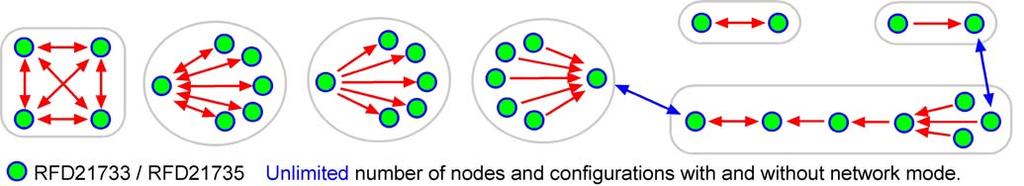
2 / Features WiFi interference tolerant. Bluetooth interference tolerant. Zigbee interference tolerant. Very low cost. No external parts required. No RF layout required. Easy and ready-to-use, hand-held, eval and application boards available. Ultra small 15mm x 15mm footprint. Fully contained, truly a finished, ready to use module. FCC, CE, IC (ETSI) Compliance approvals (pending). Typical range outdoor; 300 feet (100 meters), indoor 100 feet (33 meters). Worldwide 2.4GHz ISM band operation. User configurable without need for any programming. 2uA Ultra low power modes. Only 14mA current consumption at 0dbm RF power output. Only 17mA current consumption at -94 dbm receive sensitivity. 16 bit CRC data accuracy verification built-in. 32 bit unique factory ESN in every module (4 billion combination security). Flexible network modes, including broadcast and individual addressing. Optional version available for use with external antenna (). Switch on/off, logic, remote-control without the need for an external controller. Switch nodes individually addressable without the need for an external controller. Wide supply range +1.9V to +3.6V. Built-in, high performance internal antenna (). Peer to Peer (Ad-Hoc) networks and configurations. Point to Multi-Point networks and configurations. Multi-Point to Multi-Point networks and configurations. Selective addressing of any module by using factory built-in ESN. Fast-turn-around, minimal latency (20 millisecond). Patent pending interference tolerant protocol. Full application protocol runs transparent to the user. Easy to use, simple to design in. Stores up to 60 ESNs (Electronic Serial Numbers) for network modes. Many to one data modes ideal for multi-point data acquisition. Unlimited number of module nodes can communicate to each other. Custom Modules RF Digital's application firmware loaded into the / modules can be customized to fit application specific user requirements. RF Digital can design and manufacture fully custom modules to fit specific customer requirements. If you do not find what you're looking for, feel free to contact RF Digital with your requirements. Eval Kits See below for READY-TO-USE Eval boards. Application Protocol Mode Selector Chart 2
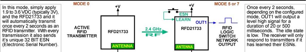
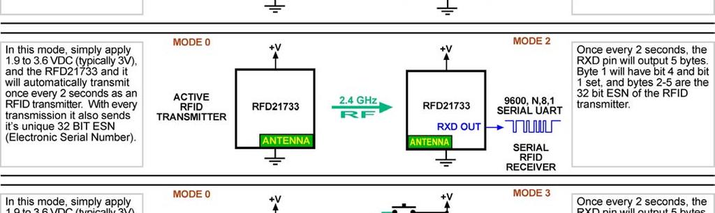
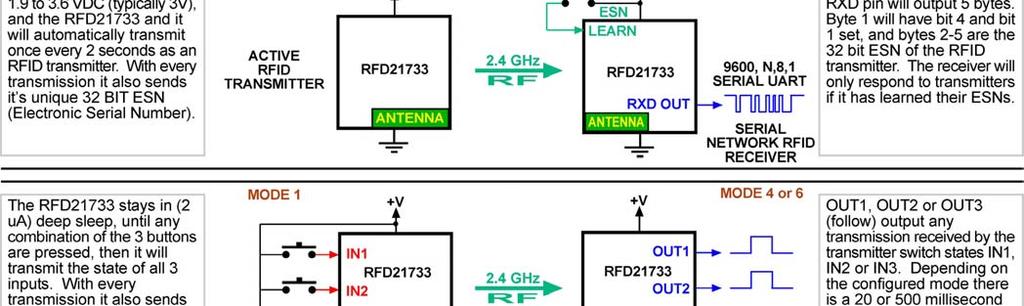
3 / System Configuration Examples / Application Configuration Examples 3
4 / Application Configuration Examples 4
5 / Application Configuration Examples 5


6 Differences Between Eval Boards The with built-in chip antenna is soldered onto the eval board. The antenna is self contained within the module. This eval board is self-contained and does not require an external antenna. The is soldered onto the eval board. There is a 1.2 inch wire antenna soldered onto the which connects to the external antenna pin through RF strip-line within the PCB layers. This eval board is self-contained and does not require an external antenna. The is soldered onto the eval board. There is a FEMALE SMA connector soldered onto the which allows the user to connect to an external 2.4 GHz antenna of their choice. The external antenna pin is routed to the SMA connector through strip-line within the PCB layers. This eval board requires a user supplied 2.4 GHz antenna with a MALE SMA connector. ANTENNA NOT INCLUDED 6


 mating socket.")
7 Eval Board Top and Bottom Labeled Views All three eval boards can be powered from their on-board CR2032 3V battery or through the 12 pin inch (2.54mm) pitch header, which can plug into directly into standard solderless breadboards or connect to mating a inch (2.54mm) mating socket. The Eval Boards can work as stand-alone or can be wired to your application. 7
 position, there is a low (0) on the input.")

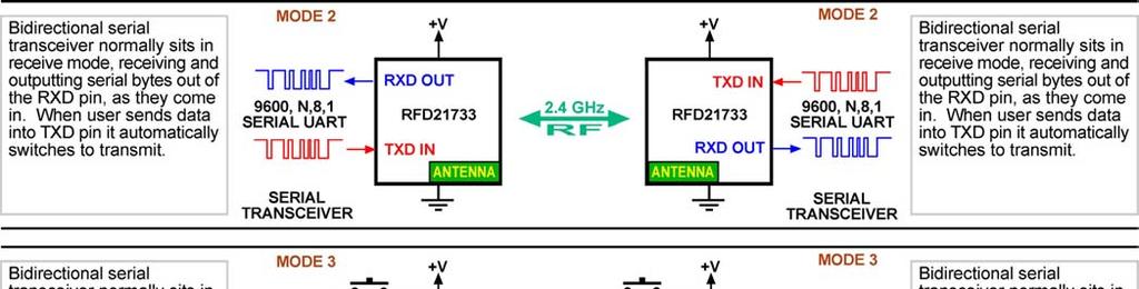
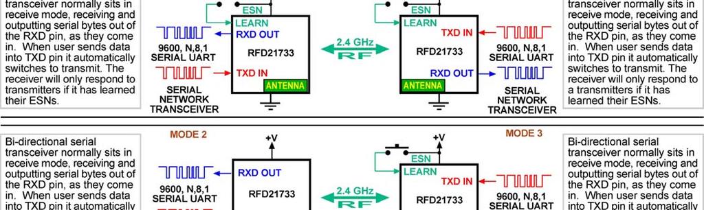
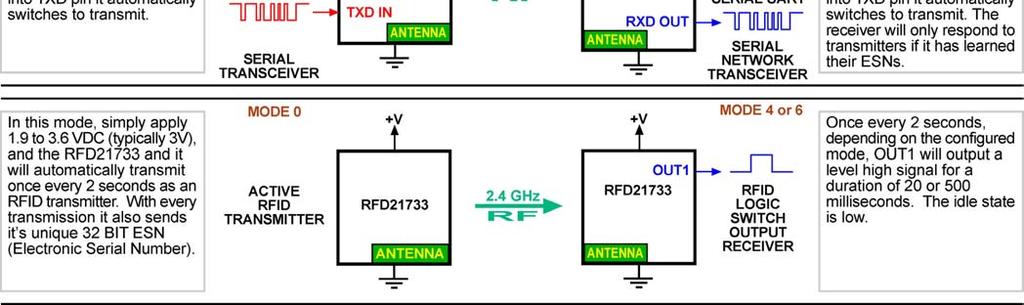
8 Mode Selector Switch The 8 different modes of the Application Protocol are selected using the 3-position dip-switch S5 shown in the examples below. The 3 inputs have resistor pull-downs to ground, so when the switch is in its OFF (open) position, there is a low (0) on the input. When the switch is in its ON (closed) position, it connects the input to +V, which produces a high (1). The proper way to read binary is MSB on the left and LSB on the right. Switch manufacturers label the switches from left to right and furthermore they commonly start with 1 rather then 0. So careful attention needs to be given to identify the switch positions. The binary is read from MSB to LSB, rather then LSB to MSB as shown in the examples below. To remove all doubt, only follow the examples shown below. Mode 0 Active RFID Transmitter Mode 1 3-Input Switch Logic Transmitter Mode 2 Serial UART Transceiver N1 Mode 3 Serial UART Transceiver N1 Network ON ON ON ON OFF OFF OFF OFF OFF OFF OFF OFF Mode 4 3-Output Switch Logic Receiver 500ms Hang Time Mode 5 3-Output Switch Logic Receiver 500ms Hang Time Network Mode 6 3-Output Switch Logic Receiver 20ms Hang Time Mode 7 3-Output Switch Logic Receiver 20ms Hang Time Network ON ON ON ON ON ON ON ON OFF OFF OFF OFF 8


9 Eval Board Top and Bottom View Pinout Eval Board Power Supply and Logic Levels - Important There is an internal 3.3 Volt (LDO) on the eval boards. At the (pin 2) +V input pin, you can supply 2.1VDC minimum and a maximum of 3.6VDC. When your supplied voltage is between 3.4V and 3.6V the internal regulator is in regulation and the internal supply to all parts will be 3.3V, and all signals on pins 9-12 will be at 3.3V logic. When 2.1V to 3.4V is supplied the internal 3.3V regulator is of regulation and tracks the input voltage (minus 100mv overhead). If you supply 2.5V your logic will be at 2.4V, and if you supply 2.1V your logic will be at 2.0V. The internal 3.3V regulator accept up to a 5V supply input, but at 5V supply, your logic levels on pins 9-12 will be at 3.3V, so use caution. So you will need to use 3.3V to 5V logic level shifters to run properly at 5V or you will cause damage to the module. When using a 5V supply, a very quick 5V level shifter method (not to be used for production) just for testing, which works in some cases would be to use a 22K resistor in series between the eval boards 3.3V logic and your 5V logic. There is a 47k pull down resistor internal to the board on pin 9-12 and this is just enough to switch the logic levels in both directions for a quick and dirty level shifter. 9
10 Firmware RF Digital offers firmware for the and modules meets many common user requirements. The firmware and a unique identifier are pre-programmed and tested at the factory. The programmed module is therefore immediately ready for use upon delivery. The firmware use the 3 mode select inputs to select the operating mode. These inputs are sampled when the module powers-on. Some of the operating modes have additional options which are described in the section for that mode. The firmware cannot be modified by the user. For applications that require alternative functionality, contact RF Digital for information about custom firmware to fit your specific requirements. Interference Immunity Algorithm The firmware employs RF Digital's Proprietary, Patent Interference Immunity Algorithm, which successfully functions in a WiFi environment without performance degradation. In addition, RF Digital's protocol provides a robust communication link in high RF noise environments. Electronic Serial Number Every RF Digital Module has its own 32-bit unique identifier (over 4 billion unique values), known as the Electronic Serial Number, or ESN. This value is assigned at the factory and cannot be changed by the user. The ESN is included in every packet that is transmitted, as part of the protocol overhead and is transparent to the user. The user does not ordinarily need to know what the ESN is. However, in certain cases it is helpful to know the serial number, and so a mechanism has been provided to read out the ESN. This method is documented in the UART section below. Network Mode The UART and the Receiver with logic output can be configured to accept data only from transmitters with which it has been associated, i.e. in its network. When in network mode, a module must learn the ESN of any module which it wishes to hear." The LEARN signal (listed in the UART and receiver sections below) is usually an input, pulled to GND through an external resistor. When LEARN is driven high for at least 20ms and then allowed to return to GND, the module enters learning mode. While in learning mode, the LEARN signal is changed to an output and driven high. During this time, the module will learn the ESN of the first module that sends any data; the data will be discarded, the ESN of the transmitting module will be learned by the receiving module. The receiving module indicates that it has learned the ESN by toggling the LEARN output on and off quickly three times. 10
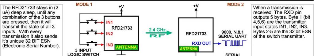
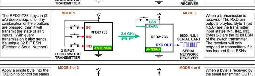
11 After learning the transmitting modules ESN, or after 10 seconds pass, the module will exit learning mode by driving LEARN low and then changing it back to an input. The LEARN / STATUS pin is bidirectional, it is an input when in the LEARN state and an output when in the STATUS state, so you must drive it using a series resistor, we recommend you not use any value smaller 1k ohm to limit the amount of load current. There is an internal 47k pull down resistor, so if you use a value of 1k series resistor that will easily be enough to drive it high against the internal 47k pull down resistor. Modules can learn up to 60 unique ESN s. ESN s cannot be deleted individually. The list of learned ESN s can be completely cleared by holding the LEARN signal high for at least 10 seconds and then releasing it. The module will erase its ESN list, and then drive the LEARN signal in a fast alternating high/low pattern for a few seconds to indicate that the ESN list is now empty. Once a module has learned the ESN of another module, it will accept any and all data from that module only and not any other modules. Up to 60 unique transmitters can be taught to one receiver. If a module is configured to any of the 3 Network modes and it has not learned any transmitters ESN, then it will not receive and output any data, until it learns at least one transmitter. This network feature can be used for peer-to-peer networks, point to multi-point networks, multi-point to multipoint networks. The association can be between two units for simple functions like opening a garage door or with many units to form complex networks with multiple nodes. Modes Mode 0 Active RFID Transmitter Pin # Pin Label Direction Function 13 +V Input +V Power 10 GND Input Ground 16 Mode Select 0 Input Tie to GND 17 Mode Select 1 Input Tie to GND 3 Mode Select 2 Input Tie to GND 4 TX LED Output Toggles high during transmission (1 blink every 2 seconds) 5 IN1 Input Active high switch input #1 (optional) if not used, pull to GND. 6 IN2 Input Active high switch input #2 (optional) if not used, pull to GND. 7 IN3 Input Active high switch input #3 (optional) if not used, pull to GND. The Active RFID Transmitter transmits a packet with its ESN every 2 seconds when the three inputs are all at a low logic level. If any of the three inputs go high, the module transmits the state of all three inputs every 15 ms, until all three inputs are low. The logic inputs should be tied low if they are not used in the end application. The module is active during transmit for 15ms, but remains in an ultra-low power mode for the rest of the 2 second interval. The average power over time is measured in microamps, such that a CR2032 battery should provide about 60 days of continuous use. If longer periods of use are required, a larger battery can be used to allow it to run up to years of time without replacing the battery, or contact RF Digital to inquire about a custom time setting which will reduce the transmission interval thus reducing the average power consumption. 11
12 Mode 1 Input Logic Transmitter Pin # Pin Label Direction Function 13 +V Input +V Power 10 GND Input Ground 16 Mode Select 0 Input Tie to +V 17 Mode Select 1 Input Tie to GND 3 Mode Select 2 Input Tie to GND 4 TX LED Output Toggles high during transmission (1 blink every 15 milliseconds) 5 IN1 Input Active high switch input #1 (optional) if not used, pull to GND. 6 IN2 Input Active high switch input #2 (optional) if not used, pull to GND. 7 IN3 Input Active high switch input #3 (optional) if not used, pull to GND. When all three switch inputs are low, the module does not transmit, but remains in an ultra-low-power state consuming only 2uA. When any of the three switch inputs go high, the module transmits the state of all three inputs. As long as any of the three inputs remain high, the module continues to transmit the state of all three inputs every 15ms, while transmitting it will draw about 14mA. Modes baud UART Pin # Pin Label Direction Function 13 +V Input +V Power 10 GND Input Ground 16 Mode Select 0 Input Tie to GND 17 Mode Select 1 Input Tie to +V 3 Mode Select 2 Input Tie to GND 4 Not Used Output Do not connect, not used. 5 Logic IO I/O Bidirectional switch logic I/O, if not used, pull to GND. 6 RXD Output RX Data Out, UART output of received data. 7 TXD Input TX Data In, UART input of data to transmit. Modes baud UART (Network) Pin # Pin Label Direction Function 13 +V Input +V Power 10 GND Input Ground 16 Mode Select 0 Input Tie to +V 17 Mode Select 1 Input Tie to +V 3 Mode Select 2 Input Tie to GND 4 Learn / Status I/O Pulse high to enter learn mode and LED Learn Status Output. 5 Logic IO I/O Bidirectional switch logic I/O, if not used, pull to GND. 6 RXD Output RX Data Out, UART output of received data. 7 TXD Input TX Data In, UART input of data to transmit. 12
13 9600 baud half-duplex UART, suitable for connection to a microcontroller, or a level translator (such as a MAX202) to an RS-232 port. RF transmission takes priority over RF reception, so that a module will not receive anything over the air if it is given a full-speed stream of serial data on TX_in. The UART is configured for 9600 baud, 8 data bits, 1 stop bit, and no parity. Because the module does not perform any parity checking on the data stream, it is possible to use 7 data bits with even or odd parity instead of 8 data bits with no parity. When in UART mode, the module remains in an active state with the radio enabled in receive mode. If you are only using the module as a receiver, you must terminate the TXD line with a pull up resistor to +V so you do not leave a floating input which may cause unintentional transmissions by the module detecting anything other then a solid logic level on the TXD pin. The same applies for the general purpose Logic I/O (pin 5). End-to-End Latency In order to use the radio efficiently, the firmware buffers data received from the UART into packets which are transmitted over the radio. The firmware transmits a packet when it has buffered 12 bytes of data, or 15ms after receiving a byte of data. On the receiving end, data will be transmitted over the UART at line speed, with no pauses between the bytes (other than the RS-232 start and stop bits). The buffering allows for the to support a full 9600 baud data rate. The buffering and latency may cause problems with certain microcontrollers that can not tolerate serial data into their UART in a constant stream at N1. One possible solution is to add a 16ms delay on the transmitting side which will cause each byte to be sent in its own packet by the module and therefore on the receiving end the bytes will be outputted at a pace of one byte every 16ms which will help your controller of choice handle the fast UART data. As an example, consider a scenario where one system is sending a byte of data every 8ms. When module 1 receives the 1 st byte on its UART, the 15ms timer begins. The 2 nd byte arrives before 15ms elapses, and so the first two bytes are sent in a single packet over the air to Module 2. Module 2 will transmit the bytes on its UART with no delay between them. Module 1 receives the third byte on its UART, and re-starts the 15ms timer. As with the 2 nd byte, the 4 th byte arrives before 15ms elapses, and so the 3 rd and 4 th bytes are also sent in a single packet over the air, as illustrated in the following timing diagram. Bi-Directional IO Signal Operation UART mode includes an additional bi-directional general-purpose IO line. The IO signal is generally an input, and should be pulled to GND with an appropriately sized resistor (for example 10k). If the IO signal is driven high, the 13
14 module will transmit this information, and any UART which receives the data will turn its IO signal into an output and drive it high. This will continue until 20ms pass without receiving any new data, or until the module receives a packet which indicates that the IO signal should be driven low and turned back to an input. The state of the IO signal does not require any extra data in the radio stream, and so is free in the packet overhead. When the module is driving its IO signal high, it will periodically change the pin to an input and check to see if it remains high, before changing it back to an output. This causes a periodic dip in the signal, 1ms every 12-16ms, and so any circuitry which relies on a steady-state output from the IO signal should include conditioning (for example a retriggerable one-shot with a hold time of 2ms) to avoid adverse effects. ESN Read-back In certain applications, it is helpful to know the ESN of a module. There is a provision in both UART modes to read back the ESN when the module comes out of reset. ESN read-back is not available in any of the other modes. Pin 14 on the / is marked as Do Not Connect, this pin normally is not connected for all applications except for reading back the ESN. So that is why it is mentioned here and not anywhere else. The reset signal does not have to be used, instead of using reset you can use power the module off and then back on. The reset is a cleaner way of doing it. If you are using the,, eval boards, the reset signal is available on pin 5 of the 12 pin connector. Internal to the / there is a 3.3K pull up resistor on the reset signal, so when you are not using it, you can just leave it open. To activate ESN read-back: 1. Place the module in a reset state by holding the /RESET signal low. 2. Hold the LEARN signal high. 3. Release the /RESET signal. 4. Wait 250ms. If the LEARN signal goes low at any time during this 250ms interval, the module immediately exits ESN read-back mode. 5. Release the LEARN signal. 6. Send the string READ ESN (all capitals, one space between the two words) at N1 into the module on the TXD Input signal. If this string is not received within 1 second, the module exits ESN readback mode. The module will respond with the ESN and a firmware identifier on the RXD Output signal at N1, and then exit ESN read-back mode. An example of the output is: 314CE686: v1.2 11/18/08 08:45:16$ The ESN is 8 characters, representing a 32-bit number in hexadecimal format. A colon separates the ESN from the Firmware ID. The Firmware ID is 32 bytes long. The output is terminated with a carriage return/line feed pair. When the module exits ESN read-back mode, or if the LEARN signal is not high when the module exists reset, the module will enter regular operation in Mode 2 or 3, according to the mode select signals. 14
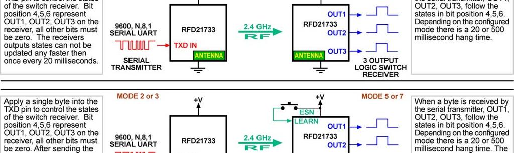
15 Modes 4 Receiver with Logic Output (500ms hang-time) Pin # Pin Label Direction Function 13 +V Input +V Power 10 GND Input Ground 16 Mode Select 0 Input Tie to GND 17 Mode Select 1 Input Tie to GND 3 Mode Select 2 Input Tie to +V 4 Not Used Output Leave open, not used. 5 OUT1 Output Active high switch output #1, 500 millisecond hang-time. 6 OUT2 Output Active high switch output #2, 500 millisecond hang-time. 7 OUT3 Output Active high switch output #3, 500 millisecond hang-time. Modes 5 Receiver with Logic Output (Network) (500ms hang-time) Pin # Pin Label Direction Function 13 +V Input +V Power 10 GND Input Ground 16 Mode Select 0 Input Tie to +V 17 Mode Select 1 Input Tie to GND 3 Mode Select 2 Input Tie to +V 4 Learn / Status I/O Pulse high to enter learn mode and LED Learn Status Output. 5 OUT1 Output Active high switch output #1, 500 millisecond hang-time. 6 OUT2 Output Active high switch output #2, 500 millisecond hang-time. 7 OUT3 Output Active high switch output #3, 500 millisecond hang-time. Modes 6 Receiver with Logic Output (20ms hang-time) Pin # Pin Label Direction Function 13 +V Input +V Power 10 GND Input Ground 16 Mode Select 0 Input Tie to GND 17 Mode Select 1 Input Tie to +V 3 Mode Select 2 Input Tie to +V 4 Not Used Output Leave open, not used. 5 OUT1 Output Active high switch output #1, 20 millisecond hang-time. 15
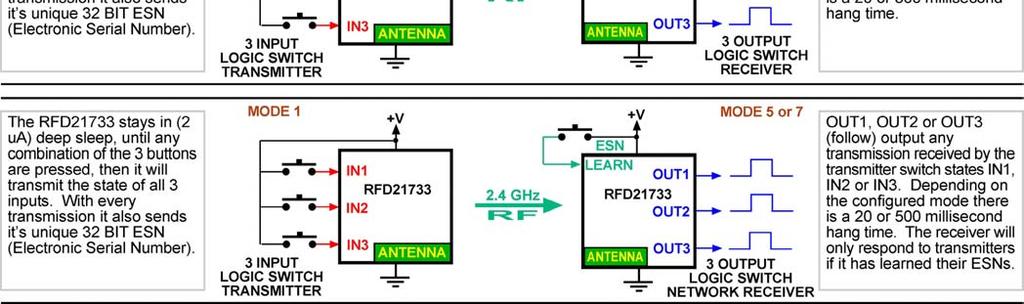
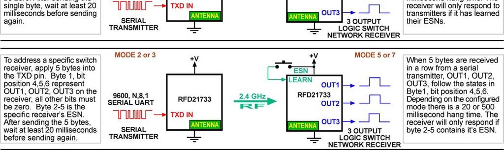
16 6 OUT2 Output Active high switch output #2, 20 millisecond hang-time. 7 OUT3 Output Active high switch output #3, 20 millisecond hang-time. Modes 7 Receiver with Logic Output (Network) (20ms hang-time) Pin # Pin Label Direction Function 13 +V Input +V Power 10 GND Input Ground 16 Mode Select 0 Input Tie to +V 17 Mode Select 1 Input Tie to +V 3 Mode Select 2 Input Tie to +V 4 Learn / Status I/O Pulse high to enter learn mode and LED Learn Status Output. 5 OUT1 Output Active high switch output #1, 20 millisecond hang-time. 6 OUT2 Output Active high switch output #2, 20 millisecond hang-time. 7 OUT3 Output Active high switch output #3, 20 millisecond hang-time. In modes 4 through 7, the module is always in receiving mode. The receiver drives its outputs to match the values received in a packet from a transmitter. This allows up to 8 possible (2 3 ) combinations on the receiver s outputs. Since a transmitter does not send any data when all of its inputs are low, there must be a mechanism for turning off the receiver s outputs in the absence of data. When Mode Select 1 is pulled to GND, the receiver will maintain its output state for 500ms or until it receives new data, whichever comes first. The 500ms is referred to as the hang time, or the time that the outputs will hang in the absence of new data. If Mode Select 1 is pulled to +V, the hang time is 20ms. Hang time is a trade-off between latency and resiliency to packet loss. With all RF systems sometimes a packet will be lost, especially as the distance between the transmitter and the receiver grows. If an output is connected to a relay driver, packet loss will result in chattering on the relay, which will not have good results. The 500ms hang time is perfect for applications like a keyless entry system or a garage door opener. For faster switching to the all off state, the 20ms hang time is preferred. Since a transmitter sends new data every 15ms, the time delay to turn off all outputs is only 5ms more than to update the outputs to a different state where at least one of them is still driven high. 16
17 The following timing diagrams show the operation of a logic transmitter and a logic receiver with the different hang time options. In the first diagram, the logic transmitter s inputs are all asserted, and then sequentially de-asserted. There is a small delay between the transmitter input going high and the corresponding output on the receiver going high, due to the time required to transmit over the air. Note that when the last input on the transmitter is de-asserted, there is a 500ms delay before the receiver deasserts its last output. The second diagram shows the same operation at the transmitter, but with the receiver configured with a 20ms hang time. Note that shortly after the last input is de-asserted, the receiver updates its output state to turn off all outputs. Communication between UART and Switch Logic Receiver/Transmitter The Logic Receiver and Transmitter modes are able to communicate with a module operating in one of the UART modes, which opens up a wide range of possible applications involving PC s or embedded systems with serial communications capability. Logic Transmitter to UART A Logic Transmitter (whether RFID or not) sends the state of its inputs as a single byte of data, followed by its ESN as four bytes. A UART can receive this packet and output it as a binary stream to a PC serial port or an embedded microcontroller. The format of the data is: 17
18 Byte Bit 7 Bit 6 Bit 5 Bit 4 Bit 3 Bit 2 Bit 1 Bit 0 1 Input 3 Input 2 Input 1/ RFID RFID 2 ESN Byte 1 3 ESN Byte 2 4 ESN Byte 3 5 ESN Byte 4 In the first byte, bits 6 through 4 carry the state of the logic inputs, with a 1 indicating the logic input on the transmitter is high, and a 0 indicating it is low. An RFID Transmitter will set both bits 0 and 4 to indicate that it is a periodic transmission from an RFID Transmitter, and is set to 1 if this is the case. For example, if an RFID Transmitter with ESN 314CE686 sent a packet on its 2-second interval, a UART would receive the bytes C E6 86 in binary format. If input #1 on that same RFID transmitter were pulled high, the UART would receive the bytes C E6 86 in binary format; since bit 0 is clear, the receiver can tell that this was not a periodic transmission. Most ESN s will contain at least one unprintable character, and so this data will not be suitable for displaying directly in a terminal package (such as HyperTerminal), but a PC-based program or an embedded system (such as the BASIC Stamp) can collect the data and display it in a more friendly fashion. The ESN which the UART receives is the same one that is in the packet header. If the UART is in Network Mode, and has not learned the ESN, it will never receive the packet, and there will be no output on the serial port. UART to Logic Receiver A UART can also send data to a logic receiver, which will decode the data and assert its outputs as though it received a packet from a logic transmitter. The data format is very similar to the one described in the previous section. The differences matter only when the receiver is in Network Mode. The UART must follow a packet with at least 15ms of no data so that all bytes as described below are sent as a single packet. Note that a UART can send a single zero byte all bits clear to force a receiver to turn off its outputs immediately, regardless of hang time. Format 1: Byte Bit 7 Bit 6 Bit 5 Bit 4 Bit 3 Bit 2 Bit 1 Bit 0 1 Output 3 Output 2 Output 1 When the receiver is not in Network Mode, the receiver will accept any packet it receives, and so this is the preferred format. A receiver in Network Mode will use the UART s ESN from the packet header to determine if it should accept the packet. This allows one UART to send the same data to multiple receivers, provided that each receiver has learned the UART s ESN. 18
19 Format 2: Byte Bit 7 Bit 6 Bit 5 Bit 4 Bit 3 Bit 2 Bit 1 Bit 0 1 Output 3 Output 2 Output 1 2 ESN Byte 1 3 ESN Byte 2 4 ESN Byte 3 5 ESN Byte 4 To allow individual addressing of receivers in Network Mode, the UART can send a particular receiver s ESN after the byte for the logic state. In this case, the receiver will only accept the packet if the ESN in the data portion matches the receiver s own ESN. If the receiver is actively learning ESN s, it will learn only the ESN from the packet header; the ESN in the data portion will not be learned. Electrical Characteristics Operating Conditions Symbol Parameter Minimum Typical Maximum VDD Supply voltage 1.9V 3.0V 3.6V Operating Temperature -40 C +85 C Power Consumption Conditions: VDD = 3.0V, T A = +25 C Logic Transmitter or Active RFID Transmitter Parameter Minimum Typical Maximum Ultra-low power mode - Switch Logic Transmitter / RFID 2uA UART or Switch Logic Transmitter / Receiver Parameter Minimum Typical Maximum Listening - Receiving 17mA Transmitting 14mA 19
20 Overall Dimensions Top View Overall Dimensions Side View 20

21 PCB Layout 21
22 FCC NOTICE Relating to Model Number R24 (RFD Stock Code: ) The unit should have a permanently attached label in a conspicuous location with the following statement: FCC ID: UYI24 This device complies with Part 15 of the FCC Rules. Operation is subject to the following two conditions: (1) This device may not cause harmful interference and (2) this device must accept any interference received, including interference that may cause undesired operation. NOTES: 1. The FCC does not specify the size of the label or the lettering thereon. The only requirement is that the text be legible. 2. If the entire label can not be placed on the unit due to space constraint, only FCC ID may be displayed on the unit. In such cases, the compliance statement will have to be included in the "user s manual". NOTE: Device must be smaller than a man s palm. ** If the unit also interfaces with phone line, it requires additional information on the label - refer to part 68 information ** 22
23 SAMPLE FCC STATEMENT TO BE INCLUDED IN USER'S MANUAL INSTRUCTION TO THE USER (if device DOES NOT contain a digital device) The user is cautioned that changes or modifications not expressly approved by the party responsible for compliance could void the user s authority to operate this equipment. INSTRUCTION TO THE USER (if device contains a digital device) This equipment has been tested and found to comply with the limits for a class B digital device, pursuant to part 15 of the FCC Rules. These limits are designed to provide reasonable protection against harmful interference in a residential installation. This equipment generates, uses and can radiate radio frequency energy and if not installed and used in accordance with the instructions, may cause harmful interference to radio communications. However, there is no guarantee that interference will not occur in a particular installation. If this equipment does cause harmful interference to radio or television reception, which can be determined by turning the equipment off and on, the user is encouraged to try to correct the interference by one or more of the following measures: * Reorient or relocate the receiving antenna. * Increase the separation between the equipment and receiver. * Connect the equipment into an outlet on a circuit different from that to which the receiver is connected. * Consult the dealer or an experienced radio/tv technician for help. In order to maintain compliance with FCC regulations, shielded cables must be used with this equipment. Operation with non-approved equipment or unshielded cables is likely to result in interference to radio and TV reception. The user is cautioned that changes and modifications made to the equipment without the approval of manufacturer could void the user's authority to operate this equipment. 23
24 Important Notice RF Digital reserves the right to make corrections, modifications, and/or improvements to the product and/or its specifications at any time without notice. RF Digital assumes no liability for the user s product and/or applications. RF Digital products are not authorized for use in safety-critical applications, including but not limited to life-support applications. RF Digital assumes no liability for parts or their application beyond replacement or refunding the original purchase price. All trademarks and trade names belong to their respective owners. End of Document. 24
900 MHz. Frequency Hopping RS-485 Master/Slave auto-sensing radio interface.
 MDR210A-485 900 MHz. Frequency Hopping RS-485 Master/Slave auto-sensing radio interface. Black Box Corporation Lawrence, PA - http://www.blackbox.com - Ph 877-877-BBOX - Fax 724-746-0746 Table of Contents
SMARTALPHA RF TRANSCEIVER
 SMARTALPHA RF TRANSCEIVER Intelligent RF Modem Module RF Data Rates to 19200bps Up to 300 metres Range Programmable to 433, 868, or 915MHz Selectable Narrowband RF Channels Crystal Controlled RF Design
Datasheet LT1110 Wireless Module. Version 3.1
 A Version 3.1 REVISION HISTORY Version Date Notes Approver 3.0 13 Jan 2014 Separated into two separate docs: Hardware Integration Guide and User Guide. Marked as Rev 3.0 to match User Guide. Sue White
Blue Point Engineering
 Overview Blue Point Instruction Board 2-CH Boards, Terminal Block and Ribbon Cable I Type: RF Radio (315 MHz) 1-2 Channels (FCC Part 15 Compliant Components). Operating Voltage: 6-15 VDC @ 1 Amp (Wall
RQT-xxx-RCVR Owner s Manual Quick Talk TM Wireless Voice Monitor & Alarm transmitter with factory installed MHz Keyfob Receiver
 RQT-xxx-RCVR Owner s Manual Quick Talk TM Wireless Voice Monitor & Alarm transmitter with factory installed 433.92 MHz Keyfob Receiver RQT-151-RCVR RQT-151M-RCVR RQT-451-RCVR RQT-152-RCVR RQT-152M-RCVR
PCK43302, PCK MHz Penta series Keyring Remotes with Frequency Hopping
 PCK43302, PCK43304 433MHz Penta series Keyring Remotes with Frequency Hopping FEATURES Small Size keyring remote with 2 or 4 buttons Dual Coding System, dip switch and encrypted code Transmission on 5
Applications. Operating Modes. Description. Part Number Description Package. Many to one. One to one Broadcast One to many
 RXQ2 - XXX GFSK MULTICHANNEL RADIO TRANSCEIVER Intelligent modem Transceiver Data Rates to 100 kbps Selectable Narrowband Channels Crystal controlled design Supply Voltage 3.3V Serial Data Interface with
RF RECEIVER DECODER RDF1. Features Complete FM Receiver and Decoder. Applications
 Features Complete FM Receiver and Decoder. Small Form Factor Range up to 200 Metres* Easy Learn Transmitter Feature. Learns 40 transmitter Switches 4 Digital and 1 Serial Data outputs Outputs, Momentary
OEM KEYFOB TRANSMITTER DATA GUIDE
 CMD-KEYX-XXX OEM KEYFOB TRANSMITTER DATA GUIDE DESCRIPTION The Linx CMD-KEYX-XXX Remote Command keyfob is ideal for generalpurpose remote control and command applications. The unit has been precertified
RM24100D. Introduction. Features. 2.4GHz 100mW RS232 / RS485 / RS422 DSSS Radio Modem (IEEE compliant) Operating Manual English 1.
 Operating Manual English 1.") RM24100D 2.4GHz 100mW RS232 / RS485 / RS422 DSSS Radio Modem (IEEE 802.15.4 compliant) Operating Manual English 1.09 Introduction The RM24100D radio modem acts as a wireless serial cable replacement and
RM24100D 2.4GHz 100mW RS232 / RS485 / RS422 DSSS Radio Modem (IEEE 802.15.4 compliant) Operating Manual English 1.09 Introduction The RM24100D radio modem acts as a wireless serial cable replacement and
Revision WI.232FHSS-25-FCC-R and RK-WI.232FHSS-25-FCC-R USER S MANUAL
 Revision 1.0.3 WI.232FHSS-25-FCC-R and RK-WI.232FHSS-25-FCC-R USER S MANUAL RADIOTRONIX, INC. WI.232FHSS-25-FCC-R/ RK-WI.232FHSS-25-FCC-R USER S MANUAL Radiotronix 905 Messenger Lane Moore, Oklahoma 73160
User Manual WHM520V. 1. Introduction. 2. Feature
 User Manual 1 Introduction The module is wireless audio module based on AV5100 The AV5100 is 5GHz wireless audio SoC (System-on-chip), optimized for building point to multi-point digital wireless audio
AT-XTR-7020A-4. Multi-Channel Micro Embedded Transceiver Module. Features. Typical Applications
 AT-XTR-7020A-4 Multi-Channel Micro Embedded Transceiver Module The AT-XTR-7020A-4 radio data transceiver represents a simple and economical solution to wireless data communications. The employment of an
swarm bee LE Development Kit User Guide
 Application Note Utilizing swarm bee radios for low power tag designsr Version Number: 1.0 Author: Jingjing Ding swarm bee LE Development Kit User Guide 1.0 NA-14-0267-0009-1.0 Document Information Document
GC9838-LR - INTELLIGENT HYBRID PLC-RF DIN RAIL MODEM
 GC9838-LR - INTELLIGENT HYBRID PLC-RF DIN RAIL MODEM and a built-in sub-ghz wireless module to allow adaptive networking over different media. The wireless connectivity can be available in LoRa for tree-structure
RM24100A. *Maximum transmit power output levels and local radio frequency regulator bodies must be obeyed in the country of operation.
 RM24100A 2.4GHz 100mW RS232 / RS485 / RS422 DSSS Radio Modem (IEEE 802.15.4 compliant) Operating Manual English 1.02 Introduction The RM24100A radio modem acts as a wireless serial cable replacement and
Meshreen MS5168 ZigBee Module MS5168-Mxx series USER MANUAL FCC ID :2AC2E-68M04
 Meshreen MS5168 ZigBee Module MS5168-Mxx series USER MANUAL FCC ID :2AC2E-68M04 Meshreen DS MS5168 / info@meshreen.com 1 Content 1. Introduction... 3 1.1 Variants... 3 2. Specification... 4 2.1 Pin configurations...
Blue Point Engineering Inc.
 Engineering Inc. ireless Radio Control of Puppets Setup Overview RF Control C Pointing the ay to Solutions! Hardware Setup Overview Page 1 Servo No.1 Servo No.2 Control Signal Line RX8ch1,2 Servo Board
swarm radio Platform & Interface Description
 Test Specification Test Procedure for Nanotron Sensor Modules Version Number: 2.10 Author: Thomas Reschke swarm radio Platform & Interface Description 1.0 NA-13-0267-0002-1.0 Document Information Document
Datasheet. Bluetooth Smart Module. Pacwave Bluetooth Smart (BLE) Module DESCRIPTION FEATURES
 Module DESCRIPTION FEATURES") Pacwave Bluetooth Smart (BLE) Module FEATURES Built in CSR μenergy CSR1010 Bluetooth Smart (v4.1) chipset +7.5dBm Maximum RF Transmit Output Power 92.5dBm RF Receive Sensitivity RSSI Monitoring Built in
Pacwave Bluetooth Smart (BLE) Module FEATURES Built in CSR μenergy CSR1010 Bluetooth Smart (v4.1) chipset +7.5dBm Maximum RF Transmit Output Power 92.5dBm RF Receive Sensitivity RSSI Monitoring Built in
Embedded Radio Data Transceiver SV611
 Embedded Radio Data Transceiver SV611 Description SV611 is highly integrated, multi-ports radio data transceiver module. It adopts high performance Silicon Lab Si4432 RF chip. Si4432 has low reception
CCR24T CCR24R. User s Guide WIRELESS TRANSMITTER SYSTEM WARRANTY SERVICE CARD WARRANTY CARD
 WARRANTY SERVICE CARD WARRANTY CARD PRODUCT NAME Wireless Transceiver System PERIOD MODEL NAME CCR24GEN YEAR PURCHASE DATE.. 200_ From the date of WARRANTY PERIOD.. 200_ purchase. CUSTOMER S ADDRESS :
CDR-915 Data Radio Module INTEGRATOR S GUIDE
 CDR-915 Data Radio Module Coyote DataCom, Inc. 3941 Park Drive, Suite 20-266, El Dorado Hills, CA 95762 Tel. 916-933-9981 Fax 916-913-0951 www.coyotedatacom.com TABLE OF CONTENTS General Information and
U S E R S M A N U A L
 U S E R S M A N U A L C2104001 BCM 43224 WiFi Card Contents SECTION ONE: INTRODUCTION... 3 1. INTRODUCTION... 3 1.1 SCOPE... 3 1.2 FUNCTION... 3 1 2 PRODUCT SPECIFICATION... 4 2.1 HARDWARE SPECIFICATION...
Remote Switching. Remote Gates. Paging.
 Features Miniature RF Receiver and Decoder. Advanced Keeloq Decoding Advanced Laser Trimmed Ceramic Module AM Range up to 100 Metres FM Range up to 150 Metres Easy Learn Transmitter Feature. Outputs, Momentary
IMPORTANT: READ AND UNDERSTAND ALL INSTRUCTIONS BEFORE BEGINNING INSTALLATION
 INSTALLATI INSTRUCTIS Model: RB-G-K10 IMPORTANT: READ AND UNDERSTAND ALL INSTRUCTIS BEFORE BEGINNING INSTALLATI The Miller Edge RBand Monitored Gate Edge Transmitter/Receiver system is intended to provide
CRUX II/BTGPS USER GUIDE. Model:D1598
 CRUX II/BTGPS USER GUIDE Model:D1598 0 Federal Communication Commission Interference Statement This equipment has been tested and found to comply with the limits for a Class B digital device, pursuant
Remote Switching. Remote Gates. Paging.
 Features Miniature RF Receiver and Decoder. Advanced Keeloq Decoding AM Range up to 100 Metres FM Range up to 150 Metres Easy Learn Transmitter Feature. Outputs, Momentary or Latching & Serial Data. Direct
SRWF-1022 Series Low Power Wireless Transceiver Module User Manual
 SRWF-1022 Series Low Power Wireless Transceiver Module User Manual Page 1 of 6 I. SRWF-1022 SRWF-1022 User Manual (V1.1) SRWF-1022, the low-power wireless transceiver module is used as the wireless command
Model RTX-12 Radio Modem
 Model RTX-12 Radio Modem Grants Pass, Oregon 154 Hillview Drive Grants Pass, Oregon 97527 (541) 474-6700 Fax: (541) 474-6703 Both the RTX-12A and the RTX-12OEM are normally supplied with full transmit
INSTALLATION AND OPERATING MANUAL
 INSTALLATION AND OPERATING MANUAL FOR RBDA-PCS-1/25W-90-A INDOOR REPEATER TABLE OF CONTENTS PARAGRAPH PAGE NO BDA OVERVIEW 3 BDA BLOCK DIAGRAM DESCRIPTION 3 FCC INFORMATION FOR USER 3 BDA BLOCK DIAGRAM
Interface Manual Tank Level Float Stick System
 1 Interface Manual Tank Level Float Stick System SignalFire Model: Sentinel-FS-3BIS The SignalFire Sentinel Float Stick Node is an Intrinsically Safe device with the following features: - Standard SignalFire
Operating Distance An operating distance (in conjunction with our GLR27 series receivers) of 350 metres is possible.
 of 350 metres is possible.") ELSEMA 27MHz HAND HELD GIGALINK TRANSMITTERS GLT2700, GLT2701, GLT2702, GLT2703, GLT2704 and GLT2708 Features Over 4 billion code combinations Can program any number of transmitters to a receiver High
ELSEMA 27MHz HAND HELD GIGALINK TRANSMITTERS GLT2700, GLT2701, GLT2702, GLT2703, GLT2704 and GLT2708 Features Over 4 billion code combinations Can program any number of transmitters to a receiver High
IMPORTANT: THIS DEVICE MUST BE PROFESSIONALLY INSTALLED. READ AND UNDERSTAND ALL INSTRUCTIONS BEFORE BEGINNING INSTALLATION.
 INSTALLATI INSTRUCTIS Model: RB-G-K10 IMPORTANT: THIS DEVICE MUST BE PROFESSIALLY INSTALLED. READ AND UNDERSTAND ALL INSTRUCTIS BEFORE BEGINNING INSTALLATI. The Miller Edge RBand Monitored Gate Edge Transmitter/Receiver
Purchase the sample:http://www.aliexpress.com/store/ E32-TTL-100 Datasheet V Feature E32-TTL-100
 E32-TTL-100 Datasheet V1.0.1.Introduction E32-TTL-100 1.1 Feature E32-TTL-100 E32-TTL-100 is a wireless transceiver module with LoRa spread-spectrum technology, operates at 434MHz, based on original imported
DIGICELL ANYNET NETWORK ACCESS MODULE
 Comm Activity Network Status Service DigiCell Any NET Network Access Module Network Interface Network Service AMPS Cellemetry GSM SMS CDMA GPRS Ethernet 1xRTT RS-232 TCP/IP Input 1 Standard S3 off, S4
OEM HANDHELD TRANSMITTER DATA GUIDE
 CMD-HHTX-XXX OEM HANDHELD TRANSMITTER DATA GUIDE DESCRIPTION The Linx CMD-HHTX-XXX Remote Command Unit is ideal for generalp u rpose remote control and command applications. The unit has been pre-certified
OEM KEYFOB TRANSMITTER DATA GUIDE DESCRIPTION FEATURES
 DESCRIPTION WIRELESS MADE SIMPLE OEM KEYFOB TRANSMITTER DATA GUIDE The Linx CMD-KEY#-***-xxx Keyfob transmitter is ideal for general-purpose remote control and command applications. It has been pre-certified
Analog & Digital I/O Wireless Bridge USERS MANUAL R02
 Analog & Digital I/O Wireless Bridge USERS MANUAL R02 Contents Overview... 3 Specifications... 3 Absolute Maximum Ratings... 3 Recommended Operating Conditions... 3 Performance... 4 Power Requirements...
Catalog
 - 1 - Catalog 1. Description...- 3-2. Features...- 3-3. Application...- 3-4. Block Diagram...- 3-5. Electrical Characteristics... - 4-6. Operation... - 4-1) Power on Reset...- 4-2) Setting Mode... - 5-3)
SmartRadio Transmitter / Receiver
 Easy to use Radio Transmitter & Receivers AM Radio Hybrid Technology Supports Data or Telemetry communications Simple CMOS/TTL Data Interface Automatic data encryption / decryption Host Interface up to
Keycards come with an imbedded RFID chip and antenna, there is no battery in the keycards. The keycards are encrypted and only
 Index Keycards 02 The following is a description of the type of Keycards and function 03 Programming and Initialization of the RFID Lock 04 Procedure for Initialization 05 Programming- Adding Keycards
AN0509 swarm API Country Settings
 1.0 NA-15-0356-0002-1.0 Version:1.0 Author: MLA Document Information Document Title: Document Version: 1.0 Current Date: 2015-04-16 Print Date: 2015-04-16 Document ID: Document Author: Disclaimer NA-15-0356-0002-1.0
Round shape, white case with 3M adhesive sticker, including 2pcs ER12450 battery and industrial package, special for indoor location, RoHS
 Beacon / ibeacon / MiniBeacon FCC Statement This equipment has been tested and found to comply with the limits for a Class B digital device, pursuant to Part 15 of the FCC Rules. These limits are designed
RF (RADIO FREQUENCY) WIRELESS PENDANT
 WIRELESS PENDANT") NOTE: The following information is an addition to the Operation section in the lift system owner s manual. It describes the RF wireless pendant for your lift system. You must read the lift system owner
NOTE: The following information is an addition to the Operation section in the lift system owner s manual. It describes the RF wireless pendant for your lift system. You must read the lift system owner
PTT- Z or PTT-U PUSH-TO-TALK Specification
 Federal Communication Commission Interference Statement This equipment has been tested and found to comply with the limits for a Class B digital device, pursuant to Part 15 of the FCC Rules. These limits
Blue Point Engineering Inc.
 nc. Wireless Radio Control of Puppets Setup Overview RF Control C Hardware Setup Overview Servo No.1 Servo No.2 Control Signal Line RX8-ch1,2 Servo Board WZ-12 RX8-ch3,4 Servo Board WZ-12 Power Line DC
VDBTLE24. BTLE Single Mode Module with USB. Description. Applications
 BTLE Single Mode Module with USB VDBTLE24 Description VDBTLE24, Bluetooth low energy single mode module is a single mode Bluetooth 4.0 device targeted for low power sensors and accessories. VDBTLE24 offers
ALPHA Encoder / Decoder IC s
 EASY TO USE TELEMETRY SYSTEM USING ALPHA MODULES Features 3 digital I/O Serial Data output Connects directly to ALPHA Modules Easy Enc / Dec Pairing Function Receiver Acknowledge Signal Minimal External
HC-12 Wireless Serial Port Communication Module
 HC-12 Wireless Serial Port Communication Module User Manual version 2.3C (updated from v1.1 English and v2.3 Chinese) Product Applications Wireless sensor Community building security Robot wireless control
RN-41-SM. Class 1 Bluetooth Socket Module. Features. Applications. Description. Block Diagram. rn-41sm-ds 9/9/2009
 RN-41-SM www.rovingnetworks.com rn-41sm-ds 9/9/2009 Class 1 Bluetooth Socket Module Features Socket module 3/5V DC TTL I/O Fully qualified Bluetooth 2.1/2.0/1.2/1.1 module Bluetooth v2.0+edr support Low
APPLICATION BULLETIN. SERIAL BACKGROUNDER (Serial 101) AB23-1. ICS ICS ELECTRONICS division of Systems West Inc. INTRODUCTION CHAPTER 2 - DATA FORMAT
 AB23-1. ICS ICS ELECTRONICS division of Systems West Inc. INTRODUCTION CHAPTER 2 - DATA FORMAT") ICS ICS ELECTRONICS division of Systems West Inc. AB- APPLICATION BULLETIN SERIAL BACKGROUNDER (Serial 0) INTRODUCTION Serial data communication is the most common means of transmitting data from one point
ICS ICS ELECTRONICS division of Systems West Inc. AB- APPLICATION BULLETIN SERIAL BACKGROUNDER (Serial 0) INTRODUCTION Serial data communication is the most common means of transmitting data from one point
RF Engine Model RF100 Part Numbers: RF100PC6 and RF100PD6 Document Revision v1.0
 DATA SHEET RF Engine Model RF100 Part Numbers: RF100PC6 and RF100PD6 Document Revision v1.0 2011 Synapse, All Rights Reserved All Synapse products are patented or patent pending Specifications are subject
GX_W60_V3.5 WIFI Video module Mnaual
 GX_W60_V3.5 WIFI Video module Mnaual W60 Tel:86-755-26066032 Fax:26002892 Web site:www.netopsun.com 1 / 8 1 summary 1.1 overview of the whole W60_WIFI module is the latest introduction of crown Asahi Technology
9RCT4334 Four Button. 2 3/4 X 1 3/8 X 9/16 (70mm x 35mm x 14mm) 2 3/4 x 2 1/8 x 1 (70mm x 55mm x 25mm)
 2 3/4 x 2 1/8 x 1 (70mm x 55mm x 25mm)") INSTALLATI 9RCR433/9RCT433 433MHz Transmitters & Receiver Description The 433MHz Series Transmitters and Receiver are ideal for the wireless activation and/or sequencing of automatic doors and remote access
INSTALLATI 9RCR433/9RCT433 433MHz Transmitters & Receiver Description The 433MHz Series Transmitters and Receiver are ideal for the wireless activation and/or sequencing of automatic doors and remote access
Uplink 5500EZ. Installation and User Guide. S e pte m be r 1 2,
 Uplink 5500EZ Installation and User Guide 4 13 464 7 2 S e pte m be r 1 2, 2 01 8 Important Notice Due to the nature of wireless communications, transmission and reception of data can never be guaranteed.
ECOS SRIF Operating Instructions
 ECOS SRIF 2002 Operating Instructions Edition 10/2003 Safety instructions This document contains instructions you are strongly advised to observe in order to guarantee your personal safety and to avoid
Power Genius XL User Manual rev 10.
 Power Genius X User Manual rev 10. 1/23 Table of Contents 0. Important notice...3 1. Unpacking...5 1.1. Front Panel...5 1.2. Back Panel...6 1.3. BCD/PTP connector pinout...8 2. Using with Radios...9 2.1.
ORiNOCO AP-4000MR-LR and AP-4900MR-LR Access Points Safety and Regulatory Compliance Information
 IMPORTANT! Visit http://support.proxim.com for the latest safety and regulatory compliance information for this product. ORiNOCO AP-4000MR-LR and AP-4900MR-LR Access Points Safety and Regulatory Compliance
System Requirements: D-Link Systems, Inc.
 System Requirements: Minimum System Requirements: CD-ROM Drive Computers with Windows, Macintosh, or Linux-based operating systems Installed Ether net Adapter Internet Explorer version 6.0 or Netscape
P700WLS IoProx Receiver
 Installation Manual Warning! This manual contains information on limitations regarding product use and function and information on the limitations as to liability of the manufacturer. The entire manual
ScreenLogic Wireless Connection Kit. Installation Guide. pool/spa control system
 pool/spa control system ScreenLogic Wireless Connection Kit Installation Guide P/N 520663 - Rev A 8 Technical Support Contact Technical Support at: Sanford, North Carolina (8 A.M. to 5 P.M.) Phone: (800)
Innovation First, Inc. RS MHz Robot Controller User Manual
 RS-422 900 MHz Robot Controller User Manual 10.31.2006 www.innovationfirst.com Page 2 Table of Contents 1. Robot Controller Overview... 3 2. Installation... 3 3. Theory of Operation... 3 4. FCC / Industry
Point Six Wireless Unique, High Value Wireless Solutions. 418 MHz Transmitter
 Point Six Wireless Unique, High Value Wireless Solutions Point Sensor Temperature/Humidity 418 MHz Transmitter FEATURES Measures Temperature and Relative Humidity Up to 600 foot transmission range Transmission
12V Victor 888 User Manual
 The Victor speed controllers are specifically engineered for robotic applications. The high current capacity, low voltage drop, and peak surge capacity make the Victor ideal for drive systems while its
USB Port Medium Power Wireless Module SV653
 USB Port Medium Power Wireless Module SV653 Description SV653 is a high-power USB interface integrated wireless data transmission module, using high-performance Silicon Lab Si4432 RF chip. Low receiver
Easy-Link Plus Version 2.2
 Easy-Link Plus Easy-Link Plus Version 2.2 Copyright 1994-2000 IDA Corporation All Rights Reserved This device complies with Part 15 of the FCC Rules. Operation is subject to the following two conditions:
RF1212 RF1212 Ultra-low Power ISM Transceiver Module V2.0
 RF1212 Ultra-low Power ISM Transceiver Module V2.0 Application: Features: Home automation Security alarm Telemetry Automatic meter reading Contactless access Wireless data logger Remote motor control Wireless
OEM LONG-RANGE HANDHELD TRANSMITTER DATA GUIDE DESCRIPTION APPLICATIONS INCLUDE ORDERING INFORMATION. OEM Configurations FEATURES
 OEM LG-RANGE HANDHELD TRANSMITTER DATA GUIDE DESCRIPTI The Linx CMD-HHLR-***-xxx Long-Range Handheld transmitter is ideal for generalpurpose remote control and command applications that require longer
INSTRUCTION MANUAL. IBRit - rf1 - usb PC - Station for wireless Data transmission. M e s s t e c h n i k. Messtechnik GmbH & Co.
 M e s s t e c h n i k INSTRUCTION MANUAL PC - Station for wireless Data transmission Document No. : D1F604 001 Version : April 2006 Copyright : IBR Messtechnik GmbH & Co. KG Contents 1. Introduction 1.1
ELSEMA. GLR2701 Single Channel 27MHz Gigalink Receiver with Timer Controlled Relay Output
 GLR2701 Single Channel 27MHz Gigalink Receiver with Timer Controlled Relay Output ELSEMA Features Wide supply connection 11.0 to 28.0 Volts AC/DC Highly sensitive receiver input stage. When used with GLT27.
Quick Guide. FCC/IC: MHz CE: MHz
 Quick Guide FCC/IC: 340.00-354.00 MHz CE: 433.42-434.42 MHz IMPORTANT: FCC/Canada frequency radios are NOT compatible with CE frequency radios and vice versa. PocketWizard.com/wheretobuy/frequency The
ZigBee SE2.0 - IEEE OASIS RF MODULE
 FEATURES +20dBm (100mW) Nominal Transmit Power Dual Antenna Ports for Indoor Applications Very small 25mm x20mm x 1.7mm form factor Long range-up to 1000 meters LoS MKW22D512V 50MHz 32 bit ARM Cortex M4
DISCONTINUED. Modulation Type Number of RF Channels 15
 RFM Products are now Murata products. 2.4 GHz Spread Spectrum Transceiver Module Small Size, Light Weight, Built-In Antenna Sleep Current less than 3 µa FCC, Canadian IC and ETSI Certified for Unlicensed
WPR400 Wireless Portable Reader
 P516-098 WPR400 Wireless Portable Reader User guide Para el idioma español, navegue hacia www.schlage.com/support. Pour la portion française, veuillez consulter le site www.schlage.com/support. Contents
IMPORTANT: THIS DEVICE MUST BE PROFESSIONALLY INSTALLED READ AND UNDERSTAND ALL INSTRUCTIONS BEFORE BEGINNING INSTALLATION
 INSTALLATI INSTRUCTIS Models: RB-G-K10, RB-TX10 IMPORTANT: THIS DEVICE MUST BE PROFESSIALLY INSTALLED READ AND UNDERSTAND ALL INSTRUCTIS BEFORE BEGINNING INSTALLATI The Miller Edge RBand Monitored Gate
DNT2400. Low Cost 2.4 GHz FHSS Transceiver Module with I/O
 2.4 GHz Frequency Hopping Spread Spectrum Transceiver Point-to-point, Point-to-multipoint, Peer-to-peer and Tree-routing Networks Transmitter Power Configurable from 1 to 63 mw RF Data Rate Configurable
PDL Base. Radio Modem User's Guide. Revision 0.2 (preliminary) May 1999 Copyright 1999 Pacific Crest Corporation Document M00522
 May 1999 Copyright 1999 Pacific Crest Corporation Document M00522") i PDL Base Radio Modem User's Guide Revision 0.2 (preliminary) May 1999 Copyright 1999 Pacific Crest Corporation Document M00522 Pacific Crest Corporation 990 Richard Avenue, Suite 110 Santa Clara, CA
i PDL Base Radio Modem User's Guide Revision 0.2 (preliminary) May 1999 Copyright 1999 Pacific Crest Corporation Document M00522 Pacific Crest Corporation 990 Richard Avenue, Suite 110 Santa Clara, CA
TRXQ1 RXQ1 FM NARROW BAND TRANSCEIVERS. RXQ1 Version. Applications. TRXQ1 Version
 RF Transceiver or Intelligent Modem Versions Host Data Rate upto 19,200 Baud Data Rates to 20 K baud. 2 Selectable RF Channels Narrowband Crystal Controlled Optimal Range 200m Supply Voltage 3-5V Very
DRAFT ONLY FOR CLINICAL TESTING Nucleus 7 Remote Control User Guide CR310
 DRAFT ONLY FOR CLINICAL TESTING Nucleus 7 Remote Control User Guide CR310 The Cochlear Nucleus 7 Remote Control (model number: CR310) is a hand-held device for controlling the commonly used functions of
SF C-Series. 900 MHz Wireless Switch Follower/Remote Control Receiver (with On-Board 10-Amp Relays) Typical Applications
 Typical Applications") Long Range Wireless Applications 900 MHz Wireless Switch Follower/Remote Control Receiver (with On-Board 10-Amp Relays) The SF900C Series Remote Control/Switch Followers are a twoway system designed to
Long Range Wireless Applications 900 MHz Wireless Switch Follower/Remote Control Receiver (with On-Board 10-Amp Relays) The SF900C Series Remote Control/Switch Followers are a twoway system designed to
Doc Rev - B. INSTALLATION AND PROGRAMMING INSTRUCTIONS FOR THE ClikCard NARROW BAND RESIDENTIAL GARAGE DOOR RECEIVER
 Doc - 6001238 Rev - B INSTALLATION AND PROGRAMMING INSTRUCTIONS FOR THE ClikCard NARROW BAND RESIDENTIAL GARAGE DOOR RECEIVER TABLE OF CONTENTS PART 1 INTRODUCTION AND BASICS...1 A. MOUNTING THE RECEIVER
SV613 USB Interface Wireless Module SV613
 USB Interface Wireless Module SV613 1. Description SV613 is highly-integrated RF module, which adopts high performance Si4432 from Silicon Labs. It comes with USB Interface. SV613 has high sensitivity
USB RX Speed. Instructions for use Betriebsanleitung Mode d emploi Instrucciones para el uso Istruzioni per l uso
 USB RX Speed 19348 Instructions for use Betriebsanleitung Mode d emploi Instrucciones para el uso Istruzioni per l uso E L S U S B R X S p e e d M a n u a l 0 2. 0 2. 2 0 1 0 / / 7 3 3 2 4 English 1-8
Features. Haltronics Ltd (http://www.haltronicsltd.com/)
") Embedding the wireless future.. Low-Cost SAW-stabilized surface mount OOK RF transmitter Typical Applications Remote Keyless Entry (RKE) Remote Lighting Controls On-Site Paging Asset Tracking Wireless
Embedding the wireless future.. Low-Cost SAW-stabilized surface mount OOK RF transmitter Typical Applications Remote Keyless Entry (RKE) Remote Lighting Controls On-Site Paging Asset Tracking Wireless
USER MANUAL MODEL: BM-162
 USER MANUAL MODEL: BM-162 Parents Unit: A. Name Power ON/OFF Key Music Key PTT Key Volume - Key Microphone Power & Low battery indicator LCD display Volume + Key Night Light and torch Key Speaker -Belt
Nebulae Module V2. Datasheet. System Level Solutions, Inc. (USA) Murphy Avenue San Martin, CA (408)
 Murphy Avenue San Martin, CA (408)") Nebulae Module V2 Datasheet, Inc. (USA) 14100 Murphy Avenue San Martin, CA 95046 (408) 852-0067 http://www.slscorp.com Module Version: 1C Document Version: 1.4 Document Date: Copyright 2018,, Inc. (SLS)
Nebulae Module V2 Datasheet, Inc. (USA) 14100 Murphy Avenue San Martin, CA 95046 (408) 852-0067 http://www.slscorp.com Module Version: 1C Document Version: 1.4 Document Date: Copyright 2018,, Inc. (SLS)
focushand 2 Users Manual FocusHAND System description
 FocusHAND System description focushand 2 Users Manual FocusHAND is a wireless remote control unit with a DMX output, to be used for controlling lighting fixtures while focussing them. This means that the
Manual Unihan UPWL6025
 Manual Unihan UPWL6025 Federal Communications Commission Statement This device complies with FCC Rules Part 15. Operation is subject to the following i. This device may not cause harmful interference,
User Manual. ProRF Encoder Transmitter & Receiver
 User Manual ProRF Encoder Transmitter & Receiver WARRANTY Accurate Technology, Inc. warrants the ProScale Systems against defective parts and workmanship for 1 year commencing from the date of original
Contents. Page English 1. French. Spanish. Reset of MIN/MAX records 915 MHz Reception Mounting Care and Maintenance Warranty Information
 Contents Language Page English 1 French Spanish WIRELESS 915 MHz TEMPERATURE STATION Instruction Manual TABLE OF CONTENTS Topic Page Inventory of Contents Features Setting Up Battery Installation Function
HORNET Remote Control Systems
 HORNET Remote Control Systems Up to 100metres Range 1 3 Button versions 12-30Vdc 0r 230Vac versions Reliable FM Technology Up to four 1000W Relay switches Waterproof Receiver (IP68) Momentary or Latching
RN-42. Class 2 Bluetooth Module. Features. Description. Applications. Block Diagram. DS-RN42-V1.1 1/12/2010.
 www.rovingnetworks.com DS-RN42-V1.1 1/12/2010 Class 2 Bluetooth Module Features Fully qualified Bluetooth 2.1/2.0/1.2/1.1 module Bluetooth v2.0+edr support Postage stamp sized form factor, 13.4mm x 25.8
802.11n, 2.4G 1T1R Wireless LAN PCI Express Half Mini Card
 802.11n, 2.4G 1T1R Wireless LAN PCI Express Half Mini Card WN6605LH Realtek RTL8191SE User s Manual Ben J. Chen 3/4/2010 Federal Communication Commission Interference Statement This equipment has been
Quick Start Guide. Antenna Alignment Tool AIMWLLR0-35. QSG rev 7 AIMWLLR0-35 [NRB-0200] QSG.indd 1
![Quick Start Guide. Antenna Alignment Tool AIMWLLR0-35. QSG rev 7 AIMWLLR0-35 [NRB-0200] QSG.indd 1](/thumbs/86/94268876.jpg "Quick Start Guide. Antenna Alignment Tool AIMWLLR0-35. QSG rev 7 AIMWLLR0-35 [NRB-0200] QSG.indd 1") Quick Start Guide Antenna Alignment Tool AIMWLLR0-35 QSG-00097 rev 7 AIMWLLR0-35 [NRB-0200] QSG.indd 1 Welcome This quick start guide is designed to familiarize you with the features and use of the NetComm
Quick Start Guide Antenna Alignment Tool AIMWLLR0-35 QSG-00097 rev 7 AIMWLLR0-35 [NRB-0200] QSG.indd 1 Welcome This quick start guide is designed to familiarize you with the features and use of the NetComm
G3P-R232. User Manual. Release. 2.06
 G3P-R232 User Manual Release. 2.06 1 INDEX 1. RELEASE HISTORY... 3 1.1. Release 1.01... 3 1.2. Release 2.01... 3 1.3. Release 2.02... 3 1.4. Release 2.03... 3 1.5. Release 2.04... 3 1.6. Release 2.05...
IRRIGATION 810-3R RECEIVER GUIDE
 IRRIGATION 810-3R RECEIVER GUIDE Pg. 2 HOT SHOT OVERVIEW 3 RECEIVER FUNCTION SWITCH SETTINGS 4 RECEIVER INDICATOR LIGHTS 4 SUPERVISION FEATURE 5 RECEIVER HOOKUP TO ENGINE DRIVEN WELL 6 RECEIVER HOOKUP
E31-TTL-500 Datasheet V Feature E31-TTL-500
 E31-TTL-500 Datasheet V1.0.1.Introduction E31-TTL-500 1.1 Feature E31-TTL-500 E31-TTL-500 is a 500mW wireless transceiver module with narrow-band transmission, operates at 425-450.5MHz (default: 433MHz),
Instruction Manual. for Media Monkey. 1
 TM TM Instruction Manual for Media Monkey www.audioaperemote.com 1 Congratulations on acquiring your fine Audio Ape product Let s dive right in, getting up and running is a snap. Here are the components:
Transponder Reader TWN4 MultiTech 3 Quick Start Guide
 Transponder Reader TWN4 MultiTech 3 Quick Start Guide Rev. 1.0 1. Introduction The transponder reader TWN4 is a device for reading and writing RFID transponders. There are different versions of TWN4 devices