LinkAlign-360FER Set-up and Operation Manual
|
|
|
- Homer Mills
- 5 years ago
- Views:
Transcription


1 LinkAlign-360FER Set-up and Operation Manual Proprietary, Nextmove Technologies Page 1
2 Proprietary, Nextmove Technologies Page 2
3 Table of Contents General Notes:... 4 Description of items included with a LinkAlign-360FER... 5 LinkAlign-360FER Details... 5 Steps for Setup and Operation of the LinkAlign-360FER antenna positioner... 7 LinkAlign User interface details Manual Controls window with "Step" Function enabled Manual Controls window with "Slew" Function enabled Pedestal Position window Stored Locations window GPS window Auto Peak window Map Window Settings Page IP Reset instructions LinkAlign Connector Pin outs Proprietary, Nextmove Technologies Page 3

4 General Notes: This document provides set-up and operation instructions for the LinkAlign-360FER. The manual does not cover installation of the antenna or radio which will vary with each user. Warnings: Pinch point hazard: The LinkAlign antenna positioner has potential pinch points while the system is in operation. Maintain a safe distance from the positioner while any axis is in motion. 56VDC is provided from the PoE injector. The PoE injector has two identical RJ-45 connectors. One with 56VDC power and data and one with Ethernet data only. Use caution when plugging computer and positioner side cables into PoE injector. DATA IN DATA & POWER OUT Connect to Computer, Router, or Switch side Connect to LinkAlign Antenna Positioner side Do not install antenna aperture sizes that exceed 2 feet in diameter. The positioner is designed to handle any commercial antenna with a solid panel and surface area of 2 high by 2 feet wide or 2 foot round diameter. Consult Nextmove Technologies for aperture sizes greater than these dimensions. Proprietary, Nextmove Technologies Page 4
 power and control cable.")

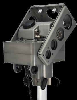
5 Description of items included with a LinkAlign-360FER The pictures and table below identify what is included with your LinkAlign-360FER Callout Callout Description number 1 LinkAlign-360FER positioner with embedded controller and web based user interface installed foot Power over Ethernet (PoE) power and control cable. Connects between the LinkAlign antenna positioner and item 4 PoE power injector 3 AC power cable for Power over Ethernet (PoE) supply. 4 56VDC 56Watt PoE power supply. LinkAlign-360FER Details The pictures and table below identify and describe each feature of the LinkAlign-360FER positioner. Additional details can be found in the LinkAlign-360FER mechanical ICD (ICDN900316) Bottom View Installed on Pole Proprietary, Nextmove Technologies Page 5
6 Callout Callout Description number 1 Power Over Ethernet (PoE) connector, Outdoor weather proof circular RJ Pin weather tight connector for optional RS-485 serial interface. 3 T-Handle tool-less pole mount fasteners located in two places. Provides primary tension against two inch pole mount for installation. 4 LinkAlign pole mount interface, 2 Inch inner diameter pole mount socket with 3.5 inch socket depth. 5 1/4-20 threaded holes in 4 places to allow for additional customer mounting requirements 6 Alignment/Anti rotation pin. Allows positioner to be pinned to the two inch mounting pole. 7 Antenna mount interface for installation of antenna or customer payload. See LinkAlign-360FER mechanical ICD identified as ICDN for specific mounting surface dimensions and hole locations. Nextmove also has antenna adapter brackets to work with many commercially available antennas. Visit the Nextmove website at for more information on antenna adapter brackets. 8 Four 1/4-20 captive nuts. Interface to LinkAlign quick mount antenna adapter brackets for rapid tool-less installation of antenna payloads. 9 GPS Antenna used by the LinkAlign software to establish current location position weather tight connector for optional polarization rotator. 11 GPS connector. Provides power and data to external GPS puck. 12 Connector guard and cable management bracket. Provides protection to Ethernet and Serial cables and provides holes to route other RF or Data cables attached to antenna payload mount surface. Proprietary, Nextmove Technologies Page 6
7 Steps for Setup and Operation of the LinkAlign-360FER antenna positioner Step 1, Install LinkAlign-360FER Mount the LinkAlign positioner to a 2 inch pole and tighten T handles at back of unit. Fasten T-Handles to secure to pole Optional captive plunger style pin may be used Place positioner on top of two inch O.D. pole. See FER ICD drawing number ICDN for more details. Step 2, Connect control cable. Connect weather tight quarter turn circular connector end of the PoE Ethernet control cable to LinkAlign positioner as shown below. PoE cable shown connected to LinkAlign-360FER Proprietary, Nextmove Technologies Page 7

8 Step 3, Connect PoE control cable to PoE injector Connect opposite end of Ethernet control cable to the Data & Power Out side of PoE injector as shown below. Plug the AC power side of the PoE injector into a standard VAC single phase 50-60Hz power source. Data & Power Out PoE Cable from Positioner Step 4, Connect PoE injector to Computer. Connect data side of PoE injector to a computer using a standard Ethernet cable with RJ-45 connectors at each end. This cable is not supplied with positioner. Proprietary, Nextmove Technologies Page 8


9 Step 5, Configure your computer IP address Configure your wired Ethernet RJ-45 connection on your computer for a static IP address. The LinkAlign antenna positioner uses the default IP address of Set the computer static IP address at as shown below. Configuring customer supplied computer for a static IP address will vary with each computer operating system. An example using windows is shown below. Step 6, Access control window using web browser. Log on to positioner using Google Chrome, Safari, or Mozilla Firefox. Enter the factory set static IP Proprietary, Nextmove Technologies Page 9


10 address of into the command line of the web browser. An authentication required window will appear in the browser as shown below. Enter the factory default user name and password called out below and select the "OK" button. Nextmove default User Name and Password. User Name: admin Password: nextmove The User Interface main page will load into the browser window indicating that you are now connected to the LinkAlign antenna positioner. The table below identifies and describes each control window Proprietary, Nextmove Technologies Page 10
11 Callout number Callout Description 1 Manual Control Window: Provides manual slew and step size control for manual up, down, clockwise, and counter clockwise commands. Optional polarization rotation is provided when installed. 2 Pedestal Position Window: Displays the antenna pedestals current antenna position for azimuth and elevation. Allows entry of target azimuth, elevation, and optional polarization angles. 3 Auto Peak: LinkAlign interfaces to many commercial radios and will pull the Receive Signal Strength Indication (RSSI) from the radio and use this information to peak static links to maintain the highest Quality of Service or track moving targets such as ships or aircraft. 4 Stored Locations: Allows user defined entry of Azimuth and Elevation pairs or Latitude and Longitude pairs to quickly recall and return to stored entry point. 5 Settings Button: The settings button will open a separate window which allows for configuration of IP address, positioner travel limits, software version, and software updates. 6 GPS Window: Displays current latitude and longitude of antenna positioner and allows manual entry for desired target latitude and longitude. The GPS window also allows users to upload a CSV file direct from Pathloss that stores microwave link locations to the Stored Locations database window. 7 Map Window: Provides a visual representation of the both ends of the link. The map is default centered around the local end. The map window also displays the antenna positioner heading. Proprietary, Nextmove Technologies Page 11

12 LinkAlign User interface details This section details each user control window on the main page and describes the command and status function available in each window. Manual Controls window with "Step" Function enabled Callout Callout Callout Function number Description 1 Step/Slew select This button allows the user to select between step or slew command control. The functions outlined in this table identify how the positioner will respond with "Step" selected in the manual controls window. 2 Up Arrow Moves the LinkAlign elevation antenna position in a positive direction (up) in step sizes equal to the defined step size. Each time the arrow is pressed the positioner will move by the defined step size amount and then stop. The positioner will continue to accept this command until the travel limit in this direction is met. 3 Counter Clockwise Arrow Moves the LinkAlign azimuth antenna position in a counter clockwise direction in step sizes equal to the defined step size. Each time the arrow is pressed the positioner will move by the defined step size amount and then stop. The positioner will continue to accept this command until the travel limit in this direction is met. 4 Clockwise Moves the LinkAlign Polarization antenna position in a Proprietary, Nextmove Technologies Page 12
13 Polarization rotator control clockwise rotation equal to the defined step size. Each time the button is pressed the polarization axis will move by the defined step size amount and then stop. The positioner will continue to accept this command until the travel limit in the clockwise polarization direction is met. (This control will only work if a polarization rotator is installed) 5 Speed control The speed control slider bar selects the velocity of the antenna positioner. The far right as shown in the manual is the fastest and the far left is the slowest. The slider bar has 4 speed locations. The speed control slider bar can change the positioner velocity range from 2º/sec, 3.75º/sec, 5º/sec, and 7 deg per second. 6 Emergency Stop button 7 Step size selection 8 Clockwise Arrow 9 Counter Clockwise Polarization rotator control The emergency stop button will stop travel in all directions when selected. Allows user defined steps sizes in degrees. User configurable step sizes are entered and the value is applied to manual arrow direction commands. Example shows 5 degrees per step. Moves the LinkAlign azimuth antenna position in a clockwise direction in step sizes equal to the defined step size. Each time the arrow is pressed the positioner will move by the defined step size amount and then stop. The positioner will continue to accept this command until the travel limit in this direction is met. Moves the LinkAlign Polarization antenna position in a counter clockwise rotation equal to the defined step size. Each time the button is pressed the polarization axis will move by the defined step size amount and then stop. The positioner will continue to accept this command until the travel limit in the counter clockwise polarization direction is met. (This control will only work if a polarization rotator is installed) 10 Down Arrow Moves the LinkAlign elevation antenna position in a negative (down) direction in step sizes equal to the defined step size. Each time the arrow is pressed the positioner will move by the defined step size amount and then stop. The positioner will continue to accept this command until the travel limit in this direction is met. Proprietary, Nextmove Technologies Page 13

14 Manual Controls window with "Slew" Function enabled Callout Callout Callout Function number Description 1 Step/Slew select This button allows the user to select between step or slew command control. The functions outlined in this table identify how the positioner will respond with "Slew" selected in the manual controls window. 2 Up Arrow Moves the elevation axis antenna position in a positive direction (up). Press and hold the up arrow and the positioner will continue to move in an upwards direction until the travel limit is met or the directional arrow is released. 3 Counter Clockwise Arrow Moves the azimuth antenna position in a counter clockwise direction (left). Press and hold the CCW arrow and the positioner will continue to move in an CCW direction until the travel limit is met or the directional 4 Clockwise Polarization rotator control arrow is released. Moves the polarization antenna position in a clockwise direction. Press and hold the clockwise polarization button and the positioner will continue to move in an clockwise direction until the travel limit is met or the directional arrow is released. (This control will only work if a polarization rotator is installed) 5 Speed control The speed control slider bar selects the velocity of the antenna positioner. The far right as shown in the manual is the fastest and the far left is the slowest. The slider bar Proprietary, Nextmove Technologies Page 14
.")
15 6 Emergency Stop button 7 Clockwise Arrow 8 Counter Clockwise Polarization rotator control has 4 speed locations. The speed control slider bar can change the positioner velocity range from 2º/sec, 3.75º/sec, 5º/sec, and 7 deg per second. The emergency stop button will stop travel in all directions when selected. Moves the azimuth antenna position in a clockwise direction (right). Press and hold the CW arrow and the positioner will continue to move in an CW direction until the travel limit is met or the directional arrow is released. Moves the polarization antenna position in a counter clockwise direction. Press and hold the counter clockwise polarization button and the positioner will continue to move in an counter clockwise direction until the travel limit is met or the directional arrow is released. (This control will only work if a polarization rotator is installed) 9 Down Arrow Moves the elevation antenna position in a negative direction (down). Press and hold the down arrow and the positioner will continue to move in the down direction until the travel limit is met or the directional arrow is released. Pedestal Position window Callout Callout Callout Function number Description 1 Current Displays LinkAlign positioners current azimuth heading Proprietary, Nextmove Technologies Page 15

16 Azimuth in degrees. Position 2 Current Elevation Displays LinkAlign positioners current elevation heading in degrees. Position 3 Current Polarization Displays positioners current polarization angle in degrees. (If a polarization rotator is installed) Position 4 "Go" button Executes commanded Azimuth, Elevation, and Polarization entries. An operator may enter values into one or all of the command boxes and press the "Go" button. The positioner will move until the current position is equal to the "Target" values entered. 5 Commanded Azimuth Position 6 Commanded Elevation Position 7 Commanded Polarization Position Accepts values in degrees to command the positioner to a desired azimuth angle. Accepts values in degrees to command the positioner to a desired elevation angle. Accepts values in degrees to command the polarization rotator to a desired polarization angle. (Requires polarization rotator (LinkAlign-360POL) to be installed) 8 Active Axis lights Indicates if an axis is active. Red = stopped (no motion) Green = go (axis in motion). 9 "Store" button Allows the current Azimuth and Elevation to save to "Stored Locations" database. Stored Locations window Proprietary, Nextmove Technologies Page 16


17 Callout Callout number Description 1 Az/El Stored location 2 Lat/Long Stored location Callout Function Stores as a green entry. A new Az/El will enter the stored locations database each time the "Store" button is pressed on the "Pedestal Position" window. Example shows "Stow Position" at 0.0º Azimuth and 90.0º Elevation. Stores as a blue entry. A new Lat/Long will enter the stored locations database each time the "Store" button is pressed on the "GPS" window. Example shows "South Tower Site" at N latitude and W Longitude. 3 Scroll Bar Allows user to scroll through entire list of stored locations. 4 "Save Stored Location" pop up window Once a user has pressed the "Store" button from either the "Pedestal Position" window or the "GPS" window, the "Save Stored Location" window will pop up on the 5 Stored Location title display. This can be any name that helps you remember a stored location. The Stored location title should be a unique name for each entry. Example used above is "Example Proprietary, Nextmove Technologies Page 17

18 stored Az/El" 6 Location Index The stored location database will store up to 40 unique locations. The location index will default you to the next empty location to store your new entry. Once you have reached 40 entries you must select a location within the database to overwrite should you ever reach the maximum stored entry locations. 7 Az/El or Lat/Long to be saved This field identifies the Az/El angles or Lat/Long coordinates that will be stored to the Location Database. The example here shows that a º Azimuth and º Elevation will be saved at Location index 4 as "Example stored Az/El". 8 "Store" button The store button will save the data in each field and add to the "Stored Location" window. 9 "Cancel" button The cancel button will close the "Save Stored Location" pop up window and will not add any data to "Stored Location" window. 10 Example Stored Location If the "Store" button is pressed the data will be added to the "Stored Locations" window as shown above as "Example stored Az/El". You may double click on the location in the database and the LinkAlign system will move to that location. A right click will allow you to delete the location from the "Stored Locations" window. GPS window Proprietary, Nextmove Technologies Page 18
19 Callout Callout number Description 1 Current Coordinates 2 Altitude and number of Satellites Callout Function Displays the current GPS coordinates read from the antenna positioner. Displays additional GPS data identifying current altitude of the positioner and the number of satellites in view. 3 GPS Status Four color LED indicating current GPS status. Green = GPS online and working properly, Yellow = GPS is reporting data but is still collecting data to report accurate fix, Blue = GPS is reading data but GPS data is not valid, and Red indicates that GPS is not communicating with the LinkAlign antenna positioner. 4 Upload Stored Locations 5 Target Coordinates The "Upload Stored Locations" allows you to directly upload a stored CSV file created in Pathloss or Microsoft Excel. The CSV file must consist of specific column headers for "Site name", "Latitude", and "Longitude". The target coordinates allows user entry of the target Latitude and Longitude position. The user may also browse the map and select a location which will result in an auto populate of the target end latitude and longitude. 6 Bearing Angle Displays the calculated azimuth heading angle to the Target Coordinates. Once a target coordinate is entered the bearing angle will populate a heading. 7 Ground Distance Displays the line of sight ground distance between the current coordinates and target coordinates entered in the GPS window. Once a target coordinate is entered the ground distance will display the calculated distance between the two coordinates. 8 "Store"button Allows the current Lat/Long displayed in the "Target Coordinates" (Callout #5) to be saved to the "Stored Locations" database. 9 "Go" button The "Go" button will point the antenna positioner at the target GPS coordinates. The positioner uses its current location and target GPS coordinates to calculate a line of bearing to the target end. Proprietary, Nextmove Technologies Page 19

20 Auto Peak window The Auto Peak function requires a Radio Signal Strength feedback loop between the LinkAlign antenna positioner and the installed radio. Contact Nextmove for a full list of Auto Peak enabled radio solutions Callout Callout Callout Function number Description 1 "Seek" button The seek button executes a secondary radio acquisition method. The primary LinkAlign Acquisition strategy is to place target Lat/Long values and use the on board compass to locate the opposite end of the link. If for some reason this data is unavailable, the seek function is good fall back option. The seek function scans an area and searches for a link using only RF energy detect. It requires the user to enter a Start Angle (callout #9), Scan Width (callout #10), Step Size (callout #11), and Dwell time (callout #12) to execute the seek function. 2 "Peak" button Executes an auto peak function to locate the highest signal and maintain highest Quality of Service (QoS). 3 RSSI: value Reports current Receive Signal Strength Indication (RSSI) from radio. 4 BPS: value Reports current Bits Per Second data rate of the radio. 5 In Prog: LED The "In Prog" (short for in progress) reports when a peak or seek is in progress. Red indicates no activity and green led indicates in progress. Proprietary, Nextmove Technologies Page 20

21 6 "Continuous" button Places the peak process into a continuous peaking mode of operation. This is often used in active tracking when one or both ends of the link are on moving platforms such as a ship. The unit will continuously peak at a set time interval that is set under the "Settings" button (Callout #8). 7 "Peak Az Only" Removes elevation peaking from tracking algorithm. 8 "Settings"button Opens the Radio Settings page. Set's the communications method between the radio and LinkAlign positioner to Serial or Ethernet. A drop down menu of available interfaces allows selection of Radio manufacturer. The active request is a yes/no which sets if the LinkAlign must request RSL of if it is simply broadcasted continuously from the radio. If the LinkAlign positioner is communicating via Ethernet a Radio IP address field is available to identify the radios IP address. The continuous Peak sets the time interval if continuous peaking mode is active (Callout #6). 9 "Start Angle" command box 10 "Scan Width" command box 11 "Step Size" command box 12 "Dwell Time" command box Sets the center (Start) position of the scan width used for the "seek" process. In the example shown, a start angle of 0 and scan width of 45 deg would scan from to centered around 0 deg. Sets the scan width used for the "seek" command. Sets the step size used for both seek and peak tracking steps. Sets the dwell time between step sizes. Proprietary, Nextmove Technologies Page 21

22 Map Window Callout Callout Callout Function number Description 1 Map Area The map area is populated by Google maps. The current GPS coordinates are used to center the map and identify its surroundings. The map area can be turned off by deselecting the "use Google" check box on the settings page. 2 LinkAlign local side positioner marker The LinkAlign local side position marker is red. It identifies the current location of the LinkAlign antenna positioner on the map and provides visual representation 3 LinkAlign target side positioner marker to the desired target end location. The LinkAlign target side positioner marker is green. It identifies the current location of the target side LinkAlign antenna positioner on the map and provides visual representation to the desired local end location. 4 Map Zoom Allows the map window to zoom in or out. Proprietary, Nextmove Technologies Page 22
23 slider bar 5 Positioner Heading 6 Magnetic/True North Switch 7 Compass Override 8 "Calibrate Compass" button Displays the local side LinkAlign antenna positioner heading. Changes the compass heading between true north or magnetic north heading. If magnetic north is selected the positioner uses the on board compass and displays current magnetic heading. If True North is selected the positioner uses data from the GPS to update the compass and apply a magnetic declination to use true north compass heading. A compass override button allows the magnetic compass to be ignored and use the fixed heading entered in the compass override box. The magnetic compass is factory calibrated for the local magnetic environment. If the compass becomes unstable it is most likely that the magnetic environment has changed enough to affect the compass accuracy. If the compass becomes unstable the "Calibrate compass" button will allow for new magnetic environment measurements to be taken and stored to restore normal operation. The "In Prog" LED will go from red to green during a calibration. The LinkAlign positioner will move 360 degrees and stop 6 times to take readings at different azimuth locations. Take care to make sure the unit has no physical obstructions during this process. If the SW limits have been set to reduce travel less than 360 degrees the unit will attempt to calibrate using only the set azimuth range. It is highly recommended that the full range is used for calibration to produce the best results. Proprietary, Nextmove Technologies Page 23
.")
24 Settings Page This section details the settings page. The settings page is a pop up window that is opened by selecting the gear button in the upper right side of the main control page (Identified below as callout number 1). Once visible, the settings page (Identified below as callout number 2) allows updates to the system. Full details of the settings page are provided below. 1 2 Callout number Callout Description 1 Settings Page button: Launches the settings window (callout number 2 above) 2 Settings window: Allows user input to configuration items and provides status on current system settings. Proprietary, Nextmove Technologies Page 24

25 Callout Callout Callout Function number Description 1 Limits User configurable travel limits. All entries are in degrees. Allows software adjustment to travel limits in Azimuth, Elevation, and optional Polarization axis. The default travel limits for each axis is the maximum physical travel limits. The "save settings" button must be selected before updates are applied. 2 IP Settings User configurable IP address settings for the LinkAlign antenna positioner. Each LinkAlign positioner also has a non configurable IP address to access the system in case the primary IP address is lost or forgotten. See the IP Reset instructions for more information. The "save settings" button must be selected before updates are applied. 3 Users Allows users to be added or deleted. There must be at least one user to allow login to the system. The default user is "admin" with the password of "nextmove". The password may be changed or the entire user deleted. 4 Add New Allows new users to be added. 5 Serial Number Displays the LinkAlign antenna positioner serial number. Proprietary, Nextmove Technologies Page 25
26 This field is non configurable and is the unique identifier used by Nextmove to track warranty and software revisions. 6 Reboot Forces the on board CPU to reboot. 7 NMT debugging info checkbox This is normally for factory use only. A Nextmove phone support engineer may ask you to check this box to display real-time analog and digital values used to control and monitor the system. 8 Firmware Version Display's the current software revision running on the LinkAlign digital controller. 9 "Choose File" button Allows the user to browse for a file to upload new software to the LinkAlign antenna positioner. 10 "Upload" button The upload button will load the file selected by the user. 11 "Set Pol Zero" button 12 "Clear Pol Zero" button 13 Enable Polarization Axis 14 LinkAlign System status The "Set Pol Zero" button will identify the polarization current position as its zero position. Depending on the pol rotators current position, this may limit the travel in one direction and increase in the opposite. For example, if the "set pol zero was selected at 200 degrees the pol rotator would now have 20 degrees of clockwise direction and 420 degrees of counter clockwise direction. The "save settings" button must be selected before updates are applied. The "Clear Pol Zero" button will restore the factory zero location at the center of physical travel (±220º). The "save settings" button must be selected before updates are applied. Enables or disables the polarization axis. Polarization control is only necessary if a Polarization axis is purchased with the system. Displays last action details for user review during configuration changes. 15 "Exit" button The "Exit" button will close the settings window and 16 "Save Settings" button 17 "Use Google" check box return to the main control page. The "Save settings" button will save any updates made to the user configurable settings in the settings window. Check box to allow the user interface to populate the topographical map in the map window. If left unchecked the map will not load but still display both ends of the link in the map area window. The "save settings" button must be selected before updates are applied. Proprietary, Nextmove Technologies Page 26


27 IP Reset instructions The LinkAlign antenna positioner has a permanent IP address that is always accessible with the proper setup of your computers IP address settings. This IP address can be used to access the system and recall the current IP address settings or make other changes. It is important to follow the instructions below carefully as this IP reset address is not recognized by standard routers or switches. Step 1, Go to your computers TCP/IPv4 adapter settings and re-configure your computers IP network settings. You must use the specific IP address and subnet mask identified below. The positioner is setup to look for this specific routing and will not communicate if other IP addresses are used. Set your computer IPv4 properties to the following: Set a static IP address of: Set a subnet mask of: Select Ok to accept new settings Step 2, Connect the LinkAlign antenna positioner directly to the laptop or computer that has been reconfigured as shown below. The positioner should not have any routers or switches in line as most routers or switches do not recognize a 169 network and will not forward requests or status associated with this number range. 48VDC Power Configuration setup for IP Reset Step 3, Using any web browser type the IP address into the web browser command line Proprietary, Nextmove Technologies Page 27

28 as shown below. The standard web browser control window for the LinkAlign antenna positioner will launch. The settings window can now be accessed to view the current IP settings for the unit or entry of new IP address can be made and saved to allow operation on your network. Proprietary, Nextmove Technologies Page 28
29 LinkAlign Connector Pin outs Power over Ethernet (PoE) connector Mating Connector RJ45 Modular / CAT5 / 8 Pin / Male Mating Circular Shell Manufacturer Amphenol part number RJF6B Power over Ethernet (PoE) pin out Pin number Description 1 Data Pair 1 2 Data Pair 1 3 Data Pair to 56VDC PoE power input to 56VDC PoE power input 6 Data Pair 2 7 DC return for PoE input 8 DC return for PoE input RS-485 Serial Interface connector Mating Connector Manufacturer Turck, Part number BS /PG9 RS-485 serial pin out Pin number Description 1 Twisted pair minus ( - ) RS-485 termination, typically tied to B or D- data line 2 Twisted pair positive ( + ) RS-485 termination, typically tied to A or D+ data line 3 (B) TxD+/RxD+ data line 4 (A) TxD-/RxD- data line 5 Not Used GPS RS-232 connector Mating Connector Manufacturer Turck, Part number BS /PG9 GPS RS-232 pin out Pin number Description 1 Signal Ground 2 +5VDC for GPS power 3 Serial RS-232 Rx Data 4 Serial RS-232 Tx Data 5 GPS 1PPS Proprietary, Nextmove Technologies Page 29
30 Polarization rotator connector Mating Connector Manufacturer Turck, Part number BS /PG9 Polarization rotator pin out Pin number Description 1 Ground 2 Motor Drive + 3 Motor Drive - 4 Potentiometer Wiper 5 3.3VDC Proprietary, Nextmove Technologies Page 30
LinkAlign-60RPT Set-up and Operation Manual
 LinkAlign-60RPT Set-up and Operation Manual LinkAlign Setup and Operation Proprietary, Nextmove Technologies Page 1 LinkAlign Setup and Operation Proprietary, Nextmove Technologies Page 2 Description of
Products overview. Auto Point Antenna Alignment Solutions
 Products overview Auto Point Antenna Alignment Solutions About Nextmove Design house and Manufacturer of auto antenna alignment products serving: Commercial communications Emergency Management Military
AW2400iTR USER S MANUAL 2.4 GHz Indoor Wireless Ethernet Radio
 USER S MANUAL 2.4 GHz Indoor Wireless Ethernet Radio Industrial-grade, long-range wireless Ethernet systems AvaLAN W I R E L E S S Thank you for your purchase of the AW2400iTR Indoor Wireless Ethernet
AW5802xTP. User s Manual. 5.8 GHz Outdoor Wireless Ethernet Panel. AvaLAN. Industrial-grade, long-range wireless Ethernet systems
 5.8 GHz Outdoor Wireless Ethernet Panel Industrial-grade, long-range wireless Ethernet systems AvaLAN W I R E L E S S Thank you for your purchase of the AW5802xTP 5.8 GHz Outdoor Wireless Ethernet Panel.
GPSR400 Quick Start Guide
 GPSR400 Quick Start Guide Rev. 6 Introduction Microlab s digital GPS repeater system can be used for cellular communications UTC synchronization for locations where the GPS signals are not readily available.
AW58300HTA AW58300HTS USER S MANUAL
 AW58300HTA AW58300HTS USER S MANUAL 5.8 GHz Outdoor 300 Mbps Wireless Ethernet Access Point and Subscriber Unit Radios Industrial-grade, long-range wireless Ethernet systems AvaLAN W I R E L E S S The
Connecting the Radio:
 Connecting the Radio: Step 1: Connect the Cat5 cable from the radio into the RJ-45 jack marked CPE on the POE injector. The POE injector is not weather proof and should be installed indoors. Step 2: Connect
AW5802xTR. User s Manual. 5.8 GHz Outdoor Wireless Ethernet Radio. AvaLAN. Industrial-grade, long-range wireless Ethernet systems
 AW5802xTR 5.8 GHz Outdoor Wireless Ethernet Radio Industrial-grade, long-range wireless Ethernet systems AvaLAN W I R E L E S S Thank you for your purchase of the AW5802xTR 5.8 GHz Outdoor Wireless Ethernet
AW900xTR USER S MANUAL 900 MHz Outdoor Wireless Ethernet Radio
 USER S MANUAL 900 MHz Outdoor Wireless Ethernet Radio Industrial-grade, long-range wireless Ethernet systems Thank you for your purchase of the AW900xTR Outdoor Wireless Ethernet Radio. The AW900xTR includes:
AW900-SPEC USER S MANUAL
 USER S MANUAL 900 MHz Site Survey Spectrum Analyzer Industrial-grade, long-range wireless Ethernet systems AvaLAN W I R E L E S S User s Manual Thank you for your purchase of the AW900-SPEC Site Survey
AvaLAN AW58103HTS MANUAL ADDENDUM. 5.8 GHz Outdoor 100 Wireless 3-Port Ethernet Subscriber Unit Radio
 AW58103HTS MANUAL ADDENDUM 5.8 GHz Outdoor 100 Wireless 3-Port Ethernet Subscriber Unit Radio Industrial-grade, long-range wireless Ethernet systems AvaLAN W I R E L E S S AW58103HTS Addendum The AW58103HTS
AW5800-SPEC USER S MANUAL
 USER S MANUAL 5.8 GHz Site Survey Spectrum Analyzer Industrial-grade, long-range wireless Ethernet systems AvaLAN W I R E L E S S User s Manual Thank you for your purchase of the AW5800-SPEC Site Survey
C-COM Satellite Systems Inc. Page 1 of 39
 Page 1 of 39 inetvu Fly-75V & Fly-98G/H/V & Fly-981 User Manual The inetvu brand and logo are registered trademarks of C-COM Satellite Systems, Inc. Copyright 2006 C-COM Satellite Systems, Inc. 1-877-iNetVu6
3 GHz Carrier Backhaul Radio. Model: AF-3X. Tel: +44 (0) Fax: +44 (0) LINK GPS MGMT DATA DATA
 Fax: +44 (0) LINK GPS MGMT DATA DATA") LINK GPS MGMT DATA DATA MGMT GPS LINK 3 GHz Carrier Backhaul Radio Model: AF-3X LINK GPS MGMT DATA 3 GHz Carrier Backhaul Radio Model: AF-3X LINK GPS MGMT DATA DATA MGMT GPS LINK Introduction Thank you
LINK GPS MGMT DATA DATA MGMT GPS LINK 3 GHz Carrier Backhaul Radio Model: AF-3X LINK GPS MGMT DATA 3 GHz Carrier Backhaul Radio Model: AF-3X LINK GPS MGMT DATA DATA MGMT GPS LINK Introduction Thank you
GPSR116 Quick Start Guide
 GPSR116 Quick Start Guide .21 [ 5,3] [482,6] 18.12 [460,3] GPSR116 Quick Start Guide Rev 2.35 [8,9] Introduction Microlab s digital GPS repeater system can be used for cellular communications UTC synchronization
USER S MANUAL ADDENDUM Matched Pair Bridges
 USER S MANUAL ADDENDUM Matched Pair Bridges Certain AvaLAN radios are sold as matched pairs, pre-configured as a wireless Ethernet bridge. The manual supplied with the pair does not include information
Installation Guide. Hiltron Motorized Antenna Mount HMAM
 HMAM_Install_A.doc Page 1 of 20 Installation Guide for Hiltron Motorized Antenna Mount HMAM HMAM_Install_A.doc Page 2 of 20 Table of Contents 1 Overview...3 2 Unpacking and Inspection...3 3 Contents of
Antenna Pointing Guide
 Antenna Pointing Guide 1039429-0001 Revision B September 10, 2013 11717 Exploration Lane, Germantown, MD 20876 Phone (301) 428-5500 Fax (301) 428-1868/2830 Copyright 2013 Hughes Network Systems, LLC All
LINK GPS MGMT DATA. 4 GHz Licensed Backhaul Radio DATA MGMT GPS. Model: AF-4X LINK
 LINK GPS MGMT DATA DATA MGMT GPS LINK 4 GHz Licensed Backhaul Radio Model: AF-4X 4 GHz Licensed Backhaul Radio Model: AF-4X LINK GPS MGMT DATA DATA MGMT GPS LINK Introduction Thank you for purchasing the
Antenna Control Unit (ACU) Graphical User Interface (GUI) Software Instruction Manual
 Graphical User Interface (GUI) Software Instruction Manual") ISO 9001:2015 Certified Antenna Control Unit (ACU) Graphical User Interface (GUI) Software Instruction Manual Quasonix, Inc. 6025 Schumacher Park Dr. West Chester, OH 45069 19 July 2018 Revision 1.5 Software
ISO 9001:2015 Certified Antenna Control Unit (ACU) Graphical User Interface (GUI) Software Instruction Manual Quasonix, Inc. 6025 Schumacher Park Dr. West Chester, OH 45069 19 July 2018 Revision 1.5 Software
AW900F AW900F-PAIR USER S MANUAL
 AW900F AW900F-PAIR USER S MANUAL 900 MHz Industrial Wireless Ethernet Radios Industrial-grade, long-range wireless Ethernet systems AvaLAN W I R E L E S S Thank you for your purchase of the AW900F Indoor
IG-2500 OPERATIONS GROUND CONTROL Updated Wednesday, October 02, 2002
 IG-2500 OPERATIONS GROUND CONTROL Updated Wednesday, October 02, 2002 CONVENTIONS USED IN THIS GUIDE These safety alert symbols are used to alert about hazards or hazardous situations that can result in
TT-208. User s Manual. 300Mps 5.8 GHz. IP Camera Wireless Transmission Kit
 TT-208 300Mps 5.8 GHz IP Camera Wireless Transmission Kit User s Manual V1.0 02 / 2014 Welcome Thank you for purchasing the TT-208 Wireless Transmission Kit for IP Cameras. This user s manual is designed
11 GHz FDD Licensed Backhaul Radio. Model: AF 11FX
 11 GHz FDD Licensed Backhaul Radio Model: AF 11FX 11 GHz FDD Licensed Backhaul Radio Model: AF 11FX Introduction Thank you for purchasing the Ubiquiti Networks airfiber AF 11FX. This Quick Start Guide
MPR kHz Reader
 MPR-5005 Page 1 Doc# 041326 MPR-5005 125kHz Reader Installation & Operation Manual - 041326 MPR-5005 Page 2 Doc# 041326 COPYRIGHT ACKNOWLEDGEMENTS The contents of this document are the property of Applied
MESA-HPX. Assembly and Installation Manual. w/appendix A for Prodelin Antenna. 901-Manual-MESA-HPX
 MESA-HPX Assembly and Installation Manual w/appendix A for Prodelin Antenna 901-Manual-MESA-HPX Rev 30 March 2011 2 INDEX Installation Cautions 4 Installation Pole Height Orientation of the Mount on the
RC3000/ RC3050 INTERFACE SPECIFICATIONS
 RC3000/ RC3050 INTERFACE SPECIFICATIONS Research Concepts, Inc.; Lenexa, KS 66215; PH: (913)469-4125; FAX: (913)469-4168 WWW.RESEARCHCONCEPTS.COM SUPPORT@RESEARCHCONCEPTS.COM Overview The RC3000 Satellite
AC and DC solutions- Multiple AC and DC solutions available, please contact factory for your application.
 The ATX-3000 antenna tracking controller is a user-friendly microprocessor-based intelligent positioning system to reliably track inclined orbit satellites or for use as a positioner for geosynchronous
rino 600 series quick start manual
 rino 600 series quick start manual Getting Started Keys warning See the Important Safety and Product Information guide in the product box for product warnings and other important information. When using
QDV120 Operation and Pointing manual
 QDV120 Operation and Pointing manual MPAD1 Plus OP-080316-E1 page 1 Contents Item Description Page 1.0 Health and Safety for Operators and Installation Staff 3 2.0 Transit case Reflector/Mount/BUC/LNB
AA-35 ZOOM. RigExpert. User s manual. Antenna and cable analyzer
 AA-35 ZOOM Antenna and cable analyzer RigExpert User s manual . Table of contents Introduction Operating the AA-35 ZOOM First time use Main menu Multifunctional keys Connecting to your antenna SWR chart
Ground System Training Department
 Module 7: IPSTAR Uplink Access Test (IUAT) Ground System Training Department 2012-03-Standard (iuat1.14)-uti-101 THAICOM Public Company Limited Module Objectives At the end of the module the participant
PAP-240 Three Axis Antenna Pedestal and feed drive
 Présentation générale. ANTENNE MOTORISEE 3 AXES Versions : RxO Ku, RxO Ku&C (4 ports), RxTx Ku (2 ports), RxTx C (2 ports) PAP-240 Three Axis Antenna Pedestal and feed drive The two axis Motorized antenna
APPENDIX B - MOUNT SPECIFIC DATA for the Vertex 1.8m. FlyAway
 RC3000 Antenna Controller Appendix B Mount Specific Data 1 APPENDIX B - MOUNT SPECIFIC DATA for the Vertex 1.8m. FlyAway Revision: 14 December 2009, Software Version 1.60 1.1 Appendix B Organization This
BRU-100 Physical Installation
 APPENDIX B BRU-100 In This Appendix: Warnings and Cautions, page 50, page 51 Check List, page 57 This appendix provides guidance for the physical installation of the BRU-100 Remote Unit at a subscriber
XLR PRO Radio Frequency (RF) Modem. Getting Started Guide
 Modem. Getting Started Guide") XLR PRO Radio Frequency (RF) Modem Getting Started Guide XLR PRO Radio Frequency (RF) Modem Getting Started Guide 90002203 Revision Date Description A September 2014 Initial release. B March 2014 Updated
XLR PRO Radio Frequency (RF) Modem Getting Started Guide XLR PRO Radio Frequency (RF) Modem Getting Started Guide 90002203 Revision Date Description A September 2014 Initial release. B March 2014 Updated
M-0418 REV:0
 1 of 5 This specification sets forth the minimum requirements for purchase and installation of an aboveground Radar Detection Device (RDD) system for a real-time, stop bar vehicle-detection system that
Quick Start Guide. RSP-Z2 Dual Channel Analog-IP Interface
 INTEROPERABILITY NOW Quick Start Guide RSP-Z2 Dual Channel Analog-IP Interface Designed and Manufactured by: JPS Interoperability Solutions 5800 Departure Drive Raleigh, NC 27616 919-790-1011 Email: sales@jpsinterop.com
Featherweight GPS Tracker User s Manual June 16, 2017
 Featherweight GPS Tracker User s Manual June 16, 2017 Hardware Configuration and Installation The dimensions for the board are provided below, in inches. Note that with the antenna installed, the total
UCP-Config Program Version: 3.28 HG A
 Program Description HG 76342-A UCP-Config Program Version: 3.28 HG 76342-A English, Revision 01 Dev. by: C.M. Date: 28.01.2014 Author(s): RAD Götting KG, Celler Str. 5, D-31275 Lehrte - Röddensen (Germany),
Underwater GPS User Manual
 Underwater GPS Document number W-DN-17002-3 Project Classification - Rev Prepared by Checked by Approved by Short description 1 2017-08-03 T. Trøite O. Skisland T. Trøite Initial 2 2017-08-04 T. Trøite
ISONIC PA AUT Spiral Scan Inspection of Tubular Parts Operating Manual and Inspection Procedure Rev 1.00 Sonotron NDT
 ISONIC PA AUT Spiral Scan Inspection of Tubular Parts Operating Manual and Inspection Procedure Rev 1.00 Sonotron NDT General ISONIC PA AUT Spiral Scan Inspection Application was designed on the platform
75cm ODU/SurfBeam 2 Point and Peak Job Aid
 Summary This Job Aid covers: 75cm ODU/SurfBeam 2 Point and Peak Job Aid Preparing the Antenna for Pointing and Peaking Configure the SurfBeam 2 Modem and 75cm TRIA Point Elevation Set the Skew Point Azimuth
R5 RIC Quickstart R5 RIC. R5 RIC Quickstart CONTENTS. Saab TransponderTech AB. Appendices. Project designation. Document title
 Appendices 1 (10) Project designation R5 RIC Document title CONTENTS 1 Installation... 2 1.1 Connectors... 2 1.1.1 Power... 2 1.1.2 Video... 2 1.1.3 Sync... 3 1.1.4 RS232/ARP/ACP... 3 1.1.5 Radar data...
Rino. 650N series. quick start manual
 Rino 650N series quick start manual Getting Started warning See the Important Safety and Product Information guide in the product box for product warnings and other important information. When using your
Installation Guide. Suitable for: OEM Integration OEM Installation Retro Fit Installation
 Installation Guide Suitable for: OEM Integration OEM Installation Retro Fit Installation DTI AngleBlaster release 1.1 DTI 2010 Overview Angleblaster Installation Guide A-1 To obtain the best accuracy from
RC2000. Cable Preparation ACU Installation Troubleshooting/Alarm codes. Patriot 1.8m
 RC2000 Cable Preparation ACU Installation Troubleshooting/Alarm codes Patriot 1.8m Installation Instructions I. Needed equipment: Multimeter, small flathead screwdriver, large phillips screwdriver,
Kodiak Corporate Administration Tool
 AT&T Business Mobility Kodiak Corporate Administration Tool User Guide Release 8.3 Table of Contents Introduction and Key Features 2 Getting Started 2 Navigate the Corporate Administration Tool 2 Manage
Toughsat. Users Manual
 Toughsat Users Manual TOUGHSAT USERS MANUAL v.2.1 February 2012 Important warning regarding your Toughsat System ALL POWER to ALL system electronics MUST be disconnected if connecting the control cable
BFS / BFSM SERIES Installation & Maintenance Manual
 Introduction: The BFS / BFSM series electric actuators have battery backup modules for fail safe operation. The BFS series is for two position control and the BFSM series is for proportional control, both
Field Service Procedure Replacement Pol Motor Kit, Coastal
 1. Brief Summary: Troubleshooting document for diagnosing a fault with and replacing the pol motor on the Coastal series antennas. 2. Checklist: Verify Motor Drive Drive the Pol from Progterm Run the Built
High Security Supplement
 High Security Supplement User Manual Supplement foravalan Wireless Radios with FIPS 140-2 Security AW900FS USER S MANUAL Industrial-grade, long-range wireless Ethernet systems AvaLAN W I R E L E S S High
WARRANTY. Long Range Systems, LLC, 20 Canal St, Suite 4N, Franklin, NH 03235
 WARRANTY Long Range Systems, Inc. warrants the trap release product against any defects that are due to faulty material or workmanship for a one-year period after the original date of consumer purchase.
TAP 6 Demo Quick Tour
 TAP 6 Demo Quick Tour Sales Contact: Curt Alway P.O. Box 7205 Charlottesville, VA 22906 Voice: 303-344-5486, Ext 1 Fax: 303-265-9399 Email: sales@softwright.com Technical Contact: Todd Summers, Ph.D. P.O.
ExpoM - ELF User Manual
 ExpoM - ELF User Manual Version 1.4 ExpoM - ELF User Manual Contents 1 Description... 4 2 Case and Interfaces... 4 2.1 Overview... 4 2.2 Multi-color LED... 5 3 Using ExpoM - ELF... 6 3.1 Starting a Measurement...
RT-21 Az-El Controller Manual addendum to RT-21 - August 5, 2014
 RT-21 Az-El Controller Manual addendum to RT-21 - August 5, 2014 Overview: The RT-21 Az-El controller consists of two RT-21 units with a shared power supply and shared chassis. The unit features a pair
Software User Manual
 Software User Manual ElectroCraft CompletePower Plus Universal Servo Drive ElectroCraft Document Number: 198-0000021 2 Marin Way, Suite 3 Stratham, NH 03885-2578 www.electrocraft.com ElectroCraft 2018
HT1000 Satellite Modem Installation Guide
 HT1000 Satellite Modem Installation Guide 1039110-0001 Revision A October 17, 2012 11717 Exploration Lane, Germantown, MD 20876 Phone (301) 428-5500 Fax (301) 428-1868/2830 Copyright 2012 Hughes Network
Revision Date: 6/6/2013. Quick Start Guide
 Revision Date: 6/6/2013 Quick Start Guide Important Notice Copyright 2013Frontline Test Equipment. All rights reserved. i Important Notice Table of Contents Purpose 1 Minimum Hardware Requirements 1 Internet
Sealed Interface Control: EC20300
 ISO 9001:2000 WITH DESIGN Certificate #02.002.1 Sealed Interface Control: EC20300 FEATURES: Weather tight control package Pulse Width Modulated output Waterproof altitude pressure and vapor release vent
User Manual. This User Manual will guide you through the steps to set up your Spike and take measurements.
 User Manual (of Spike ios version 1.14.6 and Android version 1.7.2) This User Manual will guide you through the steps to set up your Spike and take measurements. 1 Mounting Your Spike 5 2 Installing the
ADI-100 Interrupter. Operator s Manual. 526 S. Seminole Bartlesville, OK /
 ADI-100 Interrupter Operator s Manual 526 S. Seminole Bartlesville, OK 74003 918/336-1221 www.sescocp.com ADI - 100 Interrupter FEATURES Clock Accuracy 100% during GPS lock Clock Drift 30 µsec per degree
WPE 48N USER MANUAL Version1.1
 Version1.1 Security instructions 1. Read this manual carefully. 2. Follow all instructions and warnings. 3. Only use accessories specified by WORK PRO. 4. Follow the safety instructions of your country.
LincView OPC USER GUIDE. Enhanced Diagnostics Utility INDUSTRIAL DATA COMMUNICATIONS
 USER GUIDE INDUSTRIAL DATA COMMUNICATIONS LincView OPC Enhanced Diagnostics Utility It is essential that all instructions contained in the User Guide are followed precisely to ensure proper operation of
Black Marlin radar systems may be purchased with a flat-top radome for mounting cameras on
 SPECIFICATIONS The Black Marlin is DMT s midrange security radar system. It may be used to search and track threats from land and sea. This radar is an X- Band, pulsed- Doppler system that operates in
Quick Start Guide. Contents
 1 Quick Start Guide Contents Powering on the Machine Login/Password Entry Jaw Set Up High Security Cut by Code High Security Jaw Set Up Edge Cut Cut by Code Edge Cut Cut by Decode Cutter Replacement Tracer
Installation Instructions
 Installation Instructions For 0.2m Ultra-high Performance Antenna Model ADxxG-0-T2 Before Installation, please read these instructions carefully. This instruction guide is for the installation of 8 inch
Series 70 Servo NXT - Modulating Controller Installation, Operation and Maintenance Manual
 THE HIGH PERFORMANCE COMPANY Series 70 Hold 1 sec. Hold 1 sec. FOR MORE INFORMATION ON THIS PRODUCT AND OTHER BRAY PRODUCTS PLEASE VISIT OUR WEBSITE www.bray.com Table of Contents 1. Definition of Terms.........................................2
1. Index. 1. Index 1 2. Important User Information Contact Information 2
 1. Index 1. Index 1 2. Important User Information 2 2-1. Contact Information 2 2-2. Warranty and Liability 2 2-3. About Instruction Manual 3 2-4. Environment 3 3. Safety Information 4 3-1. WARNING/CAUTION
RM600 Carrier Grade E1 Radios
 Carrier Grade E1 Radios Quick Start Guide Package Contents ODU 1 IDU 1 Mast/Wall Mounting Kit 1 Outdoor Ethernet Cable (Optional) 1 External Antenna (Optional) 1 Power Supply Cable 1 Quick Start Guide
SBS-3 SBS-1eR, SBS-1e and SBS-1
 BaseStation SBS-3 SBS-1eR, SBS-1e and SBS-1 Reference Manual Revision 3.1.2 25 September 2012 BaseStation Reference Manual Page 2 / 93 This device complies with part 15 of the FCC Rules. Operation is subject
AES 7705i MultiNet Receiver System Initial Installation and Setup Guide
 AES 7705i MultiNet Receiver System Initial Installation and Setup Guide AES Corporation 285 Newbury Street. Peabody, Massachusetts 01960-1315 USA Tel: USA (978) 535-7310. Fax: USA (978) 535-7313 Copyright
WCS-D5100 Programming Software for the Icom ID-5100 Data
 WCS-D5100 Programming Software for the Icom ID-5100 Data Memory Types (left to right) Memories Limit Memories DR Memories Call Channels GPS Memories Receive Frequency Transmit Frequency Offset Frequency
HAM RADIO DELUXE SATELLITES A BRIEF INTRODUCTION. Simon Brown, HB9DRV. Programmer- in- C hief
 HAM RADIO DELUXE SATELLITES A BRIEF INTRODUCTION Simon Brown, HB9DRV Programmer- in- C hief Last update: Sunday, September 26, 2004 User Guide The IC-703s and IC-7800s used in this project were supplied
Instruction Manual ABM HART Gateway Software. Instruction Manual Revision A.1
 Instruction Manual ABM HART Gateway Software Instruction Manual Revision A.1 Table of Contents Section 1: Getting Started... 3 1.1 Setup Procedure... 3 1.2 Quick Setup Guide for Ultrasonic Sensors... 11
Procedure, Field Replacement, PCU Kit, 6003A/6004, 2406 & 4003A
 1. Brief Summary: Troubleshooting document for diagnosing a fault with and replacing the PCU assembly on the 6003A/6004, 2406 & 4003A series antennas. 2. Checklist: Verify Initialization N0 Parameter Pedestal
LVTX-10 Series Ultrasonic Sensor Installation and Operation Guide
 LVTX-10 Series Ultrasonic Sensor Installation and Operation Guide M-5578/0516 M-5578/0516 Section TABLE OF CONTENTS 1 Introduction... 1 2 Quick Guide on Getting Started... 2 Mounting the LVTX-10 Series
Thuraya Orion IP Satellite Terminal. Maritime Installation Guide
 Thuraya Orion IP Satellite Terminal Maritime Installation Guide 3500867-0001 Revision 2 November 27, 2013 Copyright 2013 Hughes Network Systems, LLC All rights reserved. This publication and its contents
Print Head Installation Guide
 Print Head Installation Guide MCS Raptor 6 (MCS Eagle AMS Software) is copyright of MCS Incorporated. 2015 MCS Incorporated. 1 Contents Tools... 4 Warnings... 4 Introduction... 4 Section One - Pillar Installation...
Antenna Rotator System
 Antenna Rotator System Setup & Hardware Reference Manual RCI-SE August/2002 Rev 2.1a Introduction Thank you for purchasing the ARS interface. At the present day, the ARS is the more powerful, high performance
Field Service Procedure PCU Kit, XX97, XX97A & XX00
 1. Brief Summary: Troubleshooting document for diagnosing a fault with and replacing the PCU assembly on the XX97, XX97A and XX00 series antennas. 2. Checklist: Verify Initialization N0 Parameter Pedestal
SeaSonde Radial Site Release 6 CrossLoopPatterner Application Guide Apr 21, 2009 Copyright CODAR Ocean Sensors, Ltd
 CODAR O C E A N S E N S O R S SeaSonde Radial Site Release 6 CrossLoopPatterner Application Guide Apr 21, 2009 Copyright CODAR Ocean Sensors, Ltd CrossLoopPatterner is an utility for converting LOOP files
ivu Plus Quick Start Guide P/N rev. A -- 10/8/2010
 P/N 154721 rev. A -- 10/8/2010 Contents Contents 1 Introduction...3 2 ivu Plus Major Features...4 2.1 Demo Mode...4 2.2 Sensor Types...4 2.2.1 Selecting a Sensor Type...5 2.3 Multiple Inspections...6 2.3.1
MFJ ENTERPRISES, INC.
 TM Model MFJ-1924 INSTRUCTION MANUAL CAUTION: Read All Instructions Before Operating Equipment! MFJ ENTERPRISES, INC. 300 Industrial Park Road Starkville, MS 39759 USA Tel: 662-323-5869 Fax: 662-323-6551
Cisco Aironet 13.5-dBi Yagi Mast Mount Antenna (AIR-ANT1949)
") Cisco Aironet 13.5-dBi Yagi Mast Mount Antenna (AIR-ANT1949) Overview This document describes the 13.5-dBi Yagi mast mount antenna and provides instructions for mounting it. The antenna operates in the
Cisco Aironet 13.5-dBi Yagi Mast Mount Antenna (AIR-ANT1949) Overview This document describes the 13.5-dBi Yagi mast mount antenna and provides instructions for mounting it. The antenna operates in the
Procedure, Field Replacement, PCU Kit, XX04
 1. Brief Summary: Troubleshooting document for diagnosing a fault with and replacing the XX04 series PCU assembly. 2. Checklist: Verify Initialization N0 Parameter Pedestal Error Test Motor 3. Theory of
Hughes 9450 Mobile Satellite Terminal. Installation Guide
 Hughes 9450 Mobile Satellite Terminal Installation Guide 3004129 Revision A September 15, 2010 Copyright 2010 Hughes Network Systems, LLC All rights reserved. This publication and its contents are proprietary
era, eric, era-lora, eric-lora & eric-sigfox Evaluation Board with GNSS
 This board can be used for the evaluation and range testing of the following LPRS RF Modules: era400, era900, eric4, eric9, era-lora, eric-lora and eric-sigfox. The board is provided with a u-blox GNSS
HAM RADIO DELUXE SATELLITES A BRIEF INTRODUCTION. Simon Brown, HB9DRV. Programmer- in- C hief
 HAM RADIO DELUXE SATELLITES A BRIEF INTRODUCTION Simon Brown, HB9DRV Programmer- in- C hief Last update: Sunday, November 30, 2003 User Guide The IC-703s used in this project were supplied by Martin Lynch
Instruction Manual. Quick Setup
 Instruction Manual Quick Setup Make sure the Carryout G2 antenna is in a location with a clear view of the southern sky. Connect the provided coaxial cable from the primary receiver to the MAIN port on
User manuel. Hybrid stepper servo drive
 User manuel Hybrid stepper servo drive 1 Overview Hybridstepper servo drive system integrated servo control technology into the digital step driver. It adopts typical tricyclic control method which include
Servo Indexer Reference Guide
 Servo Indexer Reference Guide Generation 2 - Released 1/08 Table of Contents General Description...... 3 Installation...... 4 Getting Started (Quick Start)....... 5 Jog Functions..... 8 Home Utilities......
1.15m (45 ) Linear Ka-Band Maritime Stabilized VSAT System. For O3b System
 Linear Ka-Band Maritime Stabilized VSAT System. For O3b System") Installation Guide - 1.15m (45 ) Linear Ka-Band Maritime Stabilized VSAT System For O3b System Doc P/N: MAN34-0659 Rev.X1 OceanTRx 4-500 O3b System Installation Guide Copyright 2014 Orbit Communication
Installation Guide - 1.15m (45 ) Linear Ka-Band Maritime Stabilized VSAT System For O3b System Doc P/N: MAN34-0659 Rev.X1 OceanTRx 4-500 O3b System Installation Guide Copyright 2014 Orbit Communication
Paradigm. Connect100 Installation Guide
 Paradigm GX Connect100 Installation Guide Paradigm GX Safe Use WARNING Radiation Hazard. Transmitter power levels are sufficient to cause blindness or other serious injury to body tissue. Do not power
Nocturne+ E INSTRUCTIONS CAUTION. Motor Operated Exterior Projection Screen. 1¾ (45mm) END CAP. Wall Mounting Bracket. Wall Mounting Bracket
 END CAP. Wall Mounting Bracket. Wall Mounting Bracket") Motor Operated Exterior Projection Screen Wall ing Bracket INSTRUCTIONS INSTALLATION & OPERATION CAUTION Wall ing Bracket 1. Inspect all boxes to make sure you have received the proper screen and parts.
Motor Operated Exterior Projection Screen Wall ing Bracket INSTRUCTIONS INSTALLATION & OPERATION CAUTION Wall ing Bracket 1. Inspect all boxes to make sure you have received the proper screen and parts.
----STAR S86 GPS Receiver. User Guide. SOUTH CO., Ltd.
 ----STAR S86 GPS Receiver User Guide SOUTH CO., Ltd. www.southsurveying.com Sales@SOUTHsurveying.com 2 CONTENTS Chapter 1 Introduction... 1 STAR S86 GPS - System Summary... 1 Technical Specification...
User Manual. Last updated on September 5, 2008
 User Manual AlfaSpid by Hy-Gain For use with: AlfaSpid Rotator RAS1 & Controller Rot2Prog by Hy-Gain Azimuth and Elevation rotator and controller AZ/EL RAS1 OR Elevation rotator and controller EL REAL1
116 Willow Road Starkville, MS USA
 AMERITRON SDC-104 Automatic Screwdriver Antenna Controller for Elecraft, Icom, Kenwood and Yaesu Radios INSTRUCTION MANUAL PLEASE READ THIS MANUAL BEFORE OPERATING THIS MACHINE! 116 Willow Road Starkville,
STRIKER Series. Owner s Manual
 STRIKER Series Owner s Manual Table of Contents Introduction...1 Device Keys... 1 Contacting Garmin Product Support... 1 Selecting the Transducer Type... 1 Zooming on the STRIKER 4... 1 Panning on the
AMERITRON SDC-102 Screwdriver Antenna Controller
 AMERITRON SDC-102 Screwdriver Antenna Controller INSTRUCTION MANUAL PLEA S E REA D T H IS M A NU A L BEFORE OP ERA T I N G T H IS EQU IP M EN T! 116 Willow Road Starkville, MS 39759 USA 662-323-8211 Version