PC-based controller for Mechatronics System
|
|
|
- Gilbert Watts
- 5 years ago
- Views:
Transcription
1 Course Code: MDP 454, Course Name:, Second Semester 2014 PC-based controller for Mechatronics System
2 Mechanical System PC Controller Controller in the Mechatronics System Configuration Actuators Power Amplification Sensors Signal Conditioning


3 Controller PC Computer based Controllers The controller is the PC (Personal Computer). Here attention is paid to: Programming Language Interface Pc Board CAN BUS GPIB Serial/parallel

4 Programming Languages Higher level Programming languages, Matlab Labview

5 Parallel Port (LPT) A parallel port is a type of interface found on computers for connecting peripherals. In computing, a parallel port is a parallel communication physical interface, it is also known as a printer port. It was an industry standard for many years in the late 1990s. Today, the parallel port interface is seeing decreasing use because of the rise of Universal Serial Bus (USB) and FireWire devices, along with network printing using Ethernet.
6 Parallel Port (LPT) Most PC-compatible systems in late1990s had one to three ports, with communication interfaces defined like this: Logical parallel port 1: I/O port 0x3BC, IRQ 7 (LPT1) Logical parallel port 2: I/O port 0x378, IRQ 7 (LPT2) Logical parallel port 3: I/O port 0x278, IRQ 5 (LPT3) PORT NO Interrupt # Starting I/O Ending I/O #1 IRQ 7 0x3BC 0x3BF #2 IRQ 7 0x378 0x37F #3 IRQ 5 0x278 0x27F
, and five more for control input (ACK, Busy, Select, Error, and Paper Out).")
7 Parallel Port (LPT) The parallel printer ports (LPT) had an 8-bit data bus and four pins for control output (Strobe, Linefeed, Initialize, and Select In), and five more for control input (ACK, Busy, Select, Error, and Paper Out). Its data transfer speed is at 12,000 kbps.


8 Parallel Port (LPT) Pin No (DB25) Signal name Direction Register - bit Inverted 1 Strobe In/Out Control-0 Yes 2 Data0 Out Data-0 No 3 Data1 Out Data-1 No 4 Data2 Out Data-2 No 5 Data3 Out Data-3 No 6 Data4 Out Data-4 No 7 Data5 Out Data-5 No 8 Data6 Out Data-6 No 9 Data7 Out Data-7 No 10 Ack In Status-6 No 11 Busy In Status-7 Yes 12 Paper-Out In Status-5 No 13 Select In Status-4 No 14 Linefeed In/Out Control-1 Yes 15 Error In Status-3 No 16 Reset In/Out Control-2 No 17 Select-Printer In/Out Control-3 Yes Ground - - -
9 Parallel Port (LPT) Example: Write a C++ code to control the status of 8 LEDs through the LPT port, where the user enters the desired value of LEDs, and accordingly they light up or not.
10 Parallel Port (LPT) Example: (Solution) Almost all programming languages allow programmers to access parallel port using some library functions. VC++ provides two functions to access IO mapped peripherals, '_inp' for reading and '_outp' for writing. These functions are declared in "conio.h".
11 Parallel Port (LPT) Example: (Solution) The schematic for the circuit to be used to test the Parallel port for digital output to control the LEDs is shown next. Where, each digital pin is used as output to control the status of each corresponding LED, if pin value is (1) its corresponding LED would light up, and vise versa.

12 Parallel Port (LPT) Example: (Solution) Now to write the code: Start VC++ IDE, Select 'New' from File menu. Then select Win32 Console Application from Projects tab. Enter the project name as partest1 for example, then click OK button.
13 Parallel Port (LPT) Example: (Solution) Select a simple Application and click Finish. Now open a new example1.cpp from file view and start writing the code given next. First, declare the libraries to be used in your code, remember that conio.h is the library that includes functions for LPT interfacing. #include "stdafx.h" #include "conio.h" #include "stdio.h" #include "string.h" #include "stdlib.h"
14 Parallel Port (LPT) Example: (Solution) Error handling, in case the user input less arguments int main(int argc, char* argv[]){ short data; if(argc<1){ printf("usage\n\n"); printf("partest1.exe,,\n\n\n"); return 0; } Main Function declared and starts here _outp(atoi(argv[2]),atoi(argv[3])); printf("data written to parallel port is "); printf("%s\n\n\n\n\n",argv[3]); } return 0; } Output the value entered to the desired LPT port and display message.
15 Parallel Port (LPT) Example: (Solution) Then (Build) the project, and to test the program, start typing the following in the console. Note: Make sure you connect the hardware correctly, and that you know which parallel port you are using, assuming here that LPT2 is used (at address 0x378). Open DOS command window (cmd). Move to the projects directory, assuming it is "C:\" for example, then type: and press enter. partest
16 Parallel Port (LPT) Example: (Solution) If everything is correct, LED1 to LED8 in the hardware will glow. Otherwise re-check your connections and the success of your program build. Here (partest1) is name of the executable file of the program we developed, and we write it to start running the code. Also 888 which is (0x378) but in decimal numbering system is the address of the parallel port data register. Finally 255 which is (0x ) but in decimal numbering system, to indicate that the value to be written to the parallel port data register is to set all the pins to (1), or to turn all the LEDs on.

17 Data Acquisition Cards (DAQ) Data acquisition is the process of measuring an electrical or physical phenomenon such as voltage, current, temperature, pressure, or sound. PC-based data acquisition uses a combination of modular hardware, application software, and a computer to take measurements. While each data acquisition (DAQ) system is defined by its application requirements, every system shares a common goal of acquiring, analyzing, and presenting information. Data acquisition systems incorporate signals, sensors, actuators, signal conditioning, DAQ devices, and application software.

18 Data Acquisition Cards (DAQ) Example: NI USB-6008 The National Instruments USB-6008 provides basic data acquisition functionality Analog Inputs: 8 SE/4 DI 10 ks/s 12 bits Analog Outputs: S/s 12 bits Digital I/O: 12 DIO Counter/Timers: 1 32 bits 5 MHz Measurement Type: Voltage

19 Data Acquisition Cards (DAQ) Example: NI USB-6251 BNC The National Instruments USB-6251 BNC is a USB high-performance M Series multifunction data acquisition Analog Inputs: 8 SE/8 DI 1.25 MS/s 16 bits Analog Outputs: MS/s 16 bits Digital I/O: 24 DIO 1 MHz Counter/Timers: 2 32 bits 80 MHz Measurement Type: Quadrature encoder, Voltage
20 DAQ Analog [Reference Single Ended (RSE)]
![DAQ Analog [Differential Mode (DI)] Differential Mode Two channels used for each signal ACH 0 is paired with](/docs-images/95/126083179/images/21-2.jpg "ACH 8, ACH 1 is paired with ACH 9, etc. Rejects common-mode voltage and common-mode noise Measurement System")
21 DAQ Analog [Differential Mode (DI)] Differential Mode Two channels used for each signal ACH 0 is paired with ACH 8, ACH 1 is paired with ACH 9, etc. Rejects common-mode voltage and common-mode noise Measurement System
22 DAQ Analog [Differential Mode (DI)]
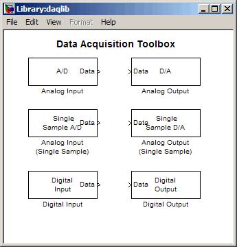
23 DAQ Programming Labview Matlab
24 DAQ Digitization Issues The big issue with digital conversion: a continuous value is made discrete In amplitude (Y axis issues) Resolution Saturation In time (X axis issues) Aliasing Leakage Frequency resolution
25 Digital DAQ SIGNAL RESOLUTION ISSUES (Y axis issues)
26 DAQ Digitization Issues Analog-Digital conversion: -quantization: -A continuous value is compared with a series of fixed, discrete intervals (states) -encoding: -The interval mean value is converted into a digital, usually binary, chain of elements
27 Digital DAQ Binary representation: Data type length = N bit Binary encoding = O / 1 Having only two states possible per element allows for very robust handling and transmission systems since the difference between states can be high and electronics is simple and cheap.
28 Digital DAQ DIGITAL RESOLUTION Having N bit data length 2 N different states 3 bit 2 3 =8 different states(1 byte = 8 bit) 8 bit 2 8 =256 states 10 bit 2 10 =1024 states 12 bit 2 12 =4096 states 14 bit 2 14 =16384 states 16 bit 2 16 =65536 states


29 output Digital DAQ AD converter transfer function is not linear: output = 2 N states input = continuous value input
30 Digital DAQ Resolution = minimum variation of the input quantity that can be detected by the AD converter. It is equal to the value of the least significant bit (the smallest one) LSB= least significant bit 1 LSB = FS / 2 N

31 Digital DAQ Resolution depends on both the full scale input of DAQ converter and bit length of data field Ex: FS=10 V N=3 bit LSB=1.25 V FS=10 V N=8 bit LSB=39 mv FS=10 V N=12 bit LSB=2.44mV resolution FS max 2 n FS min
32 DAQ Resolution Example 3-bit resolution can represent 8 voltage levels 16-bit resolution can represent 65,536 voltage levels Amplitude (volts) Bit Versus 3-Bit Resolution (5kHz Sine Wave) Time (ms) 16-bit resolution 3-bit resolution

33 DAQ Resolution Example Signal 3 bit 5 bit
34 Digital DAQ SIGNAL SAMPLING FREQUENCY ISSUES (X axis issues)
35 Digital DAQ SAMPLING: Conversion of a time continuous value into a chain of values V t V (t i, V i ) i=1,... N t
36 Digital DAQ Both V amplitude and it s time coordinates are discrete values depending on ADC capabilities and configuration SAMPLING TIME t C = t i - t i-1 SAMPLING FREQUENCY f C = 1 / t C V t i-1 t i t i+1 t
37 Digital DAQ Witch sampling frequency can be used to represent a signal without altering it? V t V t both OK, but somehow different
38 Digital DAQ If sampling frequency is too low a problem with frequency representation can occur: called aliasing V t Sampling signal is no longer recognizable, and its frequency seems lower than the original one.
39 Digital DAQ The issue of aliasing is related to the ratio between sampling frequency f S and signal frequency f A f S < 2 f A aliasing occurs f S > 2 f A f S = 2 f A f S < 2 f A
40 Digital DAQ Nyquist-Shannon theorem: if a continuous signal with a top limited bandwith contains only components with frequency up to f Amax therefore a coherent representation could be achieved bu a sampling frequency f S > 2 f Amax
41 Digital DAQ f S = 1 / t S f A = 1 / T A being f S > 2f A t S < T A / 2 We require at least two samples for each half period...
42 Nyquist Example Aliased Signal 100Hz Sine Wave Sampled at 100Hz Adequately Sampled for Frequency Only (Same # of cycles) 100Hz Sine Wave Sampled at 200Hz 100Hz Sine Wave Sampled at 1kHz Adequately Sampled for Frequency and Shape

43 DAQ Hardware 1. Signal 2. Terminal Block 3. Cable 4. DAQ Device 5. Computer 43
44 Analog to Digital Conversion (ADC) There are different methods in use that represent analog to digital conversion, such as: 1. The successive approximation ADC 2. Dual Slope Ramp ADC (long conversion time) 3. Parallel or flash A/D converter (Short conversion time).
45 ADC Successive Approximation The successive approximation ADC represents one of the (long conversion time) conversions. The Successive Approximation ADC employs a feedback system to perform the conversion. Essentially, a comparator is used to compare the input voltage, V x, to a feedback voltage, V F, that comes from a DAC. The comparator output signal drives a logic network that steps the digital output (and hence DAC input) until the comparator indicates the two signals are the same within the resolution of the converter.
46 Successive Approximation (ADC) ADC Successive Approximation
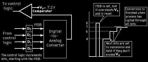


47 ADC Successive Approximation Illustration of 4-bit SAC with 1 volt step size
48 ADC Successive Approximation The logic circuitry is such that it successively sets and tests each bit, starting with the most significant bit of the word. We start with all bits zero. Thus, the first operation will be to set b 1 = 1, and test V F = V R 2-1 against V x through the comparator. If V x is greater, then b1 will be 1, b 2 is set to 1, and a test is made of V x versus V F = V R ( ), and so on. If V x is less than V R 2-1, then b 1 is reset to zero, b 2 is set to 1, and a test is made of V x versus V R 2-2. This process is repeated to the least significant bit of the word. The conversion time of successive approximation-type ADCs is on the order of 1 to 5 μs per bit.
49 ADC Successive Approximation (Example): Find the successive approximation ADC output for a 4 - bit converter to a 3.217V input if the reference is 5 V.
50 Parallel or flash ADC
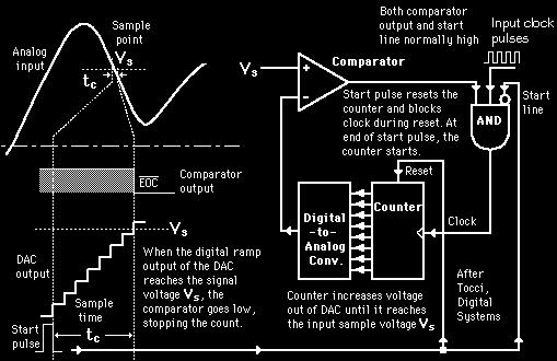
51 RAMP ADC
52 RAMP ADC The output of the DAC is applied to the other terminal of the comparator. Since the output of the DAC is increasing with the counter, it will trigger the comparator at some point when its voltage exceeds the analog input. The transition of the comparator stops the binary counter, which at that point holds the digital value corresponding to the analog voltage.
53 Digital to Analog Conversion (DAC) When data is in binary form, the 0's and 1's may be of several forms such as the TTL form where the logic zero may be a value up to 0.8 volts and the 1 may be a voltage from 2 to 5 volts. The data can be converted to clean digital form using gates which are designed to be on or off depending on the value of the incoming signal. Data in clean binary digital form can be converted to an analog form by using a summing amplifier. For example, a simple 4-bit D/A converter can be made with a four-input summing amplifier. Two Basic Approaches Weighted Summing Amplifier R-2R Network Approach
54 Weighted Sum DAC M-bit D/A converter

55 Weighted Sum DAC

56 R-2R Ladder DAC
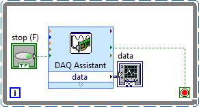
57 DAQ Example Prepare a LabVIEW code to produce and read an analog voltage using a DAQ (NI USB-6008): The Voltage output to be produced is to be output on pin (AO0). The Input Voltage to be read from pin (AI0) For the sake of simplicity, read from the input pin, the value produced from the output pin, to confirm that the produced value is the desired.

58 DAQ Example (Solution) The hardware to be used is NI USB-6008 DAQ. Connect the DAQ to the PC, and make sure its driver is installed, and running with no problems. Connect the pins to be used in this example to their target destinations (as shown below).

59 DAQ Example (Solution) Open the LabVIEW software and develop the following control front panel to be used for controlling our example. The panel shows a dial for the Analog Output to be produced, and a gauge to reflect the Analog Input sensed by the DAQ.

60 DAQ Example (Solution) In the Block Diagram, the Following code will be implemented:

61 Thank You For Your Attention! Questions?
Lab 12 Laboratory 12 Data Acquisition Required Special Equipment: 12.1 Objectives 12.2 Introduction 12.3 A/D basics
 Laboratory 12 Data Acquisition Required Special Equipment: Computer with LabView Software National Instruments USB 6009 Data Acquisition Card 12.1 Objectives This lab demonstrates the basic principals
UNIT III Data Acquisition & Microcontroller System. Mr. Manoj Rajale
 UNIT III Data Acquisition & Microcontroller System Mr. Manoj Rajale Syllabus Interfacing of Sensors / Actuators to DAQ system, Bit width, Sampling theorem, Sampling Frequency, Aliasing, Sample and hold
Data Acquisition Boards and USB-DAQ
 Data Acquisition Boards and USB-DAQ CHRISTIAN ANTFOLK Announcement Choose a project Project description deadline 26.11.2017 (you can start working on the project before that) Lab 2 will be Wednesday den
FYS3240 PC-based instrumentation and microcontrollers. Signal sampling. Spring 2017 Lecture #5
 FYS3240 PC-based instrumentation and microcontrollers Signal sampling Spring 2017 Lecture #5 Bekkeng, 30.01.2017 Content Aliasing Sampling Analog to Digital Conversion (ADC) Filtering Oversampling Triggering
FYS3240 PC-based instrumentation and microcontrollers. Signal sampling. Spring 2015 Lecture #5
 FYS3240 PC-based instrumentation and microcontrollers Signal sampling Spring 2015 Lecture #5 Bekkeng, 29.1.2015 Content Aliasing Nyquist (Sampling) ADC Filtering Oversampling Triggering Analog Signal Information
Digital to Analog Conversion. Data Acquisition
 Digital to Analog Conversion (DAC) Digital to Analog Conversion Data Acquisition DACs or D/A converters are used to convert digital signals representing binary numbers into proportional analog voltages.
A-D and D-A Converters
 Chapter 5 A-D and D-A Converters (No mathematical derivations) 04 Hours 08 Marks When digital devices are to be interfaced with analog devices (or vice a versa), Digital to Analog converter and Analog
Advantages of Analog Representation. Varies continuously, like the property being measured. Represents continuous values. See Figure 12.
 Analog Signals Signals that vary continuously throughout a defined range. Representative of many physical quantities, such as temperature and velocity. Usually a voltage or current level. Digital Signals
Analog to Digital Conversion
 Analog to Digital Conversion 02534567998 6 4 2 3 4 5 6 ANALOG to DIGITAL CONVERSION Analog variation (Continuous, smooth variation) Digitized Variation (Discrete set of points) N2 N1 Digitization applied
Analog to Digital Converters
 Analog to Digital Converters By: Byron Johns, Danny Carpenter Stephanie Pohl, Harry Bo Marr http://ume.gatech.edu/mechatronics_course/fadc_f05.ppt (unless otherwise marked) Presentation Outline Introduction:
Data acquisition and instrumentation. Data acquisition
 Data acquisition and instrumentation START Lecture Sam Sadeghi Data acquisition 1 Humanistic Intelligence Body as a transducer,, data acquisition and signal processing machine Analysis of physiological
ANALOG TO DIGITAL (ADC) and DIGITAL TO ANALOG CONVERTERS (DAC)
 and DIGITAL TO ANALOG CONVERTERS (DAC)") COURSE / CODE DIGITAL SYSTEM FUNDAMENTALS (ECE421) DIGITAL ELECTRONICS FUNDAMENTAL (ECE422) ANALOG TO DIGITAL (ADC) and DIGITAL TO ANALOG CONVERTERS (DAC) Connecting digital circuitry to sensor devices
COURSE / CODE DIGITAL SYSTEM FUNDAMENTALS (ECE421) DIGITAL ELECTRONICS FUNDAMENTAL (ECE422) ANALOG TO DIGITAL (ADC) and DIGITAL TO ANALOG CONVERTERS (DAC) Connecting digital circuitry to sensor devices
Advanced Lab LAB 6: Signal Acquisition & Spectrum Analysis Using VirtualBench DSA Equipment: Objectives:
 Advanced Lab LAB 6: Signal Acquisition & Spectrum Analysis Using VirtualBench DSA Equipment: Pentium PC with National Instruments PCI-MIO-16E-4 data-acquisition board (12-bit resolution; software-controlled
ELG3336 Design of Mechatronics System
 ELG3336 Design of Mechatronics System Elements of a Data Acquisition System 2 Analog Signal Data Acquisition Hardware Your Signal Data Acquisition DAQ Device System Computer Cable Terminal Block Data Acquisition
PHYS225 Lecture 22. Electronic Circuits
 PHYS225 Lecture 22 Electronic Circuits Last lecture Digital to Analog Conversion DAC Converts digital signal to an analog signal Computer control of everything! Various types/techniques for conversion
Analog to digital and digital to analog converters
 Analog to digital and digital to analog converters A/D converter D/A converter ADC DAC ad da Number bases Decimal, base, numbers - 9 Binary, base, numbers and Oktal, base 8, numbers - 7 Hexadecimal, base
P a g e 1. Introduction
 P a g e 1 Introduction 1. Signals in digital form are more convenient than analog form for processing and control operation. 2. Real world signals originated from temperature, pressure, flow rate, force
Chapter 7. Introduction. Analog Signal and Discrete Time Series. Sampling, Digital Devices, and Data Acquisition
 Chapter 7 Sampling, Digital Devices, and Data Acquisition Material from Theory and Design for Mechanical Measurements; Figliola, Third Edition Introduction Integrating analog electrical transducers with
ni.com Sensor Measurement Fundamentals Series
 Sensor Measurement Fundamentals Series Introduction to Data Acquisition Basics and Terminology Litkei Márton District Sales Manager National Instruments What Is Data Acquisition (DAQ)? 3 Why Measure? Engineers
CHAPTER ELEVEN - Interfacing With the Analog World
 CHAPTER ELEVEN - Interfacing With the Analog World 11.1 (a) Analog output = (K) x (digital input) (b) Smallest change that can occur in the analog output as a result of a change in the digital input. (c)
NI DAQPad -6020E Family Specifications
 NI DAQPad -6020E Family Specifications This document lists the I/O terminal summary and specifications for the NI DAQPad-6020E family of devices. This family includes the following devices: NI DAQPad-6020E
LAB #7: Digital Signal Processing
 LAB #7: Digital Signal Processing Equipment: Pentium PC with NI PCI-MIO-16E-4 data-acquisition board NI BNC 2120 Accessory Box VirtualBench Instrument Library version 2.6 Function Generator (Tektronix
Version Futek Instruments, LLC
 FT_ez_DAQ User s Manual Version 2.0.0 Futek Instruments, LLC Table of Contents 1. Introduction... 3 2. System Requirements... 3 3. Software Installation... 4 3.1 Application software and USB driver installation...
Analog-to-Digital Converter (ADC) And Digital-to-Analog Converter (DAC)
 And Digital-to-Analog Converter (DAC)") 1 Analog-to-Digital Converter (ADC) And Digital-to-Analog Converter (DAC) 2 1. DAC In an electronic circuit, a combination of high voltage (+5V) and low voltage (0V) is usually used to represent a binary
1 Analog-to-Digital Converter (ADC) And Digital-to-Analog Converter (DAC) 2 1. DAC In an electronic circuit, a combination of high voltage (+5V) and low voltage (0V) is usually used to represent a binary
USB Multifunction Arbitrary Waveform Generator AWG2300. User Guide
 USB Multifunction Arbitrary Waveform Generator AWG2300 User Guide Contents Safety information... 3 About this guide... 4 AWG2300 specifications... 5 Chapter 1. Product introduction 1 1. Package contents......
Multiple Instrument Station Module
 Multiple Instrument Station Module Digital Storage Oscilloscope Vertical Channels Sampling rate Bandwidth Coupling Input impedance Vertical sensitivity Vertical resolution Max. input voltage Horizontal
Analog I/O. ECE 153B Sensor & Peripheral Interface Design Winter 2016
 Analog I/O ECE 153B Sensor & Peripheral Interface Design Introduction Anytime we need to monitor or control analog signals with a digital system, we require analogto-digital (ADC) and digital-to-analog
NI 6013/6014 Family Specifications
 NI 6013/6014 Family Specifications This document lists the I/O terminal summary and specifications for the NI 6013/6014 family of devices. This family includes the following devices: NI PCI-6013 NI PCI-6014
USB-TEMP and TC Series USB-Based Temperature Measurement Devices
 USB-Based Temperature Measurement Devices Features Temperature and voltage measurement USB devices Thermocouple, RTD, thermistor, or semiconductor sensor measurements Eight analog inputs Up to ±10 V inputs*
Measuring Voltage and Time Quantities of a Signal Through a Virtual Oscilloscope
 AASCIT Journal of Physics 2017; 3(2): 5-12 http://www.aascit.org/journal/physics ISSN: 2381-1358 (Print); ISSN: 2381-1366 (Online) Measuring Voltage and Time Quantities of a Signal Through a G. Tektas
University of Pennsylvania. Department of Electrical and Systems Engineering. ESE Undergraduate Laboratory. Analog to Digital Converter
 University of Pennsylvania Department of Electrical and Systems Engineering ESE Undergraduate Laboratory Analog to Digital Converter PURPOSE The purpose of this lab is to design and build a simple Digital-to-Analog
ET 438B Sequential Digital Control and Data Acquisition Laboratory 4 Analog Measurement and Digital Control Integration Using LabVIEW
 ET 438B Sequential Digital Control and Data Acquisition Laboratory 4 Analog Measurement and Digital Control Integration Using LabVIEW Laboratory Learning Objectives 1. Identify the data acquisition card
Data Converters. Dr.Trushit Upadhyaya EC Department, CSPIT, CHARUSAT
 Data Converters Dr.Trushit Upadhyaya EC Department, CSPIT, CHARUSAT Purpose To convert digital values to analog voltages V OUT Digital Value Reference Voltage Digital Value DAC Analog Voltage Analog Quantity:
EKT 314/4 LABORATORIES SHEET
 EKT 314/4 LABORATORIES SHEET WEEK DAY HOUR 4 1 2 PREPARED BY: EN. MUHAMAD ASMI BIN ROMLI EN. MOHD FISOL BIN OSMAN JULY 2009 Creating a Typical Measurement Application 5 This chapter introduces you to common
Auntie Spark s Guide to creating a Data Collection VI
 Auntie Spark s Guide to creating a Data Collection VI Suppose you wanted to gather data from an experiment. How would you create a VI to do so? For sophisticated data collection and experimental control,
Considerations for Analog Input and Output
 Considerations for Analog Input and Output Useful information can be found in the text in Sections 6.7.1 (Data Rates), 6.7.5 (Analog Input Signals), 6.7.6 (Multiple Signal Sources: Data Loggers), 6.7.9
CHAPTER 10: DIGITAL INSTRUMENTATION PRINCIPLES
 I. Why digital? CHAPTER 10: DIGITAL INSTRUMENTATION PRINCIPLES Almost all the transducers we have considered so far have had an analog output, that is, the output is a different form from the input but
DT 9818 Waveform-Generator. Hardware Trigger Version. Operating Manual. Version 2.0. May Page 1 of 21
 DT 9818 Waveform-Generator Hardware Trigger Version Operating Manual Version 2.0 May 2011 Page 1 of 21 Table of Contents 1 Components... 3 1.1 USB DAQ module DT 9818-16SE-BNC... 3 1.2 DT 9818 Waveform-Generator-CD...
Data Acquisition: A/D & D/A Conversion
 Data Acquisition: A/D & D/A Conversion Mark Colton ME 363 Spring 2011 Sampling: A Review In order to store and process measured variables in a computer, the computer must sample the variables 10 Continuous
EEE312: Electrical measurement & instrumentation
 University of Turkish Aeronautical Association Faculty of Engineering EEE department EEE312: Electrical measurement & instrumentation Digital Electronic meters BY Ankara March 2017 1 Introduction The digital
DT9838. Strain- and Bridge-Based Measurement Module. Key Features: Bridge Configurations. Analog Input Features
 Strain- and Bridge-Based Measurement Module The module is a strain gage measurement device intended for full-, half, and quarter-bridge strain gage elements and bridge-based sensor assemblies such as load
DSP Project. Reminder: Project proposal is due Friday, October 19, 2012 by 5pm in my office (Small 239).
.") DSP Project eminder: Project proposal is due Friday, October 19, 2012 by 5pm in my office (Small 239). Budget: $150 for project. Free parts: Surplus parts from previous year s project are available on
DSP Project eminder: Project proposal is due Friday, October 19, 2012 by 5pm in my office (Small 239). Budget: $150 for project. Free parts: Surplus parts from previous year s project are available on
Graphical Control Panel User Manual
 Graphical Control Panel User Manual DS-MPE-DAQ0804 PCIe Minicard Data Acquisition Module For Universal Driver Version 7.0.0 and later Revision A.0 March 2015 Revision Date Comment A.0 3/18/2015 Initial
MECE 3320 Measurements & Instrumentation. Data Acquisition
 MECE 3320 Measurements & Instrumentation Data Acquisition Dr. Isaac Choutapalli Department of Mechanical Engineering University of Texas Pan American Sampling Concepts 1 f s t Sampling Rate f s 2 f m or
INTEGRATED CIRCUITS. AN109 Microprocessor-compatible DACs Dec
 INTEGRATED CIRCUITS 1988 Dec DAC products are designed to convert a digital code to an analog signal. Since a common source of digital signals is the data bus of a microprocessor, DAC circuits that are
ADS9850 Signal Generator Module
 1. Introduction ADS9850 Signal Generator Module This module described here is based on ADS9850, a CMOS, 125MHz, and Complete DDS Synthesizer. The AD9850 is a highly integrated device that uses advanced
Specifications. PCI Bus. Analog Input Input Characteristics
 Specifications A This appendix lists the specifications of the NI 6034E/6035E/6036E. These specifications are typical at 25 C unless otherwise noted. The first section provides the specifications for the
Page 1/10 Digilent Analog Discovery (DAD) Tutorial 6-Aug-15. Figure 2: DAD pin configuration
 Tutorial 6-Aug-15. Figure 2: DAD pin configuration") Page 1/10 Digilent Analog Discovery (DAD) Tutorial 6-Aug-15 INTRODUCTION The Diligent Analog Discovery (DAD) allows you to design and test both analog and digital circuits. It can produce, measure and
Page 1/10 Digilent Analog Discovery (DAD) Tutorial 6-Aug-15 INTRODUCTION The Diligent Analog Discovery (DAD) allows you to design and test both analog and digital circuits. It can produce, measure and
USB4. Encoder Data Acquisition USB Device Page 1 of 8. Description. Features
 USB4 Page 1 of 8 The USB4 is a data acquisition device designed to record data from 4 incremental encoders, 8 digital inputs and 4 analog input channels. In addition, the USB4 provides 8 digital outputs
Laboratory Experiment #1 Introduction to Spectral Analysis
 J.B.Francis College of Engineering Mechanical Engineering Department 22-403 Laboratory Experiment #1 Introduction to Spectral Analysis Introduction The quantification of electrical energy can be accomplished
Fundamentals of Data Converters. DAVID KRESS Director of Technical Marketing
 Fundamentals of Data Converters DAVID KRESS Director of Technical Marketing 9/14/2016 Analog to Electronic Signal Processing Sensor (INPUT) Amp Converter Digital Processor Actuator (OUTPUT) Amp Converter
NI 6731/6733 Specifications
 NI 6731/6733 Specifications This document lists the specifications for the NI 6731/6733 analog output devices. The following specifications are typical at 25 C unless otherwise noted. Note With NI-DAQmx,
EKT 314/4 LABORATORIES SHEET
 EKT 314/4 LABORATORIES SHEET WEEK DAY HOUR 4 2 1 PREPARED BY: EN. MUHAMAD ASMI BIN ROMLI EN. MOHD FISOL BIN OSMAN JULY 2009 Measuring Strain 10 This chapter describes how to measure strain using DAQ devices
NI 6143 Specifications
 NI 6143 Specifications This document lists the I/O terminal summary and specifications for the NI PCI/PXI-6143. For the most current edition of this document, refer to ni.com/manuals. Refer to the DAQ
ELG4139: Converters Analog to Digital Converters (ADCs) Digital to Analog Converters (DACs)
 Digital to Analog Converters (DACs)") ELG4139: Converters Analog to Digital Converters (ADCs) Digital to Analog Converters (DACs) Digital Output Dout 111 110 101 100 011 010 001 000 ΔV, V LSB V ref 8 V FS 4 V 8 ref 7 V 8 ref Analog Input V
ELG4139: Converters Analog to Digital Converters (ADCs) Digital to Analog Converters (DACs) Digital Output Dout 111 110 101 100 011 010 001 000 ΔV, V LSB V ref 8 V FS 4 V 8 ref 7 V 8 ref Analog Input V
APPLICATION BULLETIN PRINCIPLES OF DATA ACQUISITION AND CONVERSION. Reconstructed Wave Form
 APPLICATION BULLETIN Mailing Address: PO Box 11400 Tucson, AZ 85734 Street Address: 6730 S. Tucson Blvd. Tucson, AZ 85706 Tel: (60) 746-1111 Twx: 910-95-111 Telex: 066-6491 FAX (60) 889-1510 Immediate
Chapter 2 Signal Conditioning, Propagation, and Conversion
 09/0 PHY 4330 Instrumentation I Chapter Signal Conditioning, Propagation, and Conversion. Amplification (Review of Op-amps) Reference: D. A. Bell, Operational Amplifiers Applications, Troubleshooting,
QUICK START GUIDE FOR DEMONSTRATION CIRCUIT BIT, 250KSPS ADC
 DESCRIPTION QUICK START GUIDE FOR DEMONSTRATION CIRCUIT 1255 LTC1605CG/LTC1606CG The LTC1606 is a 250Ksps ADC that draws only 75mW from a single +5V Supply, while the LTC1605 is a 100Ksps ADC that draws
UNIVERSITY of PENNSYLVANIA DEPARTMENT OF ELECTRICAL AND SYSTEMS ENGINEERING ESE Undergraduate Labs Electrical Circuits and Systems II Laboratory
 UNIVERSITY of PENNSYLVANIA DEPARTMENT OF ELECTRICAL AND SYSTEMS ENGINEERING ESE Undergraduate Labs Electrical Circuits and Systems II Laboratory Overview Analog-to-Digital (ADC) and Digital-to-Analog (DAC)
Laboratory Assignment 1 Sampling Phenomena
 1 Main Topics Signal Acquisition Audio Processing Aliasing, Anti-Aliasing Filters Laboratory Assignment 1 Sampling Phenomena 2.171 Analysis and Design of Digital Control Systems Digital Filter Design and
Electronics II Physics 3620 / 6620
 Electronics II Physics 3620 / 6620 Feb 09, 2009 Part 1 Analog-to-Digital Converters (ADC) 2/8/2009 1 Why ADC? Digital Signal Processing is more popular Easy to implement, modify, Low cost Data from real
SU QuarkNet Workshop 2012 Lab Activity 5 ELECTRONICS II: ADCs & DAQ
 SU Lab Activity 5 ELECTRONICS II: ADCs & DAQ Laboratory Goals 1. Learn about data conversion (analog to digital, ADC). 2. Understand how an ADC works, measure the calibration curve, and determine the frequency
Module 1: Introduction to Experimental Techniques Lecture 2: Sources of error. The Lecture Contains: Sources of Error in Measurement
 The Lecture Contains: Sources of Error in Measurement Signal-To-Noise Ratio Analog-to-Digital Conversion of Measurement Data A/D Conversion Digitalization Errors due to A/D Conversion file:///g /optical_measurement/lecture2/2_1.htm[5/7/2012
DT9838 Strain Measurement Module
 Strain- and Bridge-Based Measurement Module Strain Measurement Module The module is a strain gage measurement device intended for full-, half, and quarter-bridge strain gage elements and bridge-based sensor
Chapter 2 Analog-to-Digital Conversion...
 Chapter... 5 This chapter examines general considerations for analog-to-digital converter (ADC) measurements. Discussed are the four basic ADC types, providing a general description of each while comparing
Lab 2A: Introduction to Sensing and Data Acquisition
 Lab 2A: Introduction to Sensing and Data Acquisition Prof. R.G. Longoria Department of Mechanical Engineering The University of Texas at Austin June 12, 2014 1 Lab 2A 2 Sensors 3 DAQ 4 Experimentation
Ch 5 Hardware Components for Automation
 Ch 5 Hardware Components for Automation Sections: 1. Sensors 2. Actuators 3. Analog-to-Digital Conversion 4. Digital-to-Analog Conversion 5. Input/Output Devices for Discrete Data Computer-Process Interface
ELG3336: Converters Analog to Digital Converters (ADCs) Digital to Analog Converters (DACs)
 Digital to Analog Converters (DACs)") ELG3336: Converters Analog to Digital Converters (ADCs) Digital to Analog Converters (DACs) Digital Output Dout 111 110 101 100 011 010 001 000 ΔV, V LSB V ref 8 V FSR 4 V 8 ref 7 V 8 ref Analog Input
ELG3336: Converters Analog to Digital Converters (ADCs) Digital to Analog Converters (DACs) Digital Output Dout 111 110 101 100 011 010 001 000 ΔV, V LSB V ref 8 V FSR 4 V 8 ref 7 V 8 ref Analog Input
Digital Sampling. This Lecture. Engr325 Instrumentation. Dr Curtis Nelson. Digital sampling Sample rate. Bit depth. Other terms. Types of conversion.
 Digital Sampling Engr325 Instrumentation Dr Curtis Nelson Digital sampling Sample rate. Bit depth. Other terms. Types of conversion. This Lecture 1 Data Acquisition and Control Computers are nearly always
University of California at Berkeley Donald A. Glaser Physics 111A Instrumentation Laboratory
 Published on Instrumentation LAB (http://instrumentationlab.berkeley.edu) Home > Lab Assignments > Digital Labs > Digital Circuits II Digital Circuits II Submitted by Nate.Physics on Tue, 07/08/2014-13:57
DAC A (VCO) Buffer (write) DAC B (AGC) Buffer (write) Pulse Code Buffer (write) Parameter Buffer (write) Figure A.1. Receiver Controller Registers
 Buffer (write) DAC B (AGC) Buffer (write) Pulse Code Buffer (write) Parameter Buffer (write) Figure A.1. Receiver Controller Registers") Appendix A. Host Computer Interface The host computer interface is contained on a plug-in module designed for the IBM PC/XT/AT bus. It includes the converters, counters, registers and programmed-logic
Appendix A. Host Computer Interface The host computer interface is contained on a plug-in module designed for the IBM PC/XT/AT bus. It includes the converters, counters, registers and programmed-logic
CHAPTER 7 HARDWARE IMPLEMENTATION
 168 CHAPTER 7 HARDWARE IMPLEMENTATION 7.1 OVERVIEW In the previous chapters discussed about the design and simulation of Discrete controller for ZVS Buck, Interleaved Boost, Buck-Boost, Double Frequency
Analyzing A/D and D/A converters
 Analyzing A/D and D/A converters 2013. 10. 21. Pálfi Vilmos 1 Contents 1 Signals 3 1.1 Periodic signals 3 1.2 Sampling 4 1.2.1 Discrete Fourier transform... 4 1.2.2 Spectrum of sampled signals... 5 1.2.3
Introduction to NI LabVIEW and Computer-Based Measurements. Elias Nicolas Applications Engineer National Instruments
 Introduction to NI LabVIEW and Computer-Based Measurements Elias Nicolas Applications Engineer National Instruments Today, We ll Explore: The Challenges of Making Measurements Introduction to LabVIEW Fundamentals
DI-1100 USB Data Acquisition (DAQ) System Communication Protocol
 System Communication Protocol") DI-1100 USB Data Acquisition (DAQ) System Communication Protocol DATAQ Instruments Although DATAQ Instruments provides ready-to-run WinDaq software with its DI-1100 Data Acquisition Starter Kits, programmers
DI-1100 USB Data Acquisition (DAQ) System Communication Protocol DATAQ Instruments Although DATAQ Instruments provides ready-to-run WinDaq software with its DI-1100 Data Acquisition Starter Kits, programmers
 Switch/ Jumper Table 1-1: Factory Settings Factory Settings (Jumpers Installed) Function Controlled Activates pull-up/ pull-down resistors on Port 0 digital P7 I/O lines Activates pull-up/ pull-down resistors
Introduction. These two operations are performed by data converters : Analogue-to-digital converter (ADC) Digital-to-analogue converter (DAC)
 Digital-to-analogue converter (DAC)") Lezione 7 Conversione analogico digitale Introduzione Campionamento di segnali analogici e Aliasing Porte di campionamento e di mantenimento Quantizzazione segnali analogici Ricostruzione del segnale analogico
Lezione 7 Conversione analogico digitale Introduzione Campionamento di segnali analogici e Aliasing Porte di campionamento e di mantenimento Quantizzazione segnali analogici Ricostruzione del segnale analogico
Ethernet-Based Temperature, Voltage and Strain Measurement Modules
 Ethernet-Based Temperature, Voltage and Strain Measurement Modules OMB-NET6000 Series OMB-NET6220 shown smaller than actual size. U 12 Analog Inputs U 8 Digital I/O U Simultaneous Sampling U Multiple Trigger
8-Bit, high-speed, µp-compatible A/D converter with track/hold function ADC0820
 8-Bit, high-speed, µp-compatible A/D converter with DESCRIPTION By using a half-flash conversion technique, the 8-bit CMOS A/D offers a 1.5µs conversion time while dissipating a maximum 75mW of power.
Data Acquisition & Computer Control
 Chapter 4 Data Acquisition & Computer Control Now that we have some tools to look at random data we need to understand the fundamental methods employed to acquire data and control experiments. The personal
1. R-2R ladder Digital-Analog Converters (DAC). Connect the DAC boards (2 channels) and Nexys 4 board according to Fig. 1.
. Connect the DAC boards (2 channels) and Nexys 4 board according to Fig. 1.") Analog-Digital and Digital-Analog Converters Digital Electronics Labolatory Ernest Jamro, Maciej Wielgosz, Piotr Rzeszut Dep. of Electronics, AGH-UST, Kraków Poland, 2015-01-10 1. R-2R ladder Digital-Analog
Analog-Digital and Digital-Analog Converters Digital Electronics Labolatory Ernest Jamro, Maciej Wielgosz, Piotr Rzeszut Dep. of Electronics, AGH-UST, Kraków Poland, 2015-01-10 1. R-2R ladder Digital-Analog
EE 421L Digital Electronics Laboratory. Laboratory Exercise #9 ADC and DAC
 EE 421L Digital Electronics Laboratory Laboratory Exercise #9 ADC and DAC Department of Electrical and Computer Engineering University of Nevada, at Las Vegas Objective: The purpose of this laboratory
System on a Chip. Prof. Dr. Michael Kraft
 System on a Chip Prof. Dr. Michael Kraft Lecture 5: Data Conversion ADC Background/Theory Examples Background Physical systems are typically analogue To apply digital signal processing, the analogue signal
Electronics A/D and D/A converters
 Electronics A/D and D/A converters Prof. Márta Rencz, Gábor Takács, Dr. György Bognár, Dr. Péter G. Szabó BME DED December 1, 2014 1 / 26 Introduction The world is analog, signal processing nowadays is
Based with permission on lectures by John Getty Laboratory Electronics II (PHSX262) Spring 2011 Lecture 9 Page 1
 Spring 2011 Lecture 9 Page 1") Today 3// Lecture 9 Analog Digital Conversion Sampled Data Acquisition Systems Discrete Sampling and Nyquist Digital to Analog Conversion Analog to Digital Conversion Homework Study for Exam next week
Today 3// Lecture 9 Analog Digital Conversion Sampled Data Acquisition Systems Discrete Sampling and Nyquist Digital to Analog Conversion Analog to Digital Conversion Homework Study for Exam next week
Exercise 3: Sound volume robot
 ETH Course 40-048-00L: Electronics for Physicists II (Digital) 1: Setup uc tools, introduction : Solder SMD Arduino Nano board 3: Build application around ATmega38P 4: Design your own PCB schematic 5:
Computerized Data Acquisition Systems. Chapter 4
 Computerized Data Acquisition Systems Chapter 4 Data Acquisition - Objectives State and discuss in terms a bright high school student would understand the following definitions related to data acquisition
Digital Design Laboratory Lecture 7. A/D and D/A
 ECE 280 / CSE 280 Digital Design Laboratory Lecture 7 A/D and D/A Analog/Digital Conversion A/D conversion is the process of sampling a continuous signal Two significant implications 1. The information
PC-OSCILLOSCOPE PCS500. Analog and digital circuit sections. Description of the operation
 PC-OSCILLOSCOPE PCS500 Analog and digital circuit sections Description of the operation Operation of the analog section This description concerns only channel 1 (CH1) input stages. The operation of CH2
LLRF4 Evaluation Board
 LLRF4 Evaluation Board USPAS Lab Reference Author: Dmitry Teytelman Revision: 1.1 June 11, 2009 Copyright Dimtel, Inc., 2009. All rights reserved. Dimtel, Inc. 2059 Camden Avenue, Suite 136 San Jose, CA
4 x 10 bit Free Run A/D 4 x Hi Comparator 4 x Low Comparator IRQ on Compare MX839. C-BUS Interface & Control Logic
 DATA BULLETIN MX839 Digitally Controlled Analog I/O Processor PRELIMINARY INFORMATION Features x 4 input intelligent 10 bit A/D monitoring subsystem 4 High and 4 Low Comparators External IRQ Generator
Real Time Embedded Systems. Lecture 1 January 17, 2012
 Analog Real Time Embedded Systems www.atomicrhubarb.com/embedded Lecture 1 January 17, 2012 Topic Section Topic Where in the books Catsoulis chapter/page Simon chapter/page Zilog UM197 (ZNEO Z16F Series
ANALOG TO DIGITAL CONVERTER ANALOG INPUT
 ANALOG INPUT Analog input involves sensing an electrical signal from some source external to the computer. This signal is generated as a result of some changing physical phenomenon such as air pressure,
Design Implementation Description for the Digital Frequency Oscillator
 Appendix A Design Implementation Description for the Frequency Oscillator A.1 Input Front End The input data front end accepts either analog single ended or differential inputs (figure A-1). The input
II Year (04 Semester) EE6403 Discrete Time Systems and Signal Processing
 EE6403 Discrete Time Systems and Signal Processing") Class Subject Code Subject II Year (04 Semester) EE6403 Discrete Time Systems and Signal Processing 1.CONTENT LIST: Introduction to Unit I - Signals and Systems 2. SKILLS ADDRESSED: Listening 3. OBJECTIVE
Class Subject Code Subject II Year (04 Semester) EE6403 Discrete Time Systems and Signal Processing 1.CONTENT LIST: Introduction to Unit I - Signals and Systems 2. SKILLS ADDRESSED: Listening 3. OBJECTIVE
Chapter 5: Signal conversion
 Chapter 5: Signal conversion Learning Objectives: At the end of this topic you will be able to: explain the need for signal conversion between analogue and digital form in communications and microprocessors
AWG414 4-GSPS 12-bit Dual-Channel Arbitrary Waveform Generator
 AWG414 4-GSPS 12-bit Dual-Channel Arbitrary Waveform Generator PRODUCT DESCRIPTION The AWG414 modules generate dual channel arbitrary CW waveforms with sampling rates up to 4 GSPS. The on-board SRAMs provide
NI 6023E/6024E/6025E Family Specifications
 NI 6023E/6024E/6025E Family Specifications This document lists the I/O terminal summary and specifications for the devices that make up the NI 6023E/6024E/6025E family of devices. This family includes
Analog-Digital Interface
 Analog-Digital Interface Tuesday 24 November 15 Summary Previous Class Dependability Today: Redundancy Error Correcting Codes Analog-Digital Interface Converters, Sensors / Actuators Sampling DSP Frequency
WaveStation Function/Arbitrary Waveform Generators
 WaveStation Function/Arbitrary Waveform Generators Key Features High performance with 14-bit, 125 MS/s and 16 kpts 2 channels on all models Large 3.5 color display for easy waveform preview Over 40 built-in