COLLEGE COLLEGE OF ENGINEERING & COMPUTER SCIENCE ASSOCIATE DEAN: DR. MOHAMMAD ILYAS GEOMATIC ENGINEERING PROGRAM
|
|
|
- Madeleine Gilmore
- 5 years ago
- Views:
Transcription


1 COLLEGE COLLEGE OF ENGINEERING & COMPUTER SCIENCE DEAN: DR. KARL STEVENS ASSOCIATE DEAN: DR. MOHAMMAD ILYAS GEOMATIC ENGINEERING PROGRAM INTERIM PROGRAM DIRECTOR: DR. DON LEONE P.E. STAFF & FUTURE ENGINEERS, SURVEYORS, ARCHITECTS & SCIENTISTS Nov. 13 th,
 and modern geophysical imaging")

2 SUE, RT and Geomatics How do Subsurface Utility Engineering (SUE) and modern geophysical imaging techniques es such as Radar Tomography (RT) relate to Geomatics? Ralf Birken, Ph.D. Chief Scientist Nov. 13 th,
3 O U T L I N E Introduction Subsurface Utility Engineering i (SUE) and established Geophysics Modern Array-based Land-based Geophysical Methods Radar Tomography Concepts, Systems and Methodology, and Case Histories Electromagnetic Induction Arrays Concepts, Systems and Methodology, and Case Histories SUE and the Impact of Geophysical Arrays Legislation and Certification Summary Nov. 13 th,
4 Introduction Geomatics Engineering is a modern discipline, i which h integrates t acquisition, iti modeling, analysis, and management of spatially referenced data, i.e. data identified according to their locations. Based on the scientific framework of geodesy, it uses terrestrial, t marine, airborne, and satellite-based sensors to acquire spatial and other data. It includes the process of transforming spatially referenced data from different sources it into common information if systems with well-defined accuracy characteristics." Subsurface Geomatics? How do you acquire accurate surveying data of subsurface features? What accuracies can you expect? ww.geomatics.ucalg gary.ca/about/wha tis Nov. 13 th,
5 Subsurface Utility Engineering (SUE) and established Geophysics Greg Jeffries Vice President Nov. 13 th,

: Information obtained by surveying and")

6 SUE and established Geophysics Quality Level D (QL D): If Information derived d from existing iti records or oral recollections. Quality Level C (QL C): Information obtained by surveying and plotting visible above-ground utility features and by using professional judgment in correlating this information to QL D information. Based on CI/ASCE standards d and summary by Anspach Nov. 13 th,
7 SUE and established Geophysics Quality Level B (QL B): Information obtained through h the application of appropriate surface geophysical methods to determine the existence and approximate horizontal position of subsurface utilities. QL B data should be reproducible by surface geophysics at any point of their depiction. This information is surveyed to applicable tolerances defined by the project and reduced onto plan documents. Based on CI/ASCE standards d and summary by Anspach Nov. 13 th,
8 SUE and established Geophysics Quality Level A (QL A): Precise horizontal and vertical location of utilities obtained by the actual exposure (or verification of previously exposed and surveyed utilities) and subsequent measurement of subsurface utilities, usually at a specific point. Minimally intrusive excavation equipment is typically used to minimize the potential for utility damage. A precise horizontal and vertical location as well as other utility attributes is shown on plan documents. Accuracy is typically set at 15mm vertical, and to applicable horizontal survey and mapping. Based on CI/ASCE standards and summary by Anspach Nov. 13 th,


9 SUE and established Geophysics Commonly used geophysical methods: Pipe and cable locators Terrain conductivity meters Metal detectors Ground Penetrating Radar (GPR) Magnetic methods Acoustic Methods Optical systems Nov. 13 th,
10 SUE and established Geophysics Common features: Typically handheld or pushcart-based single channel systems Typically no geo-referenced data recording Sparse non-continuous coverage Big gap between QL B and QL A as far as: Cost Accuracy (Horizontal and Vertical) Both lack continuous Coverage Nov. 13 th,
11 SUE and established Geophysics Suggestion to narrow gap between QL B and QL A using: Array-based Surface Geophysical Methods As far as: Continuous Coverage Horizontal and Vertical Position Cost versus Risk Reusable georeferenced digital data Higher COST Lower QL A SUE Quality Levels QL B QL C QL D RISK Higher ih Nov. 13 th,
12 References American Society of Civil Engineers (2002). C/I ASCE 38-02, Standard d Guideline for the Collection and Depiction of Existing Subsurface Utility Data. Reston, VA. Anspach, J.H., 2002 (?), Underground d utility security issues at critical facilities:?, 5 pages. Nov. 13 th,
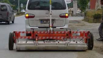
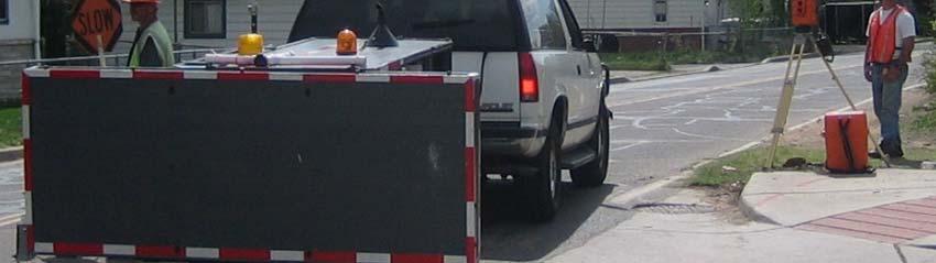
13 Modern Array-based Land-based Geophysical Methods Multi-channel geophysical systems Deployed through vehicle (some even within traffic flow) Movement tracked through survey-grade positioning system Create accurate geo-referenced digital data sets Able to cover large areas efficiently with dense continuous data coverage Allow more advanced methods of data interpretation Option to combine multiple arrays in single data collection effort Surveyor certified accuracy and final maps Nov. 13 th,
14 Radar Tomography y( (RT) Concept Nov. 13 th,


 ti")


15 Common 2D GPR Survey Grids 2 feet or more between profiles 4 inches or more between ti triggers (stations) ti Rarely uses accurate geometry control, regarding line spacing and direction Nov. 13 th,


16 GPR Section with Point Reflectors GPR is also looking to the side T R T R T R T R T R T R T R T R T Note: Point reflectors and pipes perpendicular to the profile appear the same in 2D GPR section Nov. 13 th,


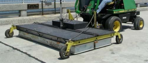
17 Array GPR Advantages - I Efficiency in data collection, especially when survey area large (>40, sqft) and target small requiring small profile spacing Standard GPR System 1 Tx Rx channel Array GPR System 16 Tx Rx channels 12.5 cm swath of coverage in one profile Transmitting antenna (Tx) 2.0 m swath of coverage in one profile Receiving antenna (Rx) Nov. 13 th,
18 Array GPR Advantages - II A dense grid of multiple 2D GPR profiles allows synthetic aperture focusing to create a stack of image slices at different depths to create a 3D image below ground. Dense 2D grid becomes 3D GPR grid when profile spacing close to station spacing Depth Goal: One GPR trace every 5 inches or less in in-line and cross-profile direction Nov. 13 th,
19 Radar Tomography y( (RT) Systems and Methodology Nov. 13 th,
 Joint development of Witten")

20 Radar Tomography (Ground-Penetrating Imaging Radar) Joint development of Witten Technologies Inc., Malå Geoscience, ConEdison Schlumberger, EPRI, GTI (formerly GRI) Nov. 13 th,
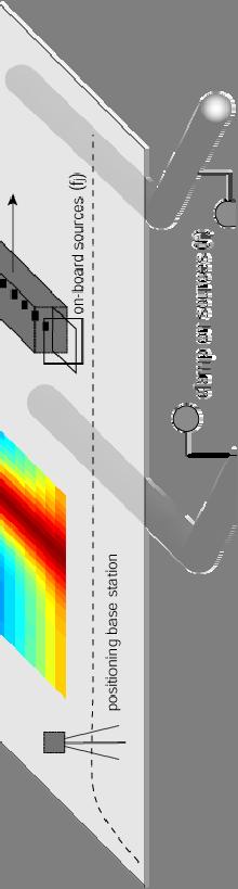
21 Radar Tomography (RT) RT: A GPR survey or system that combines efficient radar surveying with precise positioning control and advanced signal processing allowing the creation of high-resolution 3D radar images of the subsurface on a large-scale. Meaning: precise positioning = centimeters large-scale scale = surveys covering thousands of square meters high-resolution = resolution of centimeters Nov. 13 th,


22 Radar Tomography (RT) Methodology Rd Radar Arrays Survey-grade Positioning prism Continues 3D Radar Images Accurate Certified Utility Maps laser theodolite Nov. 13 th,
23 Please wait for movie to start Jax_Region_09_with_pictometry_tweak-2.mov ith i t t t Nov. 13 th,


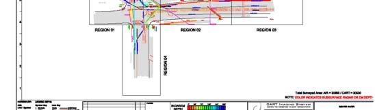
24 CART Imaging gsystem Computer Assisted Radar Tomography Total daily coverage: 40,000 80,000 sqft Spatial resolution (16 channel mode): ~ 5 channel or cross-line spacing ~ 4 trace or in-line spacing Maximum Driving i Speed: 5 mi/hr Radar component of CART Imaging System is manufactured by Malå Geoscience Nov. 13 th,


25 CART Schematic 400 and 200 MHz antennas Nov. 13 th,
26 Operational Specifications in Words Depth of penetration is 4 to 6 ft in most sandy-clay soils (8 to 12 ft in sandy soils), very site specific, conservative Depth accuracy is about 5% (i.e., ± 3 in. over 5 ft) Horizontal accuracy is about 1% from mapped surface features such as manhole covers or curb lines Resolution of subsurface objects is about 3 to 4 in. Objects as small as 1-in. can be seen at shallow depths Resolution degrades with depth at rate of about 1 in/ft Typically certified to ± 6 in. in all 3 coordinates Nov. 13 th,
 locking on to a 360 degree")
![prism 3D accuracy of ±[1 ppm + 1 mm]; for example, ±2 mm in 1 km Range of 2 km](/docs-images/81/83816474/images/27-1.jpg "Self-tracking, accurate reading every 6 s (faster ones available) Standard")

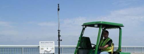
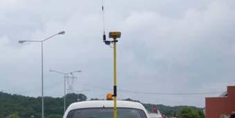
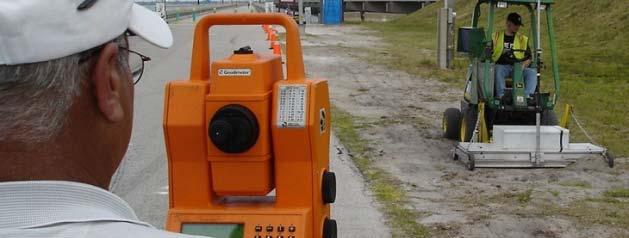
27 Positioning System I Robotic Laser Precise geometry control provided by a self-tracking laser theodolite (robotic total station) locking on to a 360 degree prism 3D accuracy of ±[1 ppm + 1 mm]; for example, ±2 mm in 1 km Range of 2 km Self-tracking, accurate reading every 6 s (faster ones available) Standard technology for construction surveying Survey-grade, can be certified by professional surveyor prism laser theodolite Manufactured by Geodimeter (now Trimble) Nov. 13 th,


 Specified Accuracy with")


28 Positioning System II - GPS Precise geometry control provided by RTK GPS system consisting of base station and rover Accurate reading every second 7.2 km/h (2 m/s) recommended speed (one data point every 2 m) Specified Accuracy with sufficient i Satellite coverage: Horizontal: 10 mm + 1 ppm Vertical: 15 mm + 1 ppm Survey-grade, can be certified by professional surveyor Manufactured by TOPCON (Hiper+ gr-2100) Nov. 13 th,


29 Processing, Integration, Visualization The radar data are processed into geo-referenced seamless 3D radar images Those are interpreted for pipes With the help of complementary information gathered with traditional SUE methods the utility types were identified The clients receive certified CAD maps in plan and profile showing the 3D location of each pipe colored coded by utility Autodesk, Microstation or ArcGIS Nov. 13 th,
30 Please wait for example maps 03_2006_Laura_St_Jak_JEA_Phz1.pdf Nov. 13 th,

 determined by radar")
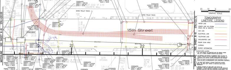
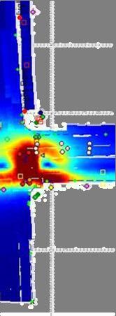
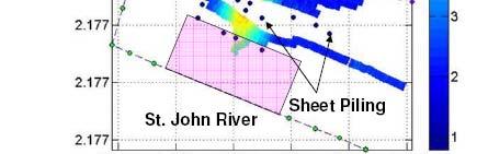
31 Corrected CAD Maps lines not present on original map telephone duct banks off by ten feet of more W 10 ft water line off by several feet Colored lines show utility locations according to available maps. Black lines show actual locations (of selected utilities) determined by radar tomography. Church St Nov. 13 th,
32 Radar Tomography y( (RT) Case Histories Nov. 13 th,
33 Radar Tomography (RT) Example from the Lower Manhattan Radar Project Nov. 13 th,


34 CART Surveys Near WTC West St. Survey Area Areas surveyed in August 2001 Areas surveyed from December 2001 February 8th 2002 Nov. 13 th,


35 Lower Manhattan Radar Project Help in planning reconstruction of the utility network of Lower Manhattan view north along West St view northeast corner of West and Liberty Nov. 13 th,
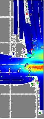
36 roadbed joints 20 ft damaged zone wash outs? surface features manhole and valve covers RADAR IMAGE 2 inches below street level Nov. 13 th,
37 radar shadow of roadbed d joints 20 ft A tops of service boxes RADAR IMAGE 12 inches below street level A Nov. 13 th,
38 radar shadow of roadbed joints 20 ft gas electric RADAR IMAGE 24 inches below street level Nov. 13 th,


39 20 ft water RADAR IMAGE 42 inches below street level Nov. 13 th,
40 Please wait for movie to start Nov. 13 th,


 feet")
41 RT GIS Overview West Street New York City Orthophoto basemap - State Plane (NAD 83) feet Nov. 13 th,
42 Nov. 13 th,
43 Radar Tomography (RT) Case History NYC, Cathedral Parkway Project Nov. 13 th,


44 Cathedral Parkway Project Construction ti Interference Determine if installation of footings for a new walkway along Central Park would require relocation of a high power feeder line Nov. 13 th,
45 Nov. 13 th,


 lines under")

46 view #1 east along walkway Continuouso coverage (mapping) is important t in projects that involve long section of utility lines view #2 northeast #1 DOUGLAS CIRCLE #2 Views of oil-o-static (138kV) lines under Cathedral Parkway near Douglas Circle FRAWLEY CIRCLE Nov. 13 th,
47 Line pair is normally at 36 inches depth except for a short section where it rises to 24 inches (below grade) Map view of lines color indicates depth Nov. 13 th,
48 Cathedral Parkway Mapped ~2000 ft of high-voltage electrical feeder lines over entire length of planned construction ti Cost of $15k ( sq ft at $0.50/sq ft) recovered in fewer test pits needed to verify that construction plan would not affect the lines Number of test pits reduced from 20 (or more) to 5 Cost of a test pit in NYC is about $800 to $3000 Cost Leverage : Reduced risk of having to relocate the lines (a cost of $1 to $3 million) if original maps were inaccurate Nov. 13 th,
49 Electromagnetic Induction Array Concepts Nov. 13 th,

50 Other Transaction Agreement #DTRS56-02-T-0005 Digital Mapping of Buried Pipelines with a Dual-Array System R&D Project funded by Witten Technologies Consolidated d Edison Company of New York U.S. Department of Transportation Research and Special Projects Administration With technical contributions from EMI (a division of Schlumberger) Regional Water Authority of South Central Connecticut Seknion October 2002 December 2004 Nov. 13 th,
51 Mobile platform for urban mapping Nov. 13 th,

")


52 Arrayed Induction Receivers (AIR) System Methodology Electromagnetic Induction Array Accurate Utility Maps Electromagnetic Field Map Nov. 13 th,
53 Electromagnetic Induction Array Systems and Methodology Nov. 13 th,

 Broadband")


 Simultaneous data")
54 Arrayed Induction Receiver (AIR) System Array of 16 broadband vector magnetic field sensors (induction coils) Broadband frequency response Flat from 1 to 80 khz Low noise level khz khz Small package 15 cm 3, about 3 kg Built by EMI (Schlumberger) Simultaneous data acquisition of all 48 channels Nov. 13 th,


![±[1 ppm + 1 mm]; for example, ±2 mm in 1](/docs-images/81/83816474/images/55-2.jpg "km Range of 2 km Self-tracking of 360 deg.")


55 Survey-grade Positioning System BASE STATION PRISM System uses laser theodolite (robotic total station) for survey-grade positioning 3D accuracy of ±[1 ppm + 1 mm]; for example, ±2 mm in 1 km Range of 2 km Self-tracking of 360 deg. prism, accurate reading every 6 s Standard technology for construction surveying Map surface features for local reference map Alternatively use survey-grade GPS Nov. 13 th,
 Current injected directly onto pipe by")


56 EM Source Options Current injection ( clamp-on ) Current injected directly onto pipe by galvanic leads or toroidal clamp Frequencies from 500 Hz to 85 khz Remote induction ( on-board ) Three orthogonal coils of 0.7 m dia. Moment of 5 at 1 khz Frequencies from 500 Hz to 50 khz Reference signal for phase detection Existing signals 60 Hz signals on power lines Nov. 13 th,
57 Electromagnetic Induction Array Case Histories Nov. 13 th,


58 83 khz Lower Hx EM Field Data 0.66m Nov. 13 th,

59 39 khz Total Horizontal EM Field 3.6m 3.3m Nov. 13 th,


60 8.9 khz Total Horizontal EM Field 3.3m 49m 4.9m Nov. 13 th,


61 Dipping Power Line Nov. 13 th,
62 Dipping Power Line Nov. 13 th,
63 EM Complementing Radar Nov. 13 th,

, Radar")


 and the")

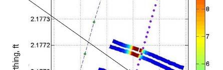
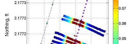
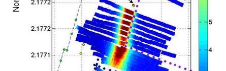
64 Maps and Located Pipes in GIS EM Pipe Picks (gray lines), Radar Pipe Picks (color-coded by depth are superimposed on 65 khz horizontal magnetic field map and 200 MHz Depth Slice at 30 Surface features (symbols) and the curbs in light gray Map was composed in ARCGIS Nov. 13 th,


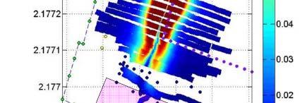
65 Qualitative Pipe Picks Visualized in GIS Pipe Picks (gray lines) are superimposed on 32 khz horizontal magnetic field data map and high- resolution aerial photo (courtesy of RWA) Map was composed in ARCGIS Nov. 13 th,


66 Another GIS Example Nov. 13 th,
67 Subsurface Utility Engineering (SUE) and the Impact of Geophysical Arrays Nov. 13 th,
68 SUE and the Impact of Geophysical Arrays Suggestion to narrow gap between QL B and QL A using: Array-based Surface Geophysical Methods As far as: Continuous Coverage Horizontal and Vertical Position Cost versus Risk Reusable georeferenced digital data Higher COST Lower QL A SUE Quality Levels QL B QL C QL D RISK Higher ih Nov. 13 th,
, more than QL B Risk lower")
69 SUE and the Impact of Geophysical Arrays SUE (QL D, QL C, and QL B) combined with geophysical array technologies (especially RT) have the following advantages: Horizontal and Vertical Position of Utilities typically certified to within 6 inches by WTI professional land surveyor Provide continuous coverage throughout area of interest Cost less than exposure (QL A), more than QL B Risk lower than QL B, almost QL A Reusable geo-referenced digital data improving project design Better-informed more efficient Design Reduces number of exposures (e.g. can guide vacuum excavation) Construction 14% cost reduction, $4.62/$1 ROI* Reduced conflict = fewer change orders Reduced damage = increased safety Faster completion = reduced public nuisance Reduced risk = lower bids Nov. 13 th,

70 Taking advantage of these new technologies' Professional Surveyors certifying results Stronger SUE/ Best Practice mandates (i.e. condition of permit) ROW owners make Project Owners bear the cost of ROW entry Accurate Information AT THE BID: squeeze the risk FDOT: Nov. 13 th,
71 S U M M A R Y 1 Array-based geophysical systems are changing SUE ASCE committee looking into revising i current guidelines FDOT in final step of adopting RT as one of the best practices to be used for certain larger projects Combination of SUE, RT, QL D, QL C, QL B and reduced use of exposures (limited QL A) may proof to be best way to negotiate cost and risk Recommend to: learn and teach about these emerging technologies test and use them in projects for value and cost savings throughout overall project Nov. 13 th,


72 S U M M A R Y 2 Commercial Radar Tomography (RT) Services using the CART Imaging System are offered since early 2001 Deliverables include CAD, Microstation, or GIS subsurface utility maps in 3D located with RT Surveyed several Million of squarefeet over the past 7 years Electromagnetic Induction Array Prototype available for special project to locate deeper conductive utilities Nov. 13 th,


73 WITTEN TECHNOLOGIES, INC. Research & Development 35 Medford d Street, t Suite 306 Somerville, MA r.birken@wittentech.com WITTEN TECHNOLOGIES, INC All rights reserved. Nov. 13 th,
SURVEYING THE UNDERGROUND
 SURVEYING THE UNDERGROUND An Introduction to the Practice of Subsurface Utility Engineering Maryland Society of Surveyors Maryland Society of Professional Engineers Joint Conference October 8, 2015 Michael
SURVEYING THE UNDERGROUND
 SURVEYING THE UNDERGROUND An Introduction to ASCE 38-02 and the Practice of Subsurface Utility Engineering ACECMD March 28, 2018 Presented by: Art Worthman A. Morton Thomas & Associates, Inc. John Berrettini
Subsurface Utility Engineering and 3D Utility Mapping
 Subsurface Utility Engineering and 3D Utility Mapping Subsurface Utility Engineering: A branch of engineering practice that involves managing certain risks associated with utility mapping and appropriate
Strategic City Wide Mapping of Underground Assets using Ground Penetrating Radar. Mark Bell
 Strategic City Wide Mapping of Underground Assets using Ground Penetrating Radar Mark Bell XXV International Federation of Surveyors Congress, Kuala Lumpur, Malaysia, 16 21 June 2014 TOPICS GPR background
Work Type Definition and Submittal Requirements Work Type: Subsurface Utility Engineering (SUE)
") MUST be qualified under Minnesota Department of Transportation Prequalification Program - Work Type 15.1 Subsurface Utility Engineering The first section, Work Type Definition, provides a detailed explanation
MUST be qualified under Minnesota Department of Transportation Prequalification Program - Work Type 15.1 Subsurface Utility Engineering The first section, Work Type Definition, provides a detailed explanation
Advanced Utility Locating Technologies (R01B)
") Advanced Utility Locating Technologies (R01B) Jacob Sheehan Senior Geophysicist Olson Engineering Phil Sirles Principal Geophysicist Olson Engineering Introduction: Utility Bundle Overview SHRP2 Strategic
Advanced Utility Locating Technologies (R01B) Jacob Sheehan Senior Geophysicist Olson Engineering Phil Sirles Principal Geophysicist Olson Engineering Introduction: Utility Bundle Overview SHRP2 Strategic
STATE UNIVERSITY CONSTRUCTION FUND
 DIRECTIVE 1C-12 Issue date: August 2012 1. General SURVEY, MAPPING AND UTILITY LOCATING This Directive has been developed as a general guide for the survey and mapping effort required for Fund projects.
Suveying Lectures for CE 498
 Suveying Lectures for CE 498 SURVEYING CLASSIFICATIONS Surveying work can be classified as follows: 1- Preliminary Surveying In this surveying the detailed data are collected by determining its locations
3D UTILITY MAPPING USING ELECTRONICALLY SCANNED ANTENNA ARRAY. Egil S. Eide and Jens F. Hjelmstad
 D UTILITY MAPPING USING ELECTRONICALLY SCANNED ANTENNA ARRAY Egil S. Eide and Jens F. Hjelmstad Department of Telecommunications Norwegian University of Science and Technology, N-79 Trondheim, Norway eide@tele.ntnu.no
Archaeo-Geophysical Associates, LLC
 Geophysical Survey at the Parker Cemetery Rockwall, Texas. AGA Report 2010-6 Report Submitted To: Texas Cemetery Restoration 10122 Cherry Tree Dr. Dallas, Texas 75243 May 14, 2010 Chester P. Walker, Ph.D.
Report. Mearns Consulting LLC. Former Gas Station 237 E. Las Tunas Drive San Gabriel, California Project # E
 Mearns Consulting LLC Report Former Gas Station 237 E. Las Tunas Drive San Gabriel, California Project #1705261E Charles Carter California Professional Geophysicist 20434 Corisco Street Chatsworth, CA
The use of high frequency transducers, MHz, allowing the resolution to target a few cm thick in the first half meter suspect.
 METHODOLOGY GPR (GROUND PROBING RADAR). In recent years the methodology GPR (Ground Probing Radar) has been applied with increasing success under the NDT thanks to the high speed and resolving power. As
Safety Code 6 (SC6) Measurement Procedures (Uncontrolled Environment)
 Measurement Procedures (Uncontrolled Environment)") February 2011 Spectrum Management and Telecommunications Technical Note Safety Code 6 (SC6) Measurement Procedures (Uncontrolled Environment) Aussi disponible en français NT-329 Contents 1.0 Purpose...1
February 2011 Spectrum Management and Telecommunications Technical Note Safety Code 6 (SC6) Measurement Procedures (Uncontrolled Environment) Aussi disponible en français NT-329 Contents 1.0 Purpose...1
Introduction to Total Station and GPS
 Introduction to Total Station and GPS Dr. P. NANJUNDASWAMY Professor of Civil Engineering J S S Science and Technology University S J College of Engineering Mysuru 570 006 Introduction History GPS Overview
Detection of Pipelines using Sub-Audio Magnetics (SAM)
") Gap Geophysics Australia Pty Ltd. Detection of Pipelines using Sub-Audio Magnetics is a patented technique developed by Gap Geophysics. The technique uses a fast sampling magnetometer to monitor magnetic
Gap Geophysics Australia Pty Ltd. Detection of Pipelines using Sub-Audio Magnetics is a patented technique developed by Gap Geophysics. The technique uses a fast sampling magnetometer to monitor magnetic
Geophysical Survey Rock Hill Bleachery TBA Site Rock Hill, South Carolina EP-W EPA, START 3, Region 4 TABLE OF CONTENTS Section Page Signature
 Geophysical Survey Rock Hill Bleachery TBA Site Rock Hill, South Carolina EP-W-05-054 EPA, START 3, Region 4 Prepared for: Tetra Tech EM, Inc. October 12, 2012 Geophysical Survey Rock Hill Bleachery TBA
In search of a Historic Grave: GPR Investigation near the Yellowstone Lake Store: 7/15/2010
 In search of a Historic Grave: GPR Investigation near the Yellowstone Lake Store: 7/15/2010 Steven Sheriff Professor of Geophysics Department of Geosciences University of Montana Missoula, Montana Introduction
Utility Locating Terminology & Equipment Guide. Utility Survey Corp.
 Utility Locating Terminology & Equipment Guide Utility Survey Corp. Contents Utility Locating Terminology Utility Locating Toning or Scoping Scanning X Ray the Ground & Ground Penetrating Radar 3 4 5 6
November 13, Hindu Temple, LTD Arbor Street Omaha, Nebraska Attn: Subject:
 November 13, 2017 Hindu Temple, LTD 13010 Arbor Street Omaha, Nebraska 68144-0000 Attn: Subject: Srini Mallipudi / mallipudis@gmail.com Underground Utility Survey Report Hindu Temple - 13010 Arbor Street,
CITY OF LOMPOC DEVELOPMENT ASSISTANCE BROCHURE ENCROACHMENT PERMITS AND PUBLIC IMPROVEMENT PLANS
 CITY OF LOMPOC DEVELOPMENT ASSISTANCE BROCHURE E-10 ENCROACHMENT PERMITS AND PUBLIC IMPROVEMENT PLANS The City of Lompoc has determined that the Engineering Division should administer and issue Encroachment
A Report on the Ground Penetrating Radar Survey 205 Little Plains Road Southampton, NY
 A Report on the Ground Penetrating Radar Survey 205 Little Plains Road Southampton, NY November 18, 2016 Conducted by Robert W. Perry TOPOGRAPHIX, LLC Hudson, NH Requested by Southampton Town Historical
UAV PHOTOGRAMMETRY COMPARED TO TRADITIONAL RTK GPS SURVEYING
 UAV PHOTOGRAMMETRY COMPARED TO TRADITIONAL RTK GPS SURVEYING Brad C. Mathison and Amber Warlick March 20, 2016 Fearless Eye Inc. Kansas City, Missouri www.fearlesseye.com KEY WORDS: UAV, UAS, Accuracy
Ground Penetrating Radar (GPR) By Dr. Eng. Zubair Ahmed
 By Dr. Eng. Zubair Ahmed") Ground Penetrating Radar (GPR) By Dr. Eng. Zubair Ahmed Acknowledgement Golder Associates, Whitby, Ontario Stantec Consulting, Kitchener, Ontario Infrasense Inc. USA Geophysical Survey Systems Inc. (GSSI),
Ground Penetrating Radar (GPR) By Dr. Eng. Zubair Ahmed Acknowledgement Golder Associates, Whitby, Ontario Stantec Consulting, Kitchener, Ontario Infrasense Inc. USA Geophysical Survey Systems Inc. (GSSI),
CHAPTER F IVE ROBOTIC TOTAL STATION
 CHAPTER F IVE ROBOTIC TOTAL STATION 5 ROBOTIC TOTAL STATION 5 OVERVIEW If necessity is the mother of invention, then the invention of the Total Station robotic instrument truly fits the requirements of
Old House Channel Bathymetric and Side Scan Survey
 FIELD RESEARCH FACILITY DUCK, NC Old House Channel Bathymetric and Side Scan Survey COASTAL AND HYDRAULICS LABORATORY FIELD DATA COLLECTION AND ANALYSIS BRANCH Michael Forte December 2009 View looking
APPENDIX E INSTRUMENT VERIFICATION STRIP REPORT. Final Remedial Investigation Report for the Former Camp Croft Spartanburg, South Carolina Appendices
 Final Remedial Investigation Report for the Former Camp Croft APPENDIX E INSTRUMENT VERIFICATION STRIP REPORT Contract No.: W912DY-10-D-0028 Page E-1 Task Order No.: 0005 Final Remedial Investigation Report
Covert Tunnel Detection Technologies
 2015 Covert Tunnel Detection Technologies Homeland Security Research Corp. Covert Tunnel Detection Technologies 2015 August 2015 Homeland Security Research Corp. (HSRC) is an international market and technology
Three-dimensional investigation of buried structures with multi-transducer parametric sub-bottom profiler as part of hydrographical applications
 Three-dimensional investigation of buried structures with multi-transducer parametric sub-bottom profiler as part Jens LOWAG, Germany, Dr. Jens WUNDERLICH, Germany, Peter HUEMBS, Germany Key words: parametric,
L A N D R A Y P R O D U C T 1 BREAKTHROUGH PERFORMANCE BY GROUND PENETRATING RADAR
 L A N D R A Y P R O D U C T 1 BREAKTHROUGH PERFORMANCE BY GROUND PENETRATING RADAR 03.2009 Contents LandRay s Business Purpose 3 NEW GENERATION System Requisites 4 LandRay PRODUCT1 best Addresses Unmet
Govt. Engineering College Jhalawar Model Question Paper Subject- Remote Sensing & GIS
 Govt. Engineering College Jhalawar Model Question Paper Subject- Remote Sensing & GIS Time: Max. Marks: Q1. What is remote Sensing? Explain the basic components of a Remote Sensing system. Q2. What is
2012 PURDUE ROAD SCHOOL Session 56. JW Stanger, P.E. Rieth-Riley Construction Co., Inc.
 2012 PURDUE ROAD SCHOOL Session 56 JW Stanger, P.E. Rieth-Riley Construction Co., Inc. GPS Components Base Stations 3D-GPS Rover Pack 3D-GPS Machine Control 3D-millimeter GPS Truck Mounted GPS Using GPS
Applied Geophysics Nov 2 and 4
 Applied Geophysics Nov 2 and 4 Effects of conductivity Surveying geometries Noise in GPR data Summary notes with essential equations Some Case histories EOSC 350 06 Slide 1 GPR Ground Penetrating Radar
GCM mapping Vildbjerg - HydroGeophysics Group - Aarhus University
 GCM mapping Vildbjerg - HydroGeophysics Group - Aarhus University GCM mapping Vildbjerg Report number 06-06-2017, June 2017 Indholdsfortegnelse 1. Project information... 2 2. DUALEM-421s... 3 2.1 Setup
2D/3D Topographic Survey Terrestrial LiDAR (3 Dimensional Laser Scanning)
") SURVEYORS REPORT State Road 91 (Florida s Turnpike) Turnpike Widening from Osceola Parkway to Beachline Specific Purpose Survey Financial Project Identification (FPID) No. s 411406 1 32 01 and 411406 4
SURVEYORS REPORT State Road 91 (Florida s Turnpike) Turnpike Widening from Osceola Parkway to Beachline Specific Purpose Survey Financial Project Identification (FPID) No. s 411406 1 32 01 and 411406 4
Minimum Drawing & Electronic Submittal Requirements For Record Drawings /As-Builts
 Minimum Drawing & Electronic Submittal Requirements For Record Drawings /As-Builts PUBLIC WORKS ENGINEERING DEPARTMENT Revised: February 1, 2017 MINIMUM DRAWING REQUIREMENTS A. GENERAL PLAN REQUIREMENTS:
GPR Part II: Effects of conductivity. Surveying geometries. Noise in GPR data. Summary notes with essential equations. Some Case histories
 GPR Part II: Effects of conductivity Surveying geometries Noise in GPR data Summary notes with essential equations Some Case histories EOSC 350 06 Slide 1 GPR Ground Penetrating Radar R = ε ε 2 2 + ε ε
STANDARD OPERATING PROCEDURES SOP:: 2057 PAGE: 1 of 6 REV: 0.0 DATE: 07/11/03
 PAGE: 1 of 6 1.0 SCOPE AND APPLICATION 2.0 METHOD SUMMARY CONTENTS 3.0 SAMPLE PRESERVATION, CONTAINERS, HANDLING, AND STORAGE 4.0 INTERFERENCES AND POTENTIAL PROBLEMS 5.0 EQUIPMENT/APPARATUS 6.0 REAGENTS
HIGH RESOLUTION STEREO SATELLITE ELEVATION MAPPING ACCURACY ASSESSMENT INTRODUCTION
 HIGH RESOLUTION STEREO SATELLITE ELEVATION MAPPING ACCURACY ASSESSMENT Gerry Mitchell, P. Geo, Geophysicist, President PhotoSat Information Ltd. Vancouver, BC V6E 3S7 gerry@photosat.ca Kevin MacNabb, Geophysicist,
36. Global Positioning System
 36. Introduction to the Global Positioning System (GPS) Why do we need GPS? Position: a basic need safe sea travel, crowed skies, resource management, legal questions Positioning: a challenging job local
Overview. GEM Systems Inc. 135 Spy Crt. Markham Ontario, L3R 5H6 Ph /20/2017 1
 Overview Since 1980, GEM Systems has been the business leader in the advancement of magnetometer technology. GEM is the number one global leader in the manufacture and sale of high precision magnetometers.
STREETSCAPE FEASIBILITY TERMS OF REFERENCE
 Introduction STREETSCAPE FEASIBILITY TERMS OF REFERENCE As outlined in the Official Plan, Section 9, Build A Desirable Urban Form, Mississauga will transform the public realm to create a strong sense of
EKKO_Project is the all-inclusive software SUBSURFACE VIEWS. EKKO_Project V4 Released. In this issue GPR INNOVATIONS HARDWARE AND SOFTWARE
 SUBSURFACE VIEWS GPR INNOVATIONS HARDWARE AND SOFTWARE In this issue 1, 2, 3 EKKO_Project V4 Released 3, 4 EAGE 2015 Boot Camp 5, 6 TIPS: Using the Water Table to Add Topography January, 2016 - Vol. 12,
Chapter 3 Data Acquisition in an Urban Environment
 Chapter 3 Data Acquisition in an Urban Environment - One fundamental issue : cost of data 5-10 times of HW, SW, org ware, staff training, maintenance - Another issue : different kinds of data alphanumeric
USE OF IMPROVISED REMOTELY SENSED DATA FROM UAV FOR GIS AND MAPPING, A CASE STUDY OF GOMA CITY, DR CONGO
 USE OF IMPROVISED REMOTELY SENSED DATA FROM UAV FOR GIS AND MAPPING, A CASE STUDY OF GOMA CITY, DR CONGO Cung Chin Thang United Nations Global Support Center, Brindisi, Italy, Email: thang@un.org KEY WORDS:
Surveyors in The Oil & Gas Industry. Walter Jardine Lead Surveyor, BP North Sea Region Hydrofest 13 April 2011
 Surveyors in The Oil & Gas Industry what on earth do those guys do? Walter Jardine Lead Surveyor, BP North Sea Region Hydrofest 13 April 2011 Why Geography Matters in the O&G Industry Around 80% of the
Survey Requirements. Design Guidelines and Standards. June Office of the University Architect
 Design Guidelines and Standards Survey Requirements June 2004 Office of the University Architect Construction Management P.O. Box 210181 Cincinnati, Ohio 45221-0181 Table of Contents Survey Requirements
Exploration Beyond Expectation. Geo-Carte Radar Technology Pvt. Ltd.
 Exploration Beyond Expectation Geo-Carte Radar Technology Pvt. Ltd. Problem Unknown distribution network of underground pipeline in India 32% Damage of pre-existing underground utilities during laying
HELICOPTER-BORNE GEOPHYSICAL SURVEY SYSTEMS
 HELICOPTER-BORNE GEOPHYSICAL SURVEY SYSTEMS APPLICATIONS: base & precious metals exploration diamondiferous kimberlite exploration geological mapping mapping of fault zones for engineering and mining applications
Using ground penetrating radar to quantify changes in the fracture pattern associated with a simulated rockburst experiment
 Using ground penetrating radar to quantify changes in the fracture pattern associated with a simulated rockburst experiment by M. Grodner* Synopsis Ground Penetrating Radar (GPR) is an electromagnetic
Opera Duo. GeoRadar Division
 Utilities Detection and Mapping Opera Duo: real-time detection of pipes RIS MF Hi-Mod: Utilities mapping on all zones All rights reserved to IDS 2 Utilities Detection and Mapping Stream: massive arrays
MARINE GEOPHYSICAL PROVE-OUT AND SURVEY AT FLAG LAKE BOMBING RANGE BARKSDALE AIR FORCE BASE, LOUISIANA
 MARINE GEOPHYSICAL PROVE-OUT AND SURVEY AT FLAG LAKE BOMBING RANGE BARKSDALE AIR FORCE BASE, LOUISIANA Garrick Marcoux 1, Wallace Robertson 2, Boban Stojanovic 1, Jeffrey B. Hackworth 1 1 FPM Geophysical
7. Consider the following common offset gather collected with GPR.
 Questions: GPR 1. Which of the following statements is incorrect when considering skin depth in GPR a. Skin depth is the distance at which the signal amplitude has decreased by a factor of 1/e b. Skin
Accurate Utility Depth Measurements Using the Spar 300
 Accurate Utility Depth Measurements Using the Spar 3 This Application Note addresses how to obtain accurate subsurface utility depths using the model-based methods employed by the Spar 3. All electromagnetic
Configuration, Capabilities, Limitations, and Examples
 FUGRO EARTHDATA, Inc. Introduction to the New GeoSAR Interferometric Radar Sensor Bill Sharp GeoSAR Regional Director - Americas Becky Morton Regional Manager Configuration, Capabilities, Limitations,
MAKING TRANSIENT ANTENNA MEASUREMENTS
 MAKING TRANSIENT ANTENNA MEASUREMENTS Roger Dygert, Steven R. Nichols MI Technologies, 1125 Satellite Boulevard, Suite 100 Suwanee, GA 30024-4629 ABSTRACT In addition to steady state performance, antennas
MINIMUM DRAWING REQUIREMENTS FOR WATER AND SEWER LINE PROJECTS
 Public Works Department Water & Wastewater Services WATER & WASTEWATER ENGINEERING DIVISION 2555 West Copans Road Pompano Beach, Florida 33369 954-831-0745 FAX 954-831-0798/0925 MINIMUM DRAWING REQUIREMENTS
Helicopter Aerial Laser Ranging
 Helicopter Aerial Laser Ranging Håkan Sterner TopEye AB P.O.Box 1017, SE-551 11 Jönköping, Sweden 1 Introduction Measuring distances with light has been used for terrestrial surveys since the fifties.
Detection of Obscured Targets: Signal Processing
 Detection of Obscured Targets: Signal Processing James McClellan and Waymond R. Scott, Jr. School of Electrical and Computer Engineering Georgia Institute of Technology Atlanta, GA 30332-0250 jim.mcclellan@ece.gatech.edu
Electromagnetic Induction
 Electromagnetic Induction Recap the motivation for using geophysics We have problems to solve Slide 1 Finding resources Hydrocarbons Minerals Ground Water Geothermal Energy SEG Distinguished Lecture slide
CITY OF BEVERLY HILLS Department of Public Works and Transportation Civil Engineering Division SANITARY SEWER IMPROVEMENT PLAN REVIEW CHECKLIST
 CITY OF BEVERLY HILLS Department of Public Works and Transportation Civil ing Division SANITARY SEWER IMPROVEMENT PLAN REVIEW CHECKLIST The following checklist consists of the minimum requirements for
Overview. GEM Systems Inc. 135 Spy Crt. Markham Ontario, L3R 5H6 Ph /4/2016 1
 Overview GEM Systems is celebrating 35 years in business leading the advancement of magnetometer technology. GEM is the number one global leader in the manufacture and sale of high precision magnetometers.
company profile Survey Engineering. COMPANY PROFILE QUALITY GUARANTEE
 company profile Survey Engineering. COMPANY PROFILE QUALITY GUARANTEE Survey Engineering. about us Al Warqa SURVEY ENGINEERING is one of the leading and most advanced surveying companies in United Arab
The Normal Baseline. Dick Gent Law of the Sea Division UK Hydrographic Office
 The Normal Baseline Dick Gent Law of the Sea Division UK Hydrographic Office 2 The normal baseline for measuring the breadth of the territorial sea is the low water line along the coast as marked on large
Advanced Ground Investigation Techniques to Help Limit Risk or Examine Failure. Advanced Subsurface Investigations
 Advanced Ground Investigation Techniques to Help Limit Risk or Examine Failure Overview Introduction What is geophysics? Why use it? Common Methods Seismic Ground Radar Electrical Case Studies Conclusion
GE 113 REMOTE SENSING
 GE 113 REMOTE SENSING Topic 9. Introduction to Global Positioning Systems (GPS) and Other GNSS Technologies Lecturer: Engr. Jojene R. Santillan jrsantillan@carsu.edu.ph Division of Geodetic Engineering
Module 3 Introduction to GIS. Lecture 8 GIS data acquisition
 Module 3 Introduction to GIS Lecture 8 GIS data acquisition GIS workflow Data acquisition (geospatial data input) GPS Remote sensing (satellites, UAV s) LiDAR Digitized maps Attribute Data Management Data
9 LAND SURVEYING. 9.1 General. 9.2 Administrative Requirements Standards Meetings Survey Data Provided to the Design-Builder
 9 LAND SURVEYING 9.1 General The Design-Builder shall conduct all Work necessary to meet the requirements associated with land surveying, including Project and supplemental horizontal and vertical control
GPR SURVEY METHOD. Ground probing radar
 The ground penetrating radar (GPR - Ground Probing Radar) is a geophysical method used to investigate the near surface underground. Thanks to its high degree of resolution, the GPR is the most effective
ME7220A. Radar Test System (RTS) Target Simulation & Signal Analysis for Automotive Radar Exceptional Performance at an Affordable Price.
 Target Simulation & Signal Analysis for Automotive Radar Exceptional Performance at an Affordable Price.") ME7220A Test System (RTS) 76 to 77 GHz Target Simulation & Signal Analysis for Automotive Exceptional Performance at an Affordable Price The Challenge The installation of collision warning and Adaptive
ME7220A Test System (RTS) 76 to 77 GHz Target Simulation & Signal Analysis for Automotive Exceptional Performance at an Affordable Price The Challenge The installation of collision warning and Adaptive
a step change in Ground Penetrating Radar technology Guido Manacorda Engineering Manager
 The ORFEUS Project: a step change in Ground Penetrating Radar technology to locate buried utilities Guido Manacorda Engineering Manager IDS Ingegneria dei Sistemi i SpA Key issues Many ypp pipes and cables
Differential GPS Positioning over Internet
 Abstract Differential GPS Positioning over Internet Y. GAO AND Z. LIU Department of Geomatics Engineering The University of Calgary 2500 University Drive N.W. Calgary, Alberta, Canada T2N 1N4 Email: gao@geomatics.ucalgary.ca
Appendix I Geophysical Survey
 DRAFT IRM PRE- DESIGN INVESTIGATION DATA SUMMARY REPORT NATIONAL GRID FULTON MUNICIPAL WORKS FORMER MGP SITE APRIL 2013 Appendix I Geophysical Survey GEOPHYSICAL SURVEY FULTON MUNICIPAL WORKS FORMER MGP
Emerging Subsea Networks
 FIBRE-TO-PLATFORM CONNECTIVITY, WORKING IN THE 500m ZONE Andrew Lloyd (Global Marine Systems Limited) Email: andrew.lloyd@globalmarinesystems.com Global Marine Systems Ltd, New Saxon House, 1 Winsford
Lessons Learned in Conducting Acoustic Leak Detection Surveys on Water Distribution Systems at 12 Military Installations
 Lessons Learned in Conducting Acoustic Leak Detection Surveys on Water Distribution Systems at 12 Military Installations Harmon Henderson, PE Perry Gayle, PhD, PE, LEED AP 14 April 2015 Presentation Overview
Cooperative navigation: outline
 Positioning and Navigation in GPS-challenged Environments: Cooperative Navigation Concept Dorota A Grejner-Brzezinska, Charles K Toth, Jong-Ki Lee and Xiankun Wang Satellite Positioning and Inertial Navigation
RD1000 Ground Probing Radar
 RD1000 Ground Probing Radar CONTENTS Product Introduction Product Features Competitor Analysis Customers Models, Pricing & Availability Promotional Material Practical Demonstration What to do now Summary
3 Dynatel M Series Locating and Marking System DOCUMENT NEW- TO- THE- WORLD TECHNOLOGY OBSOLETE DAMAGE PREVENTION PIN- POINT ACCURACY SAFETY
 3 Dynatel M Series Locating and Marking System NEW- TO- THE- WORLD TECHNOLOGY PIN- POINT ACCURACY SAFETY DAMAGE PREVENTION Introducing the 3M Dynatel M-iD Series Locating and Marking System. NEW TECHNOLOGY
GPR Data Acquisition and Interpretation
 1 GPR Data Acquisition and Interpretation Mezgeen Rasol PhD Candidate Geophysics and Seismic Engineering Polytechnic University of Catalonia mezgeen.rasol@upc.edu BIG-SKY-EARTH Cost Action TD143 Workshop
Title of Innovation: In-Line Inspection for Water Pipelines
 Title of Innovation: In-Line Inspection for Water Pipelines Nominee(s) Margaret Hannaford, P.E., Division Manager, Hetch-Hetchy Water and Power Division of the San Francisco Public Utilities Commission
ALIS. Project Identification Project name Acronym
 ALIS Project Identification Project name ALIS Acronym Advanced Landmine Imaging System Participation Level National (Japanese) Financed by JST(Japan Science and Technology Agency) Budget N/A Project Type
Improvement of signal to noise ratio by Group Array Stack of single sensor data
 P-113 Improvement of signal to noise ratio by Artatran Ojha *, K. Ramakrishna, G. Sarvesam Geophysical Services, ONGC, Chennai Summary Shot generated noise and the cultural noise is a major problem in
Final Report. Geophysical Characterization of Two UXO Test Sites. submitted to
 DCE-5 Final Report on Geophysical Characterization of Two UXO Test Sites submitted to DPW-Logistics Division USACE Waterways 3909 Halls Ferry Road Vicksburg, MS 3 9 180-6 199 Geophex, Ltd 605 Mercury Street
Estimation results on the location error when using cable locator
 Estimation results on the location error when using cable locator HITOSHI KIJIMA TOMOHIKO HATTORI Tokaigakuin University 5-68 Naka Kirino Kagamigahara, Gifu 504-8511 JAPAN kijima@tokaigakuin-u.ac.jp, t.hattori@tokaigakuin-u.ac.jp
SYSTEM 5900 SIDE SCAN SONAR
 SYSTEM 5900 SIDE SCAN SONAR HIGH-RESOLUTION, DYNAMICALLY FOCUSED, MULTI-BEAM SIDE SCAN SONAR Klein Marine System s 5900 sonar is the flagship in our exclusive family of multi-beam technology-based side
Radar Methods General Overview
 Environmental and Exploration Geophysics II Radar Methods General Overview tom.h.wilson tom.wilson@mail.wvu.edu Department of Geology and Geography West Virginia University Morgantown, WV Brown (2004)
GPR Investigation: Post Tension Cable Mapping
 CMD Civil Pty Ltd PO Box 1119 Huntingdale VIC 3166 +61 3 9544 8833 info@cmdcivil.com www.cmdcivil.com Case Study: GPR Investigation: Post Tension Cable Mapping This application note demonstrates an example
UTILITY LOCATING EQUIPMENT
 RIDGID SEEKTECH LOCATING RECEIVERS RIDGID locating receivers feature an easy-to-use visual mapping display that allows you to locate utility lines and sondes/beacons with confidence. Use with a SeeSnake
Orthoimagery Standards. Chatham County, Georgia. Jason Lee and Noel Perkins
 1 Orthoimagery Standards Chatham County, Georgia Jason Lee and Noel Perkins 2 Table of Contents Introduction... 1 Objective... 1.1 Data Description... 2 Spatial and Temporal Environments... 3 Spatial Extent
ELECTROMAGNETIC FIELD APPLICATION TO UNDERGROUND POWER CABLE DETECTION
 ELECTROMAGNETIC FIELD APPLICATION TO UNDERGROUND POWER CABLE DETECTION P Wang *, K Goddard, P Lewin and S Swingler University of Southampton, Southampton, SO7 BJ, UK *Email: pw@ecs.soton.ac.uk Abstract:
Section E NSPS MODEL STANDARDS FOR TOPOGRAPHIC SURVEYS Approved 3/12/02
 Section E NSPS MODEL STANDARDS FOR TOPOGRAPHIC SURVEYS Approved 3/12/02 1. INTRODUCTION This standard is written to provide the professional surveyor (Surveyor) and the client with a guideline for producing
Leica SmartStation Total Station with integrated GPS
 Leica SmartStation Total Station with integrated GPS Leica SmartStation Total station with integrated GPS New revolutionary surveying system. World s first, TPS and GPS perfectly combined. High performance
CHC MINING DEFORMATION MONITORING SOLUTION
 CHC MINING DEFORMATION MONITORING SOLUTION Safety is first in mining. CHC offers solutions designed to improve safety for personnel on the ground and in the cab with 24/7 precision positioning for automatic
INDEX PREFACE... 1 CAUTIONS... 2 OPERATION ON SITE(9) STANDARD INSTRUMENT... 3 OPTIONAL ACCESSORIES... 4 OPERATION OF TRANSMITTER(3)...
 STANDARD INSTRUMENT... 3 OPTIONAL ACCESSORIES... 4 OPERATION OF TRANSMITTER(3)...") INDEX PREFACE... 1 CAUTIONS... 2 STANDARD INSTRUMENT... 3 OPTIONAL ACCESSORIES... 4 OPERATION OF TRANSMITTER(1)... 5 (Transmitter Unit.) OPERATION OF TRANSMITTER(2)... 6 (Operation Panel, LCD Display of
INDEX PREFACE... 1 CAUTIONS... 2 STANDARD INSTRUMENT... 3 OPTIONAL ACCESSORIES... 4 OPERATION OF TRANSMITTER(1)... 5 (Transmitter Unit.) OPERATION OF TRANSMITTER(2)... 6 (Operation Panel, LCD Display of
Maverick Inspection Ltd. has been pioneering specialized non-destructive testing in Western Canada
 TECHNOLOGY, EXPERTISE & SOLUTIONS Maverick Inspection Ltd. has been pioneering specialized non-destructive testing in Western Canada since 1994. As a Canadian-owned and operated company, we have earned
Division 1 - General Requirements
 Division 1 - General Requirements I - Design Standards 01 30 10 Ground Disturbance Standard Revision Record Ver. Rev. Date Description By Chk d App d* 1 Final Draft CK * Approval sign-off must be from
Advances in NDE Technology WHATS NEW?
 Advances in NDE Technology WHATS NEW? Glen Simula, Owner GS Infrastructure, Inc. The state of America s deteriorating infrastructure presses us to find solutions to assess, with limited funds and resources.
Ground Penetrating Radar
 REPORT 4A Ground Penetrating Radar Introduction to GPR, and positioning of GPR data Part of R&D project Infrastructure in 3D in cooperation between Innovation Norway, Trafikverket and TerraTec Yta för
I am confused by the different models, what are the differences?
 GeoMax Robot Notes A Robotic Total Station (RTS) is one of the most important and most expensive equipment purchases that a surveyor will make. These notes are updated to include commonly and recently
Royal Street Communications, LLC Proposed Base Station (Site No. LA0366A) 315 4th Avenue Venice, California
 315 4th Avenue Venice, California") Statement of Hammett & Edison, Inc., Consulting Engineers The firm of Hammett & Edison, Inc., Consulting Engineers, has been retained on behalf of Royal Street Communications, LLC, a personal wireless
Statement of Hammett & Edison, Inc., Consulting Engineers The firm of Hammett & Edison, Inc., Consulting Engineers, has been retained on behalf of Royal Street Communications, LLC, a personal wireless
Terminology and Acronyms used in ITRC Geophysical Classification for Munitions Response Training
 Terminology and Acronyms used in ITRC Geophysical Classification for Munitions Response Training ITRC s Geophysical Classification for Munitions Response training and associated document (GCMR 2, 2015,