November 13, Hindu Temple, LTD Arbor Street Omaha, Nebraska Attn: Subject:
|
|
|
- Brett Lindsey
- 5 years ago
- Views:
Transcription


1 November 13, 2017 Hindu Temple, LTD Arbor Street Omaha, Nebraska Attn: Subject: Srini Mallipudi / mallipudis@gmail.com Underground Utility Survey Report Hindu Temple Arbor Street, Omaha, Nebraska To: Srini Mallipudi In accordance with your request and authorization, National Ground Penetrating Radar Service, Inc. (NGPRS) conducted a Ground Penetrating Radar (GPR), Electro-Magnetic Induction (EMI), and Global Positioning System (GPS) survey for the above referenced project. Our services included an underground survey, and report. Report data obtained at the site will be held for 3 years at which time data will be discarded. Please advise us in writing if you wish to have us retain them for a longer period. We appreciate the opportunity to have been of service on this project. If there are any questions regarding our review, please contact me Toll Free at (877) Sincerely, NATIONAL GROUND PENETRATING RADAR SERVICE, INC. Stan Liszka Certified Professional Geologist Jared Lampe President
2 SUBSURFACE UTILITY SURVEY REPORT Project Location: Hindu Temple Arbor Street Omaha, Nebraska Prepared for: Hindu Temple, LTD Arbor Street Omaha, Nebraska Prepared by: National Ground Penetrating Radar Service, Inc. Midwest Divsion Headquarters 8400 Normandale Lake Blvd, Suite 920 Minneapolis, Minnesota (952) Project No Report Date: November 13, 2017
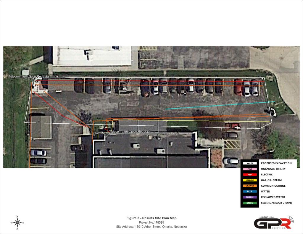
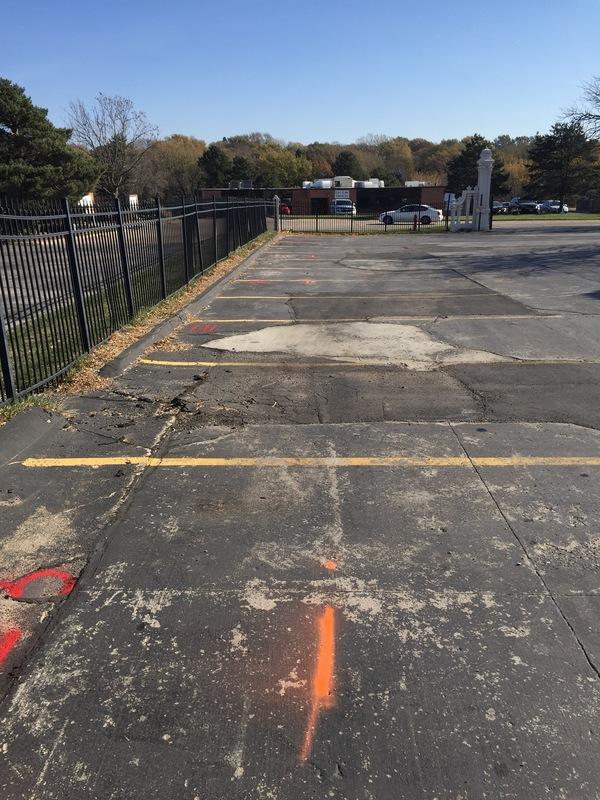
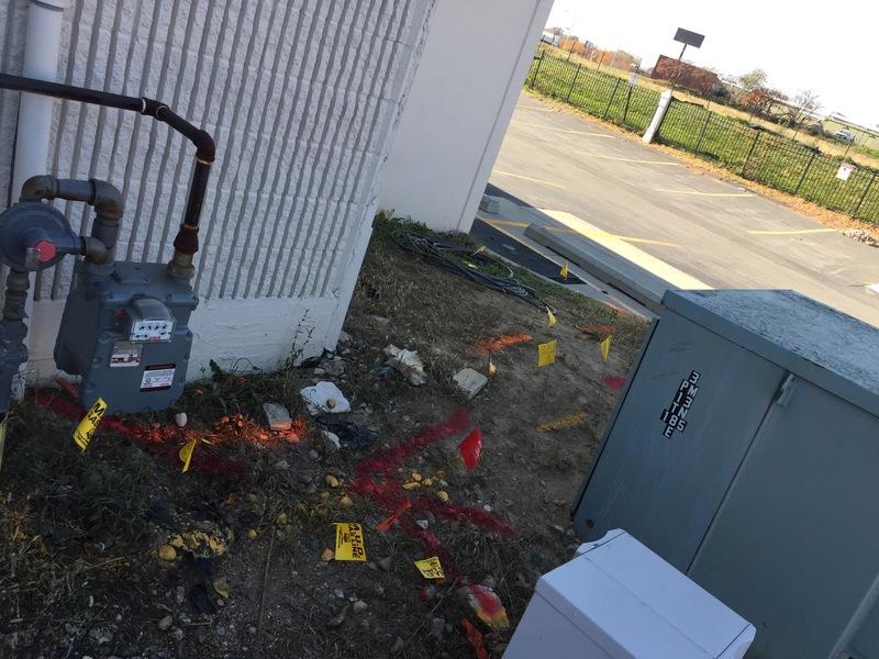
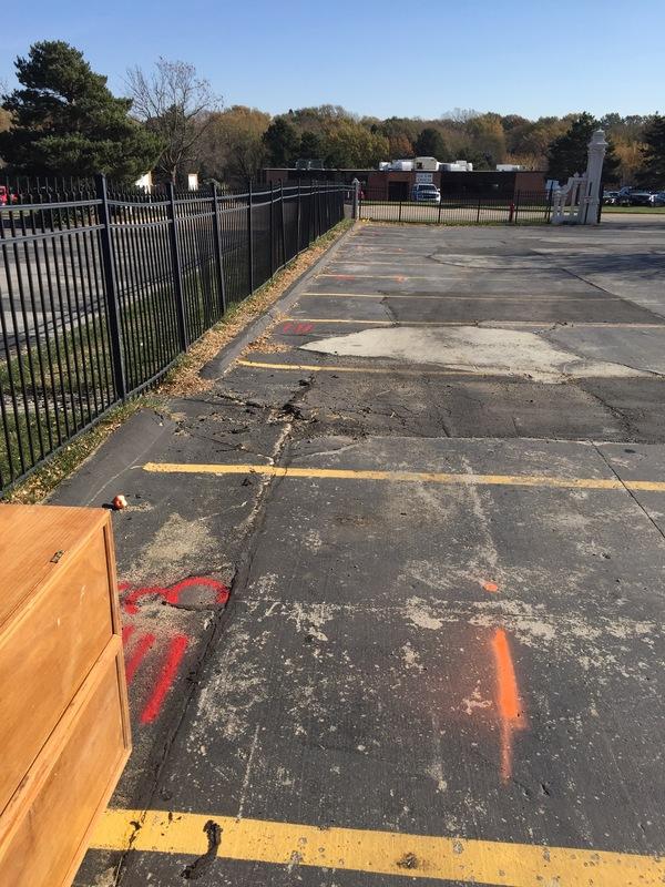
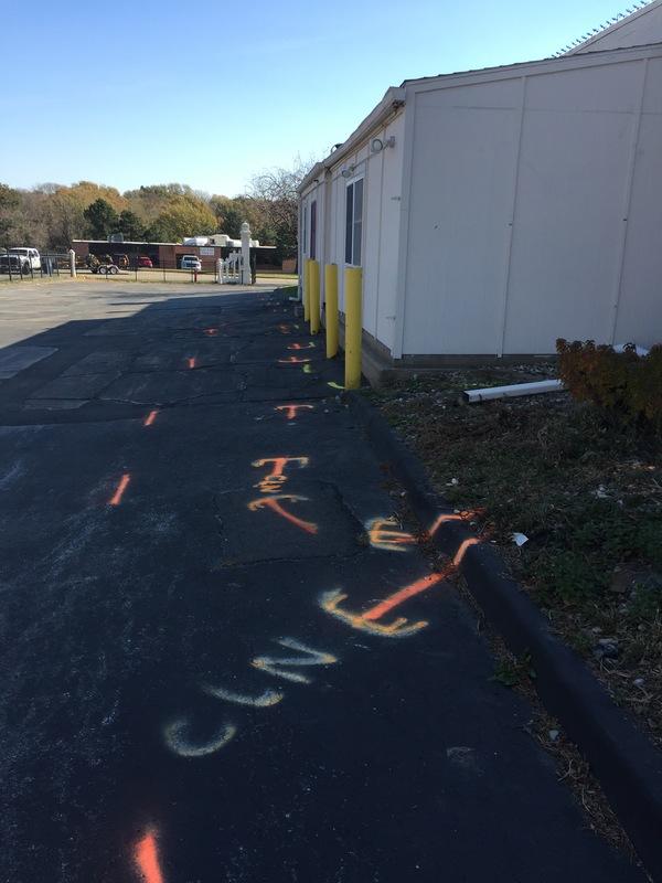
3 Executive Summary National Ground Penetrating Radar Service, Inc. (NGPRS) was retained by Hindu Temple, LTD (HINDU) to perform a Ground Penetrating Radar (GPR), Electro-Magnetic Induction (EMI), and Global Positioning System (GPS) survey at Arbor Street in Omaha, Nebraska. The site is currently used for religous temple purposes, and the survey was conducted over a asphalt covered surface in an exterior area consisting of approximately 14,000 sq. ft. The purpose of the survey was to locate, mark and map underground utilities. Ryan Swartz (NGPRS) performed the field work on November 8, Three (3) energized electrical lines were located at depths ranging from 2-3 ft. below the surface. Electric lines are identified in red in Figure 3. One (1) potential water line was located at a depth ranging from 8 ft. below the surface. Entire line could not be traced as signal was lost due to poor conductivity of pipe connections. Water lines are identified in blue in Figure 3. Two (2) gas lines were located at a depth ranging from 2-3 ft. below the surface. Gas utilities are identified in yellow in Figure 3. No sewer line was located or identified within the survey area(s). Five (5) telecommunication lines were located at depths of 3 ft. below the surface. Telecommunication lines are identified in orange in Figure 3. No additional anomalies were located in the survey area using GPR. All target locations were memorialized using the WGS1984 latitude/longitude coordinate system with accuracy ranging from 23.5 to 53 inches horizontally. We recommend HINDU retain NGPRS to clear additional areas if excavation is to occur outside of the identified survey area. Based on the information presented in this report, we require the following: It is required to use soft dig techniques or hydro excavation if excavating within three (3) feet of any underground utility or anomaly.
4 TABLE OF CONTENTS 1.0 INTRODUCTION Project Description Site Conditions Location and Surface Conditions Subsurface Soil Conditions Scope of Work SURVEY PROCEDURES Equipment Electro Magnetic Induction (EMI) Ground Penetrating Radar (GPR) Global Positioning System (GPS) Software Field Approach RESULTS Electro Magnetic Induction (EMI) Electric Water Gas Sewer Telecommunication Unidentified Ground Penetrating Radar (GPR) Global Positioning System (GPS) RECOMMENDATIONS & REQUIREMENTS LIMITATIONS Electro Magnetic Induction (EMI) Ground Penetrating Radar (GPR) Global Positioning System (GPS) QUALIFICATIONS & DECLARATIONS Declaration Qualifications of the Professional(s) RECORD SOURCES
5 TABLE OF APPENDICES Figure 1 - Vicinity Location Map Figure 2 - Survey Area Site Map Figure 3 - Results Site Plan Map Appendix A - United States Department of Agriculture - GPR Soil Suitability Map Appendix B - Electro Magnetic Induction (EMI) Equipment Settings Appendix C - Ground Penetrating Radar (GPR) Equipment Settings Appendix D - Global Positioning System (GPS) Equipment Settings Appendix E - Photographs Appendix F - Certification of Professional(s)
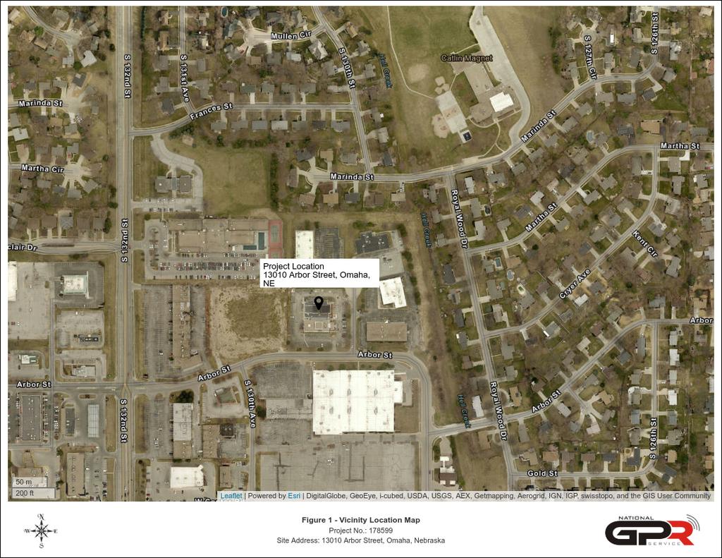
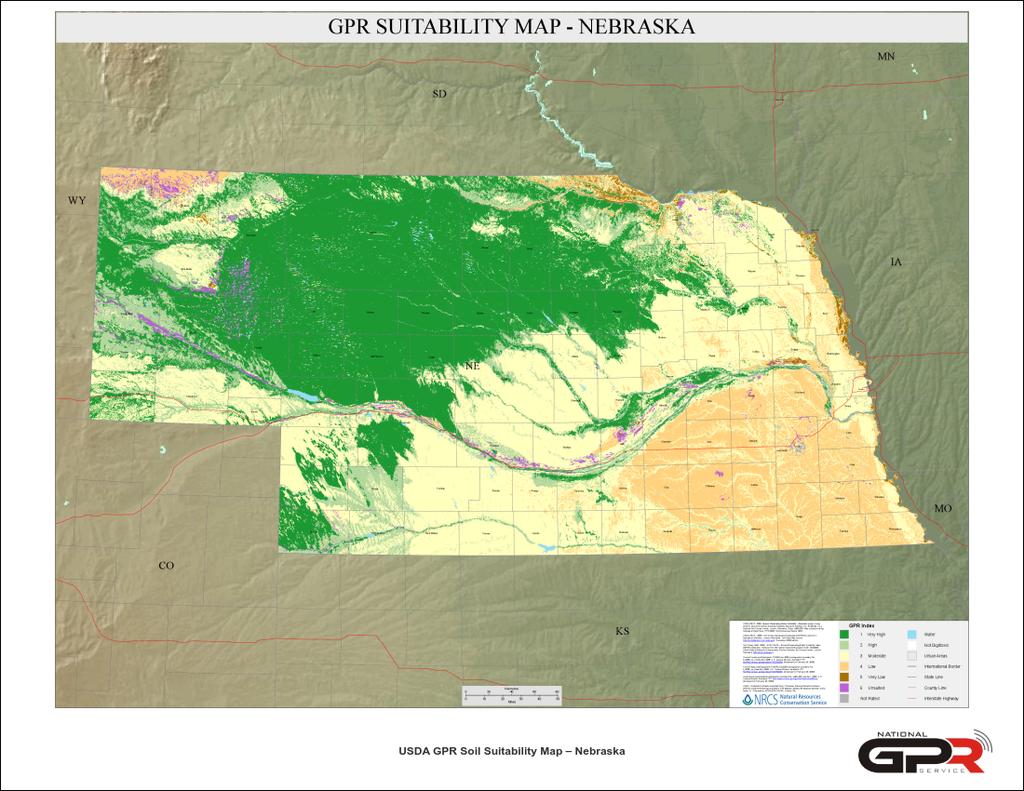
6 1.0 INTRODUCTION National Ground Penetrating Radar Service, Inc. (NGPRS) was retained by Hindu Temple, LTD (HINDU) to perform a Ground Penetrating Radar (GPR), Electro-Magnetic Induction (EMI), and Global Positioning System (GPS) survey at Arbor Street in Omaha, Nebraska. 1.1 Project Description The purpose of the purpose of the project was to locate, mark and map underground utilities. Vicinity Location Map is shown in Figure 1. A 1.2 Site Conditions Location and Surface Conditions The site is located in a rural community north of Arbor Street between S. 132nd Street and S. 130th Circle. The site is currently used for religous gathering purposes. The survey was conducted in an exterior parking lot area on the north end of the building. The subsurface survey was conducted over asphalt covered areas totaling approximately 14,000 sq. ft. No physical limitations to access were encountered in the performance of this subsurface survey. A Survey Area Site Map of the area surveyed is shown in Figure 2. The survey area boundary is outlined using dashed white lines Subsurface Soil Conditions The United States Department of Agriculture GPR Soil Suitability map for Douglas County, Nebraska is shown in Appendix A. The map indicates a GPR survey should produce Low results in native soils. Taking into consideration engineered soil conditions, we anticipated the maximum GPR survey depth to be approximately 4-6 feet. 1.3 Scope of Work Our Scope of Work (SOW) was to perform the following: 1. Perform and underground survey in an exterior, 14,000 sq. ft. area. 2. Use EMI to locate and mark energized underground utilities to a depth of 15 feet below ground surface (bgs). 3. Use GPR to locate and mark non-energized anomalies to a requested survey depth of 9-12 feet bgs. 4. Use GPS to map subsurface target locations. 5. Submit a written report of findings. 1
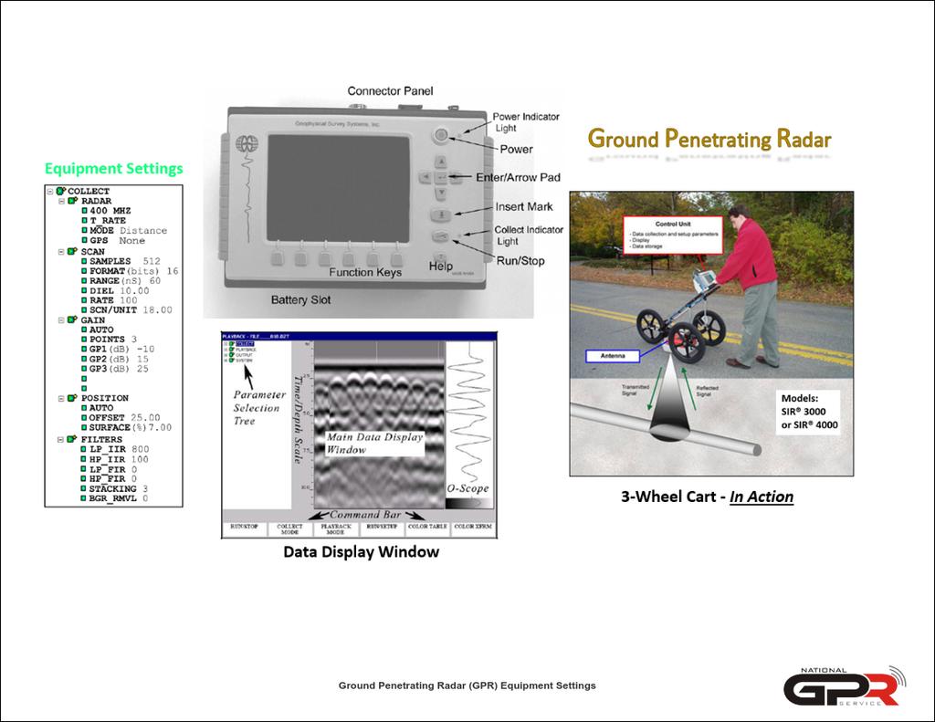
7 2.0 SURVEY PROCEDURES 2.1 Equipment Electro Magnetic Induction (EMI) The EMI survey was conducted using a precision electromagnetic pipe and cable locator, Ridgid SR-20 series. The SR-20 series consists of separate transmitter and receiver. The receiver can be used in "passive" and "active" modes to locate buried pipes by detecting electromagnetic signals carried by the pipes. In the "passive" mode, only the receiver unit is used to detect signals carried by the pipe from nearby power lines, live signals transmitted along underground power cables, or very low frequency radio signals resulting from long wave radio transmissions that flow along buried conductors. In the "active" mode of operation, the transmitter is used to induce a signal on a target pipe, and the receiver is used to trace the signal along the length of the pipe. Our system uses a 5W or 10W transmitter. Equipment and settings are shown in Appendix B Ground Penetrating Radar (GPR) The GPR survey was conducted using a Geophysical Survey Systems, Inc. system (Model SIR3000) using an antenna with central frequency of 400 MHz and a 100 ns time window. The system includes a survey wheel that triggers the recording of the data at fixed intervals, thereby increasing the accuracy of the locations of features detected along the survey lines. GPR uses a high-frequency electromagnetic pulse (referred to herein as radar signal ) transmitted from a radar antenna to probe the subsurface. The transmitted radar signals are reflected from subsurface interfaces of materials with contrasting electrical properties. The travel times of the radar signal can be converted to approximate depth below the surface by correlation with targets of known depths, including stratigraphic horizons, pipes, cables, and other utilities, or by using handbook values of velocities for the materials in the subsurface. The acquisition of GPR data was monitored in the field on a graphic recorder and the real time images were immediately available for field use. The GPR data were also recorded digitally for subsequent processing. Interpretation of the records is based on the nature and intensity of the reflected signals and on the resulting patterns. Equipment and settings are shown in Appendix C Global Positioning System (GPS) The GPS survey was conducted using a Trimble (c) GPS (Model R1) antenna system. The GNSS Bluetooth antenna is designed for mobile devices with WAAS correction. The peripheral GNSS 2
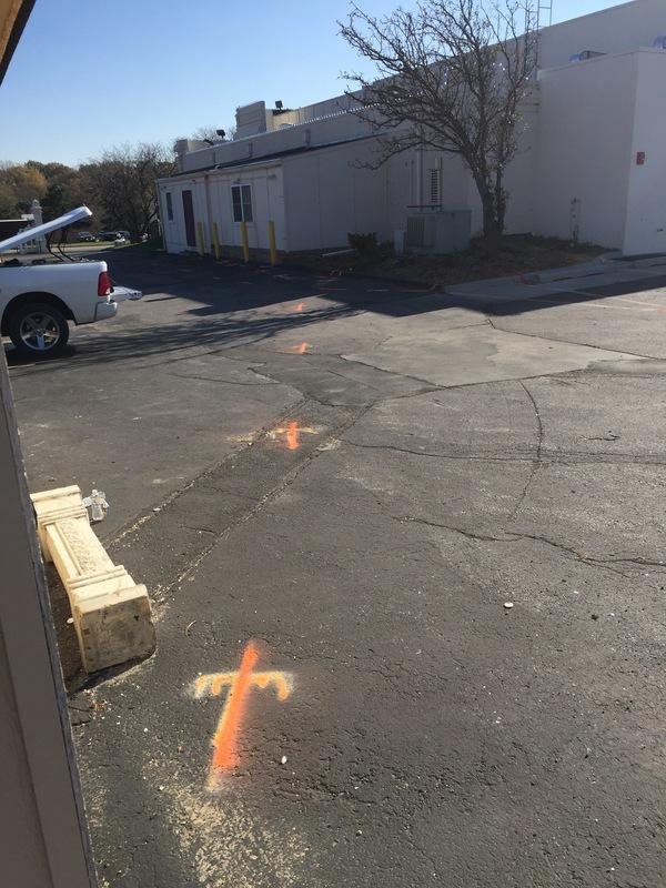
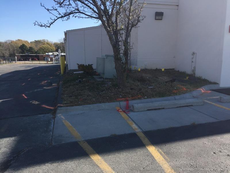
8 receiver pairs with mobile devices such as smart phones, tablets, and other devices. Survey points were recorded using the WGS1984 latitude/longitude coordinate system with sub-meter accuracy. Equipment and settings are shown in Appendix D Software Post processing of any saved GPR data was completed using Geophysical Survey Systems, Inc. RAdar Data ANalyzer (RADAN) software (Version 7.3). GPS data was processed using a Trimble Insphere cloud platform. 2.2 Field Approach Ryan Swartz (NGPRS) performed the field work on November 8, The EMI survey was used to identify, and trace energized utilities in the survey area. GPR was used to verify EMI locations/ depths and determine if any non-energized anomalies were present. Multiple parallel GPR transects were taken in a bi-directional grid pattern using five (5) foot interval spacing. All located utilities were marked on the ground surface using aerosol spray paint and/or flags. 3
9 3.0 RESULTS A Results Site Plan Map and legend is shown in attached Figure Electro Magnetic Induction (EMI) A maximum allowable EMI depth of fifteen (15) feet bgs was achieved at this site using multiple frequencies Electric Three (3) energized electrical lines were located at depths ranging from 2-3 ft. below the surface. Electric lines are identified in red in Figure Water One (1) potential water line was located at a depth ranging from 8 ft. below the surface. Entire line could not be traced as signal was lost due to poor conductivity of pipe connections. Water lines are identified in blue in Figure Gas Two (2) gas lines were located at a depth ranging from 2-3 ft. below the surface. Gas utilities are identified in yellow in Figure Sewer No sewer line was located or identified within the survey area(s) Telecommunication Five (5) telecommunication lines were located at depths of 3 ft. below the surface. Telecommunication lines are identified in orange in Figure Unidentified No sewer utility was located or identified within the survey area(s). 4
10 3.2 Ground Penetrating Radar (GPR) A maximum allowable GPR signal penetration depth of four (4) feet was achieved at this site using the 400 MHz antenna. No anomalies were located in the survey area(s). 3.3 Global Positioning System (GPS) Results of the GPS survey are provided in Google Earth (.kmz) and AutoCAD (.dxf) formats. To download the files, please visit: (LINK TO BE PROVIDED UPON PAYMENT OF FINAL INVOICE). Horizontal accuracy ranged from 23.5 to 53 inches. Geotagged digital photographs are visible in the Google Earth format by left clicking on each survey point. Photographs are also shown in Appendix E. 5
11 4.0 RECOMMENDATIONS & REQUIREMENTS We recommend HINDU retain NGPRS to clear any additional areas if excavation is to occur outside of the identified survey area. Based on the information presented in this report, we require the following: It is required to use soft dig techniques or hydro excavation if excavating within three (3) feet of any underground utility or anomaly. 6
12 5.0 LIMITATIONS NATIONAL GROUND PENETRATING RADAR SERVICE, INC. (NGPRS) MAKES NO GUARANTEE THAT ALL SUBSURFACE TARGETS OF INTEREST WERE DETECTED IN THIS SURVEY. NGPRS IS NOT RESPONSIBLE FOR DETECTING SUBSURFACE TARGETS THAT NORMALLY CANNOT BE DETECTED BY THE METHODS EMPLOYED OR THAT CANNOT BE DETECTED BECAUSE OF SITE CONDITIONS. GPR SIGNAL PENETRATION MAY NOT BE DEEP ENOUGH TO DETECT SOME TARGETS. NGPRS IS NOT RESPONSIBLE FOR MAINTAINING FIELD MARKOUTS AFTER LEAVING THE WORK AREA. HINDUUNDERSTANDS THAT MARK-OUTS MADE DURING INCLEMENT WEATHER OR IN AREAS OF HIGH PEDESTRIAN OR VEHICULAR TRAFFIC MAY NOT LAST. Field mark-outs. Utilities detected by the EMI method at the time of the survey are marked in the field, and the operator makes every attempt, field conditions permitting, to detect and mark as many utilities as possible at the time of survey. Adverse weather and site conditions (rain, snow, snow and soil piles, uneven surfaces, high traffic, etc.) can hamper in-field interpretation. Utility mark-outs made on wet pavement, snow, snow piles, gravel surfaces, or in active construction zones may not last. NGPRS is not responsible for maintaining utility mark-outs after leaving the work area. 5.1 Electro Magnetic Induction (EMI) The EMI equipment cannot detect non-metallic utilities, such as pipes constructed of vitrified clay, plastic, PVC, fiberglass, and unreinforced concrete, when used in passive mode alone. Such pipes can be detected if a wire tracer is installed with access to such tracer for transmission of a signal or where access (such as floor drains and clean-outs) permits insertion of a device on which a signal can be transmitted. In some, but not all, cases, the subsurface utility designation equipment cannot detect metal utilities reliably under reinforced concrete because the signal couples onto the metal reinforcing in the concrete. Similarly, the method commonly cannot be used adjacent to grounded metal structures such as chain link fences and metal guardrails. In congested areas, where several utilities are bundled or located within a short distance, the signal transmitted on one utility can couple onto adjacent utilities, and the accuracy of the location indicated by the instrument decreases. 5.2 Ground Penetrating Radar (GPR) There are limitations of the GPR technique as used to detect and/or locate targets such as those of the objectives of this survey: (1) surface conditions, (2) electrical conductivity of the ground, (3) contrast 7
13 of the electrical properties of the target and the surrounding soil, and (4) spacing of the traverses. Of these restrictions, only the last is controllable by us. The condition of the ground surface can affect the quality of the GPR data and the depth of penetration of the GPR signal. Sites covered with snow piles, high grass, bushes, landscape structures, debris, obstacles, soil mounds, etc. limit the survey access and the coupling of the GPR antenna with the ground. In many cases, the GPR signal will not penetrate below concrete pavement, especially inside buildings, and a target may not be detectable. The electrical conductivity of the ground determines the attenuation of the GPR signals, and thereby limits the maximum depth of exploration. For example, the GPR signal does not penetrate clay-rich soils, and targets buried in clay might not be detected. A definite contrast in the electrical conductivities of the surrounding ground and the target material is required to obtain a reflection of the GPR signal. If the contrast is too small, possibly due to construction details or deeply corroded metal in the target, then the reflection may be too weak to recognize and the target can be missed. In many cases, plastic, clay, asbestos concrete (transite), brick-lined, stone-lined, and other non-metallic utilities are extremely difficult to detect. Spacing of the transects is limited by access at many sites, but where flexibility of transect spacing is possible, the spacing is adjusted to the size of the target. The GPR operator controls the spacing between lines, and the design of the survey is based on the dimensions of the smallest feature of interest, and budgetary controls. GPR surveys typically require one (1) inch diameter of target for every one (1) inch of survey depth to be detectable. 5.3 Global Positioning System (GPS) Information regarding GPS limitations is provided on the National Oceanic and Atmospheric Administration website at 8
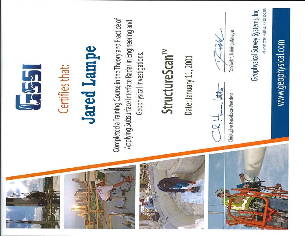
14 6.0 QUALIFICATIONS & DECLARATIONS 6.1 Declaration The conclusions in the report are predicated on observation and testing of the earthwork and/or construction of the foundation under the direction of the Certified Individual of record. Opinions are based on data assumed representative of the site. We do not warranty conditions below the depth of equipment readings. Recommendations represented in this report should be verified and approved by a designated engineer of record. We declare that, to the best of our professional knowledge and belief, we have performed the GPR survey in accordance with American Society of Testing and Material (ASTM) D Guide for Using the Surface Ground Penetrating Radar Method for Subsurface Investigation, and the GPR & EMI survey in accordance with American Society of Civil Engineers (ASCE) Standard Guideline for the Collection and Depiction of Existing Subsurface Utility Data Quality Level B results, and we have the specific qualifications based on education, training, and experience to perform a project of the nature, history, and setting of the Site. 6.2 Qualifications of the Professional(s) The site survey was conducted by Ryan Swartz who is a certified GPR operator. Stan Liszka, CPG assisted in the preparation of this report, and Jared Lampe, President reviewed the contents of this report. Staff certification qualifications are shown in attached Appendix F. 9
15 7.0 RECORD SOURCES Imagery displayed on the Figures was obtained through 2017 Google Earth a computer application that renders a 3D representation of Earth based on satellite imagery. All imagery and/ or maps used by NGPRS used in this report conforms with the attribution guidelines for Google Maps and Google Earth explained at the following website geoguidelines/attr-guide.html. 10
16 Figure 1 - Vicinity Location Map

17
18 Figure 2 - Survey Area Site Map

19
20 Figure 3 - Results Site Plan Map
21
22 Appendix A - United States Department of Agriculture - GPR Soil Suitability Map

23
24 Appendix B - Electro Magnetic Induction (EMI) Equipment Settings
25
26 Appendix C - Ground Penetrating Radar (GPR) Equipment Settings
27
28 Appendix D - Global Positioning System (GPS) Equipment Settings
29
30 Appendix E - Photographs


31 1 : Photo 2 : Photo 3 : Photo 4 : Photo


32 5 : Photo 6 : Photo 7 : Photo 8 : Photo


33 9 : Photo 10 : Photo 11 : Photo 12 : Photo

34 13 : Photo 14 : Photo
35 Appendix F - Certification of Professional(s)
36
37

38 Ryan Swartz 2008
Appendix I Geophysical Survey
 DRAFT IRM PRE- DESIGN INVESTIGATION DATA SUMMARY REPORT NATIONAL GRID FULTON MUNICIPAL WORKS FORMER MGP SITE APRIL 2013 Appendix I Geophysical Survey GEOPHYSICAL SURVEY FULTON MUNICIPAL WORKS FORMER MGP
Report. Mearns Consulting LLC. Former Gas Station 237 E. Las Tunas Drive San Gabriel, California Project # E
 Mearns Consulting LLC Report Former Gas Station 237 E. Las Tunas Drive San Gabriel, California Project #1705261E Charles Carter California Professional Geophysicist 20434 Corisco Street Chatsworth, CA
SURVEYING THE UNDERGROUND
 SURVEYING THE UNDERGROUND An Introduction to ASCE 38-02 and the Practice of Subsurface Utility Engineering ACECMD March 28, 2018 Presented by: Art Worthman A. Morton Thomas & Associates, Inc. John Berrettini
Geophysical Survey Rock Hill Bleachery TBA Site Rock Hill, South Carolina EP-W EPA, START 3, Region 4 TABLE OF CONTENTS Section Page Signature
 Geophysical Survey Rock Hill Bleachery TBA Site Rock Hill, South Carolina EP-W-05-054 EPA, START 3, Region 4 Prepared for: Tetra Tech EM, Inc. October 12, 2012 Geophysical Survey Rock Hill Bleachery TBA
STATE UNIVERSITY CONSTRUCTION FUND
 DIRECTIVE 1C-12 Issue date: August 2012 1. General SURVEY, MAPPING AND UTILITY LOCATING This Directive has been developed as a general guide for the survey and mapping effort required for Fund projects.
SURVEYING THE UNDERGROUND
 SURVEYING THE UNDERGROUND An Introduction to the Practice of Subsurface Utility Engineering Maryland Society of Surveyors Maryland Society of Professional Engineers Joint Conference October 8, 2015 Michael
A Report on the Ground Penetrating Radar Survey 205 Little Plains Road Southampton, NY
 A Report on the Ground Penetrating Radar Survey 205 Little Plains Road Southampton, NY November 18, 2016 Conducted by Robert W. Perry TOPOGRAPHIX, LLC Hudson, NH Requested by Southampton Town Historical
GPR SURVEY METHOD. Ground probing radar
 The ground penetrating radar (GPR - Ground Probing Radar) is a geophysical method used to investigate the near surface underground. Thanks to its high degree of resolution, the GPR is the most effective
Archaeo-Geophysical Associates, LLC
 Geophysical Survey at the Parker Cemetery Rockwall, Texas. AGA Report 2010-6 Report Submitted To: Texas Cemetery Restoration 10122 Cherry Tree Dr. Dallas, Texas 75243 May 14, 2010 Chester P. Walker, Ph.D.
In search of a Historic Grave: GPR Investigation near the Yellowstone Lake Store: 7/15/2010
 In search of a Historic Grave: GPR Investigation near the Yellowstone Lake Store: 7/15/2010 Steven Sheriff Professor of Geophysics Department of Geosciences University of Montana Missoula, Montana Introduction
The use of high frequency transducers, MHz, allowing the resolution to target a few cm thick in the first half meter suspect.
 METHODOLOGY GPR (GROUND PROBING RADAR). In recent years the methodology GPR (Ground Probing Radar) has been applied with increasing success under the NDT thanks to the high speed and resolving power. As
Work Type Definition and Submittal Requirements Work Type: Subsurface Utility Engineering (SUE)
") MUST be qualified under Minnesota Department of Transportation Prequalification Program - Work Type 15.1 Subsurface Utility Engineering The first section, Work Type Definition, provides a detailed explanation
MUST be qualified under Minnesota Department of Transportation Prequalification Program - Work Type 15.1 Subsurface Utility Engineering The first section, Work Type Definition, provides a detailed explanation
AGENDA Cemetery Board 206 Toronto St. S., Markdale, Ontario June 11, :00 p.m.
 AGENDA Cemetery Board 206 Toronto St. S., Markdale, Ontario June 11, 2008-4:00 p.m. Page 1. CALL TO ORDER 2. ADDITIONS TO OR DELETIONS FROM THE AGENDA 3. ADOPTION OF AGENDA 4. DECLARATION OF CONFLICT OR
UTILITY LOCATING EQUIPMENT
 RIDGID SEEKTECH LOCATING RECEIVERS RIDGID locating receivers feature an easy-to-use visual mapping display that allows you to locate utility lines and sondes/beacons with confidence. Use with a SeeSnake
Ground Penetrating Radar (GPR) By Dr. Eng. Zubair Ahmed
 By Dr. Eng. Zubair Ahmed") Ground Penetrating Radar (GPR) By Dr. Eng. Zubair Ahmed Acknowledgement Golder Associates, Whitby, Ontario Stantec Consulting, Kitchener, Ontario Infrasense Inc. USA Geophysical Survey Systems Inc. (GSSI),
Ground Penetrating Radar (GPR) By Dr. Eng. Zubair Ahmed Acknowledgement Golder Associates, Whitby, Ontario Stantec Consulting, Kitchener, Ontario Infrasense Inc. USA Geophysical Survey Systems Inc. (GSSI),
Advanced Ground Investigation Techniques to Help Limit Risk or Examine Failure. Advanced Subsurface Investigations
 Advanced Ground Investigation Techniques to Help Limit Risk or Examine Failure Overview Introduction What is geophysics? Why use it? Common Methods Seismic Ground Radar Electrical Case Studies Conclusion
Utility Locating Terminology & Equipment Guide. Utility Survey Corp.
 Utility Locating Terminology & Equipment Guide Utility Survey Corp. Contents Utility Locating Terminology Utility Locating Toning or Scoping Scanning X Ray the Ground & Ground Penetrating Radar 3 4 5 6
Advanced Utility Locating Technologies (R01B)
") Advanced Utility Locating Technologies (R01B) Jacob Sheehan Senior Geophysicist Olson Engineering Phil Sirles Principal Geophysicist Olson Engineering Introduction: Utility Bundle Overview SHRP2 Strategic
Advanced Utility Locating Technologies (R01B) Jacob Sheehan Senior Geophysicist Olson Engineering Phil Sirles Principal Geophysicist Olson Engineering Introduction: Utility Bundle Overview SHRP2 Strategic
Radiodetection. Fundamental principles and techniques in buried utility location
 Fundamental principles and techniques in buried utility location Canada 344 Edgeley Blvd. Unit 34 Concord, Ontario L4K 4B7 1-800-665-7953 Pipe and Cable Locators don't find pipes and cables...? 2 ...they
3D UTILITY MAPPING USING ELECTRONICALLY SCANNED ANTENNA ARRAY. Egil S. Eide and Jens F. Hjelmstad
 D UTILITY MAPPING USING ELECTRONICALLY SCANNED ANTENNA ARRAY Egil S. Eide and Jens F. Hjelmstad Department of Telecommunications Norwegian University of Science and Technology, N-79 Trondheim, Norway eide@tele.ntnu.no
3 Dynatel M Series Locating and Marking System DOCUMENT NEW- TO- THE- WORLD TECHNOLOGY OBSOLETE DAMAGE PREVENTION PIN- POINT ACCURACY SAFETY
 3 Dynatel M Series Locating and Marking System NEW- TO- THE- WORLD TECHNOLOGY PIN- POINT ACCURACY SAFETY DAMAGE PREVENTION Introducing the 3M Dynatel M-iD Series Locating and Marking System. NEW TECHNOLOGY
Products. Locating DAMAGE PREVENTION
 Products Locating DAMAGE PREVENTION UT 9000 The new standard for damage prevention and pipe location easy always efficient A new dimension in pipe location When it comes to locating underground pipes and
GPR SYSTEM USER GUIDE AND TROUBLESHOOTING GUIDE
 GPR SYSTEM USER GUIDE AND TROUBLESHOOTING GUIDE Implementation Report 5-4414-01-1 Project Number 5-4414-01 Subsurface Sensing Lab Electrical and Computer Engineering University of Houston 4800 Calhoun
Radar Methods General Overview
 Environmental and Exploration Geophysics II Radar Methods General Overview tom.h.wilson tom.wilson@mail.wvu.edu Department of Geology and Geography West Virginia University Morgantown, WV Brown (2004)
SECTION SITE SURVEYS
 SECTION 02 21 13 SITE SURVEYS SPEC WRITER NOTE: 1. Delete text between // // not applicable to project. Edit remaining text to suit project. 2. Use this section to specify survey required before design
Results of GPR survey of AGH University of Science and Technology test site (Cracow neighborhood).
.") Results of GPR survey of AGH University of Science and Technology test site (Cracow neighborhood). October 02, 2017 Two GPR sets were used for the survey. First GPR set: low-frequency GPR Loza-N [1]. Technical
Results of GPR survey of AGH University of Science and Technology test site (Cracow neighborhood). October 02, 2017 Two GPR sets were used for the survey. First GPR set: low-frequency GPR Loza-N [1]. Technical
Exploration Beyond Expectation. Geo-Carte Radar Technology Pvt. Ltd.
 Exploration Beyond Expectation Geo-Carte Radar Technology Pvt. Ltd. Problem Unknown distribution network of underground pipeline in India 32% Damage of pre-existing underground utilities during laying
CITY OF LOMPOC DEVELOPMENT ASSISTANCE BROCHURE ENCROACHMENT PERMITS AND PUBLIC IMPROVEMENT PLANS
 CITY OF LOMPOC DEVELOPMENT ASSISTANCE BROCHURE E-10 ENCROACHMENT PERMITS AND PUBLIC IMPROVEMENT PLANS The City of Lompoc has determined that the Engineering Division should administer and issue Encroachment
Diamond Knowledge Base. Inductive Loop Guide. Introduction
 Diamond Knowledge Base Inductive Loop Guide Introduction An inductive loop is basically a metal detector installed in the surface of the roadway. It consists of electrical wire embedded in the roadway,
HAMILTON TOWNSHIP Department of Planning and Zoning Application for a Commercial / Industrial Site Plan Review
 HAMILTON TOWNSHIP Department of Planning and Zoning Application for a Commercial / Industrial Site Plan Review Date: Application is hereby made for a Site Plan Review for a commercial or industrial use.
SSPC-PA 2 Procedure for Determining Conformance to Dry Coating Thickness Requirements
 SSPC-PA 2 Procedure for Determining Conformance to Dry Coating Thickness Requirements William D. Corbett, KTA-Tator, Inc. Chair SSPC Committee C.3.2 on Dry Film Thickness Measurement SSPC-PA 2 Procedure
GPR Investigation: Post Tension Cable Mapping
 CMD Civil Pty Ltd PO Box 1119 Huntingdale VIC 3166 +61 3 9544 8833 info@cmdcivil.com www.cmdcivil.com Case Study: GPR Investigation: Post Tension Cable Mapping This application note demonstrates an example
MILL HILL ARTS VILLAGE
 OWNER CIVIL ENGINEER MACON-BIBB URBAN DEVELOPMENT AUTHORITY ALEX MORRISON, EXECUTIVE DIRECTOR 200 CHERRY STREET, SUITE 300 MACON, GA 31201 OFFICE PHONE : (478) 803-2402 TRIPLE POINT ENGINEERING DAN WALLACE,
Using ground penetrating radar to quantify changes in the fracture pattern associated with a simulated rockburst experiment
 Using ground penetrating radar to quantify changes in the fracture pattern associated with a simulated rockburst experiment by M. Grodner* Synopsis Ground Penetrating Radar (GPR) is an electromagnetic
SPECIFICATIONS FOR THE INSTALLATION OF CONDUIT SYSTEMS IN RESIDENTIAL SUBDIVISIONS. Notification of Completed Conduit Sections
 SPECIFICATIONS FOR THE INSTALLATION OF CONDUIT SYSTEMS IN RESIDENTIAL SUBDIVISIONS Section 1 Definitions 2 Scope of Work 3 Extent of Work 4 Inspection and Performance of Work 5 Trenching 6 Duct Installation
Survey Requirements. Design Guidelines and Standards. June Office of the University Architect
 Design Guidelines and Standards Survey Requirements June 2004 Office of the University Architect Construction Management P.O. Box 210181 Cincinnati, Ohio 45221-0181 Table of Contents Survey Requirements
GPR Data Acquisition and Interpretation
 1 GPR Data Acquisition and Interpretation Mezgeen Rasol PhD Candidate Geophysics and Seismic Engineering Polytechnic University of Catalonia mezgeen.rasol@upc.edu BIG-SKY-EARTH Cost Action TD143 Workshop
SEMI-PRIVACY PANEL AND GATE INSTALLATION INSTRUCTIONS
 SEMI-PRIVACY PANEL AND GATE INSTALLATION INSTRUCTIONS 1 BEFORE YOU START, IT S IMPORTANT TO CHECK: That fence or the fence post footings do not exceed your lot lines of your property. If you can locate
Last Name: First Name: M.I:
 ARCHITECTURE DESIGN REVIEW BOARD APPLICATION OFFICE USE ONLY APPLICATION # Permit # Fee Collected $ 1. Filing Status Initial Submission Amendment Withdrawal 2. Cost of Construction (Industry Standards)
Case Studies and Innovative Uses of GPR for Pavement Engineering Applications
 Case Studies and Innovative Uses of GPR for Pavement Engineering Applications Richard Korczak, MASc., P.Eng., Stantec Consulting Ltd. Amir Abd El Halim, PhD., P.Eng., Stantec Consulting Ltd. Paper prepared
LAB 9: GROUND-PENETRATING RADAR
 NAME: LAB TIME: LAB 9: GROUND-PENETRATING RADAR The following lab will introduce you to the basic concepts of Ground-Penetrating Radar (GPR) in part I. In part II, we will conduct a field geophysical survey
GROUND PENETRATING RADAR AND THE SURVEYOR w/ Case Studies
 GROUND PENETRATING RADAR AND THE SURVEYOR w/ Case Studies Joseph D. Fenicle, PS Ohio & Michigan Professional Surveyor Office of the Fulton County Engineer Wauseon, Ohio Angular By Nature, LLC Adrian, MI
Armada Technologies Pro800D Hi-Power Wire and Valve Locator. Operating Instructions
 Test Equipment Depot - 800.517.8431-99 Washington Street Melrose, MA 02176 TestEquipmentDepot.com Armada Technologies Pro800D Hi-Power Wire and Valve Locator Armada T echnologies Operating P ro800d Instructions
Subsurface Utility Engineering and 3D Utility Mapping
 Subsurface Utility Engineering and 3D Utility Mapping Subsurface Utility Engineering: A branch of engineering practice that involves managing certain risks associated with utility mapping and appropriate
C.A.T and Genny User Guide. Revision
 C.A.T and Genny User Guide Revision 3-06.00 Troubleshooting When reporting any problem to your Radiodetection Dealer/Supplier it is important to quote the Receiver Serial Number. Warning: Radiodetection
ARCHAEOLOGICAL GEOPHYSICS: SENSOR SELECTION AND SITE SUITABILITY
 ARCHAEOLOGICAL GEOPHYSICS: SENSOR SELECTION AND SITE SUITABILITY A SPARC Webinar presented on October 17, 2014 Eileen G. Ernenwein, PhD ETSU: http://faculty.etsu.edu/ernenwei/ CAST: http://goo.gl/wyzlp
B.2 MAJOR SUBDIVISION PRELIMINARY PLAN CHECKLIST
 B.2 MAJOR SUBDIVISION PRELIMINARY PLAN CHECKLIST YES* GENERAL SUBMISSION ITEMS Does the submission include: 1. Thirteen (13) copies of completed Application Form? 2. Thirteen (13) copies of the Preliminary
SIMULATION OF GPR SCENARIOS USING FDTD
 SIMULATION OF GPR SCENARIOS USING FDTD 1 GAMIL ALSHARAHI, 2 ABDELLAH DRIOUACH, 3 AHMED FAIZE 1,2 Department of physic, Abdelmalek Essaâdi University, Faculty of sciences, Morocco 3 Department of physic,
CONCEPT REVIEW GUIDELINES
 Department of Planning & Community Development @ Jefferson Station 1526 E. Forrest Avenue Suite 100 East Point, GA 30344 404.270.7212 (Phone) 404.765.2784 (Fax) www.eastpointcity.org CONCEPT REVIEW GUIDELINES
7. Consider the following common offset gather collected with GPR.
 Questions: GPR 1. Which of the following statements is incorrect when considering skin depth in GPR a. Skin depth is the distance at which the signal amplitude has decreased by a factor of 1/e b. Skin
Article 4 PROCEDURES for PLOT PLAN and SITE PLAN REVIEW
 Article 4 PROCEDURES for PLOT PLAN and SITE PLAN REVIEW Section 4.01 Purpose It is the intent of this Article to specify standards, application and data requirements, and the review process which shall
SUBSURFACE MAPPING. Presenters: Thomas Kevin Hanna, PLS. Paul J. Emilius Jr., PLS CP
 SUBSURFACE MAPPING Presenters: Thomas Kevin Hanna, PLS Paul J. Emilius Jr., PLS CP February 2 nd 2011 1 Existing Underground Utilities Abound! Power, Telecommunications, Gas/Propane, Petroleum, Sanitary
Methodological guidelines for the use of ground penetrating radars
 Methodological guidelines for the use of ground penetrating radars Series 3, Software version 3.8.1.0 Transient Technologies 2004 2015 Transient Technologies LLC office 604, 13, Maryny Raskovoi str., Kyiv,
SITE PLAN, SUBDIVISION & EXTERIOR DESIGN REVIEW PROCESS
 INCORPORATED VILLAGE OF ROCKVILLE CENTRE BUILDING DEPARTMENT SITE PLAN, SUBDIVISION & EXTERIOR DESIGN REVIEW PROCESS Presubmission - Prior to a formal submission, the applicant should meet in person with
OPEN PICKET PANEL AND GATE INSTALLATION INSTRUCTIONS
 For All Your Vinyl Fencing Needs OPEN PICKET PANEL AND GATE INSTALLATION INSTRUCTIONS 1 BEFORE YOU START, IT S IMPORTANT TO CHECK: That fence or the fence post footings do not exceed your lot lines of
A Rapid Photo Point Monitoring Method
 A Rapid Photo Point Monitoring Method Pat Reece, Prairie & Montane Enterprises patreece@prairieme.com Tonya Haigh, National Drought Mitigation Center thaigh2@unl.edu Goal: To document the effects that
Get To The Point. Faster!
 99 Washington Street Melrose, MA 02176 Phone 781-665-1400 Toll Free 1-800-517-8431 Visit us at www.testequipmentdepot.com TM SeekTech SR-20 Line Locator Locate underground utility lines with speed, accuracy
INSTRUCTIONS: 1. Record the transmittal letter number, date, and subject on the transmittal record sheet located in the front of the manual.
 MINNESOTA DEPARTMENT OF TRANSPORTATION DEVELOPED BY: Design Standards ISSUED BY: Office of Technical Support Design Services Section TRANSMITTAL LETTER NO. (0-03) MANUAL: Standard Plates DATED: September
Strategic City Wide Mapping of Underground Assets using Ground Penetrating Radar. Mark Bell
 Strategic City Wide Mapping of Underground Assets using Ground Penetrating Radar Mark Bell XXV International Federation of Surveyors Congress, Kuala Lumpur, Malaysia, 16 21 June 2014 TOPICS GPR background
SSPC-PA 2 Procedure for Determining Conformance to Dry Coating Thickness Requirements
 SSPC-PA 2 Procedure for Determining Conformance to Dry Coating Thickness Requirements William D. Corbett, KTA-Tator, Inc. Chair SSPC Committee C.3.2 on Dry Film Thickness Measurement SSPC-PA 2 Procedure
MINIMUM DRAWING REQUIREMENTS FOR WATER AND SEWER LINE PROJECTS
 Public Works Department Water & Wastewater Services WATER & WASTEWATER ENGINEERING DIVISION 2555 West Copans Road Pompano Beach, Florida 33369 954-831-0745 FAX 954-831-0798/0925 MINIMUM DRAWING REQUIREMENTS
Estimation results on the location error when using cable locator
 Estimation results on the location error when using cable locator HITOSHI KIJIMA TOMOHIKO HATTORI Tokaigakuin University 5-68 Naka Kirino Kagamigahara, Gifu 504-8511 JAPAN kijima@tokaigakuin-u.ac.jp, t.hattori@tokaigakuin-u.ac.jp
SUBSURFACE INSTRUMENTS, INC. AML PRO & AML+ PRODUCT GUIDE
 SUBSURFACE INSTRUMENTS, INC. AML PRO & AML+ PRODUCT GUIDE Advanced Underground PVC Pipe Detection Patented Technology Advanced PVC & PE Pipe Detection FCC, IC & EU/CE Approved www.ssilocators.com INTRODUCING
Section E NSPS MODEL STANDARDS FOR TOPOGRAPHIC SURVEYS Approved 3/12/02
 Section E NSPS MODEL STANDARDS FOR TOPOGRAPHIC SURVEYS Approved 3/12/02 1. INTRODUCTION This standard is written to provide the professional surveyor (Surveyor) and the client with a guideline for producing
Instruction Manual CXL Locator DXL Locator MXL Locator SGA Signal Generator SGV Signal Generator MXT Transmitter
 Cable Avoidance Tool AS Cable Avoidance Tool Depth Measuring Cable Avoidance Tool AS Depth Measuring Cable Avoidance Tool AS Precision Pipe & Cable Locator Precision Pipe & Cable Locator PRECISION PIPE
SIR, UtilityScan and RADAN are registered trademarks of Geophysical Survey Systems, Inc.
 Copyright 2016-2017 Geophysical Survey Systems, Inc. All rights reserved including the right of reproduction in whole or in part in any form Published by Geophysical Survey Systems, Inc. 40 Simon Street
Opera Duo. GeoRadar Division
 Utilities Detection and Mapping Opera Duo: real-time detection of pipes RIS MF Hi-Mod: Utilities mapping on all zones All rights reserved to IDS 2 Utilities Detection and Mapping Stream: massive arrays
Town of Skowhegan Application For Development Review
 Town of Skowhegan Application For Development Review Return to: Skowhegan Planning Office 225 Water St., Skowhegan, ME 04976 (207) 474-6904 skowcodesec@skowhegan.org To be filled in by Staff: Project Name:
Section 101. Street Design
 Section 101 Street Design This section establishes the uniform policies and procedures for the preparation of street design plans and construction requirements in the City of Irvine. It is not intended
Appendix F: Archaeology VEIRS MILL CORRIDOR MASTER PLAN PUBLIC HEARING DRAFT
 Appendix F: Archaeology VEIRS MILL CORRIDOR MASTER PLAN PUBLIC HEARING DRAFT Appendix - Archaeology Summary In 1838, Samuel Clark Veirs constructed a mill on Rock Creek along the south side of the one-lane
RD8100 OPTIMUM PRECISION FOR DAMAGE PREVENTION
 PRECISION locators RD8100 OPTIMUM PRECISION FOR DAMAGE PREVENTION Since Radiodetection launched the first commercial, twin antenna, cable and pipe locators over 40 years ago, we have pioneered many technologies
DITCH WITCH LOCATORS
 DITCH WITCH LOCATORS YOUR WINDOW TO THE UNDERGROUND. DITCH WITCH 950R/T and 970T Pipe and Cable Locator System Like real estate, underground construction is all about location, location, location. The
Installing a COMROD AS1R Whip Antenna with Anchor Post
 Installing a COMROD AS1R Whip Antenna with Anchor Post IS10012 Issue 1.0...15 September 2010 Nautel Limited 10089 Peggy's Cove Road, Hackett's Cove, NS, Canada B3Z 3J4 T.877 6 nautel (628835) or +1.902.823.2233
1. Report No. FHWA/TX-05/ Title and Subtitle PILOT IMPLEMENTATION OF CONCRETE PAVEMENT THICKNESS GPR
 1. Report No. FHWA/TX-05/5-4414-01-3 4. Title and Subtitle PILOT IMPLEMENTATION OF CONCRETE PAVEMENT THICKNESS GPR Technical Report Documentation Page 2. Government Accession No. 3. Recipient s Catalog
Date Requested, 200_ Work Order No. Funding source Name of project Project limits: Purpose of the project
 Bureau of Engineering SURVEY DIVISION REQUEST FOR TOPOGRAPHIC SURVEY Date Requested, 200_ Work Order No. Funding source Name of project Project limits: Purpose of the project Caltrans involvement (must
General Warnings Non-Metallic Pipe Tracing Features Depth Measurement Locator Operating Modes Signal Current Measurement Function Checks
 CXL4 Cable Avoidance Tool DXL4 Depth Measuring Cable Avoidance Tool SGA4 Signal Generator SGV4 Signal Generator MXL4 Precision Pipe & Cable Locator MXT4 Transmitter INSTRUCTION MANUAL Contents General
P Forsmark site investigation. RAMAC and BIPS logging in borehole HFM11 and HFM12
 P-04-39 Forsmark site investigation RAMAC and BIPS logging in borehole HFM11 and HFM12 Jaana Gustafsson, Christer Gustafsson Malå Geoscience AB/RAYCON March 2004 Svensk Kärnbränslehantering AB Swedish
SUMMIT COUNTY PLANNING AND ENGINEERING DEPARTMENT
 SUMMIT COUNTY PLANNING AND ENGINEERING DEPARTMENT SINGLE-FAMILY SITE PLAN INFORMATION PACKET GENERAL INFORMATION This information packet explains how your application for a single-family site plan will
CITY OF BEVERLY HILLS Department of Public Works and Transportation Civil Engineering Division SANITARY SEWER IMPROVEMENT PLAN REVIEW CHECKLIST
 CITY OF BEVERLY HILLS Department of Public Works and Transportation Civil ing Division SANITARY SEWER IMPROVEMENT PLAN REVIEW CHECKLIST The following checklist consists of the minimum requirements for
Report on a Ground Penetrating Radar survey of Longyearbreen
 Report on a Ground Penetrating Radar survey of Longyearbreen AT-329 Unis, 10.03.2006 Christopher Nuth Karen Klemetsrud Matthias Hofmann Tone Gulliksen Øy Abstract: Ground Penetration Radar was used to
Planning and Zoning Application & Checklist
 City of Driggs, Idaho Planning & Zoning 60 S. Main Street PO Box 48 Driggs, ID 83422 Ph: (208) 354-2362 Fax: (208) 354-8522 www.driggs.govoffice.com Planning and Zoning Application & Checklist DESIGN REVIEW
CITY OF BEVERLY HILLS Department of Public Works and Transportation Civil Engineering Division STORM DRAIN IMPROVEMENT PLAN REVIEW CHECKLIST
 CITY OF BEVERLY HILLS Department of Public Works and Transportation Civil ing Division STORM DRAIN IMPROVEMENT PLAN REVIEW CHECKLIST The following checklist consists of the minimum requirements for preparation
Opera Duo. Opera Duo. GeoRadar Division. a first class underground survey
 a first class underground survey Opera Duo Competitive advantages Designed around you A large, comfortable handle to make pushing an pulling easier, large wheels for better control and a balanced weight
Rezoning/OCP Amendment Application. Current OCP Designation. Proposed OCP Designation
 Development Permit Application Rezoning/OCP Amendment Application Zoning DP Area yes no Variances Requested Development Details Property Size (m² or ha) Current Zoning Current OCP Designation Proposed
Existing and proposed contours at 1-foot intervals. The fill and/or excavation quantities in cubic yards.
 PLAN REQUIREMENTS The plans for street design shall conform to the requirements of Sections 3 and 4. The following requirements shall also be shown on the plans where applicable. Road and Storm Plans:
Dowel Alignment: Measurement and Impacts on Pavement Performance
 Dowel Alignment: Measurement and Impacts on Pavement Performance prepared by: Mark B. Snyder, Ph.D., P.E. Vice-President, ACPA-PA Chapter for: ACPA s 2012 Annual Meeting Concrete Pavement University November
FINAL GEOPHYSICAL SURVEY REPORT CATLIN CEMETERY AND HISTORIC TRAILS PEABODY, KANSAS
 FINAL GEOPHYSICAL SURVEY REPORT CATLIN CEMETERY AND HISTORIC TRAILS PEABODY, KANSAS MARCH 2010 Prepared by: FPM Geophysical & UXO Services 5559 NW Barry Rd. #251 Kansas City, Missouri 64154 March 29, 2010
STREETSCAPE FEASIBILITY TERMS OF REFERENCE
 Introduction STREETSCAPE FEASIBILITY TERMS OF REFERENCE As outlined in the Official Plan, Section 9, Build A Desirable Urban Form, Mississauga will transform the public realm to create a strong sense of
Golden Mask Deep Hunter LE
 Golden Mask Deep Hunter LE Golden mask Deep Hunter LE is a pulse induction detector, designed for easy detection of deeply buried large metal objects (larger than 8 cm or 3 ) with LED indication for the
Identification of Pipelines from the Secondary Reflect Wave Travel Time of Ground-Penetrating Radar Waves
 Journal of Emerging Trends in Engineering and Applied Sciences (JETEAS) 2 (5): 770-774 Scholarlink Research Institute Journals, 2011 (ISSN: 2141-7016) jeteas.scholarlinkresearch.org Journal of Emerging
OVER-HEIGHT FENCE/RETAINING WALL CERTIFICATION APPLICATION
 OVER-HEIGHT FENCE/RETAINING WALL CERTIFICATION APPLICATION Application information below to be completed by Applicant/Agent//Owner APN PROPERTY ADDRESS PROPERTY LOCATION (if no address) APPLICANT S NAME
Investigation of Bridge Decks Utilizing Ground Penetrating Radar
 Investigation of Bridge Decks Utilizing Ground Penetrating Radar Steve Cardimona *, Brent Willeford *, John Wenzlick +, Neil Anderson * * The University of Missouri-Rolla, Department of Geology and Geophysics
Georgia Underground Marking Standards
 Georgia Underground Marking Standards PSC RULE 515-9-4.14 414 GUFPA PSC Rules AGENDA Marking Standards d Sufficient Particularity Educational Materials GUFPA Law and PSC Rule GUFPA- Dig Law Passed by the
SITE PLAN Application Packet (Required For All Non-Residential Development Projects)
") SITE PLAN Application Packet (Required For All Non-Residential Development Projects) Community Development Department 90 North Main Street, Tooele, UT 84074 (435) 843-2130 Fax (435) 843-2139 Dear Applicant,
SITE PLAN Application Packet (Required For All Non-Residential Development Projects) Community Development Department 90 North Main Street, Tooele, UT 84074 (435) 843-2130 Fax (435) 843-2139 Dear Applicant,
Tri-band ground penetrating radar for subsurface structural condition assessments and utility mapping
 Tri-band ground penetrating radar for subsurface structural condition assessments and utility mapping D. Huston *1, T. Xia 1, Y. Zhang 1, T. Fan 1, J. Razinger 1, D. Burns 1 1 University of Vermont, Burlington,
Power Quality. Case Study. Conrad Bottu Laborelec January 2008
 Case Study Electromagnetic compatibility (EMC) study Breakdown of low voltage electronic equipment in a 25 kv substation Conrad Bottu Laborelec January 2008 Power Quality Power Quality 1 Introduction Description
List of Figures. List of Forms
 City of Columbia Engineering Regulations PART 1: SUBMISSION OF PLANS Table of Contents Paragraph Description Page No. 1.1 General 1-1 1.2 Engineer s Report 1-1 1.3 Plans 1-3 1.4 Revisions to Approved Plan
RADAR INSPECTION OF CONCRETE, BRICK AND MASONRY STRUCTURES
 RADAR INSPECTION OF CONCRETE, BRICK AND MASONRY STRUCTURES C.P.Hobbs AEA Industrial Technology Materials and Manufacturing Division Nondestructive Testing Department Building 447 Harwell Laboratory Oxon
Applying for a Site Development Review
 Guide What is it? Applying for a Who approves it? ensures that new buildings or land uses are compatible with their sites and with the surrounding environment, other development, and traffic circulation.
Advances in NDE Technology WHATS NEW?
 Advances in NDE Technology WHATS NEW? Glen Simula, Owner GS Infrastructure, Inc. The state of America s deteriorating infrastructure presses us to find solutions to assess, with limited funds and resources.