SSPC-PA 2 Procedure for Determining Conformance to Dry Coating Thickness Requirements
|
|
|
- Dortha Cole
- 6 years ago
- Views:
Transcription

1 SSPC-PA 2 Procedure for Determining Conformance to Dry Coating Thickness Requirements William D. Corbett, KTA-Tator, Inc. Chair SSPC Committee C.3.2 on Dry Film Thickness Measurement
2 SSPC-PA 2 Procedure for Determining Conformance to Dry Coating Thickness Requirements Webinar Content Background of SSPC PA 2 Overview and Purpose of SSPC-PA 2 (2012) Purpose of ASTM D Definitions Gage Descriptions Calibration, Verification of Accuracy & Adjustment Measurement Procedures Frequency and Number of Measurements Conformance to Specified Thickness Content of Eight Appendices
3 Learning Objectives/Outcomes Completion of this webinar will enable the participant to: Describe the purpose and content of SSPC-PA 2 Describe the differences between Type 1 and Type 2 gages Describe the processes associated with calibration, verification of accuracy and adjustment Explain Base Metal Reading acquisition Describe the frequency and tolerance of measurements Describe the procedure for determining the magnitude of a nonconforming area Describe the basic content of eight appendices to the standard
 Most recent update was 2004 Editorial revision to an")

4 Background of SSPC-PA 2 Originally published in SSPC Volume 2 in 1973(T) Most recent update was 2004 Editorial revision to an Appendix in 2009 SSPC committee work on revisions initiated in 2007 Current version dated May 1, 2012 Standard re-balloted in August/September 2013
 focuses on acceptability of acquired measurements Both address ferrous and non-ferrous metal")
5 Background of SSPC-PA 2 Update to ASTM D concurrent with revisions to SSPC-PA 2 ASTM D focuses on gage use SSPC-PA 2 (2012) focuses on acceptability of acquired measurements Both address ferrous and non-ferrous metal surfaces
6 Scope of SSPC-PA 2 Describes a procedure for determining shop/field conformance to a specified DFT range on ferrous and non-ferrous metals Measurements are acquired using commercially available gages (two types ) Procedures for gage calibration, verification of accuracy and adjustment are described Procedure for determining conformance to specified thickness range over extended areas is described
7 Scope of SSPC-PA 2 Standard contains 8 non-mandatory appendices (described later) 9 th appendix was recently balloted (precautions regarding the use of the standard for coating failure investigations) Standard is not intended to be used for measurement of thermal spray coatings (procedure described in SSPC-CS 23.00)
 diameter circle Area Measurement: The average of five spot measurements over each 100 square feet of coated")
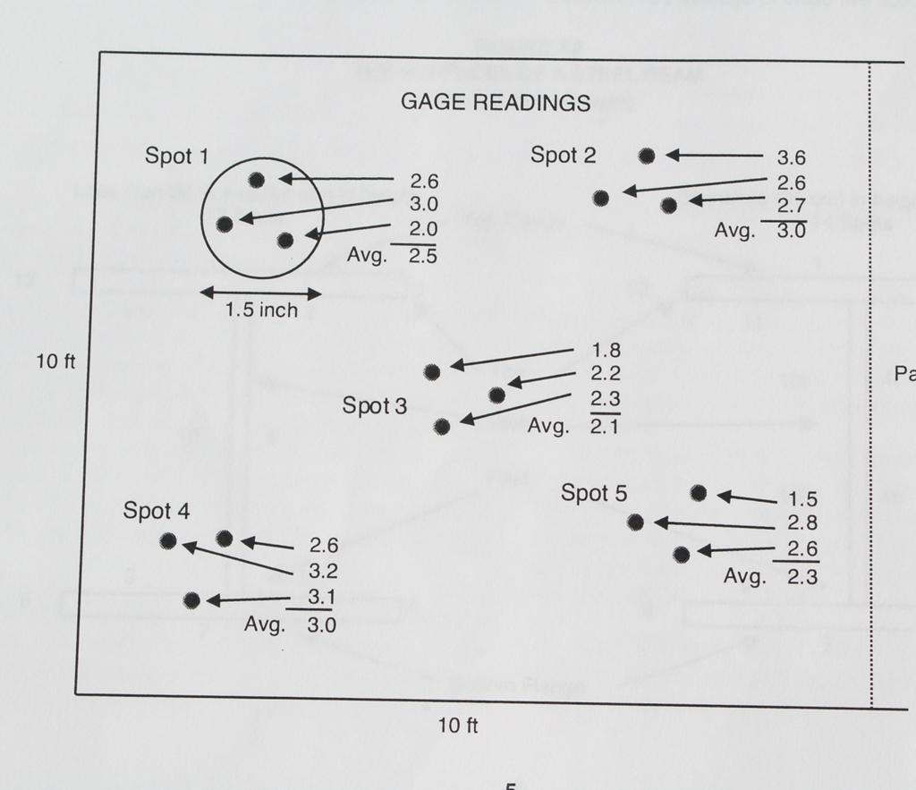
8 Definitions in SSPC-PA 2 Gage Reading: A single instrument reading Spot Measurement: The average of three or at least three gage readings made within a 1 ½ (4 cm) diameter circle Area Measurement: The average of five spot measurements over each 100 square feet of coated surface
9 Gage Descriptions Gage type is determined by magnetic properties employed to measure thickness (not the read-out mode) Type 1 Magnetic Pull-off Gages Type 2 Electronic Gages


10 Gage Types Type 1 Magnetic Pull-off Gages Type 2 Electronic Gages
11 Gage Types, continued Type 1 Magnetic Pulloff Gages Permanent magnet contacts coated surface Force required to detach magnet is measured Force interpreted as the coating thickness on scale or display Scale is nonlinear


12 Gage Types, continued Type 2 Electronic Gages Electronic circuitry converts reference signal to coating thickness
13 Calibration & Verification of Accuracy ASTM D7091 describes 3 operational steps to ensure accurate measurement: Calibration Verification of Accuracy Adjustment Steps are required to be completed before coating thickness data acquisition to determine conformance to a specification
14 Gage Calibration Performed by the gage manufacturer or an accredited calibration laboratory Test certificate traceable to a National Metrology institution required No standard calibration interval (established based on experience & work environment) One year interval is common

, if: Record: Obtaining a large no.")

15 Verification of Type 1 Gage Accuracy Performed as described in ASTM D7091 Beginning and end of each work shift (minimum) During (e.g., hourly), if: Record: Obtaining a large no. of readings Gage is dropped or readings are suspect Serial no. of gage & standard Stated & measured thickness Method used to verify accuracy
16 Verification of Type 1 Gage Accuracy Type 1 gages should not be adjusted Adjustments to the helical spring may void the gage warranty Combined tolerance of gage and coated standard determines gage accuracy E.g., if gage accuracy is 5% and reference standard accuracy is 3%, combined tolerance is ~ 6%, calculated as: On a 10 mil reference standard, the gage reading can range from mils
17 Correction for Surface Roughness Base Metal Reading (BMR) Effect of surface roughness on coating thickness gage NOT surface profile Measure the prepared, uncoated substrate; calculate average BMR Deduct BMR from measured coating thickness BMR
 7 25 µm (1.0 mil) 8 28 µm (1.1 mils) 9 23 µm (0.9 mil) 10 13 µm (0.")
18 Correction for Surface Roughness Area BMR 1 30 µm (1.2 mils) 2 25 µm (1.0 mils) 3 18 µm (0.7 mil) 4 13 µm (0.5 mil) 5 20 µm (0.8 mil) 6 8 µm (0.3 mil) 7 25 µm (1.0 mil) 8 28 µm (1.1 mils) 9 23 µm (0.9 mil) µm (0.5 mil) Measuring Base Metal Effect with Type 1 DFT Gage Average BMR: 21 µm (0.8 mil)
19 BMR Correction for Multiple Coat Systems Measured Primer Thickness: BMR: Actual Primer Thickness: 102 µm (4.0 mils) 13 µm (0.5 mils) 89 µm (3.5 mils) Measured Primer + Finish Thickness: BMR: Actual Total System Thickness: 178 µm (7.0 mils) 13 µm (0.5 mils) 165 µm (6.5 mils)
20 Correction for Surface Roughness What if access to blast cleaned steel is not available (already coated)? Appendix A8.3 addresses smooth surface adjustment Verify gage accuracy on a smooth surface (per gage manufacturer instructions) Deduct assumed approximate correction value from each gage reading
21 Correction for Surface Roughness Table A8 Typical Gage Correction Values Using ISO 8503 Profile Grades ISO 8503 Profile Grade Correction Value (µm) Correction value (mils) Fine Medium Coarse
 During (e.g., hourly), if: Record: Obtaining a large no. of readings Gage is dropped or readings are suspect Serial no.")
22 Verification of Type 2 Gage Accuracy Verify accuracy per manufacturer instructions (use coated standards) Performed as described in ASTM D7091 Beginning and end of each work shift (minimum) During (e.g., hourly), if: Record: Obtaining a large no. of readings Gage is dropped or readings are suspect Serial no. of gage & standard Stated & measured thickness
23 Verification of Type 2 Gage Accuracy Single Point Verification Select one reference coated standard representing the mid-range of the anticipated coating thickness E.g., 4-6 mils ( µm), select 5 mil (125 µm) reference standard Tw0 Point Verification Select reference coated standards below and above the median anticipated coating thickness E.g., 5 mils (125 µm), select 3 mil (75 µm) and 7 mil (175 µm) coated standards

 Curvature Etc.")
24 Adjustment of Type 2 Gages Aligning a gage s thickness readings to those of a known thickness value to improve gage accuracy on a specific surface or within a measuring range Corrects for: Surface Roughness Substrate Properties (metallurgy) Curvature Etc. Use Certified or Measured shims


25 Adjustment of Type 2 Gages Addressed in Appendix 8 Follow the gage manufacturers step-by-step procedures for gage adjustment Instructions vary by gage manufacturer Adjustment is performed using certified or measured plastic shims (foils)
26 Measurement Frequency
27 Measurement Frequency For areas of coating not exceeding 300 square feet, (~30 square meters) each 100 square feet (~10 square meters) is measured For areas of coating exceeding 300 square feet and not exceeding 1000 square feet, arbitrarily select 3 random 100 square foot (~10 square meter) areas and measure
28 Measurement Frequency For areas of coating exceeding 1000 square feet (~100 square meters), arbitrarily select square feet (~10 square meter) areas for the first 1000 square feet (~100 square meters), and 1 additional 100 square foot(~10 square meter) area for each additional 1000 square feet (100 square meters), or portion thereof
29 Measurement Frequency
30 Measurement Frequency Example 1 (US Standard) Size of Coated Area: No. of Areas: 900 square feet 3 areas No. of Spots: 3 Areas x 5 Spots/Area = 15 Spots Minimum No. of Gage Readings: 15 Spots x 3 Readings/Spot = 45 Gage Readings
31 Measurement Frequency Example 2 (US Standard) Size of Coated Area : 12,500 square feet No. of Areas: = 15 areas No. of Spots: 15 Areas x 5 Spots/Area = 75 Spots Minimum No. of Gage Readings: 75 Spots x 3 Readings/Spot = 225 Gage Readings
32 Conformance to Specified Coating Thickness Specifications normally indicate the range of coating thickness (e.g., 5-7 mils), not as a single value (e.g., 5 mils) When a single thickness value is specified and no range is indicated by manufacturer: Range established at +/-20% of stated thickness value E.g., 7 mils is mils
33 Table 1 Coating Thickness Restriction Levels Level 1 Thickness Gage Reading Spot Reading Minimum Unrestricted As specified As specified Maximum Unrestricted As specified As specified Level 2 Minimum Unrestricted As specified As specified Maximum Unrestricted 120% of maximum As specified Level 3 Minimum Unrestricted 80% of minimum As specified Maximum Unrestricted 120% of maximum As specified Level 4 Minimum Unrestricted 80% of minimum As specified Maximum Unrestricted 150% of maximum As specified Level 5 Minimum Unrestricted 80% of minimum As specified Maximum Unrestricted Unrestricted Unrestricted Note: If unspecified, Level 3 is the default Area Measurement
34 Measurement Tolerance EXAMPLE 1: Target DFT: 4-6 mils Coating Thickness Restriction Level 3 (default) Individual gage readings unrestricted Spot measurements must be between 3.2 mils and 7.2 mils Area measurement must be between 4 and 6 mils If spot or area measurements are out of tolerance, the magnitude of the nonconforming thickness must be determined and demarcated.
35 Measurement Tolerance EXAMPLE 2: Target DFT: 4-6 mils Coating Thickness Restriction Level 2 Individual gage readings unrestricted Spot measurements must be between 4 mils and 7.2 mils Area measurement must be between 4 and 6 mils If spot or area measurements are out of tolerance, the magnitude of the nonconforming thickness must be determined and demarcated.


36 SSPC-PA 2 Measurement Specifications Built Into Type 2 Gages Audible and/or visual indicators if spot readings are out of tolerance
37 Determining the Magnitude of a Nonconforming Area Obtain spot measurements at 5 foot intervals in 8 equally spaced directions radiating out from the nonconforming area up to the limit of area coated during the work shift Each spot must conform to requirements When 2 consecutive spots conform to requirements, measuring can stop Area within 5 feet of any nonconforming measurement is suspect and must be re-inspected after correction Repeating structural units or parts 1 spot measurement on each unit Repeat until spot readings on 2 consecutive units conform
 OK OK (Limit of area coated during work shift) OK STOP")
38 Dashed line indicates boundary of area painted during work shift 5 ft 5 ft Dashed line indicates boundary of area painted during work shift OK STOP STOP OK OK STOP STOP OK OK NO Suspect area preceding a nonconforming spot must be remeasured after corrections are made NO OK 5 ft OK 5 ft OK STOP (Limit of area coated during work shift) OK OK (Limit of area coated during work shift) OK STOP OK STOP (Limit of area coated during work shift) Dashed line indicates boundary of area painted during work shift Dashed line indicates boundary of area painted during work shift
39 SSPC-PA 2 Appendices 1. Numerical Example of Average Thickness Measurement 2. Methods for Measuring DFT on Steel Beams (Girders) 3. Methods for Measuring DFT for a Laydown of Beams, Structural Steel & Misc. Parts after Shop Cleaning 4. Method for Measuring DFT on Coated Steel Test Panels

40 SSPC-PA 2 Appendices, cont. 5. Method for Measuring the DFT of Thin Coatings on Coated Steel Test Panels that Have Been Abrasive Blast Cleaned 6. Method for Measuring the DFT of Coatings on Edges 7. Method for Measuring the DFT of Coated Steel Pipe Exterior 8. Examples of the Adjustment of Type 2 Gages Using Shims
 The average of all spot measurements (per area) must conform to specified range Measurement locations on stiffeners arbitrarily selected")
41 Appendix 2: Measuring Coating Thickness on Steel Beams (Girders) Full Determination Sample Determination Beams < 20 ft (<6 m) Beams 20 ft - 60 ft (6 m-18 m) Beams > 60 ft (> 18 m) Coating Thickness Restriction Level 3 (default) The average of all spot measurements (per area) must conform to specified range Measurement locations on stiffeners arbitrarily selected Stiffener
 Web < 36 : Obtain one spot measurement in 12 areas, per section (total of 60 spot")
42 Appendix 2: Measuring Coating Thickness on Steel Beams (Girders) Full Determination Divide beam into 5 equal sections along the length Web > 36 : Obtain one spot measurement in 14 areas, per section (total of 70 spot measurements) Web < 36 : Obtain one spot measurement in 12 areas, per section (total of 60 spot measurements)
43 Full Determination Note: Areas 2, 6, 8 and 12 (Toe) may not be measured. The top of the top flange may not be accessible
 Beam length 20-60 ft: Obtain 3 spot measurements randomly distributed in all 12 areas (total of 36 spot measurements) Note: If toe areas are not included, measure in 8 areas (16 or 24")
44 Appendix 2: Measuring Coating Thickness on Steel Beams (Girders) Sample Determination Beam length < 20 ft: Obtain 2 spot measurements randomly distributed in all 12 areas (total of 24 spot measurements) Beam length ft: Obtain 3 spot measurements randomly distributed in all 12 areas (total of 36 spot measurements) Note: If toe areas are not included, measure in 8 areas (16 or 24 spot measurements)
 Miscellaneous parts Sample DFT Determination Beams < 20 ft (6 m) Beams 20 ft - 60 ft (6")
45 Appendix 3: Measuring Coating Thickness on Laydown of Beams Laydown: Group of steel members laid down to be painted in one shift by one applicator Full DFT Determination Beams (girders) Miscellaneous parts Sample DFT Determination Beams < 20 ft (6 m) Beams 20 ft - 60 ft (6 m-18 m)
 Maximum panel size: 12 x 12 (30 x 30 cm) Use Type 2 gage Two gage readings from top, middle and bottom third At least 0.")
46 Appendix 4: Measuring Coating Thickness on Test Panels Minimum panel size: 3 x 6 (7.5 x 15 cm) Maximum panel size: 12 x 12 (30 x 30 cm) Use Type 2 gage Two gage readings from top, middle and bottom third At least 0.5 from edge and 1 from other readings 80% min. & 120% max. applies to gage readings
47 Appendix 5: Measuring Thickness of Thin Coatings on Abrasive Blast Cleaned Test Panels Thin is considered 1 mil (25.4 µm) or less Obtain 10 gage readings from each of three zones Calculate the mean and standard deviation in each zone The mean of all three zones is the coating thickness 10 gage readings 10 gage readings 10 gage readings


48 Appendix 6: Measuring Thickness on Edges (Type 2 Gages Only) Gage probe configurations less affected by edge proximity Consult gage manufacturer SSPC Guide 11 (discusses edge retentive coatings) Verify probe will measure using shim placed on edge Minimum 3 readings within 1.5 linear inches along edge ( spot ) Number of spots will vary
 x no.")

49 Appendix 7: Measuring Thickness on Coated Steel Pipe Exterior Pipe sections on cart or rack considered a complete unit Area = (length of each pipe x circumference) x no. of pipe sections on cart Alternative: Pipe DFT Frequency Factors (FF) 1 through 5 EXAMPLE: Total coated area exceeds 100 sq. ft. FF 2 invoked 175 sq. feet of coated pipe 10 spot measurements FF 2 results in 20 spot measurements
 4 evenly spaced 10 ft (3 m) apart 14-24 inches (36-60 cm) 6 evenly spaced 10 ft (3 m) apart > 24 inches (60 cm)")
50 Appendix 7: Measuring Thickness on Coated Steel Pipe Exterior Pipe spools measured individually Table A7 describes frequency Pipe spools < 10 ft: 3 sets of circumferential spot measurements Table A7 Pipe Diameter Circumferential Spot Measurements Interval Spacing Up to 12 inch (30 cm) 4 evenly spaced 10 ft (3 m) apart inches (36-60 cm) 6 evenly spaced 10 ft (3 m) apart > 24 inches (60 cm) 8 evenly spaced 10 ft (3 m) apart
51 Summary Background of SSPC-PA 2 Overview and Purpose of SSPC-PA 2 (2012) Purpose of ASTM D Definitions Gage Descriptions Calibration, Verification of Accuracy & Adjustment Measurement Procedures Frequency and Number of Measurements Conformance to Specified Thickness Content of Eight Appendices

52 SSPC-PA 2, Procedure for Determining Conformance to Dry Coating Thickness Requirements
SSPC-PA 2 Procedure for Determining Conformance to Dry Coating Thickness Requirements
 SSPC-PA 2 Procedure for Determining Conformance to Dry Coating Thickness Requirements William D. Corbett, KTA-Tator, Inc. Chair SSPC Committee C.3.2 on Dry Film Thickness Measurement SSPC-PA 2 Procedure
ISO 2808 INTERNATIONAL STANDARD. Paints and varnishes Determination of film thickness. Peintures et vernis Détermination de l'épaisseur du feuil
 INTERNATIONAL STANDARD ISO 2808 Fourth edition 2007-02-01 Paints and varnishes Determination of film thickness Peintures et vernis Détermination de l'épaisseur du feuil Reference number ISO 2007 Provläsningsexemplar
Tex-728-I, Measurements of Dry Film Coating Thickness on Steel
 Thickness on Steel Contents: Section 1 Overview...2 Section 2 Precautions...3 Section 3 Apparatus...4 Section 4 Procedures...5 Texas Department of Transportation 1 08/99 02/08 Section 1 Overview Section
Woven Steel Wire Fence Type-47. Under the state specification for fencing, ASTM A 116 is called out.
 Woven Steel Wire Fence Type-47 Under the state specification 710.02 for fencing, ASTM A 116 is called out. Go to the steel and fencing certification manual for more information about the basic properties
SECTION STRUCTURAL STEEL. A. PART A and DIVISION 1 of PART B are hereby made a part of this SECTION.
 SECTION 051200 PART 1 GENERAL 1.01 GENERAL REQUIREMENTS A. PART A and DIVISION 1 of PART B are hereby made a part of this SECTION. B. Examine all conditions as they exist at the project prior to submitting
Suggested Specification for Preparing Hot-Dip Galvanized Steel Surfaces for Painting Revised February 2002
 Suggested Specification for Preparing Hot-Dip Galvanized Steel Surfaces for Painting Revised February 2002 This suggested specification is provided as a guide to preparing a quality document calling for
CITY OF PITTSBURG ENGINEERING DEPARTMENT CONTRACT NO A WATER TREATEMENT PLANT CAPITAL IMPROVEMENTS PHASE 1A ADDENDUM #1 FENCE AND DITCH AUGUST
 CITY OF PITTSBURG ENGINEERING DEPARTMENT CONTRACT NO. 2012-16A WATER TREATEMENT PLANT CAPITAL IMPROVEMENTS PHASE 1A ADDENDUM #1 FENCE AND DITCH AUGUST 2014 CHAIN LINK FENCE SPECIFICATIONS Chain link fence,
CITY OF TOMBALL. Section FIRE HYDRANTS 1.01 SECTION INCLUDES. A. Fire hydrants. B. Adjustment of fire hydrants and gate valves.
 Section 02520 PART 1 G E N E R A L 1.01 SECTION INCLUDES A. Fire hydrants. B. Adjustment of fire hydrants and gate valves. 1.02 MEASUREMENT AND PAYMENT A. Unit Prices. 1. Payment is on a unit price basis
PosiTector 200. Ultrasonic Coating Thickness Gage. Standard and Advanced. INSTRUCTION MANUAL v Simple. Durable. Accurate.
 PosiTector 200 INSTRUCTION MANUAL v. 2.0 Ultrasonic Coating Thickness Gage Standard and Advanced Simple. Durable. Accurate. Introduction The PosiTector 200 is a hand-held Coating Thickness Gage that uses
B. Shop Drawings: Include elevations, door edge details, frame profiles, metal thicknesses, preparations for hardware, and other details.
 SECTION 081113 - HOLLOW METAL DOORS AND FRAMES PART 1 - GENERAL 1.1 SUMMARY A. Section Includes: 1. Standard hollow metal doors and frames. 1.2 SUBMITTALS A. Product Data: For each type of product indicated.
Proposal for new standard. Determination of interface friction between painted parts. Orientation. p. 1 (15) Draft1, Revised
 Draft1, Revised") p. 1 (15) Draft1, Revised 2018-03-29 Proposal for new standard Determination of interface friction between painted parts. Orientation This standard specifies the method and conditions to evaluate interface
p. 1 (15) Draft1, Revised 2018-03-29 Proposal for new standard Determination of interface friction between painted parts. Orientation This standard specifies the method and conditions to evaluate interface
REQUEST FOR PROPOSALS
 REQUEST FOR PROPOSALS PROJECT: Painting of the Signal Poles, Mast Arms and Decorative Bases OWNER: City of Goose Creek, Department of Public Works RECEIPT OF PROPOSALS: Separate sealed proposals for the
GURANTEED TECHNICAL PARTICULARS OF BACK CLAMP FOR LT CROSS ARM
 Technical Specification of Back Clamp for LT Cross Arm (MS) Back clamp for LT Cross Arm made out of 50 x 6mm MS Flat suitable for 8m X 300 Kg PSC poles. After fabrication the cross arm shall be painted
Procedure for Testing Direct Tension Indicators (DTI) Assemblies
 Assemblies") Procedure for Testing Direct Tension Indicators (DTI) Assemblies 1. Scope: This test is to ensure that the bolt will be at or above the specified minimum bolt tension after installation when the direct
Procedure for Testing Direct Tension Indicators (DTI) Assemblies 1. Scope: This test is to ensure that the bolt will be at or above the specified minimum bolt tension after installation when the direct
Knowledge Requirements. Protective Coatings Applicator Abrasive Blast Cleaning Operator Spray Painting Operator. trainthepainter.
 Knowledge Requirements Protective Coatings Applicator Abrasive Blast Cleaning Operator Spray Painting Operator trainthepainter.com Knowledge Requirements The Knowledge Requirements the protective coatings
NORMATIVE REFERENCES
 American National Standards Institute NORMATIVE REFERENCES ANSI C135.30 1988 (expired 1993) Zinc-Coated Ferrous Ground Rod Electrodes for Overhead or Underground Lines American Society for Testing and
SAUTER TC Version /2017 GB
 Sauter GmbH Ziegelei 1 D-72336 Balingen E-Mail: info@sauter.eu Tel: +49-[0]7433-9933-199 Fax: +49-[0]7433-9933-149 Internet: www.sauter.eu Instruction Manual Digital Coating Thickness Gauge SAUTER TC Version
1. ASME A Scheme for the Identification of Piping Systems.
 SECTION 40 05 53 - IDENTIFICATION FOR PROCESS PIPING PART 1 - GENERAL 1.1 SUMMARY A. Section Includes: 1. Nameplates. 2. Tags. 3. Stencils. 4. Pipe markers. 5. Labels. 6. Lockout devices. B. Related Requirements:
.1 Comply with the General Conditions of the Contract, Supplementary General Conditions and the requirements of Division 1.
 PAGE 1 PART 1 GENERAL 1.1 REFERENCE.1 Comply with the General Conditions of the Contract, Supplementary General Conditions and the requirements of Division 1. 1.2 RELATED WORK SPECIFIED ELSEWHERE.1 Installation
NORMATIVE REFERENCES
 American National Standards Institute NORMATIVE REFERENCES ANSI C135.30 1988 (expired 1993) Zinc-Coated Ferrous Ground Rod Electrodes for Overhead or Underground Lines American Society for Testing and
SECTION BULLET- RESISTANT DOORS
 1 SECTION 08 3950 BULLET- RESISTANT DOORS PART 1- GENERAL 1.01 SUMMARY A. This Section Includes: 1. Bullet- resistant steel door and frame systems. 2. Door hardware for bullet- resistant steel door and
Symphony II Adaptable Table System
 Symphony II Adaptable Table System 1.00 General 1.01 Conditions 1.02 Scope of work 1. This section covers all materials, equipment, tools and labor for the supply and installation of the laboratory Symphony
Getting the Most out of Airless Spray. Applicator Training Bulletin
 Applicator Training Bulletin A number of factors, including tip selection, application pressure and applied thickness variability can affect the quality of an airless spray application job. Courtesy of
SECTION STRUCTURAL STEEL FRAMING PART 1 - GENERAL 1.1 RELATED DOCUMENTS
 SECTION 05 12 00 - STRUCTURAL STEEL FRAMING PART 1 - GENERAL 1.1 RELATED DOCUMENTS A. Drawings and general provisions of the Contract, including General and Supplementary Conditions and Division 01 Specification
Weldment Visual Inspection Requirements
 Table of Contents 1.0 Purpose / Scope / Timing... 2 1.1 Purpose / Scope... 2 1.2 Compliance Date... 2 2.0 Procedure / Quality Recd Requirements... 2 2.1 General Requirements... 2 2.2 Acceptance Criteria...
PSA PEUGEOT CITROËN METHODES D ESSAI MATIERES PAINT COATINGS RESISTANCE TO BIOLOGICAL ATTACKS NO USE RESTRICTION
 PSA PEUGEOT CITROËN METHODES D ESSAI MATIERES D27 5415 PAINT COATINGS RESISTANCE TO BIOLOGICAL ATTACKS NO USE RESTRICTION Page 1/11 This is a translation, the French original shall be used in all cases
Aerodur 3001 Base Coat Special Effects
 Technical Data Sheet Product Group Polyurethane Topcoats Characteristics Product Information Aerodur 3001 topcoat is part of the high solid 3 components polyurethane Aerodur 3001 Solid Colors Aerodur 3001
RAPTOR EPOXY PRIMER RAPTOR 4:1 ANTI-CORROSIVE EPOXY PRIMER DESCRIPTION
 Suitable as a primer or as a primer filler for industrial refinish applications, the primer also provides excellent anti-rust protection. Easy to apply Excellent anti-corrosion resistance Can be applied
Production Part Approval Process (PPAP) Marion Body Works, Inc.
 Marion Body Works, Inc.") Production Part Approval Process (PPAP) Marion Body Works, Inc. Training Guide Production Part Approval Process (PPAP) The purpose of PPAP is to determine if all customer engineering design record and
Production Part Approval Process (PPAP) Marion Body Works, Inc. Training Guide Production Part Approval Process (PPAP) The purpose of PPAP is to determine if all customer engineering design record and
ISO INTERNATIONAL STANDARD. Non-destructive testing of welds Radiographic testing Part 1: X- and gamma-ray techniques with film
 INTERNATIONAL STANDARD ISO 17636-1 First edition 2013-01-15 Non-destructive testing of welds Radiographic testing Part 1: X- and gamma-ray techniques with film Contrôle non destructif des assemblages soudés
1.0 DESCRIPTION. This specification covers steel snowplow blades with tungsten carbide inserts.
 (Page 1 of 5) (Rev.02-26-09) CARBIDE TIPPED SNOWPLOW BLADES MGS-91-01Q 1.0 DESCRIPTION. This specification covers steel snowplow blades with tungsten carbide inserts. 2.0 MATERIALS. 2.1 Steel. The blades
SEA45 Water Borne Acrylic Gloss
 Water Borne Acrylic Gloss TECHNICAL DATA SHEET Product Description Components is a single pack, general purpose gloss finish. Applicable by brush or spray. Fast drying Water based, low VOC Excellent weather
SECTION IDENTIFICATION OF HVAC PIPING AND EQUIPMENT. A. Section includes nameplates, tags, stencils and pipe markers.
 SECTION 23 05 53 IDENTIFICATION OF HVAC PIPING AND EQUIPMENT PART 1 - GENERAL 1.1 SUMMARY A. Section includes nameplates, tags, stencils and pipe markers. B. Related Sections: 1. Section 09 05 00 Common
SPECIFICATIONS FOR A QUALITY LABEL FOR DECORATION OF COATED ALUMINIUM USED IN ARCHITECTURAL APPLICATIONS Edition
 SPECIFICATIONS FOR A QUALITY LABEL FOR DECORATION OF COATED ALUMINIUM USED IN ARCHITECTURAL APPLICATIONS Master version ratified by the QUALIDECO Committee on 27 April 2017 Effective from 1 July 2017 Published
Part 1: General principles
 Provläsningsexemplar / Preview INTERNATIONAL STANDARD ISO 9934-1 Second edition 2015-09-01 Non-destructive testing Magnetic particle testing Part 1: General principles Essais non destructifs Magnétoscopie
Tex-452-A, Rotational Capacity Testing of Fasteners Using a Tension Measuring Device
 Using a Tension Measuring Device Contents: Section 1 Overview...2 Section 2 Definitions...3 Section 3 Apparatus...4 Section 4 Part I, Rotational Capacity Testing...5 Section 5 Part II, Values for Fasteners
SECTION METAL FABRICATIONS
 SECTION 05100 PART 1 - GENERAL 1.01 DESCRIPTION A. Section includes specifications for metal fabrications, including minimum requirements for fabricator, and galvanizing. 1.02 REFERENCE STANDARDS A. ASTM
HPL E Frenco GmbH
 HPL E 04 2016 Frenco GmbH Indispensable for Constructional Feasibility! Go and not go gauges are types of spline gauges. They are described in several German and foreign standards, as well as in the international
Physical constants Finish: ASTM D Flash point: Rangan Far, s Adding thinner to a paint may change the flash point of the diluted material.
 Finish: The appearance of the paint film after drying under optimum conditions,- given as high gloss (>90), gloss (60-90), semi-gloss (30-60), semi-flat (15-30), or flat (
Anapurna H3200i LED.
 The is a high-speed hybrid UV LED-curable inkjet system with a printing width of 3.2 m for indoor and outdoor applications. www.agfagraphics.com The is a high-speed hybrid UV LED-curable inkjet system
STATE OF OHIO DEPARTMENT OF TRANSPORTATION. SUPPLEMENTAL SPECIFICATION 817 SPRAY THERMOPLASTIC PAVEMENT MARKING April 15, 2011
 817.01 Description 817.02 Materials 817.03 Equipment 817.04 Surface Preparation 817.05 Application 817.06 Basis of Payment STATE OF OHIO DEPARTMENT OF TRANSPORTATION SUPPLEMENTAL SPECIFICATION 817 SPRAY
FÉDÉRATION EUROPÉENNE DE LA MANUTENTION Product Group Industrial Trucks. Floors for Use of Industrial Trucks Very Narrow Aisles Trucks Requirements
 FEM-IT-T/WG4/Nxxx FÉDÉRATION EUROPÉENNE DE LA MANUTENTION Product Group Industrial Trucks Floors for Use of Industrial Trucks Very Narrow Aisles Trucks Requirements FEM 4.007 draft April 2010 Contents
Corrosion-Resistant Coated Dowel Bars
 Standard Specification for Corrosion-Resistant Coated Dowel Bars AASHTO Designation: M 254-06 (2010) American Association of State Highway and Transportation Officials 444 North Capitol Street N.W., Suite
STATE OF OHIO DEPARTMENT OF TRANSPORTATION SUPPLEMENT 1073 PRECAST CONCRETE CERTIFICATION PROGRAM JULY 20, 2018
 STATE OF OHIO DEPARTMENT OF TRANSPORTATION SUPPLEMENT 1073 PRECAST CONCRETE CERTIFICATION PROGRAM JULY 20, 2018 1073.01 Program Overview 1073.02 Qualification 1073.03 Documentation Phase 1073.04 Documentation
B. Products furnished, but not installed, under this Section include the following:
 SECTION 055000- METAL FABRICATIONS PART 1- GENERAL 1.1 RELATED DOCUMENTS Drawings and general provisions of the Contract, including General and Supplementary Conditions and Division 01 Specification Sections,
PERFORMANCE SPECIFICATION GLASS BEADS: FOR CLEANING AND PEENING
 Inch-Pound 26 September 2005 Superseding MIL-G-9954A 1 NOVEMBER 1966 PERFORMANCE SPECIFICATION GLASS BEADS: FOR CLEANING AND PEENING 1. Scope This Specification is approved for use by all Departments and
COS NCM2 Mirror Substrate Specification
 Date: Document Number: Revision: Contract No.: NAS5-98043 CDRL No.: N/A Prepared By: E. Wilkinson 2-18-99 E. Wilkinson, COS Instrument Scientist, CU/CASA Date Reviewed By: R. Cahill 2-18-99 R. Cahill,
SECTION IDENTIFICATION OF PLUMBING, PIPING AND EQUIPMENT. A. Section includes nameplates, tags, stencils and pipe markers.
 SECTION 22 05 53 IDENTIFICATION OF PLUMBING, PIPING AND EQUIPMENT PART 1 - GENERAL 1.1 SUMMARY A. Section includes nameplates, tags, stencils and pipe markers. B. Related Sections: 1. Section 09 05 00
C. For cold-applied tape, the pavement temperature shall be at least 70 F.
 SECTION 6100 - PAVEMENT MARKING (THERMOPLASTIC) PART 1 - GENERAL 1.01 SCOPE: This Section covers hot-applied, extruded thermoplastic and cold-applied tape for white and yellow pavement marking. Topics
SECTION 025 INDUSTRIAL PAINTING
 SECTION 025 INDUSTRIL PINTING Industrial painting, including all necessary preparation and application, except as modified in this Section, shall conform to the recommendations of the manufacturer of the
REPORT HOLDER: ISAIAH INDUSTRIES, INC. EVALUATION SUBJECT:
 0 Most Widely Accepted and Trusted ICC ES Evaluation Report ICC ES 000 (800) 423 6587 (562) 699 0543 www.icc es.org ESR 1360 Reissued 08/2018 This report is subject to renewal 08/2019. DIVISION: 07 00
REPORT HOLDER: SFS INTEC 1045 SPRING STREET WYOMISSING, PENNSYLVANIA EVALUATION SUBJECT:
 0 Most Widely Accepted and Trusted ICC ES Evaluation Report ICC ES 000 (800) 423 6587 (562) 699 0543 www.icc es.org ESR 3870 Reissued 01/2018 This report is subject to renewal 01/2019. DIVISION: 05 00
TYPE J (20 FT - 40 FT) MICHIGAN DEPARTMENT OF TRANSPORTATION 10-0" 7-6" NOTE: sheet 5 & 6 of 10) DEPARTMENT DIRECTOR. Kirk T.
 MICHIGAN DEPARTMENT OF TRANSPORTATION 10-0 7-6 NOTE: sheet 5 & 6 of 10) DEPARTMENT DIRECTOR. Kirk T.") Column truss connection Chord splice (see details (See details sheets 3 & 4 of 10) s Top truss chord Free end panel 10-0" Support end panels length varies (See chart below) \ Truss Back truss chord Top
Column truss connection Chord splice (see details (See details sheets 3 & 4 of 10) s Top truss chord Free end panel 10-0" Support end panels length varies (See chart below) \ Truss Back truss chord Top
Re: Request to use EPA approved non-hvlp spray gun. Dear Mr. Asral:
 Mr. Ky Asral Supervising Environmental Engineer New Jersey Department of Environmental Protection Small Business Assistance Program PO Box 423 Trenton, NJ 08625-0423 Re: Request to use EPA approved non-hvlp
Digital Radiography : Flat Panel
 Digital Radiography : Flat Panel Flat panels performances & operation How does it work? - what is a sensor? - ideal sensor Flat panels limits and solutions - offset calibration - gain calibration - non
FIELD LOK 350. Gasket 4" 24" JOINT RESTRAINT NSF FOR WATER & WASTEWATER, FIRE PROTECTION & INDUSTRIAL APPLICATIONS. Certified to ANSI/NSF 61
 4" 24" FIELD LOK 350 JOINT RESTRAINT Gasket FOR WATER & WASTEWATER, FIRE ROTECTION & INDUSTRIAL ALICATIONS 4" 24" FIELD LOK 350 Gasket 2 Table of Contents FIELD LOK 350 Gasket 3 Assembly 4 Alternative
CERTIFICATE OF ACCREDITATION
 CERTIFICATE OF ACCREDITATION ANSI-ASQ National Accreditation Board 500 Montgomery Street, Suite 625, Alexandria, VA 22314, 877-344-3044 This is to certify that Technical Maintenance, Inc. 4613 Northwest
A Permanent Metal Coating. Resists Zebra Mussels
 A Permanent Metal Coating TM That Resists Zebra Mussels By Lee Cook, Ed Devino, Mike Sullivan, Bob Weed, And Tim Masty November 30, 2000 Cook Legacy Coating Company Copyright 2000 prohibited Trademark
Elcometer Pfund Thickness Gauge. Operating Instructions
 Elcometer 3233 English Pfund Thickness Gauge Operating Instructions English is a registered trademark of Elcometer Instruments Ltd. All other trademarks acknowledged. Copyright Elcometer Instruments Ltd.
Coatings ASTM B117 SST Salt Spray Test Kesternick Phosphate Zinc E-Coat Dip Spin Coatings
 Head and Thread types Coatings ASTM B117 Two major types of coating tests: SST Salt Spray Test screws are placed in a container and a salt solution is sprayed on the screws for a number of hours, checking
B. Related Sections: The following Sections contain requirements that relate to this Section:
 SECTION 07311 - ASPHALT SHINGLES PART 1 - GENERAL 1.1 RELATED DOCUMENTS A. Drawings and general provisions of the Contract, including General and Supplementary Conditions and Division 1 Specification Sections,
How to measure the conformal coating thickness on your printed circuit board
 How to measure the conformal coating thickness on your printed circuit board Dr Lee Hitchens Nexus www.conformalcoatinghelp.com Introduction One of the key challenges in the successful application of conformal
P E Frenco GmbH
 P E 01 2017 Frenco GmbH General Information FRENCO is the first address for gear and spline inspection in Germany. Our equipment enables us to measure nearly all types of gears and splines. A constant
The Manitoba Water Services Board SECTION Standard Construction Specifications September 2013 Page 1 of 8
 September 2013 Page 1 of 8 Part 1 General 1.1 DESCRIPTION OF WORK.1 The work described herein shall consist of the construction of air release chambers, flushout chambers, valve chambers, meter chambers
The MC5600 MultiChannel Array Gauge. SolveTech, Inc.
 The MC5600 MultiChannel Array Gauge SolveTech, Inc. Agenda About SolveTech How It Works About the MultiChannel Array Gauge See It Work Data Collection Summary About SolveTech Founded in 1981 by Doug Lawrence
Fluid Sealing Association
 Fluid Sealing Association STANDARD FSA-MG-501-02 STANDARD TEST METHOD FOR INWARD BUCKLING OF SPIRAL-WOUND GASKETS 994 Old Eagle School Road, Suite 1019 Wayne, Pennsylvania 19087-1866 Phone: (610) 971-4850
ITEM 644 THERMOPLASTIC PAVEMENT MARKING
 ITEM 644 THERMOPLASTIC PAVEMENT MARKING 644.01 Description 644.02 Materials 644.03 Equipment 644.04 Application 644.05 Layout and Premarking 644.06 Basis of Payment 644.01 Description. This work consists
1.1 SUMMARY. A. This Section includes the following: 1. Loose steel lintels. 2. Shelf angles. 3. Metal floor plate. 4. Pipe bollards.
 PART 1 - GENERAL 1.1 SUMMARY A. This Section includes the following: 1. Loose steel lintels. 2. Shelf angles. 3. Metal floor plate. 4. Pipe bollards. B. See Division 5 Section "Pipe and Tube Railings"
Engineering Policy & Procedure
 FPD > Engineering > Global Standards Engineering Policy & Procedure Revision History Number: G2-4 Section: G Subject: Radiographic Examination Procedure 1.0 SCOPE This procedure specifies the requirements
Standard Specification for Copper-Clad Steel Wire for Electronic Application 1
 Designation: B 45 0 Standard Specification for Copper-Clad Steel Wire for Electronic Application 1 This standard is issued under the fixed designation B 45; the number immediately following the designation
PS-Range Stage Calibration Standards
 PS-Range Stage Calibration Standards Stage calibration standards differ from the stage micrometers in that they have a unique serial number etched into the surface of the slide mount, so they are fully
SITRANS F flowmeters. SITRANS F M System information MAGFLO electromagnetic flowmeters. 4/18 Siemens FI
 Function All are based on Faraday s law of induction: U M = B v d k U M = Measured voltage induced in the medium perpendicular to the magnetic field and the flow direction. The voltage is tapped at two
MANHOLES PART I: GENERAL. A. Precast Concrete Manholes
 MANHOLES PART I: GENERAL A. Precast Concrete Manholes 1) Manholes shall be made of precast concrete sections of which the top section shall be eccentric or flat slab top. The bottom section shall be a
SECTION PVC THATCH SHINGLE ROOFING SYSTEM PART 1 GENERAL 1.01 SUMMARY
 SECTION 07312 PVC THATCH SHINGLE ROOFING SYSTEM PART 1 GENERAL 1.01 SUMMARY A. This Section Includes the following: 1. Endureed Dominica PVC thatch shingles. 2. Self- adhering sheet underlayment. B. Related
SPECIFICATION FOR PAINTING ON GALVANIZED SURFACES BY WET or ELECTROSTATIC POWDER PAINTING
 CHIEF CHEMIST DEPT. PAGE No. 1 of 7 SPECIFICATION FOR PAINTING ON GALVANIZED SURFACES BY WET or ELECTROSTATIC POWDER PAINTING 1. SCOPE This specification covers the requirements for painting of steel surfaces
SECTION EXTERIOR PAINTING PART 1 - GENERAL
 13414.01 EXTERIOR PAINTING 099113-1 SECTION 099113 - EXTERIOR PAINTING 1.1 SUMMARY PART 1 - GENERAL A. Section includes surface preparation and the application of paint systems on the following exterior
Construction Tolerances - The following tolerances apply to cast-in-place structures:
 00540.40(b) Construction 00540.40 Tolerances - The following tolerances apply to cast-in-place structures: (a) Foundation Footings: (1) Lateral Alignment: Actual (as cast) location of the center of gravity:
COS FUV Grating Substrate Specification
 COS FUV Grating Substrate Specification Date: Document Number: Revision: Contract No.: NAS5-98043 CDRL No.: N/A Prepared By: Reviewed By: Approved By: Approved By: Approved By: E. Wilkinson, COS Instrument
ISO INTERNATIONAL STANDARD. Hot-rolled steel sections Part 14: Hot-finished structural hollow sections Dimensions and sectional properties
 INTERNATIONAL STANDARD ISO 657-14 Third edition 2000-03-15 Hot-rolled steel sections Part 14: Hot-finished structural hollow sections Dimensions and sectional properties Profilés en acier laminés à chaud
Trusted ICC ES. Issued 06/2018 HILTI, INC. Evaluation. report, or as to any. ICC-ES Evaluation
 0 Most Widely Accepted and Trusted ICC ES Evaluation Report ICC ES 000 (800) 423 6587 (562) 699 0543 www.icc es.orgg ESR 4185 Issued 06/2018 This report is subject to renewal 06/2019. SECTION: 05 05 23
Testing. Material testing will be according to applicable AASHTO, ASTM or Department methods as specified.
 907.01 Section 907. FENCING MATERIALS 907.01 General Requirements. Materials for use in fencing property, right-of-way and other installations must comply with this section. 907.02 Testing. Material testing
DETAIL SPECIFICATION WIRE STRAND, NONFLEXIBLE, FOR AIRCRAFT APPLICATION
 INCH-POUND MIL-DTL-87161F 14 January 2010 SUPERSEDING MIL-DTL-87161F 1 April 2005 DETAIL SPECIFICATION WIRE STRAND, NONFLEXIBLE, FOR AIRCRAFT APPLICATION This specification is approved for use by all Departments
SECTION WOOD SHINGLES
 SECTION 07 31 29.13 WOOD SHINGLES SPEC WRITER NOTES: 1. Delete text between // // not applicable to project. Edit remaining text to suit project. 2. This guide specification does not include requirements
PRODUCT GUIDE: CATALYZED PRIMERS. Version:
 PRODUCT GUIDE: CATALYZED PRIMERS Version: 08.07.17 305 Zinc Rich Epoxy Polyamide Primer Description: 305 is a user friendly zinc-rich epoxy primer formulated for use as a primer under acrylic, epoxy, and
Ash Brook Golf Course Scotch Plains, New Jersey
 SECTION 062013 - EXTERIOR FINISH CARPENTRY PART 1 - GENERAL 1.1 RELATED DOCUMENTS A. Drawings and general provisions of the Contract, including General and Supplementary Conditions and Division 01 Specification
Standard Specification for Carbon and Alloy Steel Nuts [Metric] 1
![Standard Specification for Carbon and Alloy Steel Nuts [Metric] 1](/thumbs/78/77316211.jpg "Standard Specification for Carbon and Alloy Steel Nuts [Metric] 1") Designation: A 563M 04 METRIC Standard Specification for Carbon and Alloy Steel Nuts [Metric] 1 This standard is issued under the fixed designation A 563M; the number immediately following the designation
Designation: A 563M 04 METRIC Standard Specification for Carbon and Alloy Steel Nuts [Metric] 1 This standard is issued under the fixed designation A 563M; the number immediately following the designation
Ultrasonic Level Transducer Type: MPUL06 Article No.: ca. 122
 Type: Article No.: 0067720.006 Dimensions ø95 PG7 45.25 16 101 ca. 122 ø53 NPS 2" Figure 1: Ultrasonic Level Transducer Description and application The MPULxx is an ultrasonic transducer used for determining
These Application Instructions cover surface preparation, application equipment and application details for HEMPADUR MASTIC 45880/45881.
 For product description refer to product data sheet HEMPADUR MASTIC 45880/ HEMPADUR MASTIC 45880/ High temperatures: 45881: BASE 45889 with CURING AGENT 95881 Low to medium temperatures: 45880: BASE 45889
Product Guide Specification
 Extrutech Plastics, Inc. September 2012 5902 West Custer Street Manitowoc, Wisconsin 54220 Toll Free 888-818-0118 Phone 920-684-9650 Fax 920-684-4344 Website www.epiplastics.com E-mail info@epiplastics.com
Keysight Technologies Optical Power Meter Head Special Calibrations. Brochure
 Keysight Technologies Optical Power Meter Head Special Calibrations Brochure Introduction The test and measurement equipment you select and maintain in your production and qualification setups is one of
Vertical Shaft Plumbness Using a Laser Alignment System. By Daus Studenberg, Ludeca, Inc.
 ABSTRACT Vertical Shaft Plumbness Using a Laser Alignment System By Daus Studenberg, Ludeca, Inc. Traditionally, plumbness measurements on a vertical hydro-turbine/generator shaft involved stringing a
- Flash. A very thin gage, sometimes film-like material, which extends from the parting line projection, shall be removed.
 SEALING ELEMENTS 15. Tolerances and Surface Imperfections Size tolerances and surface imperfections on O-rings are influenced by the tolerance, finish, and cleanliness of the mold cavities from which they
DUPONT KAPTON POLYIMIDE FILM
 GENERAL SPECIFICATIONS DUPONT KAPTON POLYIMIDE FILM INTRODUCTION DuPont manufactures and sells a variety of high-quality polyimide film products in conformance with ISO 9002 certification. These specifications
INTERNATIONAL STANDARD
 INTERNATIONAL STANDARD ISO 8503-4 Second edition 2012-02-15 Preparation of steel substrates before application of paints and related products Surface roughness characteristics of blast-cleaned steel substrates
B. See Division 05 Section "Pipe and Tube Railings" for metal pipe and tube railings.
 SECTION 055000 - METAL FABRICATIONS PART 1 - GENERAL 1.1 SUMMARY A. This Section includes the following, applicable: 1. Miscellaneous steel framing and supports. 2. Prefabricated building columns. 3. Shelf
For crossing under a railroad, contact the specific railroad company's engineering department.
 PAGE 330524-1 SECTION 330524 SPECIFIER: This section is for the underground installation of piping by directional drilling. When specifying this method of piping installation, care must be taken to ensure
SECTION ROOF ACCESSORIES. Display hidden notes to specifier. (Don't know how? Click Here)
") SECTION 07720 ROOF ACCESSORIES PART 1 GENERAL 1.1 SECTION INCLUDES Display hidden notes to specifier. (Don't know how? Click Here) A. Attachment clamp system for standing seam metal roofs. B. Attachment
SECTION 07720 ROOF ACCESSORIES PART 1 GENERAL 1.1 SECTION INCLUDES Display hidden notes to specifier. (Don't know how? Click Here) A. Attachment clamp system for standing seam metal roofs. B. Attachment
ISO INTERNATIONAL STANDARD. Fasteners Non-electrolytically applied zinc flake coatings
 INTERNATIONAL STANDARD ISO 63 First edition 2000-07-1 Fasteners Non-electrolytically applied zinc flake coatings Éléments de fixation Revêtements non électrolytiques de lamelles de zinc Reference number
ANSI/BHMA A Revision of ANSI/BHMA A
 ANSI/BHMA A156.26-2012 Revision of ANSI/BHMA A156.26-2006 AMERICAN NATIONAL STANDARD FOR CONTINUOUS HINGES SPONSOR BUILDERS HARDWARE MANUFACTURERS ASSOCIATION, INC. Revision B 2/15/2017 Formatted: Centered