Ft Worth IEEE-PES. Presented by: Doug Harris Specifications Engineer Dallas, TX. Arc-Flash Hazard Mitigation & Selectivity
|
|
|
- Shanna McGee
- 6 years ago
- Views:
Transcription


1 Ft Worth IEEE-PES Presented by: Doug Harris Specifications Engineer Dallas, TX Arc-Flash Hazard Mitigation & Selectivity


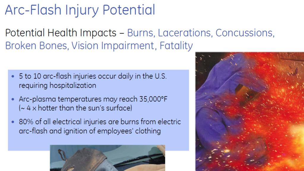
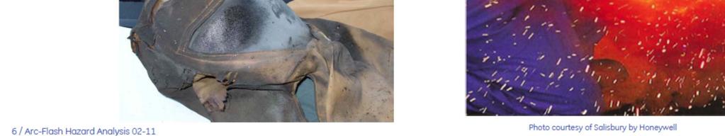
2 Electrical hazards Energized circuit/conductor Today s power system engineer must not only assure that the facility receives all the power it needs efficiently and reliably, it is also important to make sure it is done as safely as possible without loss of reliability and under tight budgetary constraints. Electric Shock* Approximately 30,000 nonfatal shock accidents occur each year. The National Safety Council estimates that about 1,000 fatalities each year are due to electrocution, more than half of them while servicing energized systems of less than 600 volts Arc Flash* When an electric current passes through air between ungrounded conductors, or between ungrounded conductors and grounded conductors, the temperatures can reach 35,000 F. Exposure to these extreme temperatures both burns the skin directly and causes ignition of clothing, which adds to the burn injury. The majority of hospital admissions due to electrical accidents are from arc-flash burns, not from shocks. Each year more than 2,000 people are admitted to burn centers with severe arc-flash burns. Arc-flashes can and do kill at distances of 10ft (3m). Arc Blast* The tremendous temperatures of the arc cause the explosive expansion of both the surrounding air and the metal in the arc path. For example, copper expands by a factor of 67,000 times when it turns from a solid to a vapor. The danger associated with this expansion is one of high pressures, sound, and shrapnel. The high pressures can easily exceed hundreds or even thousands of pounds per square foot, knocking workers off ladders, rupturing ear drums, and collapsing lungs. The sounds associated with these pressures can exceed 160dB. Finally, material and molten metal is expelled away from the arc at speeds exceeding 700 mph (1600 km/hr), fast enough for shrapnel to completely penetrate the human body. * - Definitions are reproduced with permision from NFPA70E Handbook for Electrical Safety in the Workplace, Copyright 2009, National Fire Protection Association. Being near live electrical equipment is dangerous, whether shock or arc flash hazard, solutions exist to reduce hazard risk levels in a wide range of conditions and needs.
3 Example of an Arc Flash Event 635V/65kA 12 Cycle event, door open 33 cal/cm 2

4 BOTTOM LINE: 4 GE Title or job number 03/21/2014
5

6 Problem scope 1 8 Arc flash explosions per day 1-2 $16M Deaths per day related to arc flash incidents Average costs for each arc flash incident At this cost, why take chances? 1. U.S. statistic cited by CapSchell, Inc. in a study for the Electric Power Research Institute, 1999
7 Arc Flash Hazard Overview Voltage Av ailable Short Circuit Current Source Enclosure Working Distance Heat Measurement Arc Flash energy is a function of: Time to clear Arcing current RMS & peak magnitude, & time Electrode Gap Voltage Available short circuit current Working distance Arc gap Arcing fault clearing time (not short circuit clearing time) Sensitivity of Breaker/Trip Unit Fixed Based on system design and source Arms are only so long Determined by equipment type A function of the protective device acting upon the arcing current Clearing time is the only parameter than can be modified after the power system design is set. Therefore. Arcing fault clearing TIME becomes the critical factor
8 Arcing current (I a ) variability IEEE 1584 & NFPA 70E provide good guidelines... But real world variability may not be fully considered Tripping device response is dependent on arcing current Arcing current is dependent on: Gap, Voltage & I bf 45 The variables include: Utility information (worst case v installed), cable length, temperature, joint & device Z, transformer Z, etc Ia 100% I a, 32 mm gap 85% I a, 40 mm gap Ibf


9 Arc flash protection PPE vs. cal/cm2 Many systems are > 12 cal/cm2: Generally uncomfortable and may impair dexterity Wearing suit could possibly cause accidents Getting the system <12 cal/cm2 can eliminate cumbersome PPE <12cal/cm2 >12cal/cm2
10 Incident energy dependant on event time Low level of incident energy requires fast mitigation. ~ ½ cycle interruption or less At the proper current level molded case CB & fuses operate in this range Large switchgear CB do not HRC-2 HRC Cal/cm Cal/Cm I bf cycle (large CB) clearing time (~50ms) 1.5 cycle A (MCCB) clearing time (~25ms) 0.5 cycle clearing time, or less, (~<8ms)
11 Multiple approaches for arc flash safety and downtime Approach Key Limitations Keep incident energy low Preventive maintenance activity protection Minimize event equipment damage Shield personnel / add distance Arc Transfer Protection System Some extra footprint considerations, LV only Fast Grounding Crowbar System Potential equipment damage due to high fault current Temporary Maint. Settings -RELT Unplanned exposures if not enabled Arc Resistant Equipment Retrofit, effluent vents, footprint considerations Current Limiting (CL) Circuit Breakers Fault current variability Fast (CL) Fuses Large bus protection can increase arc flash energy Faster/More Sensitive Circuit Breakers System reliability/ selectivity Remote Operation Costs & complexity Personnel Protective Equipment (PPE) Comfort & dexterity

12 Some Present Approaches


13 Containment method arc resistant Common in MV systems Moving into LV systems Contains arc inside structure Barrier between person & arc Must be fully assembled Plenum needed to exhaust May be solution for operators, but not for maintenance
14 Testing for Arc Resistance Conformance Testing (IEEE C ) performed with covers & doors secured Arc resistance rating based on door & covers being properly secured Testing done at prescribed voltage & current levels and presumes limited arc duration (0.5 sec recommended) but no standard set. Specified flammable cotton indicators are positioned to detect the escape of hazardous gases, plasma, etc. Pass/Fail Criteria - Door, covers, etc. do not open. Bowing/distortion is permitted except in panel used for relays, meters, etc. - No parts are ejected into the vertical plane defined by accessibility type - No openings caused by direct contact with an arc - No indicators ignite due to escaping gases or particles - All grounding connections remain effective
15 Other characteristics and alternatives Heavier sheet metal Double wall construction Space dedicated to internal flues to channel gasses External flue to channel gasses to outside environment Potential impact of overall size Potential impact on density of devices Arc resistant gear does not address the ability to operate switches, inspect meters and trouble shoot the equipment. Most of those same benefits may be achieved via remote controls, remote instrumentation and judicious use of digital communication and modern electronics.
16 Modern Circuit Breaker Technology Reduced Energy Let Thru or Maintenance Switch Flexible Time Current Curves to fit all your needs Advanced Instantaneous Algorithm ZSI (Zone Selective Interlock) now has Instantaneous Enables. Arc Flash Protection and Selectivity at the Same Time
17 Flexible Time Curves GTU Cu more precision in settings and tolerances ) Plugs: % sensor. LTPU % Plug Universal Rating Plugs 2) CB & Fuse Shaped LT Bands Seconds ) 22 LT delays in both CB & Fuse shapes, 44 total 4) STPU:1.5-12X LTPU, (0.05 increments) 5) STI 2 T slope: 3 different slopes sec ST PU 7 6 6) ST TB: As fast as 1.5 Cycles, 11 different bands, in 55ms increments 7) Instantaneous pickup 2X-15X standard, optional X Amperes 1,000 10, ,000
18 Examples of TU curve flexibility FUSE BREAKER


19 The Dilemma? Arcing Current is typically below traditional Selective/Coordinated Instantaneous Pickup What s more Important? Reliability/Selectivity Reduced Arc Flash Energy AF Energy Reduction Instantaneous Selectivity Reliability
20 Example Arc Flash Current Level Arc Flash is typically 35-55% of the Bolted Fault Level 42KAIC Available fault current = ~18kA to 21kA Arc Flash Current (based on IEEE 1584) 3000A Breaker with Instantaneous set to 7X or Above won t see the fault and will be tripping on Short Time or maybe even Long time. Why not set the Instantaneous to 4X or 5X? Selectivity compromised. Loose coordination with downstream equipment. Don t want the upstream device to trip if the fault is below a downstream device.
 1. Remember to turn ON and LOTO 2.")
21 A Popular Approach RELT Arc Flash Maintenance Safety Many other names However Switch EntelliGuard TU s RELT Switch With Positive Indication (Available on MCCB and ACB) 1. Remember to turn ON and LOTO 2. Turn it OFF: Uptime/Reliability is at stake
22 GTU Curve, CB1 & CB2 RELT TCC Seconds RELT OFF I-PU=45KAIC RELT ON I-PU=4.5KAIC Amperes 1,000 10, ,000 1,000,000
23 Now you can have Both, 24x7 Without the need for an ON/OFF Switch, Without sacrificing Reliability Trip unit algorithms monitor the current waveform to provide discriminant tripping Breaker to breaker communications HOW? Waveform Recognition Instantaneous Zone Selective Interlocking Instantaneous

24 Now you can have Both, 24x7 Without the need for an ON/OFF Switch, Without sacrificing Reliability HOW? OPTIMIZED INSTANTANEOUS SETTINGS Waveform Recognition Instantaneous Trip unit algorithms monitor the current waveform to provide discriminant tripping Zone Selective Interlocking Instantaneous Breaker to breaker communications
25 Waveform Recognition (WFR) Instantaneous 100,000 80,000 60,000 40,000 Prospective fault current (I bf ) Without WFR Instantaneous set above max peak let thru of downstream device (peak sensing) CL MCCB MCP FUSE x x 20, (20,000) (40,000) (60,000) (80,000) Amperes Seconds TU Set below Current Limiting peak let thru Instantaneous set below Arcing Current while maintaining selectivity.
26 GTU Curve, CB1 & CB2 Instantaneous Selectivity TU selective settings based on the curve of the downstream current limiting molded case CB. Depends on the MCCB curve being defined correctly Seconds 1.00 Minimum selective IPU setting Transition Amperes 1,000 10, ,000 1,000,000 1,000 10, ,000
27 Larger motor circuit protector 250A MCP 100,000 Peak Let-Through (I pk) 10,000 Feeder TU with Setting using WFR 1, Feeder TU with Setting using peak Arcing current 1,000 10, ,000 Fault Current (I bf ) 50 ka Ibf ~ ka Ia Feeding a 250A MCP or CB in MCC with: > peak sensing trip, pickup overlaps arcing current so setting does not provide reliable instantaneous arcing fault protection > waveform recognition (WFR) capability, provides selectivity & instantaneous arcing fault protection with ~10kA of margin
28 Zone Selective Interlocking (ZSI) Trip Trip ZSI blocking signal > Zone Selective Interlocking used to force upstream CB to be selective with downstream CB > When upstream CB receives signal that CB below is interrupting fault it operates at a restrained slower speed allowing downstream CB to clear > All manufacturers offer ST & G > Can only be applied when using LVPCB upstream. > 1000 ft. Max signal cable length.

29 What about next level up? I-ZSI Fault below feeder shifts Main curve to restrained At every level there is instantaneous protection 100% selective to 65kA and 85kA 1.00 x Seconds Seconds ,000 Amperes 10, , ,000 Amperes 10, ,000


30 Feeder Fault using Waveform Recognition and Instantaneous ZSI HRC 1 HRC 2 30 GE Title or job number 03/21/2014


31 LV system: <= 8 Cal/CM 2 on a 100KA I BF 480V MV Switchgear * 52 LV Switchgear * * * * * WFR - I MCC/Switchboard * ZSI - I * * * * Any Size 400A 1200A < 600A
32 A new approach What if a product could contain an arc fault in less than 8ms? a product could limit incident energy to 1.2 cal/cm 2? this could be done with equipment doors open? this could be done without adding additional bolted-fault type stress to the system? the product could be retrofit onto existing equipment?
33 Overview of arc containment method Arc Vault TM How it works


34 Alternative to Arc Resistance via containment - diversion Transfer to alternate current path 52 MV Breaker Present Technology - Crowbar > Remove arcing fault via bolted fault > Maximum bolted fault current > Electrical equipment damage XFMR Main LV Breaker Feeders..... New Technology Arc Containment Arc-to-arc transfer keeps energy low & allows fast mitigation Other equipment not damaged Fault eliminated in < ½ cycle No moving parts And, in new gear, meet the same Arc Resistance standard
35 Detection upstream controllable device MV Breaker XFMR Main Bus CT 52 Main LV Breaker Relay Entire switchgear line-up protected Incoming bus, main breaker, main bus, feeders Consider CT sensor placement Reasonable close-coupling Retrofit or new construction Arc Device Using transfer tripping & other techniques upstream protectors may be added as back up
36 Arc containment system Principle follows crowbar concept but.. Suppresses arc-flash with lower contained arc impedance Easier circuit interruption 63% less energy than a bolted fault Less impact on other components in electrical system Faster, simplified triggering method Fast transfer No moving parts Multiple use Maintenance tests


37 Arc containment device Outer Cover Isolation container Shock shield Arc created in interior chamber Vents Device has 3 functions Containment Isolation Dissipation Size = 2000A CB Electrode Plasma Gun Minimal venting Energy is dissipated/absorbed
38 Stress on power delivery system minimized I Z sys V sys Z capture sin Rt L wt e sin Open Air Arc Arc Containment Device 300 Crow Bar ka RMS ka Peak A^2S(1,000,000) Arc impedance is key Not 0 ohms Resistive reduces DC offset I peak related to mechanical damage 40% less than bolted I 2 t related to thermal damage 63% less than bolted
39 Arc transfer principles V capture V sys Z arc Z arc Z source Path of least impedance Impedance of new arc lower than fault arc being removed But NOT zero impedance Introduced arc must be stable & divert current long enough for upstream CB to interrupt Pressure & heat must be predictable & controllable

40 Triggering Dielectric reduction with plasma B ph A ph C ph Plasma gun breaks down air allowing current to flow between electrodes <200 microsecond pulse is required Spacing & electrode geometry prevent breakdown during normal operation Limited wear allows testing & triggering system reuse
41 Trigger arc No moving parts Microsecond duration Microsecond response Multiple use Low energy trigger source Field testable


42 Limit energy and protect equipment Instead of containing arc flash event in the equipment; limit energy from arc flash event Decreased arc energy and increased system reliability 3 cycle CB interruption Arc Vault TM protection


43 Arc Vault components and indicators Device Status / Activation Switch Containment Dome D/O mechanism like circuit breaker Stored Energy health monitor D/O mechanism like circuit breaker

44 The Arc Transfer Protection System: Will contain an arc fault in less than 8ms, resulting in incident energy in accordance with IEEE 1584 at 18 from the arc event of less than 1.2 cal/cm², with the circuit breaker compartment doors open, in a 480V 65kAIC system. Can be retrofit onto existing LV equipment, including switchgear, switchboards, and MCCs Reduces building construction costs because it does not require exhaust chimneys or plenums Can be returned to service within a working day in the event of an arc flash incident, which improves overall system uptime Reduces energy released by 63%, compared to crow-bar type systems, which will lessen stresses on other system components, and improves overall system uptime
45 Summary of A-F Mitigation Alternates MV Breaker 52 F35 Relay Mains Feeders MV Fused Switch Technical Approach Incident Energy Incident Energy XFMR Existing System ~200 cal ~170 cal MV CB w/ F35 Relay ~10 cal Good ~10 cal Good TU w/ izsi ~200 cal ~5 cal Good ETU Main LV Breaker Arc Vault TU w/ izsi & MV CB ~10 cal Better ~5 cal Better Arc Transfer with MV CB ~1 cal Best ~1 cal Best Feeders..... Values shown are for a typical 13.8kV to 480Volt Substation with 2500 kva transformer, 65 KA.


46 Electrically Operated Remote Racking Device for Low Voltage Switchgear The electrically operated racking device allows maintenance personnel the ability to be up to 30 feet away from a draw-out breaker during the racking operation.


47 REMOTE OPEN/CLOSE and MONITORING - Near gear HMI in a stand-alone or wall mount unit can be placed well beyond the arc flash boundary. - HMI interface installed on a remote desktop or laptop PC connected via a LAN or the Web.

48 Thank you.
Cause, Effect & Mitigation Strategies
 WSU HANDS ON RELAY SCHOOL 2019 Arc Flash Fault Cause, Effect & Mitigation Strategies Joe Xavier, Technical Manager West Region Arc Flash Fault - Agenda What is an Arc Flash? Why and when does Arc Flash
{40C54206-A3BA D8-8D8CF }
 Informative Annex D Incident Energy and Arc Flash Boundary Calculation Methods This informative annex is not a part of the requirements of this NFPA document but is included for informational purposes
ARC FLASH PPE GUIDELINES FOR INDUSTRIAL POWER SYSTEMS
 The Electrical Power Engineers Qual-Tech Engineers, Inc. 201 Johnson Road Building #1 Suite 203 Houston, PA 15342-1300 Phone 724-873-9275 Fax 724-873-8910 www.qualtecheng.com ARC FLASH PPE GUIDELINES FOR
Electrical Arc Hazards
 Arc Flash Analysis 1996-2009 ETAP Workshop Operation Notes Technology, 1996-2009 Inc. Operation Workshop Technology, Notes: Arc Inc. Flash Analysis Slide 1 Electrical Arc Hazards Electrical Arcs can occur
First Draft Language
 110.16 First Draft Language (B) Service Equipment. In addition to the requirements in (A), service equipment shall contain the following information: (1) Nominal system voltage (2) Arc flash boundary (3)
COMMON SOURCES OF ARC FLASH HAZARD IN INDUSTRIAL POWER SYSTEMS
 COMMON SOURCES OF ARC FLASH HAZARD IN INDUSTRIAL POWER SYSTEMS Joost Vrielink Hans Picard Wilbert Witteman Eaton Eaton SABIC-IP Europalaan 202 7559 SC Hengelo Europalaan 202 7559 SC Hengelo Plasticslaan
THREE PHASE PAD MOUNTED DISTRIBUTION TRANSFORMER ARC FLASH TESTING JUNE 23, 2009 FERRAZ SHAWMUT HIGH POWER LABORATORY NEWBURYPORT, MA
 THREE PHASE PAD MOUNTED DISTRIBUTION TRANSFORMER ARC FLASH TESTING JUNE 23, 2009 FERRAZ SHAWMUT HIGH POWER LABORATORY NEWBURYPORT, MA Witnessed by: Jim Phillips, PE, Consultant Craig DeRouen, ERMCO Director
NFPA-70E. Electrical Safety in the Workplace. Standard for Edition
 NFPA-70E Standard for Electrical Safety in the Workplace 2015 Edition NFPA-70E 90.1 Purpose. The purpose of this standard is to provide a practical safe working area for employees relative to the hazards
Standards for MV switchgear rated for arc flash protection
 Standards for MV switchgear rated for arc flash protection by Bryan Johnson, ABB Switchgear standards historically considered the electrical capability of switchgear with little regard to the effects of
Arc Flash Hazard and Mitigation 2 nd Workshop on Power Converters for Particle Accelerators June 14 16, 2010
 Arc Flash Hazard and Mitigation 2 nd Workshop on Power Converters for Particle Accelerators June 14 16, 2010 Paul Bellomo June 14-16, 2010 2nd Workshop on Power Converters for Particle Accelerators - Arc
1960 Research Drive, Suite 100, Troy, Michigan with. REVISION: December 10, 2007 (Supersedes previous versions) Prepared by:
 Prepared by:") ENGINEERING SERVICES 1960 Research Drive, Suite 100, Troy, Michigan 48083 ARC FLASH REDUCTION with SEPAM RELAY ZONE SELECTIVE INTERLOCKING REVISION: December 10, 2007 (Supersedes previous versions) Prepared
ENGINEERING SERVICES 1960 Research Drive, Suite 100, Troy, Michigan 48083 ARC FLASH REDUCTION with SEPAM RELAY ZONE SELECTIVE INTERLOCKING REVISION: December 10, 2007 (Supersedes previous versions) Prepared
Steve Kovach District Sales Engineer
 Steve Kovach District Sales Engineer 630-740-7463 Steveekovach@Eaton.com Institute of Electrical and Electronics Engineers American Society of Safety Engineers 1 Electrical Hazards Electrical Hazards Shock
AN EXAMPLE OF A STANDARD ARC FLASH PPE LABELING STRATEGY
 The Electrical Power Engineers Qual-Tech Engineers, Inc. 201 Johnson Road Building #1 Suite 203 Houston, PA 15342-1300 Phone 724-873-9275 Fax 724-873-8910 www.qualtecheng.com AN EXAMPLE OF A STANDARD ARC
Webinar: An Effective Arc Flash Safety Program
 Webinar: An Effective Arc Flash Safety Program Daleep Mohla September 10 th, 2015: 2pm ET Agenda Arc Flash Defined and Quantified NFPA 70E / CSA Z 462 - Recent Updates What is the ANSI Z10 Hierarchy of
Arc Flash Analysis and Documentation SOP
 Arc Flash Analysis and Documentation SOP I. Purpose.... 2 II. Roles & Responsibilities.... 2 A. Facilities Maintenance (FM).... 2 B. Zone Supervisors/ Shop Foremen... 2 C. PMCS & CPC... 2 III. Procedures...
Arc Flash Mitigation An Overview. Gus Nasrallah, P.E. Electroswitch May 30, 2013
 Arc Flash Mitigation An Overview Gus Nasrallah, P.E. Electroswitch May 30, 2013 Agenda Origin of Modern Arc Flash studies Why Now more than before NFPA 70E Standards Protection Zone IEEE 1584 2002 IEEE
ARC FLASH & PPE UPDATE. Michael Olivo, P.E. Aaron Ramirez, E.I.T.
 ARC FLASH & PPE UPDATE Michael Olivo, P.E. Aaron Ramirez, E.I.T. What is Arc Flash? Arc Flash is the release of heat and light produced when electrical current flows through an air gap between two conductors
Arc Flash Calculation Methods
 Arc Flash Calculation Methods Course No: E04-033 Credit: 4 PDH Velimir Lackovic, Char. Eng. Continuing Education and Development, Inc. 9 Greyridge Farm Court Stony Point, NY 10980 P: (877) 322-5800 F:
ARC FLASH HAZARD ANALYSIS AND MITIGATION
 ARC FLASH HAZARD ANALYSIS AND MITIGATION J.C. Das IEEE PRESS SERIES 0N POWER ENGINEERING Mohamed E. El-Hawary, Series Editor IEEE IEEE PRESS WILEY A JOHN WILEY & SONS, INC., PUBLICATION CONTENTS Foreword
AN EXAMPLE OF A STANDARD ARC FLASH PPE LABELING STRATEGY
 The Electrical Power Engineers Qual-Tech Engineers, Inc. 201 Johnson Road Building #1 Suite 203 Houston, PA 15342-1300 Phone 724-873-9275 Fax 724-873-8910 www.qualtecheng.com AN EXAMPLE OF A STANDARD ARC
STANDARDIZING ARC FLASH PPE LABELS
 The Electrical Power Engineers Qual-Tech Engineers, Inc. 01 Johnson Road Building #1 Suite 03 Houston, PA 1534-1300 Phone 74-873-975 Fax 74-873-8910 www.qualtecheng.com STANDARDIZING ARC FLASH PPE LABELS
Arc Flash and NFPA 70E
 Arc Flash and NFPA 70E Presented by: J.D. Kyle Safe Work Practices Wearing Proper PPE? OSHA 1910.333 (a) (1) not to work hot or live except : 1. De energizing introduces additional or increased hazards
Arc Flash Analysis Training
 Arc Flash Analysis Training Contact us Today for a FREE quotation to deliver this course at your company?s location. https://www.electricityforum.com/onsite-training-rfq An arc flash analysis study is
Protection Basics Presented by John S. Levine, P.E. Levine Lectronics and Lectric, Inc GE Consumer & Industrial Multilin
 Protection Basics Presented by John S. Levine, P.E. Levine Lectronics and Lectric, Inc. 770 565-1556 John@L-3.com 1 Protection Fundamentals By John Levine 2 Introductions Tools Outline Enervista Launchpad
A Guide to Establish an Arc Flash Safety Program for Electric Utilities
 A Guide to Establish an Arc Flash Safety Program for Electric Utilities by Craig Clarke, P.E. Eaton Corporation 50 Soccer Park Rd. Fenton, MO 63026 (636) 717-3406 CraigClarke@Eaton.com Ilanchezhian Balasubramanian,
APPLYING LOW-VOLTAGE CIRCUIT BREAKERS TO LIMIT ARC FLASH ENERGY
 APPLYING LOW-VOLTAGE CIRCUIT BREAKERS TO LIMIT ARC FLASH ENERGY Copyright Material IEEE Paper No. PCIC-2006-2 George Gregory Kevin J. Lippert Fellow Member, IEEE Senior Member, IEEE Schneider Electric
Key factors to maintaining arc flash safety
 APPLICATI TE Key factors to maintaining arc flash safety Arc flash and blast When an arc fault occurs, the result is a massive electrical explosion. The light and heat emitted by the explosion is known
Design Approaches for Hospital Distribution Systems With Considerations for Future Expansion, Operator Safety, and Cost
 Design Approaches for Hospital Distribution Systems With Considerations for Future Expansion, Operator Safety, and Cost Adam T. Powell, PE President Emerald Engineering, Inc. Jeffrey L. Small, Sr. Senior
SECTION OVERCURRENT PROTECTIVE DEVICE COORDINATION STUDY
 PART 1 - GENERAL 1.1 DESCRIPTION SECTION 26 05 73 OVERCURRENT PROTECTIVE DEVICE COORDINATION STUDY SPEC WRITER NOTE: Delete between // -- // if not applicable to project. Also, delete any other item or
2015 NFPA 70E. SESHA 2015 ARIZONA MINI CONFERENCE December 10, 2015 Intel Corporation
 2015 NFPA 70E SESHA 2015 ARIZONA MINI CONFERENCE December 10, 2015 Intel Corporation Introduction Jeffrey A. Pugh, P.E. Pugh Engineering LLC Bachelor of Science Degrees in Electrical Engineering and Computer
DESIGN STANDARD DS 29
 Assets Delivery Group Engineering DESIGN STANDARD DS 29 VERSION 1 REVISION 2 MAY 2018 FOREWORD The intent of Design Standards is to specify requirements that assure effective design and delivery of fit
3Ø Short-Circuit Calculations
 3Ø Short-Circuit Calculations Why Short-Circuit Calculations Several sections of the National Electrical Code relate to proper overcurrent protection. Safe and reliable application of overcurrent protective
Power System Study for the Pebble #2 Lift Station Las Vegas, Nevada
 PQTSi Power System Study for the Pebble #2 Lift Station Las Vegas, Nevada Coordination Study and Arc Flash Analysis Power Quality Technical Services, Inc. 683 Scenic Tierra Ln. Henderson, NV 89015 Prepared
Short Circuit Current Calculations
 Introduction Several sections of the National Electrical Code relate to proper overcurrent protection. Safe and reliable application of overcurrent protective devices based on these sections mandate that
This section applies to the requirements for the performance of power system studies by both the Design Engineer and the Contractor.
 Basis of Design This section applies to the requirements for the performance of power system studies by both the Design Engineer and the Contractor. Background Information A Short Circuit and Coordination
Effective System Grounding
 Effective System Grounding By Andrew Cochran of I-Gard and John DeDad of DeDad Consulting The costs associated with losses stemming from ground faults are staggering. For example, over a seven year period,
Paul Dobrowsky Innovative Technology Services
 Significant Changes to NFPA 70E -2009 Edition Paul Dobrowsky Innovative Technology Services 2008 IEEE PCIC 1 Repeat Presentation This has been previously presented 2008 IEEE Electrical Safety Workshop
SECTION SHORT CIRCUIT, COMPONENT PROTECTION, FLASH HAZARD AND SELECTIVE COORDINATION STUDY
 SECTION 16075 - SHORT CIRCUIT, COMPONENT PROTECTION, FLASH HAZARD AND SELECTIVE COORDINATION STUDY PART 1 GENERAL 1.1 SUMMARY A. Section Includes: 1. Provide a short-circuit, component protection, flash
NOTICE ER Roland Flood Pumping Station Arc Flash Study
 NOTICE This document contains the expression of the professional opinion of SNC-Lavalin Inc. (SLI) as to the matters set out herein, using its professional judgment and reasonable care. It is to be read
CHANGEABILITY OF ARC FLASH PARAMETERS AND ITS IMPACT ON HAZARD MITIGATION IN LOW VOLTAGE POWER SYSTEMS
 CHANGEABILITY OF ARC FLASH PARAMETERS AND ITS IMPACT ON HAZARD MITIGATION IN LOW VOLTAGE POWER SYSTEMS by Abdeslem Kadri Bachelor of Engineering, Boumerdes University INELEC, 1996 A thesis presented to
A DUMMIES GUIDE TO GROUND FAULT PROTECTION
 A DUMMIES GUIDE TO GROUND FAULT PROTECTION A DUMMIES GUIDE TO GROUND FAULT PROTECTION What is Grounding? The term grounding is commonly used in the electrical industry to mean both equipment grounding
Arc Hazard Assessment for DC Applications in the Transit Industry
 Arc Hazard Assessment for DC Applications in the Transit Industry Kenneth S.Y. Cheng Kinectrics Inc. Toronto, Canada Stephen L. Cress Kinectrics Inc. Toronto, Canada Donald J. Minini Excalibur Associates,
2018 Consultant s Handbook Division 26 Electrical ARC Flash Hazard Analysis
 1 Summary 1.1 Provide a complete Arc Flash Hazard Analysis for the project indicated in the accompanying RFP. The Analysis may be performed: independent of the construction project in concert with the
Electrical Measurement Safety. Sponsored By:
 Electrical Measurement Safety Sponsored By: About the Viewer Panel Slides: Go to the Links tab at the top and click on the link to download the PDF of the slides If you re watching the archive version,
Selective Coordination for Emergency and Legally-Required Standby Power Distribution Systems
 Selective Coordination for Emergency and Legally-Required Standby Power Distribution Systems Presented for the IEEE Central TN Section / Music City Power Quality Group August 1, 2006 By Ed Larsen and Bill
PREFACE ********************************************************** IT IS NOT INTENDED THAT THESE STANDARDS BE COPIED AND USED AS A SPECIFICATION!
 PREFACE This publication has been prepared as a guide for Architectural and Engineering (A&E) firms in the preparation of documents for the design and construction of new structures and the remodeling
Distribution Feeder Principles
 Distribution Feeder Principles Distribution Feeder Principles Introduction Electrical distribution is the final stage in the delivery of electricity to end users. The distribution system s network carries
How to maximize reliability using an alternative distribution system for critical loads
 White Paper WP024001EN How to maximize reliability using an alternative distribution system for critical loads Executive summary The electric power industry has several different distribution topologies
high RESISTANCE GROUNDING SYSTEM the power to protect www. ElectricalPartManuals. com Instruction Manual C-102
 G e m i n i high RESISTANCE GROUNDING SYSTEM the power to protect Instruction Manual C-102 HIGH RESISTANCE GROUNDING SYSTEM Gemini is a unique, fail safe, all-in-one neutral grounding system, combining
DC ARC FLASH. THE IMPLICATIONS OF NFPA 70E 2012 ON BATTERY MAINTENANCE
 DC ARC FLASH. THE IMPLICATIONS OF NFPA 70E 2012 ON BATTERY MAINTENANCE William Cantor, P.E. TPI Exton, PA 19341 Phil Zakielarz TPI Exton, PA 19341 Mario Spina Verizon Wireless Uniontown, OH 44685 Abstract
7P Series - Surge Protection Device (SPD) Features 7P P P
 Features 7P P P") Features 7P.09.1.255.0100 7P.01.8.260.1025 7P.02.8.260.1025 SPD Type 1+2 Surge arrester range - single phase system / three phase system Surge arresters suitable in low-voltage applications in order to
Features 7P.09.1.255.0100 7P.01.8.260.1025 7P.02.8.260.1025 SPD Type 1+2 Surge arrester range - single phase system / three phase system Surge arresters suitable in low-voltage applications in order to
A controlled arc-flash, produced in a flashtube. Even though the energy level used is fairly low (85 joules), the low-impedance, low-inductance
, the low-impedance, low-inductance") An arc flash (also called a flashover), which is distinctly different from the arc blast, is part of an arc fault, a type of electrical explosion or discharge that results from a low-impedance connection
An arc flash (also called a flashover), which is distinctly different from the arc blast, is part of an arc fault, a type of electrical explosion or discharge that results from a low-impedance connection
Electrical Protection System Design and Operation
 ELEC9713 Industrial and Commercial Power Systems Electrical Protection System Design and Operation 1. Function of Electrical Protection Systems The three primary aims of overcurrent electrical protection
Education & Training
 Distribution System Operator Certificate This program provides you with a proficient working knowledge in modern electric power distribution systems. These four classes are designed to walk students through
Bus Protection Fundamentals
 Bus Protection Fundamentals Terrence Smith GE Grid Solutions 2017 Texas A&M Protective Relay Conference Bus Protection Requirements High bus fault currents due to large number of circuits connected: CT
WAVEFORM CORRECTOR (WAVEFORM CORRECTORS) REPLACES SURGE PROTECTION DEVICES (SPD) PREVIOUSLY KNOWN AS (TVSS)
 REPLACES SURGE PROTECTION DEVICES (SPD) PREVIOUSLY KNOWN AS (TVSS)") WAVEFORM CORRECTOR (WAVEFORM CORRECTORS) REPLACES SURGE PROTECTION DEVICES (SPD) PREVIOUSLY KNOWN AS (TVSS) 1 PART 1: GENERAL This section describes materials and installation requirements for low voltage
WAVEFORM CORRECTOR (WAVEFORM CORRECTORS) REPLACES SURGE PROTECTION DEVICES (SPD) PREVIOUSLY KNOWN AS (TVSS) 1 PART 1: GENERAL This section describes materials and installation requirements for low voltage
MV ELECTRICAL TRANSMISSION DESIGN AND CONSTRUCTION STANDARD. PART 1: GENERAL 1.01 Transformer
 PART 1: GENERAL 1.01 Transformer A. This section includes liquid filled, pad mounted distribution transformers with primary voltage of 12kV or 4.16kV (The University will determine primary voltage), with
SECTION POWER SYSTEMS STUDIES
 PART 1 - GENERAL 1.1 RELATED SECTIONS: Refer to Division 15 for Mechanical requirements. Refer to Division 16 for Electrical requirements. 1.2 OBJECTIVE: A. The short-circuit study is to calculate the
Distribution/Substation Transformer
 Distribution/Substation Transformer Type VFI, Vacuum Fault Interrupter Transformer Option Functional Specification Guide Functional specification for 15 kv, 25 kv, or 35 kv vacuum fault interrupter distribution/substation
ADDENDUM NO. 2 PROJECT: COURTLAND PUMP STATION CONTRACT: IFB NO COM.00030
 ADDENDUM NO. 2 PROJECT: COURTLAND PUMP STATION CONTRACT: IFB NO. 2018-008-COM.00030 To: Prospective Bidders of Record Date: December 17, 2018 The following changes, additions, revisions, and/or deletions
NATIONAL ELECTRIC SAFETY CODE 2012 EDITION
 NATIONAL ELECTRIC SAFETY CODE (ANSI C2 / NESC) 2012 EDITION Jim Tomaseski IBEW Director of Safety and Health EEI Safety and Health Committee Conference NESC 2012 IMPORTANT DATES SEPTEMBER 1, 2009 - Preprint
Arc Flash Study Principles & Procedures for below 15 kv AC Systems. Xuan Wu, Dennis Hoffman, Ronald Wellman, and Manish Thakur
 Arc Flash Study Principles & Procedures for below 15 kv AC Systems Xuan Wu, Dennis Hoffman, Ronald Wellman, and Manish Thakur Agenda Arc Flash Study Purposes Introduction of Arc Flash Arc Flash Risk Locations
Arc Flash Hazard Standards:
 Arc Flash Hazard Standards: The Burning Question Presented by Sesha Prasad Specialist Power System Engineer Welcon Technologies At IDC Electrical Arc Flash Forum Melbourne April 14th & 15th 2010. Session
CHAPTER 15 GROUNDING REQUIREMENTS FOR ELECTRICAL EQUIPMENT
 CHAPTER 15 GROUNDING REQUIREMENTS FOR ELECTRICAL EQUIPMENT A. General In a hazardous location grounding of an electrical power system and bonding of enclosures of circuits and electrical equipment in the
Practical Experience in On-Line Partial Discharge Measurements of MV Switchgear Systems
 Practical Experience in On-Line Partial Discharge Measurements of MV Switchgear Systems Z. Berler, I. Blokhintsev, A. Golubev, G. Paoletti, V. Rashkes, A. Romashkov Cutler-Hammer Predictive Diagnostics
7. INSPECTION AND TEST PROCEDURES
 7.1 Switchgear and Switchboard Assemblies A. Visual and Mechanical Inspection 1. Compare equipment nameplate data with drawings and specifications. 2. Inspect physical and mechanical condition. 3. Inspect
Technical T TECHNICAL. C o n t e n t s SPEEDFAX TM 2017
 SPEEDFAX TM 2017 TSection C o n t e n t s Types of Power Distribution Systems T-2 T-4 Ground Fault Protection T-5 T-10 Overcurrent Protection and Coordination T-11 System Analysis T-12 Current Limiting
Grounding Recommendations for On Site Power Systems
 Grounding Recommendations for On Site Power Systems Revised: February 23, 2017 2017 Cummins All Rights Reserved Course Objectives Participants will be able to: Explain grounding best practices and code
Ampgard The name motor applications rely on
 Medium-voltage motor control The name motor applications rely on Oil and gas Mining Water/wastewater Pulp and paper Utility A legacy of reliability for more than 4 decades 1950 1960 1970 1980* 1990 2000
GE Multilin technical note
 GE Digital Energy Multilin GE Multilin technical note GE Multilin releases fast and dependable short circuit protection enhanced for performance under CT saturation GE publication number: GER-4329 GE Multilin
Electrical Safety Policy Health and Safety FCX-HS03 Release 07/2018 Version 1
 Electrical Safety Policy Health and Safety FCX-HS03 Release 07/2018 Version 1 POTENTIAL FATAL RISKS Exposure to Electrical Hazards CRITICAL CONTROLS Access Control Barriers and Segregation Electrical PPE
REDUCING ARC FLASH HAZARD BY REMOTE SWITCHING
 The Electrical Power Engineers Qual-Tech Engineers, Inc. 21 Johnson Road Building #1 Suite 23 Houston, PA 15342-13 Phone 724-873-9275 Fax 724-873-891 www.qualtecheng.com REDUCING ARC FLASH HAZARD BY REMOTE
The Importance of the Neutral-Grounding Resistor. Presented by: Jeff Glenney, P.Eng. and Don Selkirk, E.I.T.
 The Importance of the Neutral-Grounding Resistor Presented by: Jeff Glenney, P.Eng. and Don Selkirk, E.I.T. Presentation Preview What is high-resistance grounding (HRG)? What is the purpose of HRG? Why
NERC Protection Coordination Webinar Series June 16, Phil Tatro Jon Gardell
 Power Plant and Transmission System Protection Coordination Phase Distance (21) and Voltage-Controlled or Voltage-Restrained Overcurrent Protection (51V) NERC Protection Coordination Webinar Series June
1 INTRODUCTION 1.1 PRODUCT DESCRIPTION
 GEK-00682D INTRODUCTION INTRODUCTION. PRODUCT DESCRIPTION The MDP Digital Time Overcurrent Relay is a digital, microprocessor based, nondirectional overcurrent relay that protects against phase-to-phase
GE Ventilated Dry-Type Transformers. Secondary Substation Transformers - 5 and 15kV Class
 GE Ventilated Dry-Type Transformers Secondary Substation Transformers - 5 and 15kV Class GE ventilated dry-type transformers are designed for indoor or outdoor applications in schools, hospitals, industrial
1% Switchgear and Substations
 1% Switchgear and Substations Switchgear and substations are not always matters of concern for transmitter designers, -because they are often part of the facilities of a typical installation. However,
Arc Flash Hazard. Can HRG Technology play a role in prevention?
 Arc Flash Hazard Can HRG Technology play a role in prevention? Although arc hazards have existed since man began using electricity, increasing deaths, injuries and property loss from arcing faults have
Thomas Wilkins Wilkins Consulting Henderson Nevada U.S.A.
 Medium Voltage Vacuum Circuit Breaker with Mechanically Interlocked Grounding Switch (VDH/GSMI) Provides Better Safety and Reliability for Wind and Solar Power Plants and Their Personnel than Remote Transfer
High Voltage Testing. Team 5: Justin Bauer, Matt Clary, Zongheng Pu, DeAndre Dawson, Adam McHale
 High Voltage Testing Team 5: Justin Bauer, Matt Clary, Zongheng Pu, DeAndre Dawson, Adam McHale Presentation Content Introduction Basics Defining High Voltage Risk Factors Safety Issues with High Voltage
Addendum to Instructions for Installation, Operation and Maintenance of Digitrip 3000 Protective Relays
 Dual-Source Power Supply Addendum to I.B. 17555 Addendum to Instructions for Installation, Operation and Maintenance of Digitrip 3000 Protective Relays Table of Contents Page 1.0 Introduction...1 2.0 General
Variable Frequency Drive Packages with Harmonic Mitigation. Low Harmonic Drive Packages Engineered by Rockwell Automation
 Variable Frequency Drive Packages with Harmonic Mitigation Low Harmonic Drive Packages Engineered by Rockwell Automation What Do I Need to know About Harmonics? What are Harmonics? Harmonics are deviations
Overview of Grounding for Industrial and Commercial Power Systems Presented By Robert Schuerger, P.E.
 Overview of Grounding for Industrial and Commercial Power Systems Presented By Robert Schuerger, P.E. HP Critical Facility Services delivered by EYP MCF What is VOLTAGE? Difference of Electric Potential
Topic 6 Quiz, February 2017 Impedance and Fault Current Calculations For Radial Systems TLC ONLY!!!!! DUE DATE FOR TLC- February 14, 2017
 Topic 6 Quiz, February 2017 Impedance and Fault Current Calculations For Radial Systems TLC ONLY!!!!! DUE DATE FOR TLC- February 14, 2017 NAME: LOCATION: 1. The primitive self-inductance per foot of length
CREATING A COMPARATIVE MAP OF RELATIVE POWER FOR DC ARC FLASH METHODOLOGIES. A Thesis. presented to
 CREATING A COMPARATIVE MAP OF RELATIVE POWER FOR DC ARC FLASH METHODOLOGIES A Thesis presented to the Faculty of California Polytechnic State University, San Luis Obispo In Partial Fulfillment of the Requirements
PRACTICAL PROBLEMS WITH SUBSTATION EARTHING
 1 PRACTICAL PROBLEMS WITH SUBSTATION EARTHING Dr Hendri Geldenhuys Craig Clark Eskom Distribution Technology This paper considers the issues around substation sites where the soil resistivity is of particularly
APQline Active Harmonic Filters. N52 W13670 NORTHPARK DR. MENOMONEE FALLS, WI P. (262) F. (262)
 F. (262)") APQline Active Harmonic Filters N52 W13670 NORTHPARK DR. MENOMONEE FALLS, WI 53051 P. (262) 754-3883 F. (262) 754-3993 www.apqpower.com Power electronic equipment and AC-DC power conversion equipment contribute
APQline Active Harmonic Filters N52 W13670 NORTHPARK DR. MENOMONEE FALLS, WI 53051 P. (262) 754-3883 F. (262) 754-3993 www.apqpower.com Power electronic equipment and AC-DC power conversion equipment contribute
SDCS-03 DISTRIBUTION NETWORK GROUNDING CONSTRUCTION STANDARD (PART-I) UNDERGROUND NETWORK GROUNDING. Rev. 01
 UNDERGROUND NETWORK GROUNDING. Rev. 01") SDCS-03 DISTRIBUTION NETWORK GROUNDING CONSTRUCTION STANDARD (PART-I) UNDERGROUND NETWORK GROUNDING Rev. 01 This specification is property of SEC and subject to change or modification without any notice
SDCS-03 DISTRIBUTION NETWORK GROUNDING CONSTRUCTION STANDARD (PART-I) UNDERGROUND NETWORK GROUNDING Rev. 01 This specification is property of SEC and subject to change or modification without any notice
Best Practice Reducing The Risk of Arc Flash Cross Over
 Best Practice Reducing The Risk of Arc Flash Cross Over 1 2 Electrical Systems Are Critical 3 Why Do We Complete Electrical Maintenance Energized?? 4 Which Bulb Is Not Working?? 5 Functioning Correctly
MV network design & devices selection EXERCISE BOOK
 MV network design & devices selection EXERCISE BOOK EXERCISES 01 - MV substation architectures 02 - MV substation architectures 03 - Industrial C13-200 MV substation 04 - Max. distance between surge arrester
In order to minimise distribution (11 and 22 kv) feeder breaker
 feeder breaker") Lightning protection for equipment on MV feeders By WJD van Schalkwyk and M du Preez, Eskom This article presents the influence of lightning on MV feeders supplying small power users (400/230 V) with focus
Lightning protection for equipment on MV feeders By WJD van Schalkwyk and M du Preez, Eskom This article presents the influence of lightning on MV feeders supplying small power users (400/230 V) with focus
I P. /dt. di p V S Applications. Standards 1) IEC : 2007; IEC : ) IEC : 2016; IEC : 2017
 IEC : 2007; IEC : ) IEC : 2016; IEC : 2017") Ref: ART-B22-D70, ART-B22-D125, ART-B22-D175, ART-B22-D300 Flexible clip-around Rogowski coil for the electronic measurement of AC current with galvanic separation between the primary circuit (power) and
Ref: ART-B22-D70, ART-B22-D125, ART-B22-D175, ART-B22-D300 Flexible clip-around Rogowski coil for the electronic measurement of AC current with galvanic separation between the primary circuit (power) and
INSTRUCTION MANUAL. March 11, 2003, Revision 3
 INSTRUCTION MANUAL Model 701A Stimulator March 11, 2003, Revision 3 Copyright 2003 Aurora Scientific Inc. Aurora Scientific Inc. 360 Industrial Parkway S., Unit 4 Aurora, Ontario, Canada L4G 3V7 Tel: 1-905-727-5161
Protective Relays Digitrip 3000
 New Information Technical Data Effective: May 1999 Page 1 Applications Provides reliable 3-phase and ground overcurrent protection for all voltage levels. Primary feeder circuit protection Primary transformer
Earthing of Electrical Devices and Safety
 Earthing of Electrical Devices and Safety JOŽE PIHLER Faculty of Electrical Engineering and Computer Sciences University of Maribor Smetanova 17, 2000 Maribor SLOVENIA joze.pihler@um.si Abstract: - This
Industrial and Commercial Power Systems Topic 7 EARTHING
 The University of New South Wales School of Electrical Engineering and Telecommunications Industrial and Commercial Power Systems Topic 7 EARTHING 1 INTRODUCTION Advantages of earthing (grounding): Limitation
2017 ELECTRICAL SAFETY SERVICES. Arc Flash Electrical Maintenance Lockout/Tagout And More
 2017 ELECTRICAL SAFETY SERVICES Arc Flash Electrical Maintenance Lockout/Tagout And More ABOUT LEWELLYN TECHNOLOGY Improving workplace safety since 1993 Daryn Lewellyn founded Lewellyn Technology more
Reducing the Effects of Short Circuit Faults on Sensitive Loads in Distribution Systems
 Reducing the Effects of Short Circuit Faults on Sensitive Loads in Distribution Systems Alexander Apostolov AREVA T&D Automation I. INTRODUCTION The electric utilities industry is going through significant
Utility Interconnection and System Protection
 Utility Interconnection and System Protection Alex Steselboim President, Advanced Power Technologies, Inc. Utility paralleling vs. isolated operation. Isochronous kw load sharing Reactive power (VAR) sharing
POWER SYSTEM ANALYSIS TADP 641 SETTING OF OVERCURRENT RELAYS
 POWER SYSTEM ANALYSIS TADP 641 SETTING OF OVERCURRENT RELAYS Juan Manuel Gers, PhD Protection coordination principles Relay coordination is the process of selecting settings that will assure that the relays