Arc Flash and NFPA 70E
|
|
|
- Joshua May
- 5 years ago
- Views:
Transcription


1 Arc Flash and NFPA 70E Presented by: J.D. Kyle Safe Work Practices Wearing Proper PPE? OSHA (a) (1) not to work hot or live except : 1. De energizing introduces additional or increased hazards Emerg systems, Life Support. 2. Infeasible due to equipment design or operational limitations - troubleshooting 1

2 35,000 F Electrical Arc Molten Metal Pressure Waves Sound Waves Copper Vapor: Solid to Vapor Expands by 67,000 times Shrapnel Hot Air-Rapid Expansion Intense Light 2012 NFPA 70 E Responsibility Responsibility: The employer shall provide the safety related work practices and shall train the employee, who shall implement them 2
3 110.2 (A) Safety Training For employees who face electrical risk that has not been de-energized. Employees shall be trained to: Understand specific hazards associated with electrical energy Trained in safety related work practices Procedural requirements Trained to identify & understand relationship between electrical hazards and possible injury (D)(1) Qualified Person Qualified Person- Shall be trained and knowledgeable of the construction & operation of equipment or specific work method and be trained to recognize and avoid the electrical hazards that might be present with respect to that equipment or work method. 3
4 110.2 (D)(1) Qualified Person. Continued (a) Such persons shall also be familiar with the proper use of special precautionary techniques -PPE including arc flash suit -insulating and shielding material -insulated tools -and test equipment A person can be qualified with respect to certain equipment and methods but still be unqualified for others (D)(1) Qualified Person. Continued (b)(4) Decision-making process necessary to determine the degree and extend of the hazard and the ppe and job planning necessary to perform the task safely Note: Re-training shall be performed at intervals not to exceed 3 years 4
 Time (sec) (cycles) =Incident Energy=CAL/CM2 11 Cal FR vs.")
5 ARC Flash 3 Main Factors Determining an Arc Flash Available Energy (Ka) Distance (inches) Time (sec) (cycles) =Incident Energy=CAL/CM2 11 Cal FR vs. Std Cotton non FR 5

6 25 cal/cm2 suit vs. std non FR plus non FR denim = ~5 cal ARC FLASH ANALYSIS An arc flash hazard analysis shall determine the arc flash boundary, the incident energy at the working distance and the ppe people within the arc flash boundary shall use. Exception: The requirements of 130.7(c)(15) and 130.7(c)(16) shall be permitted in lieu of determining the incident energy at the working distance 6
7 Table 130.7(c)(16) Protective Clothing and PPE Hazard Risk Category Clothing (HRC) 0 Nonmelting flammable (untreated cotton, wool, rayon etc with a fabric weight of at least 4.5 oz 1 Arc-rated FR shirt and FR pants or coveralls 2 Arc rated FR shirt and FR pants or coveralls 3 Arc rated FRsystem to meets required minimum 4 Arcrated system meets required minimum Cal/cm2 Nonmelting clothing at least 4.5 oz Minimum Arc Rating of 4 Minimum arc rating of 8 Minimum Arc Rating of 25 Minimum Arc Rating of 40 7
8 Work Scope Install and verify Phase rotation on line side of a 480 Volt 60 amp Disconnect. Using tables determine level of ppe required D.5 Calculation of Incident Energy for an Arc Flash Analysis 8


9 Work Scope: Install & verify phase rotation on line side of a 480V, 60amp disconnect 480V 600A 13kv 480 V 1200A 480V 2500Kva 480V Utility Main Main, Transformer 600A 3 sec 3500A fuses Determine level of PPE to perform work? 480V 60A Disconnect 480V 600A Various software that can help you conduct an Arc Flash Analysis -Duke Flux calculator -Easy Power Calculator -Arc Advisor 9


10 Work Scope: Install & verify phase rotation on line side of a 480V, 60amp disconnect 480V 600A Utility 13kv 1200A Main 480 V Transformer 480V Main, 1200A 480V 600A A B What point has higher arc flash potential? A or B 480V 600A Incident Energy 10


11 Incident Energy Incident Energy 11


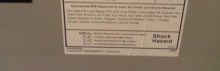
12 Incident Energy! 24 inch Flash Hazard Boundary 3 cal/cm 2 Flash Hazard at 18 inches 1 PPE Level, 1 Layer 6 oz Nomex, Leather Gloves Faceshield 480 VAC Shock Hazard when Cover is removed 36 inch Limited Approach 12 inch Restricted Approach V Class 00 Gloves 1 inch Prohibited Approach V Class 00 Gloves Equipment Name: Slurry Pump Starter Date: Courtesy E.I. du Pont de Nemours & Co. WARNING Arc Flash and Shock Hazard Appropriate PPE Required P25 Review the labels every 5 years or when changes or upgrades occur 12

13 Biggest cause of Death and Burns Human Error 98% 22.6 KA Symmetrical Available Fault 480V, 3 Phase 6 cycle STD 640A OCPD 6 cycle opening Non Current Limiting with Short Time Delay Test No. 4 Fault Initiated on Line Side of 30A Fuse 30A RK-1 Current Limiting Fuse Size 1 Starter 13

14 Arc Flash Sound ft. T2 >225 C / 437 F T3 50 C / 122 F Results: Test No P1 >2160 lbs/sq.ft T1 > 225 C / 437 F > Indicates Meter Pegged 14

15 22.6 KA Symmetrical Available Fault 480V, 3 Phase 601A. Class L Current Limiting Fuse This type of OCPD has a let through of 11KA and clears in ½ cycle Fault Initiated on Line Side of 30A Fuse Test No. 3 30A RK-1 Current Limiting Fuse Size 1 Starter Arc Flash 15
16 Results: Test No.3 = Sound ft. T2 62 C / F T3 P1 504 lbs/sq.ft T1 > 175 C / 347 F (No Change From Ambient) > Indicates Meter Pegged Biggest cause of Death and Burns Human Error 98% 16
17 TURN THE POWER OFF Work out ways to de energize Not the dinosaur method to work on or around it energized NO POWER = NO ARC FLASH or NO SHOCK This is the easiest, quickest and safest Challenge owners or contractors that push to do it energized 17
18
19
20
21
22
Steve Kovach District Sales Engineer
 Steve Kovach District Sales Engineer 630-740-7463 Steveekovach@Eaton.com Institute of Electrical and Electronics Engineers American Society of Safety Engineers 1 Electrical Hazards Electrical Hazards Shock
AN EXAMPLE OF A STANDARD ARC FLASH PPE LABELING STRATEGY
 The Electrical Power Engineers Qual-Tech Engineers, Inc. 201 Johnson Road Building #1 Suite 203 Houston, PA 15342-1300 Phone 724-873-9275 Fax 724-873-8910 www.qualtecheng.com AN EXAMPLE OF A STANDARD ARC
AN EXAMPLE OF A STANDARD ARC FLASH PPE LABELING STRATEGY
 The Electrical Power Engineers Qual-Tech Engineers, Inc. 201 Johnson Road Building #1 Suite 203 Houston, PA 15342-1300 Phone 724-873-9275 Fax 724-873-8910 www.qualtecheng.com AN EXAMPLE OF A STANDARD ARC
STANDARDIZING ARC FLASH PPE LABELS
 The Electrical Power Engineers Qual-Tech Engineers, Inc. 01 Johnson Road Building #1 Suite 03 Houston, PA 1534-1300 Phone 74-873-975 Fax 74-873-8910 www.qualtecheng.com STANDARDIZING ARC FLASH PPE LABELS
Electrical Arc Hazards
 Arc Flash Analysis 1996-2009 ETAP Workshop Operation Notes Technology, 1996-2009 Inc. Operation Workshop Technology, Notes: Arc Inc. Flash Analysis Slide 1 Electrical Arc Hazards Electrical Arcs can occur
2015 NFPA 70E. SESHA 2015 ARIZONA MINI CONFERENCE December 10, 2015 Intel Corporation
 2015 NFPA 70E SESHA 2015 ARIZONA MINI CONFERENCE December 10, 2015 Intel Corporation Introduction Jeffrey A. Pugh, P.E. Pugh Engineering LLC Bachelor of Science Degrees in Electrical Engineering and Computer
Paul Dobrowsky Innovative Technology Services
 Significant Changes to NFPA 70E -2009 Edition Paul Dobrowsky Innovative Technology Services 2008 IEEE PCIC 1 Repeat Presentation This has been previously presented 2008 IEEE Electrical Safety Workshop
NFPA-70E. Electrical Safety in the Workplace. Standard for Edition
 NFPA-70E Standard for Electrical Safety in the Workplace 2015 Edition NFPA-70E 90.1 Purpose. The purpose of this standard is to provide a practical safe working area for employees relative to the hazards
First Draft Language
 110.16 First Draft Language (B) Service Equipment. In addition to the requirements in (A), service equipment shall contain the following information: (1) Nominal system voltage (2) Arc flash boundary (3)
ARC FLASH & PPE UPDATE. Michael Olivo, P.E. Aaron Ramirez, E.I.T.
 ARC FLASH & PPE UPDATE Michael Olivo, P.E. Aaron Ramirez, E.I.T. What is Arc Flash? Arc Flash is the release of heat and light produced when electrical current flows through an air gap between two conductors
DC ARC FLASH. THE IMPLICATIONS OF NFPA 70E 2012 ON BATTERY MAINTENANCE
 DC ARC FLASH. THE IMPLICATIONS OF NFPA 70E 2012 ON BATTERY MAINTENANCE William Cantor, P.E. TPI Exton, PA 19341 Phil Zakielarz TPI Exton, PA 19341 Mario Spina Verizon Wireless Uniontown, OH 44685 Abstract
Arc Flash Mitigation An Overview. Gus Nasrallah, P.E. Electroswitch May 30, 2013
 Arc Flash Mitigation An Overview Gus Nasrallah, P.E. Electroswitch May 30, 2013 Agenda Origin of Modern Arc Flash studies Why Now more than before NFPA 70E Standards Protection Zone IEEE 1584 2002 IEEE
NATIONAL ELECTRIC SAFETY CODE 2012 EDITION
 NATIONAL ELECTRIC SAFETY CODE (ANSI C2 / NESC) 2012 EDITION Jim Tomaseski IBEW Director of Safety and Health EEI Safety and Health Committee Conference NESC 2012 IMPORTANT DATES SEPTEMBER 1, 2009 - Preprint
Electrical Safety Policy Health and Safety FCX-HS03 Release 07/2018 Version 1
 Electrical Safety Policy Health and Safety FCX-HS03 Release 07/2018 Version 1 POTENTIAL FATAL RISKS Exposure to Electrical Hazards CRITICAL CONTROLS Access Control Barriers and Segregation Electrical PPE
Key factors to maintaining arc flash safety
 APPLICATI TE Key factors to maintaining arc flash safety Arc flash and blast When an arc fault occurs, the result is a massive electrical explosion. The light and heat emitted by the explosion is known
Arc Flash Analysis and Documentation SOP
 Arc Flash Analysis and Documentation SOP I. Purpose.... 2 II. Roles & Responsibilities.... 2 A. Facilities Maintenance (FM).... 2 B. Zone Supervisors/ Shop Foremen... 2 C. PMCS & CPC... 2 III. Procedures...
Arc Flash Analysis Training
 Arc Flash Analysis Training Contact us Today for a FREE quotation to deliver this course at your company?s location. https://www.electricityforum.com/onsite-training-rfq An arc flash analysis study is
Selection of PPE Practical experience of different arc assessment methods and their comparison
 Selection of PPE Practical experience of different arc assessment methods and their comparison Dr.-Ing. Thomas Jordan Markus Kauschke Slide 1 ICOLIM 2017 Selection of Arc Flash PPE BSD Electrical Safety
2018 Consultant s Handbook Division 26 Electrical ARC Flash Hazard Analysis
 1 Summary 1.1 Provide a complete Arc Flash Hazard Analysis for the project indicated in the accompanying RFP. The Analysis may be performed: independent of the construction project in concert with the
Arc Flash Hazard and Mitigation 2 nd Workshop on Power Converters for Particle Accelerators June 14 16, 2010
 Arc Flash Hazard and Mitigation 2 nd Workshop on Power Converters for Particle Accelerators June 14 16, 2010 Paul Bellomo June 14-16, 2010 2nd Workshop on Power Converters for Particle Accelerators - Arc
THREE PHASE PAD MOUNTED DISTRIBUTION TRANSFORMER ARC FLASH TESTING JUNE 23, 2009 FERRAZ SHAWMUT HIGH POWER LABORATORY NEWBURYPORT, MA
 THREE PHASE PAD MOUNTED DISTRIBUTION TRANSFORMER ARC FLASH TESTING JUNE 23, 2009 FERRAZ SHAWMUT HIGH POWER LABORATORY NEWBURYPORT, MA Witnessed by: Jim Phillips, PE, Consultant Craig DeRouen, ERMCO Director
Arc Flash Calculation Methods
 Arc Flash Calculation Methods Course No: E04-033 Credit: 4 PDH Velimir Lackovic, Char. Eng. Continuing Education and Development, Inc. 9 Greyridge Farm Court Stony Point, NY 10980 P: (877) 322-5800 F:
Arc Flash Hazard Standards:
 Arc Flash Hazard Standards: The Burning Question Presented by Sesha Prasad Specialist Power System Engineer Welcon Technologies At IDC Electrical Arc Flash Forum Melbourne April 14th & 15th 2010. Session
NOTICE ER Roland Flood Pumping Station Arc Flash Study
 NOTICE This document contains the expression of the professional opinion of SNC-Lavalin Inc. (SLI) as to the matters set out herein, using its professional judgment and reasonable care. It is to be read
A Guide to Establish an Arc Flash Safety Program for Electric Utilities
 A Guide to Establish an Arc Flash Safety Program for Electric Utilities by Craig Clarke, P.E. Eaton Corporation 50 Soccer Park Rd. Fenton, MO 63026 (636) 717-3406 CraigClarke@Eaton.com Ilanchezhian Balasubramanian,
NORTHWEST FLORIDA STATE COLLEGE MONUMENT SIGNS WITH LED DISPLAYS
 PREPARED FOR: FOUNDATION PLAN & STRUCTURAL NOTES DESIGNED BY: NJB DRAWN BY: NJB REVIEWED BY: BLSE S1 PREPARED FOR: FRAMING PLANS DESIGNED BY: NJB DRAWN BY: NJB REVIEWED BY: BLSE S2 PREPARED FOR: SECTION
How does an Arc occur?
 Contact us = sales@liveline.co.za How does an Arc occur? Arc Flash Suits are designed to provide protection from arc flash heat exposures. Arc flash suits are designed to protect the electrical technician
How does an Arc occur?
 How does an Arc occur? Arc Flash Suits are designed to provide protection from arc flash heat exposures. Arc flash suits are designed to protect the electrical technician from heat and to reduce or minimize
Electrical Measurement Safety. Sponsored By:
 Electrical Measurement Safety Sponsored By: About the Viewer Panel Slides: Go to the Links tab at the top and click on the link to download the PDF of the slides If you re watching the archive version,
Education & Training
 Distribution System Operator Certificate This program provides you with a proficient working knowledge in modern electric power distribution systems. These four classes are designed to walk students through
Webinar: An Effective Arc Flash Safety Program
 Webinar: An Effective Arc Flash Safety Program Daleep Mohla September 10 th, 2015: 2pm ET Agenda Arc Flash Defined and Quantified NFPA 70E / CSA Z 462 - Recent Updates What is the ANSI Z10 Hierarchy of
REDUCING ARC FLASH HAZARD BY REMOTE SWITCHING
 The Electrical Power Engineers Qual-Tech Engineers, Inc. 21 Johnson Road Building #1 Suite 23 Houston, PA 15342-13 Phone 724-873-9275 Fax 724-873-891 www.qualtecheng.com REDUCING ARC FLASH HAZARD BY REMOTE
ADDENDUM NO. 2 PROJECT: COURTLAND PUMP STATION CONTRACT: IFB NO COM.00030
 ADDENDUM NO. 2 PROJECT: COURTLAND PUMP STATION CONTRACT: IFB NO. 2018-008-COM.00030 To: Prospective Bidders of Record Date: December 17, 2018 The following changes, additions, revisions, and/or deletions
Arc Flash Study Principles & Procedures for below 15 kv AC Systems. Xuan Wu, Dennis Hoffman, Ronald Wellman, and Manish Thakur
 Arc Flash Study Principles & Procedures for below 15 kv AC Systems Xuan Wu, Dennis Hoffman, Ronald Wellman, and Manish Thakur Agenda Arc Flash Study Purposes Introduction of Arc Flash Arc Flash Risk Locations
The advantages of transformers. EMC-ESD in de praktijk Jan-Kees van der Ven
 The advantages of transformers EMC-ESD in de praktijk 09-11-2016 Jan-Kees van der Ven Introduction RH Marine Additional benefits Common mode reduction LF Harmonic reduction Common mode reduction HF Fault
ARC FLASH PPE GUIDELINES FOR INDUSTRIAL POWER SYSTEMS
 The Electrical Power Engineers Qual-Tech Engineers, Inc. 201 Johnson Road Building #1 Suite 203 Houston, PA 15342-1300 Phone 724-873-9275 Fax 724-873-8910 www.qualtecheng.com ARC FLASH PPE GUIDELINES FOR
Cause, Effect & Mitigation Strategies
 WSU HANDS ON RELAY SCHOOL 2019 Arc Flash Fault Cause, Effect & Mitigation Strategies Joe Xavier, Technical Manager West Region Arc Flash Fault - Agenda What is an Arc Flash? Why and when does Arc Flash
SECTION SHORT CIRCUIT, COMPONENT PROTECTION, FLASH HAZARD AND SELECTIVE COORDINATION STUDY
 SECTION 16075 - SHORT CIRCUIT, COMPONENT PROTECTION, FLASH HAZARD AND SELECTIVE COORDINATION STUDY PART 1 GENERAL 1.1 SUMMARY A. Section Includes: 1. Provide a short-circuit, component protection, flash
Electrical Severity Measurement Tool Revision 4
 Electrical Severity Measurement Tool Revision 4 November 2017 Electrical Severity Measurement Tool 1.0 Purpose: This tool is intended to measure the severity of exposure to an electrical safety event based
Copper Core & Coil Transformer
 Copper Core & Coil Transformer Transformer Stomach Pain Normal Operation: Transformer internal structures and windings are subjected to mechanical forces due to the magnetic forces. Through fault current
Short Circuit Current Calculations
 Introduction Several sections of the National Electrical Code relate to proper overcurrent protection. Safe and reliable application of overcurrent protective devices based on these sections mandate that
3Ø Short-Circuit Calculations
 3Ø Short-Circuit Calculations Why Short-Circuit Calculations Several sections of the National Electrical Code relate to proper overcurrent protection. Safe and reliable application of overcurrent protective
Ft Worth IEEE-PES. Presented by: Doug Harris Specifications Engineer Dallas, TX. Arc-Flash Hazard Mitigation & Selectivity
 Ft Worth IEEE-PES Presented by: Doug Harris Specifications Engineer Dallas, TX Arc-Flash Hazard Mitigation & Selectivity Electrical hazards Energized circuit/conductor Today s power system engineer must
{40C54206-A3BA D8-8D8CF }
 Informative Annex D Incident Energy and Arc Flash Boundary Calculation Methods This informative annex is not a part of the requirements of this NFPA document but is included for informational purposes
APPLYING LOW-VOLTAGE CIRCUIT BREAKERS TO LIMIT ARC FLASH ENERGY
 APPLYING LOW-VOLTAGE CIRCUIT BREAKERS TO LIMIT ARC FLASH ENERGY Copyright Material IEEE Paper No. PCIC-2006-2 George Gregory Kevin J. Lippert Fellow Member, IEEE Senior Member, IEEE Schneider Electric
RMEL Safety Conference
 Derek Bell, Kansas City Power & Light Jim Phillips, Brainfiller KCP&L s Senior Director Corporate Safety Derek Bell examines two recent arc flash events that resulted in life changing and potentially life
REVIEWED HES MANAGER
 Page 1 of 7 APPROVAL ORIGINATED SAFETY & SECURITY SPECIALIST REVIEWED HES MANAGER AUTHORIZED AMERICAS REGION MANAGER R. J. MEERMAN J.E. LANDRY T. A. POTTER DISTRIBUTION HARD COPY Copy 1 COMPLIANCE DEPARTMENT
PREFACE ********************************************************** IT IS NOT INTENDED THAT THESE STANDARDS BE COPIED AND USED AS A SPECIFICATION!
 PREFACE This publication has been prepared as a guide for Architectural and Engineering (A&E) firms in the preparation of documents for the design and construction of new structures and the remodeling
Electrical Overcurrent Studies
 Electrical Overcurrent Studies 11-01-2011 Deliverables associated with electrical overcurrent studies are as follow : a. Draft Reports i. Construction Related Projects have the following draft reports
ECE 528 Understanding Power Quality
 ECE 528 Understanding Power Quality http://www.ece.uidaho.edu/ee/power/ece528/ Paul Ortmann portmann@uidaho.edu 208-733-7972 (voice) Lecture 43 1 Today HW7 and Final Questions? Safety Power quality instruments
PHASE ROTATION METER. Operating and Instruction Manual. a n d A C C E S S O R I E S
 PHASE ROTATION METER a n d A C C E S S O R I E S Operating and Instruction Manual HD ELECTRIC COMPANY 1 4 7 5 L A K E S I D E D R I V E WA U K E G A N, I L L I N O I S 6 0 0 8 5 U. S. A. PHONE 847.473.4980
Upgrading Your Electrical Distribution System To Resistance Grounding
 Upgrading Your Electrical Distribution System To Resistance Grounding The term grounding is commonly used in the electrical industry to mean both equipment grounding and system grounding. Equipment grounding
FLUX CORE 90 WELDER ASSEMBLY & OPERATING INSTRUCTIONS
 Part #20280 FLUX CORE 90 WELDER ASSEMBLY & OPERATING INSTRUCTIONS SPECIFICATIONS Output Amperage No Load Voltage Max. Input Amperage Input Voltage 90 27 20 Amp 120V, 1ph, 60Hz Rated Duty Cycle 20% @ 90
SECTION POWER SYSTEMS STUDIES
 PART 1 - GENERAL 1.1 RELATED SECTIONS: Refer to Division 15 for Mechanical requirements. Refer to Division 16 for Electrical requirements. 1.2 OBJECTIVE: A. The short-circuit study is to calculate the
DESIGN STANDARD DS 29
 Assets Delivery Group Engineering DESIGN STANDARD DS 29 VERSION 1 REVISION 2 MAY 2018 FOREWORD The intent of Design Standards is to specify requirements that assure effective design and delivery of fit
2017 ELECTRICAL SAFETY SERVICES. Arc Flash Electrical Maintenance Lockout/Tagout And More
 2017 ELECTRICAL SAFETY SERVICES Arc Flash Electrical Maintenance Lockout/Tagout And More ABOUT LEWELLYN TECHNOLOGY Improving workplace safety since 1993 Daryn Lewellyn founded Lewellyn Technology more
MM V 10A ENGLISH. INSTRUCTION MANUAL Auto-Ranging DATA HOLD AUDIBLE CONTINUITY MIN / MAX TEMPERATURE DIODE TEST CAPACITANCE
 INSTRUCTION MANUAL Auto-Ranging Digital Multimeter MM400 DATA HOLD AUDIBLE CONTINUITY MIN / MAX TEMPERATURE DIODE TEST CAPACITANCE 600V 10A 40MΩ 2 GENERAL SPECIFICATIONS Klein Tools MM400 is an auto-ranging
Distribution/Substation Transformer
 Distribution/Substation Transformer Type VFI, Vacuum Fault Interrupter Transformer Option Functional Specification Guide Functional specification for 15 kv, 25 kv, or 35 kv vacuum fault interrupter distribution/substation
Electrical CSA Z462. oberonsafety oberonsafety (USA & Canada) (55) (Mexico)
 (55) (Mexico)") User Guide Oberon ArcShieldTM NFPA 70E CSA Z462 Use This product should be used in accordance with all labeling and the NFPA 70E (USA) and CSA Z462 (Canada) standards Important Warning!! This product does
User Guide Oberon ArcShieldTM NFPA 70E CSA Z462 Use This product should be used in accordance with all labeling and the NFPA 70E (USA) and CSA Z462 (Canada) standards Important Warning!! This product does
UNIVERSITY OF MISSOURI Liquid-Filled Utility Transformers 2016 Q1
 GENERAL: The scope of this document is to provide instruction for the installation and testing of Medium Voltage, 3 Phase, Pad Mounted Transformers installed at the University of Missouri. Preferred transformers
Lookout Brook Hydro Plant Refurbishment (Clustered), p. 4 of 96, $2,155,000
, p. 4 of 96, $2,155,000") Requests for nformation PUB-NP-6 NP 2010 CBA 1 2 3 4 5 6 7 8 9 10 11 12 13 14 15 16 17 Lookout Brook Hydro Plant Refurbishment (Clustered), p. 4 of 96, $2,155,000 Q. n the report provided in Tab 1.2 Lookout
Requests for nformation PUB-NP-6 NP 2010 CBA 1 2 3 4 5 6 7 8 9 10 11 12 13 14 15 16 17 Lookout Brook Hydro Plant Refurbishment (Clustered), p. 4 of 96, $2,155,000 Q. n the report provided in Tab 1.2 Lookout
SOLAR PV MICROINVERTER/ACM STANDARD PLAN - COMPREHENSIVE Microinverter and ACM Systems for One- and Two- Family Dwellings
 SOLAR MICROINVERTER/M STANDARD PLAN - COMPREHENSIVE Microinverter and M Systems for One- and Two- Family Dwellings SCOPE: Use this plan ONLY for systems using utility-interactive Microinverters or Modules
Model: PR-55. High Voltage Oscilloscope Probe 10 kv, 40 MHz USER MANUAL
 Model: PR-55 High Voltage Oscilloscope Probe 10 kv, 40 MHz USER MANUAL 1 2017 All rights reserved. B&K Precision products are covered by US and foreign patents, issued and pending. Information is this
Bulletin 509 Three Phase Full Voltage NEMA Starters Size 9 Series A. Renewal Parts
 Bulletin 509 Three Phase Full Voltage NEMA Starters Size 9 Series A Renewal Parts Warning: To avoid hazards of electrical shock, remove all power before proceeding. Auxiliary contacts commonly control
Installation Instructions
 SYSTXBBSAM01 EVOLUTION SYSTEM ACCESS MODULE Installation Instructions NOTE: Read the entire instruction manual before starting the installation. pointsett U.S. Pat No. 7,415,102 Fig. 1 - Evolution System
BC145 SIGNAL ISOLATOR BOARD
 BC145 SIGNAL ISOLATOR BOARD 4/17 Installation & Operating Manual MN1373 Any trademarks used in this manual are the property of their respective owners. Important: Be sure to check www.baldor.com to download
Design Approaches for Hospital Distribution Systems With Considerations for Future Expansion, Operator Safety, and Cost
 Design Approaches for Hospital Distribution Systems With Considerations for Future Expansion, Operator Safety, and Cost Adam T. Powell, PE President Emerald Engineering, Inc. Jeffrey L. Small, Sr. Senior
UNITY/I TM. Installation Manual. UT3K, UT4K, UT5K and UT8K. Single-Phase Uninterruptible Power Systems
 UNITY/I TM UT3K, UT4K, UT5K and UT8K Single-Phase Uninterruptible Power Systems Installation Manual MLS-0351C-OL Copyright 1994-1997 Best Power. All rights reserved. å IMPORTANT SAFETY INSTRUCTIONS! SAVE
IC800SSD Hardware Manual Pub 348R5. for models. A publication of
 IC800SSD Hardware Manual Pub 348R5 for models IC800SSD104S1A IC800SSD104RS1A IC800SSD107S1A IC800SSD107RS1A IC800SSD407RS1A IC800SSD216S1A IC800SSD216RS1A IC800SSD420RS1A IC800SSD228S1A IC800SSD228RS1A
A controlled arc-flash, produced in a flashtube. Even though the energy level used is fairly low (85 joules), the low-impedance, low-inductance
, the low-impedance, low-inductance") An arc flash (also called a flashover), which is distinctly different from the arc blast, is part of an arc fault, a type of electrical explosion or discharge that results from a low-impedance connection
An arc flash (also called a flashover), which is distinctly different from the arc blast, is part of an arc fault, a type of electrical explosion or discharge that results from a low-impedance connection
Arc Hazard Assessment for DC Applications in the Transit Industry
 Arc Hazard Assessment for DC Applications in the Transit Industry Kenneth S.Y. Cheng Kinectrics Inc. Toronto, Canada Stephen L. Cress Kinectrics Inc. Toronto, Canada Donald J. Minini Excalibur Associates,
SECTION OVERCURRENT PROTECTIVE DEVICE COORDINATION STUDY
 PART 1 - GENERAL 1.1 DESCRIPTION SECTION 26 05 73 OVERCURRENT PROTECTIVE DEVICE COORDINATION STUDY SPEC WRITER NOTE: Delete between // -- // if not applicable to project. Also, delete any other item or
Brown University Revised 2/1/2006 Facilities Design & Construction Requirements SECTION 16461C - DRY TYPE TRANSFORMERS
 SECTION 16461C - DRY TYPE TRANSFORMERS PART 1 - GENERAL 1.1 This section includes design and performance requirements for dry-type transformers rated for use on secondary distribution systems rated 600
Testing the Ground Circuit
 Ground of electrical products Class I vs. Class II products Ground Continuity Test Ground Bond Test What is tested during each test Testing the Ground Circuit Meet Our Team Webinar Notes Please use the
NSA, Double layered system: Two Layers of Style IC UQ60 (XCYE) 9.0 oz/yd² 305 g/m² Woven, 88% Cotton 12% Nylon, Navy, January, 2011
 9.0 oz/yd² 305 g/m² Woven, 88% Cotton 12% Nylon, Navy, January, 2011") Hugh Hoagland Consulting, Inc. Electric Arc Exposure Tests For NSA Fabric System Outer Layer 9.0 oz/yd² 305 g/m² Woven, 88% Cotton 12% Nylon Style IC UQ60 (XCYE) Inner Layer 9.0 oz/yd² 305 g/m² Woven,
Hugh Hoagland Consulting, Inc. Electric Arc Exposure Tests For NSA Fabric System Outer Layer 9.0 oz/yd² 305 g/m² Woven, 88% Cotton 12% Nylon Style IC UQ60 (XCYE) Inner Layer 9.0 oz/yd² 305 g/m² Woven,
EAS Electrical Appliance Serviceperson Answer Schedule
 EAS 1083- Electrical Appliance Serviceperson Answer Schedule Notes:1. means that the preceding statement/answer earns 1 mark. 2. This schedule sets out the expected answers to the examination questions.
MS8268 HANDHELD DIGITAL MULTIMETER OPERATOR S INSTRUCTION MANUAL
 MS8268 HANDHELD DIGITAL MULTIMETER OPERATOR S INSTRUCTION MANUAL Table of Contents TITLE PAGE 1. GENERAL INSTRUCTIONS 1 1.1 Precaution safety measures 1 1.1.1 Preliminary 1 1.1.2 During use 2 1.1.3 Symbols
Variable Refrigerant Flow (VRF) System Simple Touch Remote Control SAFETY WARNING
 System Simple Touch Remote Control SAFETY WARNING") Installation Guide Variable Refrigerant Flow (VRF) System Simple Touch Remote Control Model Numbers: TVCTRLTWR0002T TVCTRLTWR0002A SAFETY WARNING Only qualified personnel should install and service the
Installation Guide Variable Refrigerant Flow (VRF) System Simple Touch Remote Control Model Numbers: TVCTRLTWR0002T TVCTRLTWR0002A SAFETY WARNING Only qualified personnel should install and service the
DYNAMIC BRAKING (DB) OPTION
 OPTION") For GPD 333 230V 1/4-5HP, 460V 1/2-5HP Adjustable Frequency Drives DYNAMIC BRAKING (DB) OPTION (BRAKING RESISTOR (3%) OR BRAKING RESISTOR UNIT(10%)) (PART NUMBERS DETERMINED BY DRIVE RATING) Before installing
For GPD 333 230V 1/4-5HP, 460V 1/2-5HP Adjustable Frequency Drives DYNAMIC BRAKING (DB) OPTION (BRAKING RESISTOR (3%) OR BRAKING RESISTOR UNIT(10%)) (PART NUMBERS DETERMINED BY DRIVE RATING) Before installing
OSHA & Arc Flash. Scott Ray Distribution Project Engineer POWER Engineers, Inc.
 OSHA & Arc Flash Scott Ray Distribution Project Engineer POWER Engineers, Inc. Outline Arc Flash Overview OSHA Overview Arc Flash Study Next Steps Why This Method? Questions Methodology Steps Analysis
User Manual Digital Multimeter
 User Manual Digital Multimeter model no.: MSR-R500 Questions or Concerns? support@etekcity.com visit etekcity.com for more products Safe and Proper Usage Thank you for purchasing the Etekcity MSR-R500
MM700. True RMS ENGLISH. INSTRUCTION MANUAL Auto-Ranging. Measurement Technology
 INSTRUCTION MANUAL Auto-Ranging Digital Multimeter er True RMS Measurement Technology MM700 DATA & RANGE HOLD LOW IMPEDANCE AUDIBLE CONTINUITY MIN / MAX / RELATIVE TEMPERATURE DIODE TEST CAPACITANCE &
Getting started with the 2 Port Antenna Switch
 Getting started with the 2 Port Antenna Switch Many thanks for purchasing this Antenna switch. The switch is designed to be quickly deployed as a way of providing an easy and transparent RF path either
High Voltage Testing. Team 5: Justin Bauer, Matt Clary, Zongheng Pu, DeAndre Dawson, Adam McHale
 High Voltage Testing Team 5: Justin Bauer, Matt Clary, Zongheng Pu, DeAndre Dawson, Adam McHale Presentation Content Introduction Basics Defining High Voltage Risk Factors Safety Issues with High Voltage
Electrical testing safety Part 1: Preparing for absence of voltage testing
 APPLICATION NOTE Electrical testing safety Part 1: Preparing for absence of voltage testing James R. White, Training Director, Shermco Industries, Inc. OSHA and the NFPA 70E Standard for Electrical Safety
high RESISTANCE GROUNDING SYSTEM the power to protect www. ElectricalPartManuals. com Instruction Manual C-102
 G e m i n i high RESISTANCE GROUNDING SYSTEM the power to protect Instruction Manual C-102 HIGH RESISTANCE GROUNDING SYSTEM Gemini is a unique, fail safe, all-in-one neutral grounding system, combining
99 Washington Street Melrose, MA Fax TestEquipmentDepot.com # # AAC Clamp Meter. Instruction Manual
 99 Washington Street Melrose, MA 02176 Fax 781-665-0780 TestEquipmentDepot.com #61-732 #61-736 400 AAC Clamp Meter Instruction Manual AC HOLD APO DC KMΩ mva WARNING Read First: Safety Information Understand
GV3000/SE AC Drive HP, 460V AC
 Hardware Reference, Installation, and Troubleshooting Manual D2-3392-7 GV3000/SE AC Drive 30-200 HP, 460V AC Version 6.07 Important User Information Solid-state equipment has operational characteristics
15B+/17B+/18B+ Calibration Manual. Digital Multimeter
 5B+/7B+/8B+ Digital Multimeter Calibration Manual April 206 206 Fluke Corporation. All rights reserved. Specifications are subject to change without notice. All product names are trademarks of their respective
User's Guide. 800 Amp AC/DC True RMS Clamp Meter. Model EX Washington Street Melrose, MA Phone Toll Free
 User's Guide 99 Washington Street Melrose, MA 02176 Phone 781-665-1400 Toll Free 1-800-517-8431 Visit us at www.testequipmentdepot.com 800 Amp AC/DC True RMS Clamp Meter Model EX730 Introduction Congratulations
CHANGEABILITY OF ARC FLASH PARAMETERS AND ITS IMPACT ON HAZARD MITIGATION IN LOW VOLTAGE POWER SYSTEMS
 CHANGEABILITY OF ARC FLASH PARAMETERS AND ITS IMPACT ON HAZARD MITIGATION IN LOW VOLTAGE POWER SYSTEMS by Abdeslem Kadri Bachelor of Engineering, Boumerdes University INELEC, 1996 A thesis presented to
COMMON SOURCES OF ARC FLASH HAZARD IN INDUSTRIAL POWER SYSTEMS
 COMMON SOURCES OF ARC FLASH HAZARD IN INDUSTRIAL POWER SYSTEMS Joost Vrielink Hans Picard Wilbert Witteman Eaton Eaton SABIC-IP Europalaan 202 7559 SC Hengelo Europalaan 202 7559 SC Hengelo Plasticslaan
AC/DC Clamp Meter. Owner's Manual. Model No Safety Operation Maintenance Español
 Owner's Manual AC/DC Clamp Meter Model No. 82369 CAUTION: Read, understand and follow Safety Rules and Operating Instructions in this manual before using this product. Safety Operation Maintenance Español
MM700. INSTRUCTION MANUAL Auto-Ranging Digital Multimeter True RMS
 INSTRUCTION MANUAL Auto-Ranging Digital Multimeter True RMS Measurement Technology MM700 DATA & RANGE HOLD LOW IMPEDANCE AUDIBLE CONTINUITY MIN / MAX / RELATIVE TEMPERATURE DIODE TEST CAPACITANCE & FREQUENCY
I P. /dt. di p V S Applications. Standards 1) IEC : 2007; IEC : ) IEC : 2016; IEC : 2017
 IEC : 2007; IEC : ) IEC : 2016; IEC : 2017") Ref: ART-B22-D70, ART-B22-D125, ART-B22-D175, ART-B22-D300 Flexible clip-around Rogowski coil for the electronic measurement of AC current with galvanic separation between the primary circuit (power) and
Ref: ART-B22-D70, ART-B22-D125, ART-B22-D175, ART-B22-D300 Flexible clip-around Rogowski coil for the electronic measurement of AC current with galvanic separation between the primary circuit (power) and
EVERGREEN EM INSTALLATION GUIDE
 EVERGREEN INSTALLATION GUIDE A Regal Brand Genteq s Evergreen is designed to replace O X13 ECM motors quickly and easily with no programming required. Evergreen provides the same comfort, lower utility
INSTALLATION INSTRUCTIONS INSTALLATION INSTRUCTIONS
 FOR RECESSED EDGE-LIT LED EXIT SIGN Standard and New York Approved Models (Emergency, non-emergency and X2 Dual Circuit operation) READ AND FOLLOW ALL SAFETY INSTRUCTIONS IMPORTANT SAFEGUARDS: When using
CHAPTER 15 GROUNDING REQUIREMENTS FOR ELECTRICAL EQUIPMENT
 CHAPTER 15 GROUNDING REQUIREMENTS FOR ELECTRICAL EQUIPMENT A. General In a hazardous location grounding of an electrical power system and bonding of enclosures of circuits and electrical equipment in the
600A Clamp Meters w/tightsight Display
 V 750V #61-764 #61-766 #61-768 600A Clamp Meters w/tightsight Display Instruction Manual 99 Washington Street Melrose, MA 02176 Fax 781-665-0780 TestEquipmentDepot.com CAT.IV 600V CAT.III 1000V 600A 61-766
This section applies to the requirements for the performance of power system studies by both the Design Engineer and the Contractor.
 Basis of Design This section applies to the requirements for the performance of power system studies by both the Design Engineer and the Contractor. Background Information A Short Circuit and Coordination