Arc Flash Hazard. Can HRG Technology play a role in prevention?
|
|
|
- Deirdre Hutchinson
- 6 years ago
- Views:
Transcription

1 Arc Flash Hazard Can HRG Technology play a role in prevention?

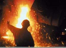
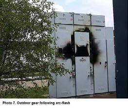
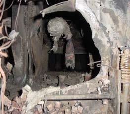
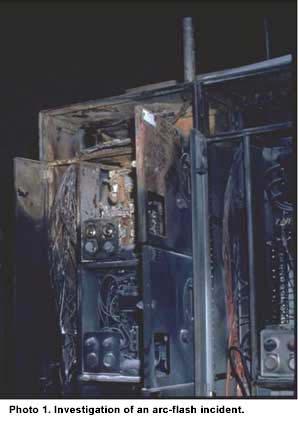
2 Although arc hazards have existed since man began using electricity, increasing deaths, injuries and property loss from arcing faults have lead to increased awareness of the issue and investigation into methods of protection. According to statistics compiled by CapSchell Inc, a Chicago-based research and consulting firm that specializes in preventing workplace injuries and deaths, there are five to ten arc-flash explosions that occur in electric equipment every day, resulting in medical treatment. An arc flash is a breakdown of the air resulting in an arc which can occur where there is sufficient voltage in an electrical system and a path to ground, neutral, or another phase. An arc flash, with a high level of current, in the range of 1000 amps or more, can cause substantial damage, fire or injury. The massive energy released in an arcing fault can instantly vaporize metal in the path of the arc, blasting molten metal and expanding plasma outward with extreme force. The result of the violent event can cause destruction of equipment, fire, and injury, not only to the worker but also to nearby workers. From 1992 to 1999 the customers from one major insurance company reported 228 losses that were attributed to ground faults with a total cost of US $180 million. An arc flash is a breakdown of the air resulting in an arc which can occur where there is sufficient voltage in an electrical system and a path to ground, neutral, or another phase. An arc flash, with a high level of current, in the range 1000 amps or more, can cause substantial damage, fire or injury. The massive energy released in an arcing fault can instantly vaporize metal in the path of the arc, blasting molten metal and expanding plasma outward with extreme force. The result of the violent event can cause destruction of equipment, fire, and injury, not only to the worker but also to nearby workers. With the arc flash hazard a product of fault current and time, the engineering approach to minimizing the hazard is to affect the contributing factors. The major factors determining the level of the arc-flash hazard are the amount of arcing current, the time that it flows, and the distance of the worker from the arc itself. The first two of these three factors can easily be minimized during the design of the electrical system. Current-Limiting Devices Current-limiting fuses and circuit breakers are often used in the design of electrical distribution systems to protect electrical equipment under high available short-circuit conditions (NEC ). They are able to protect the equipment from the significant thermal damage and magnetic forces associated with high shortcircuit currents by actually reducing the current that flows and the time that it flows. Within their current limiting range, they keep the
3 current from reaching its peak during the first ½ cycle. And because they can react so quickly, the current is driven to zero in as little as ¼ cycle, or even less. This great reduction in damaging current and time not only protects equipment from significant short-circuit currents, but naturally also helps protect workers that might be exposed to horrendous arc-flash energies. The difference between a 30,000 ampere arcing fault that lasts for 30 cycles, and a let-through arcing current of 1,000 amperes that lasts for ¼ cycle can be the difference between a worker driving home after work and a ride to the morgue. In practice, the majority of electrical faults experienced in industrial low-voltage systems are phase-to-ground faults. For solidly grounded wye systems, the IEEE Red Book (Std , section 7.2.4)states that A safety hazard exists for solidly grounded systems from the severe flash, arc burning, and blast hazard from any phase-to-ground fault. The same standard recommends a solution to resolve this issue. Section of the IEEE Red Book states that when using High Resistance Grounding, There is no Arc Flash hazard, as there is with solidly grounded systems, since the fault current is limited to approximately 5A. The Red Book is referring here to phase to ground faults. While High Resistance Grounding prevents the propagation of many ground faults into full fledged three phase arcing faults, High Resistance Grounding has no affect on the magnitude of a phase to phase or three phase arcing fault once the fault is initiated. While High Resistance Grounding as a technology was originally applied to industries as diverse as food processing, mining, petrochemical and even commercial installations such as airports, data centers etc to enhance the reliability and uptime of power distribution equipment it is also proven effective in significantly reducing the frequency and severity of arc flash accidents. With between 90% and 98% of electrical faults being phase-to-ground faults, by limiting the fault current to between 5amps and 10amps, there is insufficient fault energy for the arc to re-strike and it self-extinguishes and the hazard frequency is reduced. Nowadays, High Resistance Grounding is being used to replace Solidly Grounded systems for the safety reason noted above and there are design considerations that must be addressed. Fortunately, modern technology helps incorporate these considerations, making the design process straightforward. The original High Resistance Grounding system developed in the 1950 s and 1960 s worked as intended, however, it wasn t able to solve potential safety issues, such as a second ground fault, leaving the ground on the system too long, communications, additional tools to locate a ground fault, and monitoring of the neutral path. When modern relays are integrated into the High Resistance Grounding package, these design considerations are easily resolved. The addition of zero-sequence current transformers on each feeder in the main switchgear and a dedicated ground detection system is all that is required. These can be integrated into new switchgear or retrofitted into existing gear. When a ground fault occurs, the ground relay indicates faulted phase and feeder. This keeps maintenance personnel away from the main switchgear when looking for the ground fault, often

4 allowing him/her to wear lower rated PPE protection. The reason is that personnel will begin looking for the ground fault downstream of main switchgear, where the Arc Flash Hazard is based on the feeder over-current protection device (where arc-flash energies are often lower) and not the main over-current protection (where arc-flash energies are often higher). In addition, the relay has built-in communications to alert personnel if they are not on-site during ground fault. The data logging system will keep track of ground faults until maintenance personnel have a chance to locate the ground fault. This may help associate the ground fault with a faulted piece of equipment by coordinating time/day of ground fault when equipment is running. There is a concern that the first ground will be left on the system and ignored. Since the zerosequence current transformers identify the faulted feeder, the relay has the ability to begin a (user programmable, usually in hours) timer when the ground fault first occurs. Unless the ground fault is removed or the timer is reset, the faulted feeder is shunt-tripped offline. The purpose is to continually remind maintenance personnel to either remove the ground fault or to reset the timer every so many hours. In the event that a second ground fault occurs prior to removing the first ground fault, a phase-toground-to-phase or phase-to-phase fault can occur. When this occurred on original High Resistance Grounded systems, it would cause both feeder circuit breakers and possibly the main circuit breaker to trip. However, the modern relay can be programmed to prevent this and only shunttrip the lesser priority feeder, leaving the more important feeder on-line. A major safety concern is the loss of neutral path, i.e. broken wire from source neutral to resistor or between resistor and ground or even a bad or loose connection. The result is changing from a high resistive grounded system to either an ungrounded or solidly grounded system without anyone knowing it! This would cause severe safety hazards. With modern technology, the neutral path from neutral to ground (including resistor) can be continuously monitored for integrity. If an open or short circuit occurs, the relay will alarm. High Resistance Grounding systems do not protect against the less frequent but still dangerous phase-to-phase or three-phase arcing faults. However, the combined use of High Resistance Grounding for protection from ground faults and its ability to prohibit the escalation of the fault and current-limiting fuses or current limiting circuit breakers for phase-to-phase and three-phase arcing faults is an effective engineering approach to minimizing the arc flash hazard.
5 Webinar Questions and Answers Stan,Hintze "I have a transfer switch with two breakers, as my main service disconnect. Power is through a 480V transformer or Generator. Can I use one HRG for both? There are two methods of inserting a single HRG System with 2 sources You can create another neutral on the common bus that is fed from both sources and ground that new Neutral with a resistor to limit the fault current. This way it doesn t matter which source is on, the system will be protected. You can tie both neutrals together and ground it through a resistor. This method is problematic as the voltage of one neutral may elevate to 277 V. with respect to ground even though it is not connected directly to the system. For example if the transfer switch is on transformer and you are servicing the generator and a ground fault occurs, then the voltage on the Generator neutral will rise to 277 V., unless more costly switches are placed to isolate the neutrals under certain system conditions. Duane,Cieslinski d.l.cieslinski@dowcorning.com, "In 7.2.2, it states: There is no arc flash hazard, as there is with solidly grounded systems, since the fault current is limited to approximately 5A. This is not correct because an arc flash hazard exists on Phase-to-Phase faults. Comments? Chris,Inshaw chris.inshaw@southwestenergysystems.com, The reference to the red book is misleading since it is only referring to ground fault currents and not phase-phase or three-phase faults., Chris,Inshaw chris.inshaw@southwestenergysystems.com, "The probability of an arc-flash with an HRG system may be reduced, but the calculated risk and PPE requirements are not changed. In fact the calculated incident energy is higher for a HRG system.
6 John,Vamos "I would say that use of HRG will greatly reduce the risk of arcing faults on a 480 V system, since the large majority of faults begin life as a line-to-ground fault. But what the others are saying is that it does NOT reduce the hazard that can exist for a three-phase arcing fault, so the required PPE is still based on the worst-case three-phase fault. This is pretty clearly addressed in IEEE There is still an arc-flash hazard since the HRG has no effect on phase-phase or three-phase faults. You are correct. Arc Flash calculations are based on the Arc Flash current, Time, Distance and Bolted Fault Data. There is no way that the grounding system can reduce the Arc Flash Hazard Analysis. The only thing a High Resistance Grounding system can do is limit the fault current of a single phase to ground fault. Now that the fault current is limited to 5 A., the probability of that fault escalating to a phase to phase fault or a three phase fault is greatly reduced. In contrast a single phase to ground fault in a solidly Grounded System has the highest probability of escalating to a three phase fault. The Red Book is stating that most faults in the electrical industry start as Ground Faults. The probability of that fault escalating to a three phase fault in a Solidly Grounded System is High, whereas, the probability of that fault escalating to a three phase fault in a High Resistance Grounded System is Low. If the Statement is interpreted this way, then the statement is true. Michael,Goslak mgoslak@thorengineer.com, "The problem is though IEEE and NFPA formulas are based on 3-phase bolted faults. HRG doesn't even factor into the equation! Until they rewrite the formulas, there's not much we can mathematically do. James,Ghrist jghrist@utilitytec.com, Wouldn't NFPA 70E still require the same PPE as on a solidly grounded system? NFPA 70E and IEEE 1584 calculations are based on 3 Phase faults., Fred,Callison fred_callison@rsconst.com, "Since line to line faults can still occur, would the arc flash boundary and PPE requirements change if a solidly grounded system is changed to HRG?", Lewis,Farinholt, lewis.farinholt@siemens.com, IEEE calculations are based on 3-panse fault currents. Where in their calculation methodology does IEEE allow one to account for the reduced ground fault current due to HRG equipment and thus reduced arc flash levels?,
7 Mark,Simulis, Are you saying that the HRG system does not reduce arc flash levels for phase to phase arcing faults? If this is the case don't we still have to use the worse case hazard level which would be the same as we would have for a solidly grounded system. Dallas,Jacobsen, dallas.jacobsen@pse.com, "I don't understand the quote ""There is no arc flash hazard, as there is with solidly grounded systems, since the fault current is limited to approximately 5A."" There is still phase to phase arcs that have just as high Arc Flash Hazard.", According to IEEE 1584, using High Resistance Grounding System increases the Incident Energy by approximately 30%. This is the only mathematical proof we have that High resistance Grounding works. Now according to the Red Book and the Green Book we can reduce the number of Incidences that an Arc Flash may occur. The purpose of IEEE 1584 is to calculate the Incident Energy in an Arc Flash. We can use the information from the Red, Green, Buff Books to reduce the number of incidences. An Arc Flash can occur on a High resistance Grounded System. When it does, we can calculate the Incident Energy that we need to protect ourselves from, and wear the appropriate PPE. High Resistance Grounding reduces the probability of a single phase fault escalating to a three phase fault. Tim,Malone timothy.p.malone@usa.dupont.com, Is there any discernable difference in arc flash energy with a 3-phase fault on a solidly grounded system versus an HRG system?, Juan,Arango jarango@thielsch.com, "Acknowledged that phase to ground faults have much lower fault current with HRG. However, with no reduction in severity of phase-phase faults, does the Arc Flash PPE category decrease? The equation for calculating Incident Energy from IEEE 1584 is as follows; lg En = K1 + K lg I a G Where E n is the incident energy (J/cm) normalized for time and distance
 As you can see the only term that differentiates the grounding is K 2 K 2 can be either 0, for ungrounded and High resistance grounded")
8 K 1 is for open configuration (no enclosure) and is for box configuration (enclosed equipment) K 2 is 0 for ungrounded and high-resistance grounded systems and is for grounded systems G is the gap between conductors (mm) As you can see the only term that differentiates the grounding is K 2 K 2 can be either 0, for ungrounded and High resistance grounded systems, or for solidly grounded systems If everything else is Identical then the term lg E n for a High Resistance Grounded system is more than a Solidly Grounded System. And since E n =10 lge n. Then the incident energy for a High resistance Grounded System or an ungrounded System is 29.7% greater than for a Solidly Grounded System. According to IEEE 1584, you need to wear PPE with a higher degree of protection due to the High resistance or Ungrounded system. Gerald,Halm jhalm@cmtengr.com, "Since HRG does not reduce L-L fault current, does it meet the legal & safe intent of all Arc- Flash reduction requirements? Making a statement that HRG will eliminate Arc-Flash will be criminal. No one at this stage can state they eliminate Arc Flash Hazards. But HRG can be used with other protection systems to reduce the probability of an Arc Flash. Bill,Poindexter n1874@conocophillips.com, Does anyone know why the NEC does not require detection on ungrounded systems? NEC (B) Ground Detectors. Ungrounded alternating current systems as permitted in (A)(1) through (A)(4) operating at not less than 120 volts and not exceeding 1000 volts shall have ground detectors installed on the system. So, ground detectors are required on ungrounded systems. The problem is that there is no efficient way to
9 find the ground fault when it occurs. Ground detectors are voltage based. You measure the voltage with respect to ground. The voltage on the faulted phase will decrease to 0 volts. The voltage on the un-faulted phases will increase to near the full line-to-line potential. So you now know that you have a fault on C phase. You have no way of finding and more importantly clearing that fault other than cycling every breaker or switch in the plant until it is found. Normally facilities choose the ungrounded system to avoid outages. The only way to find the fault is with an outage, temporary as it might be. Maintenance personnel are the only ones that loose in this situation. You can t find the fault unless you cycle the breakers and you can t cycle the circuit breakers because you need continuity of power. I have stated that most ungrounded facilities I have visited have a ground fault. The maintenance electricians always have more important issues to work on, so they wait for the second fault to clear the system. This is unacceptable, and allowed. Ungrounded systems can easily be converted to High resistance grounded Systems and finding a ground fault can be accomplished without isolating any switches and without opening any covers. We have even rented some Portable units for this purpose. ark,westgate mwestgate@bell-electrical.com, "On its most basic level, is this the same principle as a GFCI outlet in a residential application? No, I would equate a GFCI with a fuse. If the leakage current is greater than 5 ma then the fuse, GFCI would open clearing the fault from the system. High Resistance Grounding actually limits the fault current to a desired value. The GFCI does not limit, it only detects and isolates. Delvis,Gonzalez dgonzalez@directdrivesystems.net, The analysis is based on transformer on simple power systems. Has the HRG systems similar performance on medium voltage generator and motor?, The High Resistance Grounding System can be used on medium voltage as well as low voltage. The principle is the same as low voltage.
10 Michael,Goslak For HRG installations is it essential to run equipment grounding conductor inside the conduit (versus using the conduit for ground conductor)?, The installation does not have to be different than any other installation. If the code allows you to use the conduit as a bonding conductor then it would be allowed in a High resistance Grounded installation. HAROLD,LERAY harold@gulf-south.com, "HRG - ISN'T SECOND FAULT AT 480 VOLTS, NOT 277VOLTS AND GREATER ENERGY THAN AT 277 VOLTS? The second ground fault, if it is on a different phase will be a phase to ground to phase fault. I would not say that there is more energy in the second fault as far as the IEEE 1584 is concerned as it uses a voltage of 0.48kv to calculate the Fault Energy. The attractive part of your question is the second fault. You will know when you are at risk of the second fault, because you would have had a first fault and you are looking for it. I have had systems that are very complex and I can find the fault within an hour. In solidly grounded system there is no warning. You do not know when you are at risk. We also have products that isolate the second fault should it occur. This is done on a priority level. The two faulted feeders communicate with each other and determine which one should trip based on the priority that the user programs into them. Robert,Borunda borundainc@sbcglobal.net, Can HRG be used for hospitals which normally have ground fault protection on some feeders? Donald,Nolte II don.nolte@nexteng.com, What about healthcare applications? Recommended?, We have installed many High Resistance Grounded Systems in Hospitals. In fact hospitals were the preferred customer base for DSP product. This particular product afforded the user the luxury of tripping on the second fault should one occur.
11 Chris,Shiver WHAT IS PROPER SIZING OF HRG RESISTOR IN TERMS OF POWER CAPACITY?, First of all, you must limit the fault current to a value equal to or greater than the capacitive charging current 3I C0. So IR 3I C0. Now the resistor can be rated for I 2 R R watts Steve, Whitfield steve.whitfield@innovene.com, What should be considered when retrofitting 5 KV systems from LRG to HRG systems? Steve Whitfield, When converting any system from LRG (Low Resistance Grounded) to HRG (High Resistance Grounded) the main thing to consider is the sensitivity of the protection system. If your protection is set up to detect a 200 A, or 400 A. ground fault, it may not have the sensitivity to pick up a 5 A, or 10 A. ground Fault. This can easily be overcome. Similarly for converting an Ungrounded System to a High Resistance Grounded system you must ensure that you can detect a fault when one occurs. Osorio,Jorge jorgesoa@yahoo.com.mx, What about existing installations? Is just installing HRG that we solve possible risks? What else we should consider in an industrial installation?, HRG will limit ground fault currents to a low value. You should have an Arc-Flash Hazard assessment performed so you know what the hazards are. You should acquire the appropriate PPE and insure you have good training programs and safety policies. This is just a start. STEVE,ABBOTT stevea@abbottelectric.com, 1. How HRG effect the clearing time of an overcurrent device? 2. Clarify the capacitance shown in many of your diagrams 3. What products I Gard Represent, 1. One of the most beneficial advantages of the (High Resistance Grounded) HRG, Systems is that you do not have to isolate the faulted circuit on the occurrence of a ground fault.. The ground fault current will be limited to less than 10 A. 99% of all overcurrent devices cannot detect a ground fault of this low magnitude.
12 2. The capacitors shown on the diagrams represent the distributed capacitance which exists on your electrical system. They exists in all systems whether they be Ungrounded, High Resistance, Low resistance or Solidly grounded. They are most significant in Ungrounded systems and least significant in Solidly grounded systems. 3 Load ø Aø Bø Cø c c c I r I c Ib Ia I show them as 1 capacitor to simplify the equations. Normally people have great difficulty realizing they exist. Think of it this way, if you have an Ungrounded System, whether ungrounded Wye or Ungrounded Delta operating at 480 V. You know without thinking about it that the voltage from Phase to ground is 277 V. You should not have any reading at all if it was not for the system being capacitively coupled to ground. 3. Please Visit Fred,Callison fred_callison@rsconst.com, "You spoke of using HRG in industrial applications - Do you also recommend HRG for hospital, schools and commercial office buildings? We have used HRG systems in Hospitals, Data Centers, and some loads of commercial buildings. The difficulty in choosing is determining the ration of load that is lighting specifically 277 V. lighting and 480 volt loads like HVAC.
13 sunit,patel What is the cost increase in using the HRG grounded system versus solidly grounded system, Chuck,Powell Cost vs. solid ground. Some people think that the cost of installing an HRG system is higher than a Solidly grounded system. If you take into consideration the savings in not installing a fully rated Neutral bus in your bus duct that will more than pay for the cost of the HRG system alone. Once you include the added productivity and Safety features, then the HRG system is favoured and cost is not the limiting factor Darryl,Pole darryl.pole@lanxess.com, Can HRG systems be applied at medium voltage?, Yes HRG systems can be used in medium voltage systems as per of the NEC and of the CEC. Michelle,Murphy mnmurphy@usit.net, Why is there this requirement in NEC about not having HRG on single phase loads?, Allison,Haluik allison.haluik@arcelormittal.com, Why is it not possible to connect single phase loads directly to HRG systems?, On most single phase loads, normally lighting ballasts, the neutral terminal is designed to have very low voltage insulation with respect to ground. So if a ground fault occurs the voltage of the neutral can elevate to 277 V. on a 480 V. system. The neutral on the single phase loads are not rated for this elevated voltage. If the neutral breaks down to ground then you have bypassed the resistor and you are left with a solidly grounded system. The other issue is that for single phase loads we only switch the phase conductor and not the neutral. So if maintenance is performed on a 277 V. ballast and the switch is in the off position, the risk of a ground fault elevating the neutral to 277 V. exists. As there is no isolation for the neutral, the maintenance personnel is placed in a dangerous position.

14 Brian,Garden What are the hazards of using VFD's on a grounded system?, There are no hazards of using VFDs on Solidly Grounded Systems Chris,Hunkeler chunkeler@syska.com, How do you determine the size of the resistor to use? Is it based upon the available short circuit current?, Donald,Nolte II don.nolte@nexteng.com, How can we calculate the charging current?, Rob,Hugo roberth@sgmengineering.com, How do you size the resistor?, The resistor is sized to limit the fault current to a value equal to or greater than the system charging current. So the first thing you need to do is to determine the system capacitive charging current. This can be done either by direct measurement or by calculations. Now you want to limit the current to at least this value. The resistance will be the line to neutral voltage divided by the current. Walter,Henry whenry@nbpengineers.com, "We design mostly office and classroom buildings. Loads are mostly lights and outlets. Have you seen HRG used for office or classrooms or hospitals? What if a low resistance were used to reduce fault from say 80,000 to 50,000 for lower rated equipment and less arc flash?", I have seen hospitals using High Resistance Grounding at the 600 V. level. When it comes to 120/208 volt systems I have not seen that. Most of the loads in classrooms and offices are 120 V., with a distributed neutral. Resistance grounded systems are not permitted on distributed neutral loads according to the NEC. Oddly enough it is allowed according to the CEC Use (see Appendix B) (1) Neutral grounding devices shall be permitted to be used only on a system involving a true neutral or an artificial neutral, where line-to-neutral loads are not served.
15 (2) Where line-to-neutral loads are not served, provision shall be made to automatically de-energize the system on the detection of a ground fault unless the electrical system is operating at 5 kv or less, in which case it shall be permitted to remain energized on the detection of a ground fault provided that (a) the ground fault current is controlled at 10 A or less; and (b) a visual and/or audible alarm is provided to indicate clearly the presence of the ground fault. (3) Where line-to-neutral loads are served, provision shall be made to automatically de-energize the system on the occurrence of (a) a ground fault; (b) a grounded neutral on the load side of the neutral grounding device; or (c) a lack of continuity of the conductor connecting the neutral grounding device from the neutral point through the neutral grounding device to the system grounding electrode. So 1102 (3) states that single phase to neutral loads can be served with a Neutral Grounding Resistor. This means that an electrician who is changing a 277V or 347 V. ballast with the switch locked out and tagged out will be subjected to a shock hazard on the occurrence of a ground fault anywhere else on that entire system. Michael,Goslak mgoslak@thorengineer.com, Are you kidding? How can you ensure your electrician ONLY drops his screwdriver between one phase and ground? The other 2 phases are only inches away!!!!! This is why IEEE1584 and NFPA70e base everything on 3-phase bolted faults!, Correct the other two phases are inches away. I go to many conferences and I hear stories of people who are racking in breakers with a misaligned stub and it caused a ground fault and an Arc-Flash. Another case had someone testing voltage with a meter and the probe slipped and caused a ground fault and an Arc-Flash. These arc flash incidents could have been avoided by a High Resistance Grounded System. The operator, wearing the appropriate PPE, would have been alarmed that a ground fault occurred, rectified the situation and most importantly hugged his wife and kids when he went home instead of the grim reality that did occur. Now I can not guarantee that electrical accidents will only affect a single phase and ground. There will be incidents that will involve other phases and ground or all three
16 phases, but you should be wearing the appropriate PPE for that. We are not stating that you need to wear less PPE, just because you have a High Resistance grounded system. I can guarantee that if you are working on an electrical system with no faults on it and accidentally contact a single phase to ground, you will walk away and the equipment can be put back into service. No one can not guarantee the same thing with a solidly grounded system. If I had the choice, I would prefer the added insurance with a High Resistance grounded System. But the choice in the end is yours and you are gambling with a lot more than an opinion. Lawrence,Foley larry.foley@givaudan.com, Can HRG be used with GFCI s?, The principle will work. The problem is that UL does not recognize GFCIs above 240 V. So GFCIs in the US are mainly on 120, 240, and 120/208 circuit which are normally single phase and/or distributed neutral circuits, which are not likely to be High Resistance Grounded systems. In Canada, GFCIs are recognized right up to 600 V. and at this voltage High Resistance Grounded Systems are more common. GFCIs isolate the circuits when the leakage is greater than 5mA. HRG limits the fault current to 5A. Both can work on the same system. Pedro,Valverde pedro.valverde@ihs.gov, Can you provide a rating for the small 1:1 transformer and solidly ground secondary for 1 phase loads?, The transformer rating for the 480 X 480/277 V transformer isolating the lighting loads should be sized to supply the power necessary to supply the lighting load. Abraham,Inlong abraham.inlong@siemens.com, Can we use HRG Technology on 208V WYE systems?, 208 Wye systems are normally 120/208 systems with a distributed neutral to derive the 120 V. for single phase loads. If this is the case then no, HRG and not be used. If the 208 V. System is Ungrounded and there are no single phase loads then you can use the HRG Technology.
17 John,Harman "What grounding requirements should be considered when the power company supplies Y to Y transformers? Specifically, grounding separation requirements between the primary and secondary side. Ground on the primary is the same potential as ground on the secondary. This is the case for any transformer, whether Wye-Wye, Wye-Delta, Delta-Wye, or Delta-Delta. The main thing you have to be concerned with is that ground faults return to there point of origin. If the secondary of your transformer is 480 V. and the Neutral is grounded through a 55 ohm resistor then all ground faults on the secondary are limited to 5 A. that ground fault current will not go to the primary. Similarly if you have a ground fault on the primary circuit, then ground potential will remain at ground potential. The nearest upstream breaker on the primary will isolate that fault. Matthew,Martin matthew.martin@ge.com, What is Ontario's current legislation with respect to arc flash requirements?, CSA is currently working on a standard similar to NFPA 70E called CSA-Z462 Workplace Electrical Safety Standard. A draft is ready for review. Donald,Nolte II don.nolte@nexteng.com, I'm not quite sure how to interpret NEC (4)? Seems to limit the use but not per your presentation., NEC (4)(2005) (4) Line-to-neutral loads are not served. NEC (3) (2008) (3) Line-to-neutral loads are not served. The main load for Line-to-neutral loads is lighting loads at 277, and 347 V. When it comes to High resistance Grounded Systems line to neutral loads cannot be used. We overcome this by utilizing smaller transformers that are specifically used to service these loads. This has 2 main benefits. It allows us to isolate the lighting and single phase loads to utilize HRG, It isolates the lighting loads from the main transformer which should lower the bolted fault current and lower the incident Energy for anyone working on lighting.

18 Martin,Troy Presently have 480 volt 3-wire system--y--solidly grounded. No line to neutral loads. Presently have 480 volt lighting loads (i.e. the 1000 watt HID lighting is at 480 volts. If I install HRG can I still use 480 volt lighting--nec Issues?? Or must I install 1:1 480/480 volt isolation transformer. If the lighting loads you have are not Line-to-neutral then there are no issues with the NEC and you can use HRG. Chris,Babin cbabin@cha-llp.com, "Is HRG voltage rated on secondary voltage? For example, if 13.8kv-480/277-Volt, the rating is 277 LN." Michelle,Murphy mnmurphy@usit.net, Arcing current is roughly 50% at 480V. It is much lower percentage for voltages below this. It is 100% or so above 1kV. I am on 1584, The only way I can get values of 50% at 480 V. is if my Bolted Fault current is 700 A. and my Gap is 6mm. As far as voltages above 1000 V., the arcing fault current can range from 90% at 700 A. to 82% at 106,000 A Craig,Brewster cbrewster@bwrcorp.com, What percentage of commercial buildings in the US has HRG?, David,Watters dwatters@hflenz.com, Do you recommend HRG systems for commercial facilities such as data centers who typically do not have qualified electricians?, I am not 100% sure of the number of commercial installations that use HRG in the US. Commercial installations, such as Data Centers are prime locations for High Resistance Grounding. There is usually redundancy in power supplies, with Generation and Uninterruptible Power Supplies. These locations recognize the importance of power continuity. Ground faults typically occur in the loads or in the power delivery system; they rarely develop in the sources. Having multiple sources does not really solve the problem as your generators, UPSs, and transfer switches will usually transfer onto a ground fault when a power outage occurs due to a ground fault. I would like to think that most large Data Centers would have Qualified Electricians, but I am not sure.
19 Dan,Eaton Folks need to be aware that if they use HRG at medium voltages (like 4160 volts) that more energy is being released at the point of the fault. This means it is more likely that a fault will progress to phase to phase fault before you find the location of the fault. Does anyone use HRG at 13.8 kv? We chose to use LRG at 13.8 kv and HRG at 4.16 kv., We have found that as long as the fault limiting current is greater than the System Capacitive Charging current that the HRG system is very useful. If, however the System capacitive Charging current is too high in magnitude, the Low Resistance Grounded (LRG) system will work well. The LRG system usually limits the ground fault current to a value typically Amps for a short duty cycle, 10 seconds to 60 seconds. The benefit of a LRG system is that the fault current is limited to a known value. James,Koryta koryta@indiana.edu, Would it be feasible to install an HRG on a 15 kv circuit that would result in lower PPE requirements in a building with a 15 kv to 480 volt transformer fed by the circuit?, Ground faults do not tend to cross transformers. If you had a Delta-Wye transformer rated 15kV primary and 480 V secondary. The HRG would be placed on the side you want the protection to be on. Typically the HRG will go on the secondary side of this transformer. Putting the HRG system on the 15 Kv. side will not limit the ground fault current on the 480 V side. Furthermore if you put the HRG system on the 480 V. side will not allow you to lower the PPE requirement. Tony,Lewis t.lewis@imerys.com, "If a solidly grounded system is coordinated based on safety and arc flash currents in mind and not the continuous operation of equipment, isn't the solidly grounded system a better method because the fault is isolated immediately. In this case it does not matter if weather the fault is a ground fault or a phase to phase fault. The Fault can only be isolated immediately if it is detected. In a properly coordinated electrical system intentional time delays are placed where the fault current is the greatest. In order for the protective relays to detect an Arcing fault, there must be a current greater than the set point of the protective and it must persist for a time greater than the time delay of the protective relay. Arcing currents are lower than bolted fault currents. It is possible for a low level arcing ground fault to be present on
20 the system and go undetected. This arcing current can propagate into a phase to phase or a three phase fault quickly. In a High Resistance Grounded the arcing ground fault will not propagate into a phase to phase or three phase fault. Aaron,Szura aaron@cavelect.com, "Based on the previous questions, an ungrounded system would be an excellent choice for HRG technology as a grounded system would possibly require additional; work and expense." It is true that the Ungrounded system is the easiest system to convert to the High Resistance grounded System. Many Systems have been converted in the past and I am sure many will convert in the future. We have a portable HRG product that can convert an ungrounded System into an HRG system in a very short time (< 1/2 hour). Some extra time and consideration is required for Solidly Grounded Systems. The expense can be extensive if you are dealing with an installation that was built with very little thought of the process being performed within the installation. For example, if an installation is built and the contractor or engineer chose slash rated breakers, then this installation would not be suited for HRG. The expense can also be minimal. There are a number of benefits in HRG and each installation can be considered. But if you are asking which installation is safer then I would have the say the High Resistance Grounded System. I have had conversations with many designers and the most common concept in this day and age is to meet the minimum requirement stipulated by the NEC or CEC, and meet budget. The operational costs of the installation do not enter into the equation. James,Ghrist jghrist@utilitytec.com, Could you comment briefly on low resistance grounded systems?, Low Resistance Grounded Systems are complicated. The principle is the same as HRG. A resistor is placed between the Neutral and ground to limit the fault current to a desired value for a length of time. This is mainly done to limit the damage at the point of fault and to allow coordination of the electrical system in order to isolate only the faulted circuit. There are a couple of items that you need to consider when using Low Resistance Grounded Systems. The first and by far the most frequent question I am asked is what to limit the fault current to? There is no formula to apply, no rule of thumb, and no parameters you can

21 measure to determine this. You must consider your system protection and determine the minimum value of fault current you can detect. If for example the smallest breaker you have on your system is a 600 A. Frame with 600:5 A. Current Transformers. The minimum pickup on the protection relay for ground fault is 20%. Then the minimum ground fault you can detect is 120 A. However if the main breaker is 2000 A. with 2000:5 A Current Transformers then 400 A. is needed to trip the Main. The second thing to consider is the type of steel you request for the grounding Resistor. Many people today request Stainless Steel for the resistor element, and that it should comply with IEEE32. Of the stainless steels used today, they are similar but not identical. The thing you have to be aware of is that most stainless steel has a temperature coefficient of resistivity. This is an indication of how the resistance changes with respect to temperature. IEEE32 allows the temperature of the resistive element to change 760 C for a short duty resistor. So following is a table of some common stainless steel materials, their temperature coefficient of resistivity and the per unit change in resistance after 10 s. Stainless Steel Temperature Per unit change in Coefficient of Resistance Resistivity(Ω/ C) AISI % AISI % 18SR % 1JR % It is important to note that if the resistance value change is excessive, as with lower quality stainless steel, then there may be insufficient fault current to actuate the over-current relay and the fault will stay on the system and eventually destroy the resistor and whatever distribution equipment it is protecting. An additional safety feature is to use a monitoring relay that provides an alarm should the grounding circuit be compromised due to excessive change in current, loose connections, foreign objects, corrosion or moisture etc.
22 Trent,Chambers "If you limit the ground fault current to say, 5A, how can the OCPD open the circuit? What purpose does it then serve? The Overcurrent Protective Device can not detect a ground Fault current of 5 A. Donald,Nolte II don.nolte@nexteng.com, What about using an inductor vs. resister? You can use any impedance to limit the fault current. An impedance can be a resistor, inductor or capacitor. The resistor is the only element that will limit the current of all harmonic content. The impedance of a capacitor is inversely proportional to the frequency. The impedance of the inductor is directly proportional to the frequency. This can mean that harmonic contributions in the system will react differently. David,Huntley dhuntley@idoa.in.gov, Can I deploy HRG selectively on MV-Dist only while deploying solidly grounded distribution with neutrals down stream?, It is important to keep the grounding consistent throughout the distribution of a single source. If you start with HRG, then you will not have the neutral available to you downstream unless there is another transformer downstream to isolate the two voltages. The only way you may change the grounding method is to transform the voltage with an isolation transformer. Manuel,Cid mcid@homesteadenergy.org, Where do you place the HGR in a wye-delta grounding transformer? For a 13.2 kv system, The three most common ways to limit the fault current for a single phase to ground fault are as follows.
23 Mike,Adams, Can a HRG system be installed in a 120/208v 3 phase system with single phase loads as the primary load? HRG can not be applied on a system which has a distributed Neutral as per CEC , and NEC 250,36 Mike,Gradinjan, mgradinjan@morainepark.edu, "Once the utility grounds their transformers, use of HRG would only limit arcing faults within the facility. Wouldn't this force ground currents through unintended paths back to the utility ground connection?" If these are single phase sources you would not be able to use HRG. This is not true for three phase sources. Ground faults can only return to their sources. Aaron,Szura, aaron@cavelect.com, "With the voltage rising to 480 V between line to ground, wouldn't equipment damage be inevitable? (i.e. lighting, equipment rated at 277v) This would also be a phase loss for 3 phase equipment. Without phase loss protection, what are the other options? Are HRG systems to be only installed in supervised locations?" As far as the load is concerned for an HRG system, it would see 480 V. phase to phase on all three phases regardless if there was a ground fault on the system or not. This is how we achieve the power continuity. 277 Volt loads are not an issue because they will not be allowed on an HRG system. You can have 480 V single phase loads but not 277 V as there is no neutral. You may overcome this by using a 1:1 transformer and deriving another neutral to service loads such as 277 V. lighting. Ken,Cybart, kcybart@littelfuse.com, How do you size a resistor? Does it depend on the size of the transformer? The resistor is required to limit the fault current to a value which is equal to or greater than the Capacitive Charging current. It is independent of the size of the transformer. You can put a 5 A NGR on a 1000KVA transformer or a 5000 KVA transformer. The only limiting factor is the amount of charging current.
24 Steven,Millard, Can you use HRG systems on dc ungrounded systems? Yes we have products that can be used on a DC system. We also have systems which allow you to locate where the fault is on DC networks. Saul,Belloso, saul.belloso@shell.com, What about the use of HRG in Medium Voltages systems? There are no restrictions in the CEC or NEC in reference to voltages and allow HRG systems on greater than 1000 V. The CEC has a limit of 4160 V. in order to maintain power continuity. If you have HRG systems and you wish to trip on the first fault you may do so. Michael,Kelly, kellymw@umkc.edu, When employing a HRG system on an existing system don't you have to determine if the existing equipment can withstand the offset voltage that will occur once the fault happens? If you are employing an HRG system on an Ungrounded system, you can automatically assume that the system can tolerate the increase voltage with respect to ground as the voltage reacts the same way in both these systems. If you want to employ the HRG system to one which is Solidly Grounded, then you must consider the increase in voltage that can occur. Things you need to consider are; Metering PT s as these are most commonly connected Phase to ground for Revenue metering and the voltages are only rated for Phase to neutral potentials. TVSS s as these are also voltage dependant and must be rated full phase to phase potential with respect to ground. Lightning Arrestors, These should be rated for the full line to line potential. As you can see the list is not exhaustive but you will have to analyze the system for suitability.

25 edmund,elizalde, How can HRG technology be applied to UPS system. Will there be a problem with the operation of UPS systems? There are many installations involving UPS systems. There is no problem utilizing HRG on systems that utilize UPSs. In fact it makes complete sense. You have chosen the UPS to maintain power, so why should you trip on the must common type of fault there is? Michelle,Murphy, mnmurphy@usit.net, Is it true that the HRG is not effective for a 3 phase bolted fault? Michelle,Murphy, mnmurphy@usit.net, IEEE 1584 and NFPA 70e do not give credit for HRG. What are your thoughts on this? This is true. HRG will only provide a limit for single phase to ground fault, it will not limit, or assist you in phase to phase or three phase faults. The benefits you receive for having an HRG system are not recognized by IEEE 1584 or NFPA 70E. They are still great benefits as they will save lives. Jeffrey,Turner, jrturner@teg123.com, Are HRG systems primarily used on customer systems served by the utility company or customer owned generator systems? I've used HRG on generator systems but have never seen or used on the utility source of supply. As long as the utility supplied source services 1 facility, there should not be any difficulty in installing an HRG system. We have assisted many of our customers who have Utility transformers and have installed HRG systems. At first it was difficult convincing the Utility and now some of them actually request it.
26 Shane,Vander Kooi, You list the calculation changes at 1kV. I thought the governing arc flash equations were based on IEEE for <600V and NFPA for >600V? According to IEEE 1584 there are two equations for calculating Arcing Current. One equation is used for systems below 1000 V. the other equation is used for systems above 1000 V. NFPA 70E does differentiate between less than 600 V. and greater than 600 V., But they use the same equations as listed in IEEE 1584 and NFPA 70E uses the same voltages as IEEE I can see why the confusion exists.
Webinar: An Effective Arc Flash Safety Program
 Webinar: An Effective Arc Flash Safety Program Daleep Mohla September 10 th, 2015: 2pm ET Agenda Arc Flash Defined and Quantified NFPA 70E / CSA Z 462 - Recent Updates What is the ANSI Z10 Hierarchy of
A DUMMIES GUIDE TO GROUND FAULT PROTECTION
 A DUMMIES GUIDE TO GROUND FAULT PROTECTION A DUMMIES GUIDE TO GROUND FAULT PROTECTION What is Grounding? The term grounding is commonly used in the electrical industry to mean both equipment grounding
Upgrading Your Electrical Distribution System To Resistance Grounding
 Upgrading Your Electrical Distribution System To Resistance Grounding The term grounding is commonly used in the electrical industry to mean both equipment grounding and system grounding. Equipment grounding
ARC FLASH PPE GUIDELINES FOR INDUSTRIAL POWER SYSTEMS
 The Electrical Power Engineers Qual-Tech Engineers, Inc. 201 Johnson Road Building #1 Suite 203 Houston, PA 15342-1300 Phone 724-873-9275 Fax 724-873-8910 www.qualtecheng.com ARC FLASH PPE GUIDELINES FOR
Effective System Grounding
 Effective System Grounding By Andrew Cochran of I-Gard and John DeDad of DeDad Consulting The costs associated with losses stemming from ground faults are staggering. For example, over a seven year period,
The Importance of the Neutral-Grounding Resistor. Presented by: Jeff Glenney, P.Eng. and Don Selkirk, E.I.T.
 The Importance of the Neutral-Grounding Resistor Presented by: Jeff Glenney, P.Eng. and Don Selkirk, E.I.T. Presentation Preview What is high-resistance grounding (HRG)? What is the purpose of HRG? Why
Grounding for Power Quality
 Presents Grounding for Power Quality Grounding for Power Quality NEC 250.53 states that ground resistance should be less than 25 ohms. Is this true? Grounding for Power Quality No! NEC 250.53 states
Electrical Arc Hazards
 Arc Flash Analysis 1996-2009 ETAP Workshop Operation Notes Technology, 1996-2009 Inc. Operation Workshop Technology, Notes: Arc Inc. Flash Analysis Slide 1 Electrical Arc Hazards Electrical Arcs can occur
high RESISTANCE GROUNDING SYSTEM the power to protect www. ElectricalPartManuals. com Instruction Manual C-102
 G e m i n i high RESISTANCE GROUNDING SYSTEM the power to protect Instruction Manual C-102 HIGH RESISTANCE GROUNDING SYSTEM Gemini is a unique, fail safe, all-in-one neutral grounding system, combining
thepower to protect the power to protect i-gard LITERATURE Low and medium voltage
 thepower to protect i-gard LITERATURE Low and medium voltage distribution systems Arc Flash Hazards and High Resistance Grounding Grounding of Standby and Emergency Power Systems Neutral Grounding Resistors
AN EXAMPLE OF A STANDARD ARC FLASH PPE LABELING STRATEGY
 The Electrical Power Engineers Qual-Tech Engineers, Inc. 201 Johnson Road Building #1 Suite 203 Houston, PA 15342-1300 Phone 724-873-9275 Fax 724-873-8910 www.qualtecheng.com AN EXAMPLE OF A STANDARD ARC
2 Grounding of power supply system neutral
 2 Grounding of power supply system neutral 2.1 Introduction As we had seen in the previous chapter, grounding of supply system neutral fulfills two important functions. 1. It provides a reference for the
Electrical Measurement Safety. Sponsored By:
 Electrical Measurement Safety Sponsored By: About the Viewer Panel Slides: Go to the Links tab at the top and click on the link to download the PDF of the slides If you re watching the archive version,
Cause, Effect & Mitigation Strategies
 WSU HANDS ON RELAY SCHOOL 2019 Arc Flash Fault Cause, Effect & Mitigation Strategies Joe Xavier, Technical Manager West Region Arc Flash Fault - Agenda What is an Arc Flash? Why and when does Arc Flash
First Draft Language
 110.16 First Draft Language (B) Service Equipment. In addition to the requirements in (A), service equipment shall contain the following information: (1) Nominal system voltage (2) Arc flash boundary (3)
Section 6: System Grounding Bill Brown, P.E., Square D Engineering Services
 Section 6: System Grounding Bill Brown, P.E., Square D Engineering Services Introduction The topic of system grounding is extremely important, as it affects the susceptibility of the system to voltage
SECTION SHORT CIRCUIT, COMPONENT PROTECTION, FLASH HAZARD AND SELECTIVE COORDINATION STUDY
 SECTION 16075 - SHORT CIRCUIT, COMPONENT PROTECTION, FLASH HAZARD AND SELECTIVE COORDINATION STUDY PART 1 GENERAL 1.1 SUMMARY A. Section Includes: 1. Provide a short-circuit, component protection, flash
Short Circuit Current Calculations
 Introduction Several sections of the National Electrical Code relate to proper overcurrent protection. Safe and reliable application of overcurrent protective devices based on these sections mandate that
Grounding System Theory and Practice
 Grounding System Theory and Practice Course No. E-3046 Credit: 3 PDH Grounding System Theory and Practice Velimir Lackovic, Electrical Engineer System grounding has been used since electrical power systems
THREE PHASE PAD MOUNTED DISTRIBUTION TRANSFORMER ARC FLASH TESTING JUNE 23, 2009 FERRAZ SHAWMUT HIGH POWER LABORATORY NEWBURYPORT, MA
 THREE PHASE PAD MOUNTED DISTRIBUTION TRANSFORMER ARC FLASH TESTING JUNE 23, 2009 FERRAZ SHAWMUT HIGH POWER LABORATORY NEWBURYPORT, MA Witnessed by: Jim Phillips, PE, Consultant Craig DeRouen, ERMCO Director
3Ø Short-Circuit Calculations
 3Ø Short-Circuit Calculations Why Short-Circuit Calculations Several sections of the National Electrical Code relate to proper overcurrent protection. Safe and reliable application of overcurrent protective
Arc Flash Analysis and Documentation SOP
 Arc Flash Analysis and Documentation SOP I. Purpose.... 2 II. Roles & Responsibilities.... 2 A. Facilities Maintenance (FM).... 2 B. Zone Supervisors/ Shop Foremen... 2 C. PMCS & CPC... 2 III. Procedures...
high RESISTANCE GROUNDING SYSTEM the power to protect SLEUTH Instruction Manual C-408EM
 SLEUTH high RESISTANCE GROUNDING SYSTEM SLEUTH the power to protect Instruction Manual C-408EM HIGH RESISTANCE GROUNDING Sleuth Protecting your equipment and processes from damaging ground faults, a resistor
Selective Coordination for Emergency and Legally-Required Standby Power Distribution Systems
 Selective Coordination for Emergency and Legally-Required Standby Power Distribution Systems Presented for the IEEE Central TN Section / Music City Power Quality Group August 1, 2006 By Ed Larsen and Bill
AN EXAMPLE OF A STANDARD ARC FLASH PPE LABELING STRATEGY
 The Electrical Power Engineers Qual-Tech Engineers, Inc. 201 Johnson Road Building #1 Suite 203 Houston, PA 15342-1300 Phone 724-873-9275 Fax 724-873-8910 www.qualtecheng.com AN EXAMPLE OF A STANDARD ARC
Education & Training
 Distribution System Operator Certificate This program provides you with a proficient working knowledge in modern electric power distribution systems. These four classes are designed to walk students through
Numbering System for Protective Devices, Control and Indication Devices for Power Systems
 Appendix C Numbering System for Protective Devices, Control and Indication Devices for Power Systems C.1 APPLICATION OF PROTECTIVE RELAYS, CONTROL AND ALARM DEVICES FOR POWER SYSTEM CIRCUITS The requirements
Arc Flash Analysis Training
 Arc Flash Analysis Training Contact us Today for a FREE quotation to deliver this course at your company?s location. https://www.electricityforum.com/onsite-training-rfq An arc flash analysis study is
Design Approaches for Hospital Distribution Systems With Considerations for Future Expansion, Operator Safety, and Cost
 Design Approaches for Hospital Distribution Systems With Considerations for Future Expansion, Operator Safety, and Cost Adam T. Powell, PE President Emerald Engineering, Inc. Jeffrey L. Small, Sr. Senior
Grounding Recommendations for On Site Power Systems
 Grounding Recommendations for On Site Power Systems Revised: February 23, 2017 2017 Cummins All Rights Reserved Course Objectives Participants will be able to: Explain grounding best practices and code
> the power to protect. Ground Fault Protection on Ungrounded and High Resistance Grounded Systems. Application Guide.
 > the power to protect Ground Fault Protection on Ungrounded and High Resistance Grounded Systems Application Guide www.i-gard.com TABLE OF CONTENTS SUBJECT PAGE 1. Introduction...1 2. Ungrounded Systems...1
2018 Consultant s Handbook Division 26 Electrical ARC Flash Hazard Analysis
 1 Summary 1.1 Provide a complete Arc Flash Hazard Analysis for the project indicated in the accompanying RFP. The Analysis may be performed: independent of the construction project in concert with the
Protection Basics Presented by John S. Levine, P.E. Levine Lectronics and Lectric, Inc GE Consumer & Industrial Multilin
 Protection Basics Presented by John S. Levine, P.E. Levine Lectronics and Lectric, Inc. 770 565-1556 John@L-3.com 1 Protection Fundamentals By John Levine 2 Introductions Tools Outline Enervista Launchpad
How to maximize reliability using an alternative distribution system for critical loads
 White Paper WP024001EN How to maximize reliability using an alternative distribution system for critical loads Executive summary The electric power industry has several different distribution topologies
Need for grounding Codes and Standards for grounding Wind Turbine Generator grounding design Foundation + Horizontal Electrode grounding design
 IEEE PES Transmission and Distribution Conference 2008 Panel Session Large Wind Plant Collector Design Wind Farm Collector System Grounding by Steven W. Saylors, P.E. Chief Electrical Engineer Vestas Americas
Wisconsin Contractors Institute Continuing Education
 IMPORTANT NOTE: You should have received an email from us with a link and password to take your final exam online. Please check your email for this link. Be sure to check your spam folder as well. If you
Industrial Electrician Level 3
 Industrial Electrician Level 3 Industrial Electrician Unit: C1 Industrial Electrical Code I Level: Three Duration: 77 hours Theory: Practical: 77 hours 0 hours Overview: This unit is designed to provide
CHAPTER 15 GROUNDING REQUIREMENTS FOR ELECTRICAL EQUIPMENT
 CHAPTER 15 GROUNDING REQUIREMENTS FOR ELECTRICAL EQUIPMENT A. General In a hazardous location grounding of an electrical power system and bonding of enclosures of circuits and electrical equipment in the
Ground Fault Currents in Unit Generator-Transformer at Various NGR and Transformer Configurations
 Ground Fault Currents in Unit Generator-Transformer at Various NGR and Transformer Configurations A.R. Sultan, M.W. Mustafa, M.Saini Faculty of Electrical Engineering Universiti Teknologi Malaysia (UTM)
EPG. by Chris C. Kleronomos
 April 1994 EFFECTIVE EQUIPMENT GROUNDING ECOS Electronics Corporation by Chris C. Kleronomos The quality of the electrical wiring and grounding in a facility containing sensitive electronic equipment is
Arc Flash Calculation Methods
 Arc Flash Calculation Methods Course No: E04-033 Credit: 4 PDH Velimir Lackovic, Char. Eng. Continuing Education and Development, Inc. 9 Greyridge Farm Court Stony Point, NY 10980 P: (877) 322-5800 F:
ARC FLASH HAZARD ANALYSIS AND MITIGATION
 ARC FLASH HAZARD ANALYSIS AND MITIGATION J.C. Das IEEE PRESS SERIES 0N POWER ENGINEERING Mohamed E. El-Hawary, Series Editor IEEE IEEE PRESS WILEY A JOHN WILEY & SONS, INC., PUBLICATION CONTENTS Foreword
Overview of Grounding for Industrial and Commercial Power Systems Presented By Robert Schuerger, P.E.
 Overview of Grounding for Industrial and Commercial Power Systems Presented By Robert Schuerger, P.E. HP Critical Facility Services delivered by EYP MCF What is VOLTAGE? Difference of Electric Potential
System Protection and Control Subcommittee
 Power Plant and Transmission System Protection Coordination Reverse Power (32), Negative Sequence Current (46), Inadvertent Energizing (50/27), Stator Ground Fault (59GN/27TH), Generator Differential (87G),
{40C54206-A3BA D8-8D8CF }
 Informative Annex D Incident Energy and Arc Flash Boundary Calculation Methods This informative annex is not a part of the requirements of this NFPA document but is included for informational purposes
WHITE PAPER. Medium Voltage On-Site Generation Overview. BY MIKE KIRCHNER Technical Support Manager at Generac Power Systems
 WHITE PAPER Medium Voltage On-Site Generation Overview BY MIKE KIRCHNER Technical Support Manager at Generac Power Systems INTRODUCTION It seems that just about everyone is looking for more power. As our
2014 NEC Changes Part 1
 www.garyklinka.com Page 1 of 8 Instructions: Fee $20 1. Print these pages. 2. Circle the correct answers and transfer them to the answer sheet. 3. Page down to the last page for the verification forms
Unit 3 Magnetism...21 Introduction The Natural Magnet Magnetic Polarities Magnetic Compass...21
 Chapter 1 Electrical Fundamentals Unit 1 Matter...3 Introduction...3 1.1 Matter...3 1.2 Atomic Theory...3 1.3 Law of Electrical Charges...4 1.4 Law of Atomic Charges...4 Negative Atomic Charge...4 Positive
SECTION OVERCURRENT PROTECTIVE DEVICE COORDINATION STUDY
 PART 1 - GENERAL 1.1 DESCRIPTION SECTION 26 05 73 OVERCURRENT PROTECTIVE DEVICE COORDINATION STUDY SPEC WRITER NOTE: Delete between // -- // if not applicable to project. Also, delete any other item or
ADDENDUM NO. 2 PROJECT: COURTLAND PUMP STATION CONTRACT: IFB NO COM.00030
 ADDENDUM NO. 2 PROJECT: COURTLAND PUMP STATION CONTRACT: IFB NO. 2018-008-COM.00030 To: Prospective Bidders of Record Date: December 17, 2018 The following changes, additions, revisions, and/or deletions
3/29/2012 MAIN TOPICS DISCUSSED ELECTRICAL SYSTEMS AND ELECTRIC ENERGY MANAGEMENT SECTION K ELECTRIC RATES POWER COMPUTATION FORMULAS.
 MAIN TOPICS DISCUSSED Electric Rates Electrical system utilization ELECTRICAL SYSTEMS AND ELECTRIC ENERGY MANAGEMENT SECTION K Power quality Harmonics Power factor (Cos phi) improvement Section K - 2 ELECTRIC
MECKLENBURG COUNTY. Land Use and Environmental Service Agency Code Enforcement 9/8/10 ELECTRICAL CONSISTENCY MEETING. Code Consistency Questions
 conduit? 9/8/10 ELECTRICAL CONSISTENCY MEETING Code Consistency Questions 1. Can branch circuits of different services be installed in the same Yes, see 300.3(C)(1) for conductors of different systems
Ground Fault Protection on Ungrounded and High Resistance Grounded Systems APPLICATION GUIDE
 Ground Fault Protection on Ungrounded and High Resistance Grounded Systems APPLICATION GUIDE HRG C-400EA Application Guide, February 2015 ABOUT I-GARD I-Gard s commitment to electrical safety provides
Copper Core & Coil Transformer
 Copper Core & Coil Transformer Transformer Stomach Pain Normal Operation: Transformer internal structures and windings are subjected to mechanical forces due to the magnetic forces. Through fault current
Steve Kovach District Sales Engineer
 Steve Kovach District Sales Engineer 630-740-7463 Steveekovach@Eaton.com Institute of Electrical and Electronics Engineers American Society of Safety Engineers 1 Electrical Hazards Electrical Hazards Shock
PRODUCTIVELY SAFER LOCK-OUT TAG-OUT PROCEDURE
 PRODUCTIVELY SAFER LOCK-OUT TAG-OUT PROCEDURE with PESDs WRITTEN BY: Philip B. Allen, Owner and CEO 1515 W. Kimberly Road Davenport, Iowa 52807, USA 1.800.280.9517 www.graceport.com PRODUCTIVELY SAFER
Preface...x Chapter 1 Electrical Fundamentals
 Preface...x Chapter 1 Electrical Fundamentals Unit 1 Matter...3 Introduction...3 1.1 Matter...3 1.2 Atomic Theory...3 1.3 Law of Electrical Charges...4 1.4 Law of Atomic Charges...5 Negative Atomic Charge...5
Arc Flash Hazard and Mitigation 2 nd Workshop on Power Converters for Particle Accelerators June 14 16, 2010
 Arc Flash Hazard and Mitigation 2 nd Workshop on Power Converters for Particle Accelerators June 14 16, 2010 Paul Bellomo June 14-16, 2010 2nd Workshop on Power Converters for Particle Accelerators - Arc
Capstone Turbine Corporation Nordhoff Street Chatsworth CA USA Phone: (818) Fax: (818) Web:
 Fax: (818) Web:") Phone: (818) 734-5300 Fax: (818) 734-5320 Web: www.capstoneturbine.com Technical Reference Capstone MicroTurbine Electrical Installation 410009 Rev F (October 2013) Page 1 of 31 Capstone Turbine Corporation
Phone: (818) 734-5300 Fax: (818) 734-5320 Web: www.capstoneturbine.com Technical Reference Capstone MicroTurbine Electrical Installation 410009 Rev F (October 2013) Page 1 of 31 Capstone Turbine Corporation
STANDARDIZING ARC FLASH PPE LABELS
 The Electrical Power Engineers Qual-Tech Engineers, Inc. 01 Johnson Road Building #1 Suite 03 Houston, PA 1534-1300 Phone 74-873-975 Fax 74-873-8910 www.qualtecheng.com STANDARDIZING ARC FLASH PPE LABELS
Paul Dobrowsky Innovative Technology Services
 Significant Changes to NFPA 70E -2009 Edition Paul Dobrowsky Innovative Technology Services 2008 IEEE PCIC 1 Repeat Presentation This has been previously presented 2008 IEEE Electrical Safety Workshop
The InterNational Electrical Testing Association Journal. BY STEVE TURNER, Beckwith Electric Company, Inc.
 The InterNational Electrical Testing Association Journal FEATURE PROTECTION GUIDE 64S Theory, Application, and Commissioning of Generator 100 Percent Stator Ground Fault Protection Using Low Frequency
FTTH ENGINEERING AND INSTALLATION INTRODUCTION
 1 FTTH ENGINEERING AND INSTALLATION INTRODUCTION GROUNDING FTTH SYSTEMS AT THE HOME. By Dean Mischke, P.E., V.P. Grounding and bonding. Why are we worried about such an old school concept in the modern
Busbars and lines are important elements
 CHAPTER CHAPTER 23 Protection of Busbars and Lines 23.1 Busbar Protection 23.2 Protection of Lines 23.3 Time-Graded Overcurrent Protection 23.4 Differential Pilot-Wire Protection 23.5 Distance Protection
Our Brands. Where we are?
 CATALOG 2019 Our Brands Aktif trade mark for Measuring, Protection, Automatic Meter Reading, Billing and Energy Management Software. by Aktif Aktif trade mark for Measuring, Protection, Control and Power
Safety through proper system Grounding and Ground Fault Protection
 Safety through proper system Grounding and Ground Fault Protection November 4 th, 2015 Presenter: Mr. John Nelson, PE, FIEEE, NEI Electric Power Engineering, Inc. Event to start shortly Scheduled time:
OPERATING, METERING AND EQUIPMENT PROTECTION REQUIREMENTS FOR PARALLEL OPERATION OF LARGE-SIZE GENERATING FACILITIES GREATER THAN 25,000 KILOWATTS
 OPERATING, METERING AND EQUIPMENT PROTECTION REQUIREMENTS FOR PARALLEL OPERATION OF LARGE-SIZE GENERATING FACILITIES GREATER THAN 25,000 KILOWATTS AND MEDIUM-SIZE FACILITIES (5,000-25,000KW) CONNECTED
GROUND-FAULT PROTECTION ON RESISTANCE-GROUNDED POWER-DISTRIBUTION SYSTEMS WITH ADJUSTABLE-SPEED DRIVES 1. Modified_103007
 GROUND-FAULT PROTECTION ON RESISTANCE-GROUNDED POWER-DISTRIBUTION SYSTEMS WITH ADJUSTABLE-SPEED DRIVES 1 TWO BASIC PROBLEMS 1. Prevent nuisance or false trips because of noise on loads or feeders without
Single Earthed Neutral and Multi Earthed Neutral. Single Earthed Neutral and Multi Earthed Neutral: Multi Grounded Neutral System (MEN):
:") Single Earthed Neutral and Multi Earthed Neutral. SEPTEMBER 6, 2011 5 COMMENTS Single Earthed Neutral and Multi Earthed Neutral: In Distribution System Three Phase load is unbalance and non linear so The
Single Earthed Neutral and Multi Earthed Neutral. SEPTEMBER 6, 2011 5 COMMENTS Single Earthed Neutral and Multi Earthed Neutral: In Distribution System Three Phase load is unbalance and non linear so The
Healthcare Isolation Power Systems. Presented by: David Knecht
 Healthcare Isolation Power Systems Presented by: David Knecht E-Mail: David.Knecht@Bender-us.com Healthcare Isolation Power Systems Theory Offer Codes & Standards FAQs Isolated Power System Purpose To
ECE 528 Understanding Power Quality
 ECE 528 Understanding Power Quality http://www.ece.uidaho.edu/ee/power/ece528/ Paul Ortmann portmann@uidaho.edu 208-316-1520 (voice) 1 Today Wiring and grounding Why it s important References Terms and
APQline Active Harmonic Filters. N52 W13670 NORTHPARK DR. MENOMONEE FALLS, WI P. (262) F. (262)
 F. (262)") APQline Active Harmonic Filters N52 W13670 NORTHPARK DR. MENOMONEE FALLS, WI 53051 P. (262) 754-3883 F. (262) 754-3993 www.apqpower.com Power electronic equipment and AC-DC power conversion equipment contribute
APQline Active Harmonic Filters N52 W13670 NORTHPARK DR. MENOMONEE FALLS, WI 53051 P. (262) 754-3883 F. (262) 754-3993 www.apqpower.com Power electronic equipment and AC-DC power conversion equipment contribute
Description & Applications Questions & Answers Selection Charts Single Phase Selection Charts Three Phase...
 SECTION BUCK-BOOST TRANSFORMERS A simple and economical way to correct offstandard voltages... from 95 to 500 volts; single and three phase, in sizes up to 60 kva. Simplified buck-boost rating charts make
TECHNICAL BULLETIN 004a Ferroresonance
 May 29, 2002 TECHNICAL BULLETIN 004a Ferroresonance Abstract - This paper describes the phenomenon of ferroresonance, the conditions under which it may appear in electric power systems, and some techniques
American Electrical Institute
 American Electrical Institute Oregon Electricians Continuing Education Grounding & Bonding (Article 250) 4 Hours American Electrical Institute PO Box 31131 Spokane, WA 99223 www.aeitraining.com Article
CHAPTER 2 ELECTRICAL POWER SYSTEM OVERCURRENTS
 CHAPTER 2 ELECTRICAL POWER SYSTEM OVERCURRENTS 2-1. General but less than locked-rotor amperes and flows only Electrical power systems must be designed to serve in the normal circuit path. a variety of
A controlled arc-flash, produced in a flashtube. Even though the energy level used is fairly low (85 joules), the low-impedance, low-inductance
, the low-impedance, low-inductance") An arc flash (also called a flashover), which is distinctly different from the arc blast, is part of an arc fault, a type of electrical explosion or discharge that results from a low-impedance connection
An arc flash (also called a flashover), which is distinctly different from the arc blast, is part of an arc fault, a type of electrical explosion or discharge that results from a low-impedance connection
A Guide to Establish an Arc Flash Safety Program for Electric Utilities
 A Guide to Establish an Arc Flash Safety Program for Electric Utilities by Craig Clarke, P.E. Eaton Corporation 50 Soccer Park Rd. Fenton, MO 63026 (636) 717-3406 CraigClarke@Eaton.com Ilanchezhian Balasubramanian,
SECTION POWER SYSTEMS STUDIES
 PART 1 - GENERAL 1.1 RELATED SECTIONS: Refer to Division 15 for Mechanical requirements. Refer to Division 16 for Electrical requirements. 1.2 OBJECTIVE: A. The short-circuit study is to calculate the
DC ARC FLASH. THE IMPLICATIONS OF NFPA 70E 2012 ON BATTERY MAINTENANCE
 DC ARC FLASH. THE IMPLICATIONS OF NFPA 70E 2012 ON BATTERY MAINTENANCE William Cantor, P.E. TPI Exton, PA 19341 Phil Zakielarz TPI Exton, PA 19341 Mario Spina Verizon Wireless Uniontown, OH 44685 Abstract
TEACHER ASSESSMENT BLUEPRINT ELECTRICAL CONSTRUCTION TECHNOLOGY. Test Code: 5171 Version: 01
 TEACHER ASSESSMENT BLUEPRINT ELECTRICAL CONSTRUCTION TECHNOLOGY Test Code: 5171 Version: 01 Specific Competencies and Skills Tested in this Assessment: OSHA Regulations and Electrical Safety Practices
PREFACE ********************************************************** IT IS NOT INTENDED THAT THESE STANDARDS BE COPIED AND USED AS A SPECIFICATION!
 PREFACE This publication has been prepared as a guide for Architectural and Engineering (A&E) firms in the preparation of documents for the design and construction of new structures and the remodeling
1. All electrical switches and outlets used shall be equal to Hubbell heavy duty, specification grade or equivalent quality.
 PART 1: GENERAL 1.01 Wiring Devices A. This section of the standard includes design requirements for wiring connections, including receptacles and switches to equipment specified in other sections. 1.02
SAFETY AND HEALTH STANDARD ELECTRICAL GROUNDING Effective Date: 07/17/10 Standard: Document Number: KUCSH0039 Rev: 4
 SAFETY AND HEALTH STANDARD ELECTRICAL GROUNDING Effective Date: 07/17/10 Standard: 16.10 Document Number: KUCSH0039 Rev: 4 16.10.1 INTRODUCTION 16.10.1.1 The intent of this standard is to ensure that continuity
Chapter 1. Applied Grounding and Bonding. Applied Grounding and Bonding 9/18/2011. Introduction. Introduction. Paul Dobrowsky Member NEC Panel 5
 Applied Grounding and Bonding Paul Dobrowsky Member NEC Panel 5 1 Introduction This presentation is a representative sample from the following Chapters of Applied Grounding and Bonding. Chapter 1, Introduction
OPTIMIZING MAINS IMPEDANCE: REAL WORLD EXAMPLES by Judith M. Russell Consulting Electrical Engineer PowerLines
 by Judith M. Russell Consulting Electrical Engineer PowerLines Introduction Power Quality has historically been quantified in terms of voltage. Metering equipment measures RMS voltage level, voltage sags
Key factors to maintaining arc flash safety
 APPLICATI TE Key factors to maintaining arc flash safety Arc flash and blast When an arc fault occurs, the result is a massive electrical explosion. The light and heat emitted by the explosion is known
NFPA-70E. Electrical Safety in the Workplace. Standard for Edition
 NFPA-70E Standard for Electrical Safety in the Workplace 2015 Edition NFPA-70E 90.1 Purpose. The purpose of this standard is to provide a practical safe working area for employees relative to the hazards
Ground Fault Location. Turbo Sleuth. Instruction Manual
 Ground Fault Location Turbo Sleuth Instruction Manual 7615 Kimbel Street, Mississauga, Ontario Canada L5S 1A8 Tel: (905)673-1553 Fax: (905)673-8472 Toll Free: 1-888-RESISTR 737-4787 www.ipc-resistors.com
Strategies for design 600V large modular UPS for critical power applications
 White Paper Markets Served Data centers Strategies for design 600V large modular UPS for critical power applications Executive summary Today s transformerless UPS systems are significantly smaller and
GOOD GROUNDING PRACTICES. A Brief Introduction to the Basics of Electrical Grounding for Power Systems
 GOOD GROUNDING PRACTICES A Brief Introduction to the Basics of Electrical Grounding for Power Systems Introduction to Grounding TABLE OF CONTENTS 1.0 Introduction to Grounding 2.0 Standard Industrial Grounding
This section applies to the requirements for the performance of power system studies by both the Design Engineer and the Contractor.
 Basis of Design This section applies to the requirements for the performance of power system studies by both the Design Engineer and the Contractor. Background Information A Short Circuit and Coordination
Arc Flash and NFPA 70E
 Arc Flash and NFPA 70E Presented by: J.D. Kyle Safe Work Practices Wearing Proper PPE? OSHA 1910.333 (a) (1) not to work hot or live except : 1. De energizing introduces additional or increased hazards
GENERATOR INTERCONNECTION APPLICATION Category 5 For All Projects with Aggregate Generator Output of More Than 2 MW
 GENERATOR INTERCONNECTION APPLICATION Category 5 For All Projects with Aggregate Generator Output of More Than 2 MW ELECTRIC UTILITY CONTACT INFORMATION Consumers Energy Interconnection Coordinator 1945
NOTICE ER Roland Flood Pumping Station Arc Flash Study
 NOTICE This document contains the expression of the professional opinion of SNC-Lavalin Inc. (SLI) as to the matters set out herein, using its professional judgment and reasonable care. It is to be read
TECHNICAL INFORMATION
 NEUTRAL GROUNDING RESISTORS TECHNICAL INFORMATION 4750 Olympic Blvd. Erlanger, KY 41018 USA Phone: 859-283-0778 Toll-Free: 800-537-6144 FAX: 859-283-2978 Web: www.postglover.com With over 130 years of
2015 NFPA 70E. SESHA 2015 ARIZONA MINI CONFERENCE December 10, 2015 Intel Corporation
 2015 NFPA 70E SESHA 2015 ARIZONA MINI CONFERENCE December 10, 2015 Intel Corporation Introduction Jeffrey A. Pugh, P.E. Pugh Engineering LLC Bachelor of Science Degrees in Electrical Engineering and Computer
National Marine Manufacturers Association Compliance Specialist Examination A.C. Electrical (2018 Model Year) ABYC E-11 Supplement 56
 ABYC E-11 Supplement 56") 1. Two Electrical Technicians are discussing markings that are required for AC wiring. Tech A says that AC conductors must be rated for 600 volts and must have their jackets and individual conductors marked
1. Two Electrical Technicians are discussing markings that are required for AC wiring. Tech A says that AC conductors must be rated for 600 volts and must have their jackets and individual conductors marked
2/15/2015. Current will always try to return to its source. In order for there to be current, there must be a complete circuit
 Current will always try to return to its source In order for there to be current, there must be a complete circuit Current will take as many paths or circuits available to it to return to the source The
SWITCHING SAFETY & RELIABILITY CONFERENCE
 SWITCHING SAFETY & RELIABILITY CONFERENCE JARGON WORKSHEET Energize (v) Energize is the process of applying rated voltage to circuit or equipment. Modified IEEE or OSHA from Adj. to verb. To make a piece