Readings: FC: p : lead compensation. 9/9/2011 Classical Control 1
|
|
|
- Cody Willis
- 6 years ago
- Views:
Transcription


1 MM0 Frequency Response Design Readings: FC: p : lead compensation 9/9/20 Classical Control
2 What Have We Talked about in MM9? Control design based on Bode plot Stability margins (Gain margin and phase margin) Transient performance Steady-state performance Nyquist Diagram What s Nyquist diagram? What we can gain from Nyquist diagram Matlab functions: bode(), margin(), nyquist() 9/9/20 Classical Control 2
3 Nyquist Criterion for Stability (MM9) The Nyquist criterion states that: P = the number of open-loop (unstable) poles of G(s)H(s) N = the number of times the Nyquist diagram encircles clockwise encirclements of - count as positive encirclements counter-clockwise (or anti-clockwise) encirclements of - count as negative encirclements Z = the number of right half-plane (positive, real) poles of the closed-loop system The important equation: Z = P + N 9/9/20 Classical Control 3
4 Goals for this lecture (MM0) An illustrative example Frequency response analysis Frequency response design Lead and lag compensators What s a lead/lag compensator? Their frequency features A systematical procedure for lead compensator design A practical design example Beam and Ball Control 9/9/20 Classical Control 4
5 An Illustrative Example: Antenna Position Control Control system design for a satellite tracking antenna (one-dimentional) Design specifications: Overshoot to a step input less than 6%; Settling time to 2% to be less than 0 sec.; Tracking error to a ramp input of slope 0.0rad/sec to be less than 0.0rad; Sampling time to give at at least 0 samples in a rise time. 9/9/20 Classical Control 5
6 9/9/20 Classical Control 6 System model: Transfer function: T c T d B J... B t T t u J B a a s s s U s c ) ( ) ( 0.,, ) ( ) ( ) ( Example: Mathematical Modeling
7 Example: Open-Loop Analysis Transfer function: ( s) B Tc ( t), a 0., u( t) U( s) s s( ) J B a Open-loop properties Step response Impulse response impulse(tf(,[0 0])); figure; step(tf(,[0 0]),0) Stability? 9/9/20 Classical Control 7
8 Example: Possible Control Structure K G(s) KD(s) G(s) G(s) D(s) G(s) KD(s) D2(s) Different control structures Cascade controller: Gain, dynamic compensator? Feedback controller: Gain, dynamic compensator? Single or multiple loops?... 9/9/20 Classical Control 8
9 Example: Just Gain Controller? sys=tf(,[0 0]), step(feedback(00*sys,)) K G(s) sys=tf(,[0 0]), s^2 + s rlocus(sys) 9/9/20 Classical Control 9
10 syscl=feedback(0.*sys,); bode(syscl) ; figure, margin(0.*sys) Closed-loop transfer function s^2 + s /9/20 Classical Control 0
11 Dynamic Compensation Objective: If a satisfactory process dynamics can not be obtained by a gain adjustment alone, some modification or compensation of the process dynamics is needed +KD(s)G(s)=0 Controller KD(s) Plant G(s) 9/9/20 Classical Control
12 Lead and Lag Compensators Lead compensation: acts mainly to lower rise time and decrease the transient overshoot: D(s)=(s+z)/(s+p) with z < p Lag compensation: acts mainly to improve the steadystate accuracy: D(s)=(s+z)/(s+p) with z > p Compensationis typically placed in series with the plant in the feedforward path Controller KD(s) Plant G(s) 9/9/20 Classical Control 2
13 Frequency Properties of Lead and Lag 9/9/20 Classical Control 3
14 Lead and PD Controllers (I) PD compensation: D(s)=K(T D s+) Increasing the phase margin Amplify the high frequency noise Lead compensation: D(s)=K(Ts+)/(Ts+), < 9/9/20 Classical Control 4
15 Lead and PD Controllers (II) Lead compensation: D(s)=K(Ts+)/(Ts+), < Lead compensator is a high-pass filter (app.pd control) It is used whenever substantial improvement in damping is required The maximum phase contribution is Example: sysd=tf([0 ],[ ]) bode(sysd) max T sin sin max max 9/9/20 Classical Control 5
16 Example: PD Controller for Antenna Control (I) Design the low frequency gain K with respect to the steadystate error specification: Tracking error to a ramp input of slope 0.0rad/sec to be less than 0.0rad Ramp Input (R(s) = /s^2): (MM5) Antenna system case... K= 9/9/20 Classical Control 6
17 Example: PD Controller for Antenna Control (II) PD controller: D(s)=0s+ sysd=tf(,[ ])*tf([0.0.0],); syscl2=feedback(sysd,); step(syscl2) Check whether this controller is ok? 9/9/20 Classical Control 7
18 Example: Intuitive Lead Design Design the low frequency gain K with respect to the steadystate error specification Antenna system case... K= Lead controller: D(s)=(0s+)/(s+) sysd=tf(,[ ])*tf([0.0.0],[ ]); syscl3=feedback(sysd,); step(syscl3) 9/9/20 Classical Control 8
19 Example: Comparison of PD and Lead Design bode(syscl2,syscl3); grid 9/9/20 Classical Control 9
20 Goals for this lecture (MM0) An illustrative example Frequency response analysis Frequency response design Lead and lag compensators What s a lead/lag compensator? Their frequency features A systematical procedure for lead compensator design 9/9/20 Classical Control 20
21 Lead Compensator Design Procedure (I) Step : Design the low frequency gain K with respect to the staedy-state error specification Antenna system case... K= Step Input (R(s) = /s): Ramp Input (R(s) = /s^2): Parabolic Input (R(s) = /s^3): 9/9/20 Classical Control 2
22 Lead Compensator Design Procedure (II) Step 2: Determine the needed phase lead Original system PM: sys=tf(,[0 0]), margin(sys)... PM=8 at Expected PM: Expected overshoot limit (6%) Dampling ratio ξ 0.5 Expected PM 00*0.5=50 degree Directly needed phase lead: 50-8=32 degree Expected phase lead: 32+ (7~0) degree 9/9/20 Classical Control 22
23 Lead Compensator Design Procedure (III) Lead compensation: D(s)=K(Ts+)/(Ts+), < Step 3: Determine coefficient α sin sin max max Step 4: Determine coefficient T T max ( n / 2) sin sin max T sin sin max max 9/9/20 Classical Control 23
24 Lead Compensator Design Procedure (IV) Step 5: Draw the compensated frequency response, check PM sysd=tf([4.622 ],[.037 ]); sysc=sys*sysd; margin(sysc); step(feedback(sysc,)) 9/9/20 Classical Control 24
25 Why this Lead Compensator doesn t work? (I) Check the poles & zeros of the closed-loop... syscl=feedback(sysc,); pzmap(syscl); Compare with a standard 2nd-order system... Sys2=tf(0.3099, conv([ i], [ i])) ; step(feedback(sysc,),sys2) 9/9/20 Classical Control 25
26 Lead Compensator Design Procedure (V) Step 6: Iterate on the design until all specifications are met sysd=tf([ ],[.09 ]) ; sysc=sys*sysd; margin(sysc); syscl=feedback(sysc,); step(syscl) sysd=tf([9 ],[ ]); syscl=feedback(sys*sysd,); step(syscl) T D ( s ) max sin sin max max s s ( n /.5) sin sin /9/20 Classical Control 26
27 9/9/20 Classical Control 27

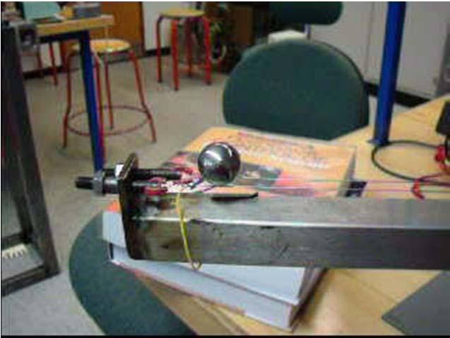
28 System: A ball rolls along the track of a beam that is pivoted at some position. Objective: To steadily place the ball at any given position along the track Strategy: To control the track angle through the control of a servo motor 4. What s B&B System? 9/9/20 Classical Control 28

29 4.2 Why focus on B&B System? The ball and beam apparatus demonstrates the control problems associated with unstable systems. An example of such a system is a missile during launch; active control is required to prevent the missile going unstable and toppling over. 9/9/20 Classical Control 29


30 4.4 AUE Beam and Ball System Implement at least one control method 5-0% overshoot and 3-6 second settling time The potentiometer and axle a hybrid stepping motor TI MSP430 fix-point 9/9/20 Classical Control 30
31 4.4. Modelling the AUE B&B System r B R 2 p 2 p Lagrangian modelling technique Block diagram of stepping motor and load r s m g s J 2 ball m s 2 R 9/9/20 Classical Control 3
32 4.4.2 Analysis of the AUE B&B From the nyquist plot, it can be Observed that the system is unstable since - is encircled clockwise by the nyquist plot System The system is unstable if it is exposed to a step input. From this can it be concluded that the system needs some kind of controller. 9/9/20 Classical Control 32
33 4.4.3 Control Strategy for the B&B System Cascade control Master loop (outer loop) Slave loop (inner loop) 9/9/20 Classical Control 33

34 4.4.4 Control Design for Slave Loop The block control contains the P-controller, Kp2. The slave loop must be faster enough (e.g., 0 times faster) comparing with the master loop kp s Through bode plot it can be seen that the system has a cutoff frequency at appr. 5 rad/sec The system is settled in approximately 0.3 sec 9/9/20 Classical Control 34
 D 7.")


35 4.4.5 Control Design for Master Loop Kp( s ) D s s the system has a phase margin of 47.5 deg at a frequency of.38 Hz 9/9/20 Classical Control 35

36 4.4.6 Simulation Tests 9/9/20 Classical Control 36


37 4.4.7 Real Test Videos 9/9/20 Classical Control 37

38 Exercise Could you repeat the antenna design using. Continuous lead compensation; 2. Emulation method for digital control; Such that the design specifications: Overshoot to a step input less than 5%; Settling time to % to be less than 4 sec.; Tracking error to a ramp input of slope 0.0rad/sec to be less than 0.0rad; Sampling time to give at at least 0 samples in a rise time. (Write your analysis and program on a paper!) 9/9/20 Classical Control 38
Outline. Digital Control. Lecture 3
 Outline Outline Outline 1 ler Design 2 What have we talked about in MM2? Sampling rate selection Equivalents between continuous & digital Systems Outline ler Design Emulation Method for 1 ler Design
Frequency Response Analysis and Design Tutorial
 1 of 13 1/11/2011 5:43 PM Frequency Response Analysis and Design Tutorial I. Bode plots [ Gain and phase margin Bandwidth frequency Closed loop response ] II. The Nyquist diagram [ Closed loop stability
JUNE 2014 Solved Question Paper
 JUNE 2014 Solved Question Paper 1 a: Explain with examples open loop and closed loop control systems. List merits and demerits of both. Jun. 2014, 10 Marks Open & Closed Loop System - Advantages & Disadvantages
CDS 101/110: Lecture 8.2 PID Control
 CDS 11/11: Lecture 8.2 PID Control November 16, 216 Goals: Nyquist Example Introduce and review PID control. Show how to use loop shaping using PID to achieve a performance specification Discuss the use
ANNA UNIVERSITY :: CHENNAI MODEL QUESTION PAPER(V-SEMESTER) B.E. ELECTRONICS AND COMMUNICATION ENGINEERING EC334 - CONTROL SYSTEMS
 B.E. ELECTRONICS AND COMMUNICATION ENGINEERING EC334 - CONTROL SYSTEMS") ANNA UNIVERSITY :: CHENNAI - 600 025 MODEL QUESTION PAPER(V-SEMESTER) B.E. ELECTRONICS AND COMMUNICATION ENGINEERING EC334 - CONTROL SYSTEMS Time: 3hrs Max Marks: 100 Answer all Questions PART - A (10
ANNA UNIVERSITY :: CHENNAI - 600 025 MODEL QUESTION PAPER(V-SEMESTER) B.E. ELECTRONICS AND COMMUNICATION ENGINEERING EC334 - CONTROL SYSTEMS Time: 3hrs Max Marks: 100 Answer all Questions PART - A (10
Dr Ian R. Manchester Dr Ian R. Manchester Amme 3500 : Root Locus Design
 Week Content Notes 1 Introduction 2 Frequency Domain Modelling 3 Transient Performance and the s-plane 4 Block Diagrams 5 Feedback System Characteristics Assign 1 Due 6 Root Locus 7 Root Locus 2 Assign
CDS 101/110: Lecture 9.1 Frequency DomainLoop Shaping
 CDS /: Lecture 9. Frequency DomainLoop Shaping November 3, 6 Goals: Review Basic Loop Shaping Concepts Work through example(s) Reading: Åström and Murray, Feedback Systems -e, Section.,.-.4,.6 I.e., we
Dr Ian R. Manchester
 Week Content Notes 1 Introduction 2 Frequency Domain Modelling 3 Transient Performance and the s-plane 4 Block Diagrams 5 Feedback System Characteristics Assign 1 Due 6 Root Locus 7 Root Locus 2 Assign
EC CONTROL SYSTEMS ENGINEERING
 1 YEAR / SEM: II / IV EC 1256. CONTROL SYSTEMS ENGINEERING UNIT I CONTROL SYSTEM MODELING PART-A 1. Define open loop and closed loop systems. 2. Define signal flow graph. 3. List the force-voltage analogous
ME451: Control Systems. Course roadmap
 ME451: Control Systems Lecture 20 Root locus: Lead compensator design Dr. Jongeun Choi Department of Mechanical Engineering Michigan State University Fall 2008 1 Modeling Course roadmap Analysis Design
 EC6405 - CONTROL SYSTEM ENGINEERING Questions and Answers Unit - II Time Response Analysis Two marks 1. What is transient response? The transient response is the response of the system when the system
Lecture 7:Examples using compensators
 Lecture :Examples using compensators Venkata Sonti Department of Mechanical Engineering Indian Institute of Science Bangalore, India, This draft: March, 8 Example :Spring Mass Damper with step input Consider
Course Outline. Time vs. Freq. Domain Analysis. Frequency Response. Amme 3500 : System Dynamics & Control. Design via Frequency Response
 Course Outline Amme 35 : System Dynamics & Control Design via Frequency Response Week Date Content Assignment Notes Mar Introduction 2 8 Mar Frequency Domain Modelling 3 5 Mar Transient Performance and
ECE317 : Feedback and Control
 ECE317 : Feedback and Control Lecture : Frequency domain specifications Frequency response shaping (Loop shaping) Dr. Richard Tymerski Dept. of Electrical and Computer Engineering Portland State University
EES42042 Fundamental of Control Systems Bode Plots
 EES42042 Fundamental of Control Systems Bode Plots DR. Ir. Wahidin Wahab M.Sc. Ir. Aries Subiantoro M.Sc. 2 Bode Plots Plot of db Gain and phase vs frequency It is assumed you know how to construct Bode
GE420 Laboratory Assignment 8 Positioning Control of a Motor Using PD, PID, and Hybrid Control
 GE420 Laboratory Assignment 8 Positioning Control of a Motor Using PD, PID, and Hybrid Control Goals for this Lab Assignment: 1. Design a PD discrete control algorithm to allow the closed-loop combination
JNTUWORLD. 6 The unity feedback system whose open loop transfer function is given by G(s)=K/s(s 2 +6s+10) Determine: (i) Angles of asymptotes *****
=K/s(s 2 +6s+10) Determine: (i) Angles of asymptotes *****") Code: 9A050 III B. Tech I Semester (R09) Regular Eaminations, November 0 Time: hours Ma Marks: 70 (a) What is a mathematical model of a physical system? Eplain briefly. (b) Write the differential equations
Code: 9A050 III B. Tech I Semester (R09) Regular Eaminations, November 0 Time: hours Ma Marks: 70 (a) What is a mathematical model of a physical system? Eplain briefly. (b) Write the differential equations
Classical Control Design Guidelines & Tools (L10.2) Transfer Functions
 Transfer Functions") Classical Control Design Guidelines & Tools (L10.2) Douglas G. MacMartin Summarize frequency domain control design guidelines and approach Dec 4, 2013 D. G. MacMartin CDS 110a, 2013 1 Transfer Functions
Classical Control Design Guidelines & Tools (L10.2) Douglas G. MacMartin Summarize frequency domain control design guidelines and approach Dec 4, 2013 D. G. MacMartin CDS 110a, 2013 1 Transfer Functions
PERSONALIZED EXPERIMENTATION IN CLASSICAL CONTROLS WITH MATLAB REAL TIME WINDOWS TARGET AND PORTABLE AEROPENDULUM KIT
 Eniko T. Enikov, University of Arizona Estelle Eke, California State University Sacramento PERSONALIZED EXPERIMENTATION IN CLASSICAL CONTROLS WITH MATLAB REAL TIME WINDOWS TARGET AND PORTABLE AEROPENDULUM
Automatic Control Systems 2017 Spring Semester
 Automatic Control Systems 2017 Spring Semester Assignment Set 1 Dr. Kalyana C. Veluvolu Deadline: 11-APR - 16:00 hours @ IT1-815 1) Find the transfer function / for the following system using block diagram
LECTURE FOUR Time Domain Analysis Transient and Steady-State Response Analysis
 LECTURE FOUR Time Domain Analysis Transient and Steady-State Response Analysis 4.1 Transient Response and Steady-State Response The time response of a control system consists of two parts: the transient
Implementation and Simulation of Digital Control Compensators from Continuous Compensators Using MATLAB Software
 Implementation and Simulation of Digital Control Compensators from Continuous Compensators Using MATLAB Software MAHMOUD M. EL -FANDI Electrical and Electronic Dept. University of Tripoli/Libya m_elfandi@hotmail.com
Chapter 5 Frequency-domain design
 Chapter 5 Frequency-domain design Control Automático 3º Curso. Ing. Industrial Escuela Técnica Superior de Ingenieros Universidad de Sevilla Outline of the presentation Introduction. Time response analysis
1.What is frequency response? A frequency responses the steady state response of a system when the input to the system is a sinusoidal signal.
 Control Systems (EC 334) 1.What is frequency response? A frequency responses the steady state response of a system when the input to the system is a sinusoidal signal. 2.List out the different frequency
Compensation of a position servo
 UPPSALA UNIVERSITY SYSTEMS AND CONTROL GROUP CFL & BC 9610, 9711 HN & PSA 9807, AR 0412, AR 0510, HN 2006-08 Automatic Control Compensation of a position servo Abstract The angular position of the shaft
Implementation of Proportional and Derivative Controller in a Ball and Beam System
 Implementation of Proportional and Derivative Controller in a Ball and Beam System Alexander F. Paggi and Tooran Emami United States Coast Guard Academy Abstract This paper presents a design of two cascade
(1) Identify individual entries in a Control Loop Diagram. (2) Sketch Bode Plots by hand (when we could have used a computer
 Identify individual entries in a Control Loop Diagram. (2) Sketch Bode Plots by hand (when we could have used a computer") Last day: (1) Identify individual entries in a Control Loop Diagram (2) Sketch Bode Plots by hand (when we could have used a computer program to generate sketches). How might this be useful? Can more clearly
Last day: (1) Identify individual entries in a Control Loop Diagram (2) Sketch Bode Plots by hand (when we could have used a computer program to generate sketches). How might this be useful? Can more clearly
Välkomna till TSRT15 Reglerteknik Föreläsning 8
 Välkomna till TSRT15 Reglerteknik Föreläsning 8 Summary of lecture 7 More Bode plot computations Lead-lag design Unstable zeros - frequency plane interpretation Summary of last lecture 2 W(s) H(s) R(s)
ME 5281 Fall Homework 8 Due: Wed. Nov. 4th; start of class.
 ME 5281 Fall 215 Homework 8 Due: Wed. Nov. 4th; start of class. Reading: Chapter 1 Part A: Warm Up Problems w/ Solutions (graded 4%): A.1 Non-Minimum Phase Consider the following variations of a system:
EE 482 : CONTROL SYSTEMS Lab Manual
 University of Bahrain College of Engineering Dept. of Electrical and Electronics Engineering EE 482 : CONTROL SYSTEMS Lab Manual Dr. Ebrahim Al-Gallaf Assistance Professor of Intelligent Control and Robotics
AC : A STUDENT-ORIENTED CONTROL LABORATORY US- ING PROGRAM CC
 AC 2011-490: A STUDENT-ORIENTED CONTROL LABORATORY US- ING PROGRAM CC Ziqian Liu, SUNY Maritime College Ziqian Liu received the Ph.D. degree from the Southern Illinois University Carbondale in 2005. He
Position Control of DC Motor by Compensating Strategies
 Position Control of DC Motor by Compensating Strategies S Prem Kumar 1 J V Pavan Chand 1 B Pangedaiah 1 1. Assistant professor of Laki Reddy Balireddy College Of Engineering, Mylavaram Abstract - As the
DEPARTMENT OF ELECTRICAL AND ELECTRONIC ENGINEERING BANGLADESH UNIVERSITY OF ENGINEERING & TECHNOLOGY EEE 402 : CONTROL SYSTEMS SESSIONAL
 DEPARTMENT OF ELECTRICAL AND ELECTRONIC ENGINEERING BANGLADESH UNIVERSITY OF ENGINEERING & TECHNOLOGY EEE 402 : CONTROL SYSTEMS SESSIONAL Experiment No. 1(a) : Modeling of physical systems and study of
Rotary Motion Servo Plant: SRV02. Rotary Experiment #03: Speed Control. SRV02 Speed Control using QuaRC. Student Manual
 Rotary Motion Servo Plant: SRV02 Rotary Experiment #03: Speed Control SRV02 Speed Control using QuaRC Student Manual Table of Contents 1. INTRODUCTION...1 2. PREREQUISITES...1 3. OVERVIEW OF FILES...2
Ball Balancing on a Beam
 1 Ball Balancing on a Beam Muhammad Hasan Jafry, Haseeb Tariq, Abubakr Muhammad Department of Electrical Engineering, LUMS School of Science and Engineering, Pakistan Email: {14100105,14100040}@lums.edu.pk,
Bode Plot for Controller Design
 Bode Plot for Controller Design Dr. Bishakh Bhattacharya Professor, Department of Mechanical Engineering IIT Kanpur Joint Initiative of IITs and IISc - Funded by This Lecture Contains Bode Plot for Controller
KINGS COLLEGE OF ENGINEERING DEPARTMENT OF ELECTRICAL AND ELECTRONICS ENGINEERING QUESTION BANK UNIT - I SYSTEMS AND THEIR REPRESENTATION
 KINGS COLLEGE OF ENGINEERING DEPARTMENT OF ELECTRICAL AND ELECTRONICS ENGINEERING QUESTION BANK NAME OF THE SUBJECT: EE 2253 CONTROL SYSTEMS YEAR / SEM: II / IV UNIT I SYSTEMS AND THEIR REPRESENTATION
Module 08 Controller Designs: Compensators and PIDs
 Module 08 Controller Designs: Compensators and PIDs Ahmad F. Taha EE 3413: Analysis and Desgin of Control Systems Email: ahmad.taha@utsa.edu Webpage: http://engineering.utsa.edu/ taha March 31, 2016 Ahmad
MCE441/541 Midterm Project Position Control of Rotary Servomechanism
 MCE441/541 Midterm Project Position Control of Rotary Servomechanism DUE: 11/08/2011 This project counts both as Homework 4 and 50 points of the second midterm exam 1 System Description A servomechanism
SECTION 6: ROOT LOCUS DESIGN
 SECTION 6: ROOT LOCUS DESIGN MAE 4421 Control of Aerospace & Mechanical Systems 2 Introduction Introduction 3 Consider the following unity feedback system 3 433 Assume A proportional controller Design
Andrea Zanchettin Automatic Control 1 AUTOMATIC CONTROL. Andrea M. Zanchettin, PhD Spring Semester, Linear control systems design
 Andrea Zanchettin Automatic Control 1 AUTOMATIC CONTROL Andrea M. Zanchettin, PhD Spring Semester, 2018 Linear control systems design Andrea Zanchettin Automatic Control 2 The control problem Let s introduce
CDS 101/110a: Lecture 8-1 Frequency Domain Design
 CDS 11/11a: Lecture 8-1 Frequency Domain Design Richard M. Murray 17 November 28 Goals: Describe canonical control design problem and standard performance measures Show how to use loop shaping to achieve
[ á{tå TÄàt. Chapter Four. Time Domain Analysis of control system
 Chapter Four Time Domain Analysis of control system The time response of a control system consists of two parts: the transient response and the steady-state response. By transient response, we mean that
CDS 101/110a: Lecture 8-1 Frequency Domain Design. Frequency Domain Performance Specifications
 CDS /a: Lecture 8- Frequency Domain Design Richard M. Murray 7 November 28 Goals:! Describe canonical control design problem and standard performance measures! Show how to use loop shaping to achieve a
BSNL TTA Question Paper Control Systems Specialization 2007
 BSNL TTA Question Paper Control Systems Specialization 2007 1. An open loop control system has its (a) control action independent of the output or desired quantity (b) controlling action, depending upon
EE 435. Lecture 16. Compensation Systematic Two-Stage Op Amp Design
 EE 435 Lecture 16 Compensation Systematic Two-Stage Op Amp Design Review from last lecture Review of Basic Concepts Pole Locations and Stability Theorem: A system is stable iff all closed-loop poles lie
Design of Compensator for Dynamical System
 Design of Compensator for Dynamical System Ms.Saroja S. Chavan PimpriChinchwad College of Engineering, Pune Prof. A. B. Patil PimpriChinchwad College of Engineering, Pune ABSTRACT New applications of dynamical
Magnetic Levitation System
 Magnetic Levitation System Electromagnet Infrared LED Phototransistor Levitated Ball Magnetic Levitation System K. Craig 1 Magnetic Levitation System Electromagnet Emitter Infrared LED i Detector Phototransistor
Phys Lecture 5. Motors
 Phys 253 Lecture 5 1. Get ready for Design Reviews Next Week!! 2. Comments on Motor Selection 3. Introduction to Control (Lab 5 Servo Motor) Different performance specifications for all 4 DC motors supplied
Electrical Engineering. Control Systems. Comprehensive Theory with Solved Examples and Practice Questions. Publications
 Electrical Engineering Control Systems Comprehensive Theory with Solved Examples and Practice Questions Publications Publications MADE EASY Publications Corporate Office: 44-A/4, Kalu Sarai (Near Hauz
ME 375 System Modeling and Analysis
 ME 375 System Modeling and Analysis G(s) H(s) Section 9 Block Diagrams and Feedback Control Spring 2009 School of Mechanical Engineering Douglas E. Adams Associate Professor 9.1 Key Points to Remember
MTE 360 Automatic Control Systems University of Waterloo, Department of Mechanical & Mechatronics Engineering
 MTE 36 Automatic Control Systems University of Waterloo, Department of Mechanical & Mechatronics Engineering Laboratory #1: Introduction to Control Engineering In this laboratory, you will become familiar
and using the step routine on the closed loop system shows the step response to be less than the maximum allowed 20%.
 Phase (deg); Magnitude (db) 385 Bode Diagrams 8 Gm = Inf, Pm=59.479 deg. (at 62.445 rad/sec) 6 4 2-2 -4-6 -8-1 -12-14 -16-18 1-1 1 1 1 1 2 1 3 and using the step routine on the closed loop system shows
SYLLABUS. osmania university CHAPTER - 1 : CONTROL SYSTEMS CLASSIFICATION
 i SYLLABUS osmania university UNIT - I CHAPTER - 1 : CONTROL SYSTEMS CLASSIFICATION Open Loop and Closed Loop Systems, Mathematical Models and Transfer Functions from Governing Equations of Mechanical,
ECE317 Homework 7. where
 ECE317 Homework 7 Problem 1: Consider a system with loop gain, T(s), given by: where T(s) = 300(1+s)(1+ s 40 ) 1) Determine whether the system is stable by finding the closed loop poles of the system using
Andrea Zanchettin Automatic Control 1 AUTOMATIC CONTROL. Andrea M. Zanchettin, PhD Winter Semester, Linear control systems design Part 1
 Andrea Zanchettin Automatic Control 1 AUTOMATIC CONTROL Andrea M. Zanchettin, PhD Winter Semester, 2018 Linear control systems design Part 1 Andrea Zanchettin Automatic Control 2 Step responses Assume
Control Design for Servomechanisms July 2005, Glasgow Detailed Training Course Agenda
 Control Design for Servomechanisms 12 14 July 2005, Glasgow Detailed Training Course Agenda DAY 1 INTRODUCTION TO SYSTEMS AND MODELLING 9.00 Introduction The Need For Control - What Is Control? - Feedback
Hands-on Lab. PID Closed-Loop Control
 Hands-on Lab PID Closed-Loop Control Adding feedback improves performance. Unity feedback was examined to serve as a motivating example. Lectures derived the power of adding proportional, integral and
LECTURE 2: PD, PID, and Feedback Compensation. ( ) = + We consider various settings for Zc when compensating the system with the following RL:
 = + We consider various settings for Zc when compensating the system with the following RL:") LECTURE 2: PD, PID, and Feedback Compensation. 2.1 Ideal Derivative Compensation (PD) Generally, we want to speed up the transient response (decrease Ts and Tp). If we are lucky then a system s desired
LECTURE 2: PD, PID, and Feedback Compensation. 2.1 Ideal Derivative Compensation (PD) Generally, we want to speed up the transient response (decrease Ts and Tp). If we are lucky then a system s desired
SRV02-Series Rotary Experiment # 3. Ball & Beam. Student Handout
 SRV02-Series Rotary Experiment # 3 Ball & Beam Student Handout SRV02-Series Rotary Experiment # 3 Ball & Beam Student Handout 1. Objectives The objective in this experiment is to design a controller for
Ball and Beam. Workbook BB01. Student Version
 Ball and Beam Workbook BB01 Student Version Quanser Inc. 2011 c 2011 Quanser Inc., All rights reserved. Quanser Inc. 119 Spy Court Markham, Ontario L3R 5H6 Canada info@quanser.com Phone: 1-905-940-3575
Lecture 9. Lab 16 System Identification (2 nd or 2 sessions) Lab 17 Proportional Control
 Lab 17 Proportional Control") 246 Lecture 9 Coming week labs: Lab 16 System Identification (2 nd or 2 sessions) Lab 17 Proportional Control Today: Systems topics System identification (ala ME4232) Time domain Frequency domain Proportional
246 Lecture 9 Coming week labs: Lab 16 System Identification (2 nd or 2 sessions) Lab 17 Proportional Control Today: Systems topics System identification (ala ME4232) Time domain Frequency domain Proportional
Laboratory Assignment 5 Digital Velocity and Position control of a D.C. motor
 Laboratory Assignment 5 Digital Velocity and Position control of a D.C. motor 2.737 Mechatronics Dept. of Mechanical Engineering Massachusetts Institute of Technology Cambridge, MA0239 Topics Motor modeling
Digital Control of MS-150 Modular Position Servo System
 IEEE NECEC Nov. 8, 2007 St. John's NL 1 Digital Control of MS-150 Modular Position Servo System Farid Arvani, Syeda N. Ferdaus, M. Tariq Iqbal Faculty of Engineering, Memorial University of Newfoundland
CDS 101/110: Lecture 10-2 Loop Shaping Design Example. Richard M. Murray 2 December 2015
 CDS 101/110: Lecture 10-2 Loop Shaping Design Example Richard M. Murray 2 December 2015 Goals: Work through detailed loop shaping-based design Reading: Åström and Murray, Feedback Systems, Sec 12.6 Loop
Design and Implementation of the Control System for a 2 khz Rotary Fast Tool Servo
 Design and Implementation of the Control System for a 2 khz Rotary Fast Tool Servo Richard C. Montesanti a,b, David L. Trumper b a Lawrence Livermore National Laboratory, Livermore, CA b Massachusetts
EEL2216 Control Theory CT2: Frequency Response Analysis
 EEL2216 Control Theory CT2: Frequency Response Analysis 1. Objectives (i) To analyse the frequency response of a system using Bode plot. (ii) To design a suitable controller to meet frequency domain and
Comparative Analysis of a PID Controller using Ziegler- Nichols and Auto Turning Method
 International Academic Institute for Science and Technology International Academic Journal of Science and Engineering Vol. 3, No. 10, 2016, pp. 1-16. ISSN 2454-3896 International Academic Journal of Science
Linear Control Systems Lectures #5 - PID Controller. Guillaume Drion Academic year
 Linear Control Systems Lectures #5 - PID Controller Guillaume Drion Academic year 2018-2019 1 Outline PID controller: general form Effects of the proportional, integral and derivative actions PID tuning
Penn State Erie, The Behrend College School of Engineering
 Penn State Erie, The Behrend College School of Engineering EE BD 327 Signals and Control Lab Spring 2008 Lab 9 Ball and Beam Balancing Problem April 10, 17, 24, 2008 Due: May 1, 2008 Number of Lab Periods:
Figure 1: Unity Feedback System. The transfer function of the PID controller looks like the following:
 Islamic University of Gaza Faculty of Engineering Electrical Engineering department Control Systems Design Lab Eng. Mohammed S. Jouda Eng. Ola M. Skeik Experiment 3 PID Controller Overview This experiment
Lab 1: Simulating Control Systems with Simulink and MATLAB
 Lab 1: Simulating Control Systems with Simulink and MATLAB EE128: Feedback Control Systems Fall, 2006 1 Simulink Basics Simulink is a graphical tool that allows us to simulate feedback control systems.
PID, I-PD and PD-PI Controller Design for the Ball and Beam System: A Comparative Study
 IJCTA, 9(39), 016, pp. 9-14 International Science Press Closed Loop Control of Soft Switched Forward Converter Using Intelligent Controller 9 PID, I-PD and PD-PI Controller Design for the Ball and Beam
Lecture 5 Introduction to control
 Lecture 5 Introduction to control Feedback control is a way of automatically adjusting a variable to a desired value despite possible external influence or variations. Eg: Heating your house. No feedback
Advanced Servo Tuning
 Advanced Servo Tuning Dr. Rohan Munasinghe Department of Electronic and Telecommunication Engineering University of Moratuwa Servo System Elements position encoder Motion controller (software) Desired
CONTROLLER DESIGN FOR POWER CONVERSION SYSTEMS
 CONTROLLER DESIGN FOR POWER CONVERSION SYSTEMS Introduction A typical feedback system found in power converters Switched-mode power converters generally use PI, pz, or pz feedback compensators to regulate
Microelectronic Circuits - Fifth Edition Sedra/Smith Copyright 2004 by Oxford University Press, Inc.
 Feedback 1 Figure 8.1 General structure of the feedback amplifier. This is a signal-flow diagram, and the quantities x represent either voltage or current signals. 2 Figure E8.1 3 Figure 8.2 Illustrating
Optimal Control System Design
 Chapter 6 Optimal Control System Design 6.1 INTRODUCTION The active AFO consists of sensor unit, control system and an actuator. While designing the control system for an AFO, a trade-off between the transient
Lecture 18 Stability of Feedback Control Systems
 16.002 Lecture 18 Stability of Feedback Control Systems May 9, 2008 Today s Topics Stabilizing an unstable system Stability evaluation using frequency responses Take Away Feedback systems stability can
What s new in SmartCtrl 2.0?
 What s new in SmartCtrl 2.0? - 1 - Powersim Inc. Find what s new in SmartCtrl 2.0: 1. New link SMC PSIM What s new in SmartCtrl 2.0? Now, the power stage, the sensors and initial conditions of inductors
Reduction of Multiple Subsystems
 Reduction of Multiple Subsystems Ref: Control System Engineering Norman Nise : Chapter 5 Chapter objectives : How to reduce a block diagram of multiple subsystems to a single block representing the transfer
DEGREE: Biomedical Engineering YEAR: TERM: 1
 COURSE: Control Engineering DEGREE: Biomedical Engineering YEAR: TERM: 1 La asignatura tiene 14 sesiones que se distribuyen a lo largo de 7 semanas. Los dos laboratorios puede situarse en cualquiera de
The Discussion of this exercise covers the following points: Angular position control block diagram and fundamentals. Power amplifier 0.
 Exercise 6 Motor Shaft Angular Position Control EXERCISE OBJECTIVE When you have completed this exercise, you will be able to associate the pulses generated by a position sensing incremental encoder with
DESIGN AND ANALYSIS OF FEEDBACK CONTROLLERS FOR A DC BUCK-BOOST CONVERTER
 DESIGN AND ANALYSIS OF FEEDBACK CONTROLLERS FOR A DC BUCK-BOOST CONVERTER Murdoch University: The Murdoch School of Engineering & Information Technology Author: Jason Chan Supervisors: Martina Calais &
Bode Plots. Hamid Roozbahani
 Bode Plots Hamid Roozbahani A Bode plot is a graph of the transfer function of a linear, time-invariant system versus frequency, plotted with a logfrequency axis, to show the system's frequency response.
This article presents a review of PLL transfer functions with attention to the conditions required for steady-state stability
 Phase Lock Loop Stability Analysis This article presents a review of PLL transfer functions with attention to the conditions required for steadystate stability By Arun Mansukhani Motorola, Inc. P hase
MM7 Practical Issues Using PID Controllers
 MM7 Practical Issues Using PID Controllers Readings: FC textbook: Section 4.2.7 Integrator Antiwindup p.196-200 Extra reading: Hou Ming s lecture notes p.60-69 Extra reading: M.J. Willis notes on PID controler
Motomatic via Bode by Frank Owen, PhD, PE Mechanical Engineering Department California Polytechnic State University San Luis Obispo
 Motomatic via Bode by Frank Owen, PhD, PE Mechanical Engineering Department California Polytechnic State University San Luis Obispo The purpose of this lecture is to show how to design a controller for
Loop Design. Chapter Introduction
 Chapter 8 Loop Design 8.1 Introduction This is the first Chapter that deals with design and we will therefore start by some general aspects on design of engineering systems. Design is complicated because
T.J.Moir AUT University Auckland. The Ph ase Lock ed Loop.
 T.J.Moir AUT University Auckland The Ph ase Lock ed Loop. 1.Introduction The Phase-Locked Loop (PLL) is one of the most commonly used integrated circuits (ICs) in use in modern communications systems.
Integrator windup and PID controller design
 Integrator windup and PID controller design by Ania Bae*ca 11/19/2015 Ania Bae*ca, CDS Caltech 1 Integrator windup mechanism Windup = When the controller reaches the actuator limit, then the actuator becomes
Servo Tuning. Dr. Rohan Munasinghe Department. of Electronic and Telecommunication Engineering University of Moratuwa. Thanks to Dr.
 Servo Tuning Dr. Rohan Munasinghe Department. of Electronic and Telecommunication Engineering University of Moratuwa Thanks to Dr. Jacob Tal Overview Closed Loop Motion Control System Brain Brain Muscle
MEM01: DC-Motor Servomechanism
 MEM01: DC-Motor Servomechanism Interdisciplinary Automatic Controls Laboratory - ME/ECE/CHE 389 February 5, 2016 Contents 1 Introduction and Goals 1 2 Description 2 3 Modeling 2 4 Lab Objective 5 5 Model
Application Note #2442
 Application Note #2442 Tuning with PL and PID Most closed-loop servo systems are able to achieve satisfactory tuning with the basic Proportional, Integral, and Derivative (PID) tuning parameters. However,
Model Reference Adaptive Controller Design Based on Fuzzy Inference System
 Journal of Information & Computational Science 8: 9 (2011) 1683 1693 Available at http://www.joics.com Model Reference Adaptive Controller Design Based on Fuzzy Inference System Zheng Li School of Electrical
EE Experiment 8 Bode Plots of Frequency Response
 EE16:Exp8-1 EE 16 - Experiment 8 Bode Plots of Frequency Response Objectives: To illustrate the relationship between a system frequency response and the frequency response break frequencies, factor powers,
EE422G Solution to Homework #8
 EE4G Solution to Homework #8. MATLAB >> H = tf([ 4],[ 6 6]); >> H = tf([ ],[ - 5 5 4]); >> step(h).7 Step Response.6.5 Amplitude.4... 4 5 6 >> step(h) Time (sec).5 Step Response.5 Amplitude.5.5.5..5..5..5.4.45
Lecture 8 ECEN 4517/5517
 Lecture 8 ECEN 4517/5517 Experiment 4 Lecture 7: Step-up dcdc converter and PWM chip Lecture 8: Design of analog feedback loop Part I Controller IC: Demonstrate operating PWM controller IC (UC 3525) Part
Rectilinear System. Introduction. Hardware
 Rectilinear System Introduction This lab studies the dynamic behavior of a system of translational mass, spring and damper components. The system properties will be determined first making use of basic
CHAPTER 9 FEEDBACK. NTUEE Electronics L.H. Lu 9-1
 CHAPTER 9 FEEDBACK Chapter Outline 9.1 The General Feedback Structure 9.2 Some Properties of Negative Feedback 9.3 The Four Basic Feedback Topologies 9.4 The Feedback Voltage Amplifier (Series-Shunt) 9.5