JUNE 2014 Solved Question Paper
|
|
|
- Ellen Fields
- 5 years ago
- Views:
Transcription
1 JUNE 2014 Solved Question Paper 1 a: Explain with examples open loop and closed loop control systems. List merits and demerits of both. Jun. 2014, 10 Marks Open & Closed Loop System - Advantages & Disadvantages [Control System]. In control systems engineering, a system is actually a group of objects or elements capable of performing individual tasks. They are connected in a specific sequence to perform a specific function. A system is of 2 types: 1. Open loop system which is also called as Manual control system. 2. Closed loop system which is also named as automatic control system. In this post, we will be discussing various advantages and disadvantages of the 2 types of control systems. Open Loop System: Advantages: 1. Simplicity and stability: they are simpler in their layout and hence areeconomical and stable too due to their simplicity. 2. Construction: Since these are having a simple layout so are easier to construct. Disadvantages: 1. Accuracy and Reliability: since these systems do not have a feedback mechanism, so they are very inaccurate in terms of result output and hence they are unreliable too. 2. Due to the absence of a feedback mechanism, they are unable to remove the disturbances occurring from external sources. Closed Loop System: Advantages: 1. Accuracy: They are more accurate than open loop system due to their complex construction. They are equally accurate and are not disturbed in the presence of nonlinearities. 2. Noise reduction ability: Since they are composed of a feedback mechanism, so they clear out the errors between input and output signals, and hence remain unaffected to the external noise sources. Disadvantages: 1. Construction: They are relatively more complex in construction and hence it adds up to the cost making it costlier than open loop system.


2 2. Since it consists of feedback loop, it may create oscillatory response of the system and it also reduces the overall gain of the system. 3. Stability: It is less stable than open loop system but this disadvantage can be striked off since we can make the sensitivity of the system very small so as to make the system as stable as possible. Open Loop Control System A control system in which the control action is totally independent of output of the system then it is called open loop control system. Manual control system is also an open loop control system. Fig - 1 shows the block diagram of open loop control system in which process output is totally independent of controller action. Open-loop Motor Control So for example, assume the DC motor controller as shown. The speed of rotation of the motor will depend upon the voltage supplied to the amplifier (the controller) by the potentiometer. The value of the input voltage could be proportional to the position of the potentiometer. If the potentiometer is moved to the top of the resistance the maximum positive voltage will be supplied to the amplifier representing full speed. Likewise, if the potentiometer wiper is moved to the bottom of the resistance, zero voltage will be supplied representing a very slow speed or stop. Then the position of the potentiometers slider represents the input, θi which is amplified by the amplifier (controller) to drive the DC motor (process) at a set speed N representing the output,θo of the system. The motor will continue to rotate at a fixed speed determined by the position of the potentiometer. As the signal path from the input to the output is a direct path not forming part of any loop, the overall gain of the system will the cascaded values of the individual gains from the potentiometer, amplifier, motor and load. It is clearly desirable that the output speed of the motor
3 should be identical to the position of the potentiometer, giving the overall gain of the system as unity. However, the individual gains of the potentiometer, amplifier and motor may vary over time with changes in supply voltage or temperature, or the motors load may increase representing external disturbances to the open-loop motor control system. But the user will eventually become aware of the change in the systems performance (change in motor speed) and may correct it by increasing or decreasing the potentiometers input signal accordingly to maintain the original or desired speed. The advantages of this type of open-loop motor control is that it is potentially cheap and simple to implement making it ideal for use in well-defined systems were the relationship between input and output is direct and not influenced by any outside disturbances. Unfortunately this type of open-loop system is inadequate as variations or disturbances in the system affect the speed of the motor. Then another form of control is required. Practical Examples of Open Loop Control System 1. Electric Hand Drier Hot air (output) comes out as long as you keep your hand under the machine, irrespective of how much your hand is dried. 2. Automatic Washing Machine This machine runs according to the pre-set time irrespective of washing is completed or not. 3. Bread Toaster - This machine runs as per adjusted time irrespective of toasting is completed or not. 4. Automatic Tea/Coffee Maker These machines also function for pre adjusted time only. 5. Timer Based Clothes Drier This machine dries wet clothes for pre adjusted time, it does not matter how much the clothes are dried. 6. Light Switch lamps glow whenever light switch is on irrespective of light is required or not. 7. Volume on Stereo System Volume is adjusted manually irrespective of output volume level. Closed Loop Control System Control system in which the output has an effect on the input quantity in such a manner that the input quantity will adjust itself based on the output generated is called closed loop control system. Open loop control system can be converted in to closed loop control system by providing a feedback. This feedback automatically makes the suitable changes in the output due to external disturbance. In this way closed loop control system is called automatic control system. Figure below shows the block diagram of closed loop control system in which feedback


4 is taken from output and fed in to input. Closed-loop Motor Control Any external disturbances to the closed-loop motor control system such as the motors load increasing would create a difference in the actual motor speed and the potentiometer input set point. This difference would produce an error signal which the controller would automatically respond too adjusting the motors speed. Then the controller works to minimize the error signal, with zero error indicating actual speed which equals set point. Electronically, we could implement such a simple closed-loop tachometer-feedback motor control circuit using an operational amplifier (op-amp) for the controller as shown. Closed-loop Motor Controller Circuit
5 Practical Examples of Closed Loop Control System 1. Automatic Electric Iron Heating elements are controlled by output temperature of the iron. 2. Servo Voltage Stabilizer Voltage controller operates depending upon output voltage of the system. 3. Water Level Controller Input water is controlled by water level of the reservoir. 4. Missile Launched & Auto Tracked by Radar The direction of missile is controlled by comparing the target and position of the missile. 5. An Air Conditioner An air conditioner functions depending upon the temperature of the room. 6. Cooling System in Car It operates depending upon the temperature which it controls. Comparison of Closed Loop And Open Loop Control System Sr. No. Open loop control system Closed loop control system 1 The feedback element is absent. The feedback element is always present. 2 An error detector is not present. An error detector is always present. 3 It is stable one. It may become unstable. 4 Easy to construct. Complicated construction. 5 It is an economical. It is costly. 6 Having small bandwidth. Having large bandwidth. 7 It is inaccurate. It is accurate.

6 8 Less maintenance. More maintenance. 9 It is unreliable. It is reliable. 10 Examples: Hand drier, tea maker Examples: Servo voltage stabilizer, perspiration 1 b: Draw the electrical network based on torque-current analogy give all the perfor-mance equations for Figure. 1 Jul. 2014, 10 Marks T θ 1 k 1 θ 2 k 2 J1 J2 f 1 f 2 Figure 1:
7
8
9
10
11 3 a: Draw the transient response characteristics of a control system to a unit step input and define the following: i) Delay time; ii) Rise time; iii) Peak time; iv)maximum overshoot; v) Settling time 5 Marks
12
13

14 3 b: Derive the expressions for peak time t p for a second order system for step input. 5 Marks
15 3 c: The response of a servo mechanism is c(t) = e 60t +1.2e 10t to a unit step input. Obtain an expression for closed loop transfer function. Determine the undamped natural frequency and damping ratio. 6Marks
16 3 d: The open loop transfer function of a unity feedback system is given by G(s) =K/S(ST+1) where K and T are positive constant. By what factor should the amplifier, gain K be reduced so that the peak overshoot of unit step response of the system is reduced from 75% to 25%. 4 Marks

17 4 a: Explain Routh-Hurwitz criterion in stability of a control system. What are the disadvantages of RH criterion on stability of control system? Jun. 2014, 4+4 Marks
18
s + 4")
19 4 b: The characteristics equation for certain feedback control system is given below. Deter-mine the system is stable or not and find the value of K for a stable system s 3 + 3Ks 2 + (K + 2)s + 4 = 0. Jun. 2014, 6 Marks
20 4 c: The open-loop TF of a unity negative feedback system is given by K(s + 3) G(s) = s(s2 + 2s + 3)(s + 5)(s + 6) Find the value of K of which the closed loop system is stable. Jun. 2014, 6 Marks
21 5 a: For a unity feedback system, the open-loop transfer function is given by K G(s) = s(s + 2)(s 2 + 6s + 25). Jun. 2014, 15 Marks (i) Sketch the root locus for K. (ii) At what value of K the system becomes unstable. (iii) At this point of instability, determine the frequency of oscillation of the system.
22
23
24 K 5 b: Consider the system with G(s)H(s) = s(s + 2)(s + 4) whether s = 0.75 and s = 1 + j4 are on the root locus or not. using angle condition find Jun. 2014, 5 Marks
25
26
27 (or)
28
29
30
31
32 s = 0.75 and s = 1 + j4 are not on the root locus. 6 a: Explain the procedure for investigating the stability using Nyquist criterion. Jun. 2014, 8 Marks, 6 Marks Nyquist Stability Criterion The Nyquist plot allows us also to predict the stability and performance of a closed-loop system by observing its open-loop behavior. The Nyquist criterion can be used for design purposes regardless of open-loop stability (remember that the Bode design methods assume that the
33 system is stable in open loop). Therefore, we use this criterion to determine closed-loop stability when the Bode plots display confusing information. The Nyquist diagram is basically a plot of G(j* w) where G(s) is the open-loop transfer function and w is a vector of frequencies which encloses the entire right-half plane. In drawing the Nyquist diagram, both positive and negative frequencies (from zero to infinity) are taken into account. We will represent positive frequencies in red and negative frequencies in green. The frequency vector used in plotting the Nyquist diagram usually looks like this (if you can imagine the plot stretching out to infinity): follows: However, if we have open-loop poles or zeros on the jw axis, G(s) will not be defined at those points, and we must loop around them when we are plotting the contour. Such a contour would look as Please note that the contour loops around the pole on the jw axis. As we mentioned before, the Matlab nyquist command does not take poles or zeros on the jw axis into account and therefore produces an incorrect plot. The Cauchy criterion The Cauchy criterion (from complex analysis) states that when taking a closed contour in the complex plane, and mapping it through a complex function G(s), the number of times that the plot of G(s) encircles the origin is equal to the number of zeros of G(s) enclosed by the frequency
34 contour minus the number of poles of G(s) enclosed by the frequency contour. Encirclements of the origin are counted as positive if they are in the same direction as the original closed contour or negative if they are in the opposite direction. When studying feedback controls, we are not as interested in G(s) as in the closed-loop transfer function: G(s) G(s) If 1+ G(s) encircles the origin, then G(s) will enclose the point -1. Since we are interested in the closed-loop stability, we want to know if there are any closed-loop poles (zeros of 1 + G(s)) in the right-half plane. Therefore, the behavior of the Nyquist diagram around the -1 point in the real axis is very important; however, the axis on the standard nyquist diagram might make it hard to see what's happening around this point To view a simple Nyquist plot using Matlab, we will define the following transfer function and view the Nyquist plot: s Closed Loop Stability Consider the negative feedback system
H(s) enclosed by the frequency contour (N = Z - P).")
35 Remember from the Cauchy criterion that the number N of times that the plot of G(s)H(s) encircles -1 is equal to the number Z of zeros of 1 + G(s)H(s) enclosed by the frequency contour minus the number P of poles of 1 + G(s)H(s) enclosed by the frequency contour (N = Z - P). Keeping careful track of open- and closed-loop transfer functions, as well as numerators and denominators, you should convince yourself that: the zeros of 1 + G(s)H(s) are the poles of the closed-loop transfer function the poles of 1 + G(s)H(s) are the poles of the open-loop transfer function. The Nyquist criterion then states that: P = the number of open-loop (unstable) poles of G(s)H(s) N = the number of times the Nyquist diagram encircles -1 clockwise encirclements of -1 count as positive encirclements counter-clockwise (or anti-clockwise) encirclements of -1 count as negative encirclements Z = the number of right half-plane (positive, real) poles of the closed-loop system The important equation which relates these three quantities is: Z = P + N Note: This is only one convention for the Nyquist criterion. Another convention states that a positive N counts the counter-clockwise or anti-clockwise encirclements of -1. The P and Z variables remain the same. In this case the equation becomes Z = P - N. Throughout these tutorials, we will use a positive sign for clockwise encirclements. Another way of looking at it is to imagine you are standing on top of the -1 point and are following the diagram from beginning to end. Now ask yourself: How many times did I turn my head a full 360 degrees? Again, if the motion was clockwise, N is positive, and if the motion is anti-clockwise, N is negative. Knowing the number of right-half plane (unstable) poles in open loop (P), and the number of encirclements of -1 made by the Nyquist diagram (N), we can determine the closed-loop stability of the system. If Z = P + N is a positive, nonzero number, the closed-loop system is unstable. We can also use the Nyquist diagram to find the range of gains for a closed-loop unity feedback system to be stable. The system we will test looks like this:
36 where G(s) is : s^ s s^2-8 s + 15 This system has a gain K which can be varied in order to modify the response of the closed-loop system. However, we will see that we can only vary this gain within certain limits, since we have to make sure that our closed-loop system will be stable. This is what we will be looking for: the range of gains that will make this system stable in the closed loop. Gain Margin Gain Margin is defined as the change in open-loop gain expressed in decibels (db), required at 180 degrees of phase shift to make the system unstable. Now we are going to find out where this comes from. First of all, let's say that we have a system that is stable if there are no Nyquist encirclements of -1, such as : s^3 + 9 s^ s + 40 Looking at the roots, we find that we have no open loop poles in the right half plane and therefore no closed-loop poles in the right half plane if there are no Nyquist encirclements of -1. Now, how much can we vary the gain before this system becomes unstable in closed loop? Let's look at the following figure: The open-loop system represented by this plot will become unstable in
37 closed loop if the gain is increased past a certain boundary. The negative real axis area between - 1/a (defined as the point where the 180 degree phase shift occurs...that is, where the diagram crosses the real axis) and -1 represents the amount of increase in gain that can be tolerated before closed-loop instability. Phase Margin We have defined the phase margin as the change in open-loop phase shift required at unity gain to make a closed-loop system unstable. Let's look at the following graphical definition of this concept to get a better idea of what we are talking about. Let's analyze the previous plot and think about what is happening. From our previous example we know that this particular system will be unstable in closed loop if the Nyquist diagram encircles the -1 point. However, we must also realize that if the diagram is shifted by theta degrees, it will then touch the -1 point at the negative real axis, making the system marginally stable in closed loop. Therefore, the angle required to make this system marginally stable in closed loop is called the phase margin (measured in degrees). In order to find the point we measure this angle from, we draw a circle with radius of 1, find the point in the Nyquist diagram with a magnitude of 1 (gain of zero db), and measure the phase shift needed for this point to be at an angle of 180 deg. 6 b: Using Nyquist stability criterion, investigate the closed loop stability of a negative feedback control system whose open loop transfer function is given by K(sT a + 1) G(s)H(s) = ; K, T a > 0. Jun. 2014, 12 Marks s 3
38
39 7 b: List the limitations of lead and lag compensations. Jun. 2014, 5 Marks Disadvantages of Phase Lead Compensation Some of the disadvantages of the phase lead compensation - 1. Steady state error is not improved. Effect of Phase Lead Compensation 1. The velocity constant K v increases. 2. The slope of the magnitude plot reduces at the gain crossover frequency so that relative stability improves & error decrease due to error is directly proportional to the slope. 3. Phase margin increases. 4. Response becomes faster.

40 Disadvantages of Phase Lag Compensation Some of the disadvantages of the phase lag compensation - 1. Due to the presence of phase lag compensation the speed of the system decreases. Effect of Phase Lag Compensation 1. Gain crossover frequency increases. 2. Bandwidth decreases. 3. Phase margin will be increase. 4. Response will be slower before due to decreasing bandwidth, the rise time and the settling time become larger. 7 c: State the properties of state transition matrix and derive them. Jun. 2014, 5 Marks
41
42
43
44
45
46
ANNA UNIVERSITY :: CHENNAI MODEL QUESTION PAPER(V-SEMESTER) B.E. ELECTRONICS AND COMMUNICATION ENGINEERING EC334 - CONTROL SYSTEMS
 B.E. ELECTRONICS AND COMMUNICATION ENGINEERING EC334 - CONTROL SYSTEMS") ANNA UNIVERSITY :: CHENNAI - 600 025 MODEL QUESTION PAPER(V-SEMESTER) B.E. ELECTRONICS AND COMMUNICATION ENGINEERING EC334 - CONTROL SYSTEMS Time: 3hrs Max Marks: 100 Answer all Questions PART - A (10
ANNA UNIVERSITY :: CHENNAI - 600 025 MODEL QUESTION PAPER(V-SEMESTER) B.E. ELECTRONICS AND COMMUNICATION ENGINEERING EC334 - CONTROL SYSTEMS Time: 3hrs Max Marks: 100 Answer all Questions PART - A (10
BSNL TTA Question Paper Control Systems Specialization 2007
 BSNL TTA Question Paper Control Systems Specialization 2007 1. An open loop control system has its (a) control action independent of the output or desired quantity (b) controlling action, depending upon
EC CONTROL SYSTEMS ENGINEERING
 1 YEAR / SEM: II / IV EC 1256. CONTROL SYSTEMS ENGINEERING UNIT I CONTROL SYSTEM MODELING PART-A 1. Define open loop and closed loop systems. 2. Define signal flow graph. 3. List the force-voltage analogous
Dr Ian R. Manchester
 Week Content Notes 1 Introduction 2 Frequency Domain Modelling 3 Transient Performance and the s-plane 4 Block Diagrams 5 Feedback System Characteristics Assign 1 Due 6 Root Locus 7 Root Locus 2 Assign
JNTUWORLD. 6 The unity feedback system whose open loop transfer function is given by G(s)=K/s(s 2 +6s+10) Determine: (i) Angles of asymptotes *****
=K/s(s 2 +6s+10) Determine: (i) Angles of asymptotes *****") Code: 9A050 III B. Tech I Semester (R09) Regular Eaminations, November 0 Time: hours Ma Marks: 70 (a) What is a mathematical model of a physical system? Eplain briefly. (b) Write the differential equations
Code: 9A050 III B. Tech I Semester (R09) Regular Eaminations, November 0 Time: hours Ma Marks: 70 (a) What is a mathematical model of a physical system? Eplain briefly. (b) Write the differential equations
Readings: FC: p : lead compensation. 9/9/2011 Classical Control 1
 MM0 Frequency Response Design Readings: FC: p389-407: lead compensation 9/9/20 Classical Control What Have We Talked about in MM9? Control design based on Bode plot Stability margins (Gain margin and phase
1.What is frequency response? A frequency responses the steady state response of a system when the input to the system is a sinusoidal signal.
 Control Systems (EC 334) 1.What is frequency response? A frequency responses the steady state response of a system when the input to the system is a sinusoidal signal. 2.List out the different frequency
 EC6405 - CONTROL SYSTEM ENGINEERING Questions and Answers Unit - II Time Response Analysis Two marks 1. What is transient response? The transient response is the response of the system when the system
EE 482 : CONTROL SYSTEMS Lab Manual
 University of Bahrain College of Engineering Dept. of Electrical and Electronics Engineering EE 482 : CONTROL SYSTEMS Lab Manual Dr. Ebrahim Al-Gallaf Assistance Professor of Intelligent Control and Robotics
Frequency Response Analysis and Design Tutorial
 1 of 13 1/11/2011 5:43 PM Frequency Response Analysis and Design Tutorial I. Bode plots [ Gain and phase margin Bandwidth frequency Closed loop response ] II. The Nyquist diagram [ Closed loop stability
CHAPTER 9 FEEDBACK. NTUEE Electronics L.H. Lu 9-1
 CHAPTER 9 FEEDBACK Chapter Outline 9.1 The General Feedback Structure 9.2 Some Properties of Negative Feedback 9.3 The Four Basic Feedback Topologies 9.4 The Feedback Voltage Amplifier (Series-Shunt) 9.5
ME451: Control Systems. Course roadmap
 ME451: Control Systems Lecture 20 Root locus: Lead compensator design Dr. Jongeun Choi Department of Mechanical Engineering Michigan State University Fall 2008 1 Modeling Course roadmap Analysis Design
Positive Feedback and Oscillators
 Physics 3330 Experiment #5 Fall 2011 Positive Feedback and Oscillators Purpose In this experiment we will study how spontaneous oscillations may be caused by positive feedback. You will construct an active
Lecture 18 Stability of Feedback Control Systems
 16.002 Lecture 18 Stability of Feedback Control Systems May 9, 2008 Today s Topics Stabilizing an unstable system Stability evaluation using frequency responses Take Away Feedback systems stability can
Module 08 Controller Designs: Compensators and PIDs
 Module 08 Controller Designs: Compensators and PIDs Ahmad F. Taha EE 3413: Analysis and Desgin of Control Systems Email: ahmad.taha@utsa.edu Webpage: http://engineering.utsa.edu/ taha March 31, 2016 Ahmad
Andrea Zanchettin Automatic Control 1 AUTOMATIC CONTROL. Andrea M. Zanchettin, PhD Winter Semester, Linear control systems design Part 1
 Andrea Zanchettin Automatic Control 1 AUTOMATIC CONTROL Andrea M. Zanchettin, PhD Winter Semester, 2018 Linear control systems design Part 1 Andrea Zanchettin Automatic Control 2 Step responses Assume
Automatic Control Systems 2017 Spring Semester
 Automatic Control Systems 2017 Spring Semester Assignment Set 1 Dr. Kalyana C. Veluvolu Deadline: 11-APR - 16:00 hours @ IT1-815 1) Find the transfer function / for the following system using block diagram
Microelectronic Circuits II. Ch 9 : Feedback
 Microelectronic Circuits II Ch 9 : Feedback 9.9 Determining the Loop Gain 9.0 The Stability problem 9. Effect on Feedback on the Amplifier Poles 9.2 Stability study using Bode plots 9.3 Frequency Compensation
ECE317 : Feedback and Control
 ECE317 : Feedback and Control Lecture : Frequency domain specifications Frequency response shaping (Loop shaping) Dr. Richard Tymerski Dept. of Electrical and Computer Engineering Portland State University
EEL2216 Control Theory CT2: Frequency Response Analysis
 EEL2216 Control Theory CT2: Frequency Response Analysis 1. Objectives (i) To analyse the frequency response of a system using Bode plot. (ii) To design a suitable controller to meet frequency domain and
Types of control systems:
 Types of control systems: Control systems are classified into two general categories based upon the control action which is responsible to activate the system to produce the output viz. 1) Open loop control
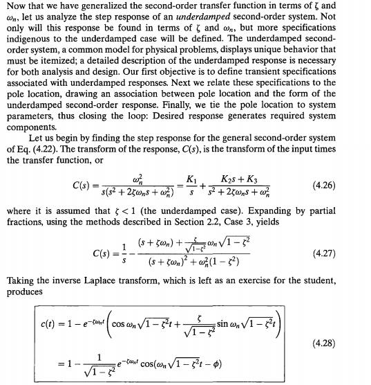
LECTURE FOUR Time Domain Analysis Transient and Steady-State Response Analysis
 LECTURE FOUR Time Domain Analysis Transient and Steady-State Response Analysis 4.1 Transient Response and Steady-State Response The time response of a control system consists of two parts: the transient
SYLLABUS. osmania university CHAPTER - 1 : CONTROL SYSTEMS CLASSIFICATION
 i SYLLABUS osmania university UNIT - I CHAPTER - 1 : CONTROL SYSTEMS CLASSIFICATION Open Loop and Closed Loop Systems, Mathematical Models and Transfer Functions from Governing Equations of Mechanical,
Advanced Servo Tuning
 Advanced Servo Tuning Dr. Rohan Munasinghe Department of Electronic and Telecommunication Engineering University of Moratuwa Servo System Elements position encoder Motion controller (software) Desired
Electrical Engineering. Control Systems. Comprehensive Theory with Solved Examples and Practice Questions. Publications
 Electrical Engineering Control Systems Comprehensive Theory with Solved Examples and Practice Questions Publications Publications MADE EASY Publications Corporate Office: 44-A/4, Kalu Sarai (Near Hauz
MCE441/541 Midterm Project Position Control of Rotary Servomechanism
 MCE441/541 Midterm Project Position Control of Rotary Servomechanism DUE: 11/08/2011 This project counts both as Homework 4 and 50 points of the second midterm exam 1 System Description A servomechanism
Andrea Zanchettin Automatic Control 1 AUTOMATIC CONTROL. Andrea M. Zanchettin, PhD Spring Semester, Linear control systems design
 Andrea Zanchettin Automatic Control 1 AUTOMATIC CONTROL Andrea M. Zanchettin, PhD Spring Semester, 2018 Linear control systems design Andrea Zanchettin Automatic Control 2 The control problem Let s introduce
CDS 101/110a: Lecture 8-1 Frequency Domain Design
 CDS 11/11a: Lecture 8-1 Frequency Domain Design Richard M. Murray 17 November 28 Goals: Describe canonical control design problem and standard performance measures Show how to use loop shaping to achieve
Position Control of DC Motor by Compensating Strategies
 Position Control of DC Motor by Compensating Strategies S Prem Kumar 1 J V Pavan Chand 1 B Pangedaiah 1 1. Assistant professor of Laki Reddy Balireddy College Of Engineering, Mylavaram Abstract - As the
[ á{tå TÄàt. Chapter Four. Time Domain Analysis of control system
 Chapter Four Time Domain Analysis of control system The time response of a control system consists of two parts: the transient response and the steady-state response. By transient response, we mean that
ME 375 System Modeling and Analysis
 ME 375 System Modeling and Analysis G(s) H(s) Section 9 Block Diagrams and Feedback Control Spring 2009 School of Mechanical Engineering Douglas E. Adams Associate Professor 9.1 Key Points to Remember
Chapter 10 Feedback ECE 3120 Microelectronics II Dr. Suketu Naik
 1 Chapter 10 Feedback Operational Amplifier Circuit Components 2 1. Ch 7: Current Mirrors and Biasing 2. Ch 9: Frequency Response 3. Ch 8: Active-Loaded Differential Pair 4. Ch 10: Feedback 5. Ch 11: Output
(1) Identify individual entries in a Control Loop Diagram. (2) Sketch Bode Plots by hand (when we could have used a computer
 Identify individual entries in a Control Loop Diagram. (2) Sketch Bode Plots by hand (when we could have used a computer") Last day: (1) Identify individual entries in a Control Loop Diagram (2) Sketch Bode Plots by hand (when we could have used a computer program to generate sketches). How might this be useful? Can more clearly
Last day: (1) Identify individual entries in a Control Loop Diagram (2) Sketch Bode Plots by hand (when we could have used a computer program to generate sketches). How might this be useful? Can more clearly
Classical Control Design Guidelines & Tools (L10.2) Transfer Functions
 Transfer Functions") Classical Control Design Guidelines & Tools (L10.2) Douglas G. MacMartin Summarize frequency domain control design guidelines and approach Dec 4, 2013 D. G. MacMartin CDS 110a, 2013 1 Transfer Functions
Classical Control Design Guidelines & Tools (L10.2) Douglas G. MacMartin Summarize frequency domain control design guidelines and approach Dec 4, 2013 D. G. MacMartin CDS 110a, 2013 1 Transfer Functions
Microelectronic Circuits - Fifth Edition Sedra/Smith Copyright 2004 by Oxford University Press, Inc.
 Feedback 1 Figure 8.1 General structure of the feedback amplifier. This is a signal-flow diagram, and the quantities x represent either voltage or current signals. 2 Figure E8.1 3 Figure 8.2 Illustrating
Bode and Log Magnitude Plots
 Bode and Log Magnitude Plots Bode Magnitude and Phase Plots System Gain and Phase Margins & Bandwidths Polar Plot and Bode Diagrams Transfer Function from Bode Plots Bode Plots of Open Loop and Closed
KINGS COLLEGE OF ENGINEERING DEPARTMENT OF ELECTRICAL AND ELECTRONICS ENGINEERING QUESTION BANK UNIT - I SYSTEMS AND THEIR REPRESENTATION
 KINGS COLLEGE OF ENGINEERING DEPARTMENT OF ELECTRICAL AND ELECTRONICS ENGINEERING QUESTION BANK NAME OF THE SUBJECT: EE 2253 CONTROL SYSTEMS YEAR / SEM: II / IV UNIT I SYSTEMS AND THEIR REPRESENTATION
Laboratory Assignment 5 Digital Velocity and Position control of a D.C. motor
 Laboratory Assignment 5 Digital Velocity and Position control of a D.C. motor 2.737 Mechatronics Dept. of Mechanical Engineering Massachusetts Institute of Technology Cambridge, MA0239 Topics Motor modeling
Foundations of Oscillator Circuit Design
 Foundations of Oscillator Circuit Design For a listing of recent titles in the Artech House Microwave Library, turn to the back of this book. Foundations of Oscillator Circuit Design Guillermo Gonzalez
1. Consider the closed loop system shown in the figure below. Select the appropriate option to implement the system shown in dotted lines using
 1. Consider the closed loop system shown in the figure below. Select the appropriate option to implement the system shown in dotted lines using op-amps a. b. c. d. Solution: b) Explanation: The dotted
Servo Tuning. Dr. Rohan Munasinghe Department. of Electronic and Telecommunication Engineering University of Moratuwa. Thanks to Dr.
 Servo Tuning Dr. Rohan Munasinghe Department. of Electronic and Telecommunication Engineering University of Moratuwa Thanks to Dr. Jacob Tal Overview Closed Loop Motion Control System Brain Brain Muscle
ME 5281 Fall Homework 8 Due: Wed. Nov. 4th; start of class.
 ME 5281 Fall 215 Homework 8 Due: Wed. Nov. 4th; start of class. Reading: Chapter 1 Part A: Warm Up Problems w/ Solutions (graded 4%): A.1 Non-Minimum Phase Consider the following variations of a system:
CDS 101/110: Lecture 8.2 PID Control
 CDS 11/11: Lecture 8.2 PID Control November 16, 216 Goals: Nyquist Example Introduce and review PID control. Show how to use loop shaping using PID to achieve a performance specification Discuss the use
LECTURE 2: PD, PID, and Feedback Compensation. ( ) = + We consider various settings for Zc when compensating the system with the following RL:
 = + We consider various settings for Zc when compensating the system with the following RL:") LECTURE 2: PD, PID, and Feedback Compensation. 2.1 Ideal Derivative Compensation (PD) Generally, we want to speed up the transient response (decrease Ts and Tp). If we are lucky then a system s desired
LECTURE 2: PD, PID, and Feedback Compensation. 2.1 Ideal Derivative Compensation (PD) Generally, we want to speed up the transient response (decrease Ts and Tp). If we are lucky then a system s desired
Lecture 5 Introduction to control
 Lecture 5 Introduction to control Feedback control is a way of automatically adjusting a variable to a desired value despite possible external influence or variations. Eg: Heating your house. No feedback
Pole, zero and Bode plot
 Pole, zero and Bode plot EC04 305 Lecture notes YESAREKEY December 12, 2007 Authored by: Ramesh.K Pole, zero and Bode plot EC04 305 Lecture notes A rational transfer function H (S) can be expressed as
Magnetic Levitation System
 Magnetic Levitation System Electromagnet Infrared LED Phototransistor Levitated Ball Magnetic Levitation System K. Craig 1 Magnetic Levitation System Electromagnet Emitter Infrared LED i Detector Phototransistor
Compensation of a position servo
 UPPSALA UNIVERSITY SYSTEMS AND CONTROL GROUP CFL & BC 9610, 9711 HN & PSA 9807, AR 0412, AR 0510, HN 2006-08 Automatic Control Compensation of a position servo Abstract The angular position of the shaft
Testing Power Sources for Stability
 Keywords Venable, frequency response analyzer, oscillator, power source, stability testing, feedback loop, error amplifier compensation, impedance, output voltage, transfer function, gain crossover, bode
CDS 101/110: Lecture 9.1 Frequency DomainLoop Shaping
 CDS /: Lecture 9. Frequency DomainLoop Shaping November 3, 6 Goals: Review Basic Loop Shaping Concepts Work through example(s) Reading: Åström and Murray, Feedback Systems -e, Section.,.-.4,.6 I.e., we
Lecture 7:Examples using compensators
 Lecture :Examples using compensators Venkata Sonti Department of Mechanical Engineering Indian Institute of Science Bangalore, India, This draft: March, 8 Example :Spring Mass Damper with step input Consider
EES42042 Fundamental of Control Systems Bode Plots
 EES42042 Fundamental of Control Systems Bode Plots DR. Ir. Wahidin Wahab M.Sc. Ir. Aries Subiantoro M.Sc. 2 Bode Plots Plot of db Gain and phase vs frequency It is assumed you know how to construct Bode
Design of Compensator for Dynamical System
 Design of Compensator for Dynamical System Ms.Saroja S. Chavan PimpriChinchwad College of Engineering, Pune Prof. A. B. Patil PimpriChinchwad College of Engineering, Pune ABSTRACT New applications of dynamical
EE 435. Lecture 16. Compensation Systematic Two-Stage Op Amp Design
 EE 435 Lecture 16 Compensation Systematic Two-Stage Op Amp Design Review from last lecture Review of Basic Concepts Pole Locations and Stability Theorem: A system is stable iff all closed-loop poles lie
LINEAR MODELING OF A SELF-OSCILLATING PWM CONTROL LOOP
 Carl Sawtell June 2012 LINEAR MODELING OF A SELF-OSCILLATING PWM CONTROL LOOP There are well established methods of creating linearized versions of PWM control loops to analyze stability and to create
Testing and Stabilizing Feedback Loops in Today s Power Supplies
 Keywords Venable, frequency response analyzer, impedance, injection transformer, oscillator, feedback loop, Bode Plot, power supply design, open loop transfer function, voltage loop gain, error amplifier,
Cantonment, Dhaka-1216, BANGLADESH
 International Conference on Mechanical, Industrial and Energy Engineering 2014 26-27 December, 2014, Khulna, BANGLADESH ICMIEE-PI-140153 Electro-Mechanical Modeling of Separately Excited DC Motor & Performance
CONTROLLER DESIGN FOR POWER CONVERSION SYSTEMS
 CONTROLLER DESIGN FOR POWER CONVERSION SYSTEMS Introduction A typical feedback system found in power converters Switched-mode power converters generally use PI, pz, or pz feedback compensators to regulate
Fundamentals of Servo Motion Control
 Fundamentals of Servo Motion Control The fundamental concepts of servo motion control have not changed significantly in the last 50 years. The basic reasons for using servo systems in contrast to open
DEGREE: Biomedical Engineering YEAR: TERM: 1
 COURSE: Control Engineering DEGREE: Biomedical Engineering YEAR: TERM: 1 La asignatura tiene 14 sesiones que se distribuyen a lo largo de 7 semanas. Los dos laboratorios puede situarse en cualquiera de
EE 3TP4: Signals and Systems Lab 5: Control of a Servomechanism
 EE 3TP4: Signals and Systems Lab 5: Control of a Servomechanism Tim Davidson Ext. 27352 davidson@mcmaster.ca Objective To identify the plant model of a servomechanism, and explore the trade-off between
A Machine Tool Controller using Cascaded Servo Loops and Multiple Feedback Sensors per Axis
 A Machine Tool Controller using Cascaded Servo Loops and Multiple Sensors per Axis David J. Hopkins, Timm A. Wulff, George F. Weinert Lawrence Livermore National Laboratory 7000 East Ave, L-792, Livermore,
TUTORIAL 9 OPEN AND CLOSED LOOP LINKS. On completion of this tutorial, you should be able to do the following.
 TUTORIAL 9 OPEN AND CLOSED LOOP LINKS This tutorial is of interest to any student studying control systems and in particular the EC module D7 Control System Engineering. On completion of this tutorial,
Introduction to Signals and Systems Lecture #9 - Frequency Response. Guillaume Drion Academic year
 Introduction to Signals and Systems Lecture #9 - Frequency Response Guillaume Drion Academic year 2017-2018 1 Transmission of complex exponentials through LTI systems Continuous case: LTI system where
CDS 101/110a: Lecture 8-1 Frequency Domain Design. Frequency Domain Performance Specifications
 CDS /a: Lecture 8- Frequency Domain Design Richard M. Murray 7 November 28 Goals:! Describe canonical control design problem and standard performance measures! Show how to use loop shaping to achieve a
Optimal Control System Design
 Chapter 6 Optimal Control System Design 6.1 INTRODUCTION The active AFO consists of sensor unit, control system and an actuator. While designing the control system for an AFO, a trade-off between the transient
Experiment 9. PID Controller
 Experiment 9 PID Controller Objective: - To be familiar with PID controller. - Noting how changing PID controller parameter effect on system response. Theory: The basic function of a controller is to execute
This manuscript was the basis for the article A Refresher Course in Control Theory printed in Machine Design, September 9, 1999.
 This manuscript was the basis for the article A Refresher Course in Control Theory printed in Machine Design, September 9, 1999. Use Control Theory to Improve Servo Performance George Ellis Introduction
Lab 1: Simulating Control Systems with Simulink and MATLAB
 Lab 1: Simulating Control Systems with Simulink and MATLAB EE128: Feedback Control Systems Fall, 2006 1 Simulink Basics Simulink is a graphical tool that allows us to simulate feedback control systems.
of harmonic cancellation algorithms The internal model principle enable precision motion control Dynamic control
 Dynamic control Harmonic cancellation algorithms enable precision motion control The internal model principle is a 30-years-young idea that serves as the basis for a myriad of modern motion control approaches.
Comparative Analysis of a PID Controller using Ziegler- Nichols and Auto Turning Method
 International Academic Institute for Science and Technology International Academic Journal of Science and Engineering Vol. 3, No. 10, 2016, pp. 1-16. ISSN 2454-3896 International Academic Journal of Science
Loop Design. Chapter Introduction
 Chapter 8 Loop Design 8.1 Introduction This is the first Chapter that deals with design and we will therefore start by some general aspects on design of engineering systems. Design is complicated because
Communication Engineering Prof. Surendra Prasad Department of Electrical Engineering Indian Institute of Technology, Delhi
 Communication Engineering Prof. Surendra Prasad Department of Electrical Engineering Indian Institute of Technology, Delhi Lecture - 23 The Phase Locked Loop (Contd.) We will now continue our discussion
Experiment 1: Amplifier Characterization Spring 2019
 Experiment 1: Amplifier Characterization Spring 2019 Objective: The objective of this experiment is to develop methods for characterizing key properties of operational amplifiers Note: We will be using
Design and Implementation of the Control System for a 2 khz Rotary Fast Tool Servo
 Design and Implementation of the Control System for a 2 khz Rotary Fast Tool Servo Richard C. Montesanti a,b, David L. Trumper b a Lawrence Livermore National Laboratory, Livermore, CA b Massachusetts
CHASSIS DYNAMOMETER TORQUE CONTROL SYSTEM DESIGN BY DIRECT INVERSE COMPENSATION. C.Matthews, P.Dickinson, A.T.Shenton
 CHASSIS DYNAMOMETER TORQUE CONTROL SYSTEM DESIGN BY DIRECT INVERSE COMPENSATION C.Matthews, P.Dickinson, A.T.Shenton Department of Engineering, The University of Liverpool, Liverpool L69 3GH, UK Abstract:
1. To study the influence of the gain on the transient response of a position servo. 2. To study the effect of velocity feedback.
 KING FAHD UNIVERSITY OF PETROLEUM & MINERALS Electrical Engineering Department EE 380 - Control Engineering Experiment # 6 Servo Motor Position Control Using a Proportional Controller OBJECTIVES: 1. To
SECTION 6: ROOT LOCUS DESIGN
 SECTION 6: ROOT LOCUS DESIGN MAE 4421 Control of Aerospace & Mechanical Systems 2 Introduction Introduction 3 Consider the following unity feedback system 3 433 Assume A proportional controller Design
ADJUSTING SERVO DRIVE COMPENSATION George W. Younkin, P.E. Life Fellow IEEE Industrial Controls Research, Inc. Fond du Lac, Wisconsin
 ADJUSTING SERVO DRIVE COMPENSATION George W. Younkin, P.E. Life Fello IEEE Industrial Controls Research, Inc. Fond du Lac, Wisconsin All industrial servo drives require some form of compensation often
Course Outline. Time vs. Freq. Domain Analysis. Frequency Response. Amme 3500 : System Dynamics & Control. Design via Frequency Response
 Course Outline Amme 35 : System Dynamics & Control Design via Frequency Response Week Date Content Assignment Notes Mar Introduction 2 8 Mar Frequency Domain Modelling 3 5 Mar Transient Performance and
CHAPTER 4 PID CONTROLLER BASED SPEED CONTROL OF THREE PHASE INDUCTION MOTOR
 36 CHAPTER 4 PID CONTROLLER BASED SPEED CONTROL OF THREE PHASE INDUCTION MOTOR 4.1 INTRODUCTION Now a day, a number of different controllers are used in the industry and in many other fields. In a quite
Phys Lecture 5. Motors
 Phys 253 Lecture 5 1. Get ready for Design Reviews Next Week!! 2. Comments on Motor Selection 3. Introduction to Control (Lab 5 Servo Motor) Different performance specifications for all 4 DC motors supplied
1. A. AC SERVO MOTOR
 TITLE: STUDY OF AC SERVOMOTOR GPREC/DEEE/EXPT-CSAP-1-A 1. A. AC SERVO MOTOR AIM: To study speed-torque characteristics of an AC servo motor APPRATUS: AC Servomotor and Digital Multimeter THEORY: Most of
Bode Plots. Hamid Roozbahani
 Bode Plots Hamid Roozbahani A Bode plot is a graph of the transfer function of a linear, time-invariant system versus frequency, plotted with a logfrequency axis, to show the system's frequency response.
Advanced Motion Control Optimizes Laser Micro-Drilling
 Advanced Motion Control Optimizes Laser Micro-Drilling The following discussion will focus on how to implement advanced motion control technology to improve the performance of laser micro-drilling machines.
Lecture 10. Lab next week: Agenda: Control design fundamentals. Proportional Control Proportional-Integral Control
 264 Lab next week: Lecture 10 Lab 17: Proportional Control Lab 18: Proportional-Integral Control (1/2) Agenda: Control design fundamentals Objectives (Tracking, disturbance/noise rejection, robustness)
Rotary Motion Servo Plant: SRV02. Rotary Experiment #03: Speed Control. SRV02 Speed Control using QuaRC. Student Manual
 Rotary Motion Servo Plant: SRV02 Rotary Experiment #03: Speed Control SRV02 Speed Control using QuaRC Student Manual Table of Contents 1. INTRODUCTION...1 2. PREREQUISITES...1 3. OVERVIEW OF FILES...2
Dr Ian R. Manchester Dr Ian R. Manchester Amme 3500 : Root Locus Design
 Week Content Notes 1 Introduction 2 Frequency Domain Modelling 3 Transient Performance and the s-plane 4 Block Diagrams 5 Feedback System Characteristics Assign 1 Due 6 Root Locus 7 Root Locus 2 Assign
Chapter 5 Frequency-domain design
 Chapter 5 Frequency-domain design Control Automático 3º Curso. Ing. Industrial Escuela Técnica Superior de Ingenieros Universidad de Sevilla Outline of the presentation Introduction. Time response analysis
Motor Control. Suppose we wish to use a microprocessor to control a motor - (or to control the load attached to the motor!) Power supply.
 Power supply.") Motor Control Suppose we wish to use a microprocessor to control a motor - (or to control the load attached to the motor!) Operator Input CPU digital? D/A, PWM analog voltage Power supply Amplifier linear,
Motor Control Suppose we wish to use a microprocessor to control a motor - (or to control the load attached to the motor!) Operator Input CPU digital? D/A, PWM analog voltage Power supply Amplifier linear,
Servo Tuning Tutorial
 Servo Tuning Tutorial 1 Presentation Outline Introduction Servo system defined Why does a servo system need to be tuned Trajectory generator and velocity profiles The PID Filter Proportional gain Derivative
EVALUATION ALGORITHM- BASED ON PID CONTROLLER DESIGN FOR THE UNSTABLE SYSTEMS
 EVALUATION ALGORITHM- BASED ON PID CONTROLLER DESIGN FOR THE UNSTABLE SYSTEMS Erliza Binti Serri 1, Wan Ismail Ibrahim 1 and Mohd Riduwan Ghazali 2 1 Sustanable Energy & Power Electronics Research, FKEE
Specify Gain and Phase Margins on All Your Loops
 Keywords Venable, frequency response analyzer, power supply, gain and phase margins, feedback loop, open-loop gain, output capacitance, stability margins, oscillator, power electronics circuits, voltmeter,
CHAPTER 11. Feedback. Microelectronic Circuits, Seventh Edition. Copyright 2015 by Oxford University Press
 CHAPTER 11 Feedback Figure 11.1 General structure of the feedback amplifier. This is a signal-flow diagram, and the quantities x represent either voltage or current signals. Figure 11.2 Determining the
This article presents a review of PLL transfer functions with attention to the conditions required for steady-state stability
 Phase Lock Loop Stability Analysis This article presents a review of PLL transfer functions with attention to the conditions required for steadystate stability By Arun Mansukhani Motorola, Inc. P hase
Control Design for Servomechanisms July 2005, Glasgow Detailed Training Course Agenda
 Control Design for Servomechanisms 12 14 July 2005, Glasgow Detailed Training Course Agenda DAY 1 INTRODUCTION TO SYSTEMS AND MODELLING 9.00 Introduction The Need For Control - What Is Control? - Feedback
Advanced Motion Control Optimizes Mechanical Micro-Drilling
 Advanced Motion Control Optimizes Mechanical Micro-Drilling The following discussion will focus on how to implement advanced motion control technology to improve the performance of mechanical micro-drilling
DEPARTMENT OF ELECTRICAL & ELECTRONICS ENGINEERING Accredited by NBA, New Delhi for 3 years:26/7/18 to 30/6/21 2 nd ASSIGNMENT
 DAYANANDA SAGAR ACADEMY OF TECHNOLOGY AND MANAGEMENT (Affiliated to Visvesvaraya Technological University,Belagavi & Approved by AICTE,New Delhi) Udayapura, Kanakapura Road, Opp: Art of Living, BANGALORE
EE422G Solution to Homework #8
 EE4G Solution to Homework #8. MATLAB >> H = tf([ 4],[ 6 6]); >> H = tf([ ],[ - 5 5 4]); >> step(h).7 Step Response.6.5 Amplitude.4... 4 5 6 >> step(h) Time (sec).5 Step Response.5 Amplitude.5.5.5..5..5..5.4.45