PERSONALIZED EXPERIMENTATION IN CLASSICAL CONTROLS WITH MATLAB REAL TIME WINDOWS TARGET AND PORTABLE AEROPENDULUM KIT
|
|
|
- Opal Marion Bates
- 5 years ago
- Views:
Transcription
1 Eniko T. Enikov, University of Arizona Estelle Eke, California State University Sacramento PERSONALIZED EXPERIMENTATION IN CLASSICAL CONTROLS WITH MATLAB REAL TIME WINDOWS TARGET AND PORTABLE AEROPENDULUM KIT

2 Outline Motivation The Aeropendulum Apparatus Real-Time vs. Soft Real Time Student Design Activities Plant modeling, parameter identification, identification of non-linearities Feedback linearization, steady-state error and system types parameter identification Matlab's pem() prediction-error minimization function (time permitting) closed-loop control experiments: proportional, phase lag, phase lead and on/off (bang-bang) control (time permitting) Results from implementation at CSUS and Univ. of Arizona

3 Motivation Develop an portable lowcost apparatus that illustrates classical control systems course with a hands-on experimentation. Eliminate the need for lab space, teaching assistant. Provide a quick pathway from controller design to implementation for mechanical engineering students.

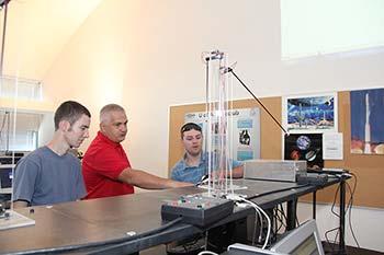
4 Experimental Apparatus Acrylic stand Pendulum with angle sensing potentiometer, DC-motor and propeller Target circuit board driving the propeller with different PWM ratios in forward and reverse direction MATLAB Simulink Real Time Windows Target GUI for controller implementation
5 Data Flow Diagram
6 Real Time Windows Target Environment
7 Modeling Tasks

8 Experiment 1: Parameter Extraction Using the steady-state response, find the parameters K/mg
9 Challenge 1: Dealing with Dead Zone
10 Challenge II: Feedback Linearization Result Type 1 System
11 Experiment II: Weightless Pendulum (K=0)
12 Experiment III: Parameter Identification (Kp=1)
13 Challenge III: Stability and Root Locus. What is wrong? Kp>3 (unstable)
14 Model Correction: Motor Dynamics

15 Experiment IV: Controller Design Using Bode Plots
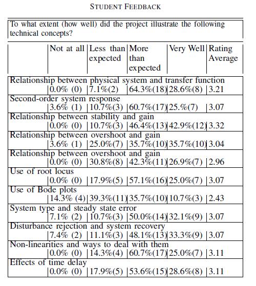
16 Evaluation
17 Hands-On Activities Open Loop Response
18 plot(t,theta,t,pwm); grid minor PWM
19 Gather Data u_ss=[ ]; theta_ss=[ ]; sine_ss=sind(theta_ss); plot(sine_ss,u_ss) ylabel('pwm Input') xlabel('sin theta_{ss}')
20 Steady State Data PWM Input SIN theta ss
21 Fit a Line on Points 3-13 P=polyfit(sine_ss(3:13),u_ss(3:13),1) ; plot(sine_ss,u_ss,sine_ss(3:13), polyval(p,sine_ss(3:13))) shg legend('experiment', 'Linear fit')
22 Slope and Offset P = Experiment Linear fit X: 0 Y:


23 Project Installment # 2 Update Model mg S K u u0=24 Slope=92.5
24 Test Using Closed Loop with Zero Gain (Slope needs adjustment, c. a 80)
25 Check System Type using Kp=1 Theta=30
26 plot(t,theta) degrees error (linearization Is not perfect)
27 Identify Parameters From the response extract approximate values for and, then calculate and. (Use formulas for overshoot, peak time, rise time etc. to find and and then related to the physical parameters). The plot achieved for proportional controller may produce an over-damped relation in which case you will not be able to find out the parameters by using the above formulas. Just try increasing the proportional gain K p to the point when you start getting an overshoot.
exp(-pi*x/sqrt(1-x^2))-0.5,0) zeta=0.")
28 Using Kp= Tr=0.4 sec=>wn=4.5 PO=(48-32)/32=50% K/mL=4.5^2/Kp=10 c/ml^2=2*dzeta*wn/kp= sec Matlab for Damping > zeta=fzero(@(x)exp(-pi*x/sqrt(1-x^2))-0.5,0) zeta=0.22
![System Identified g=tf(10,[1 0.97 0]) 10 +0.97 0.4 Root Locus 0.](/docs-images/94/120040402/images/29-2.jpg "3 Imaginary Axis (seconds -1 ) 0.2 0.1 0-0.1-0.2-0.3-0.4-1 -0.8-0.6-0.4-0.2 0 0.2 0.4 Real Axis (seconds -1 )")
29 System Identified g=tf(10,[ ]) Root Locus 0.3 Imaginary Axis (seconds -1 ) Real Axis (seconds -1 )
30 Test Stability with Kp=1, 2, 3 Kp=2.4 ->stability limit
31 Modify The Model Kp ( s s) 1 s 3 Root Locus g=tf(10,conv([ ],[1 4.5])) rlocus(g) Imaginary Axis (seconds -1 ) System: g Gain: 2.3 Pole: i Damping: Overshoot (%): 98 Frequency (rad/s): Real Axis (seconds -1 )
32 Adjust for Steady State Error Kp 10 2 ( s 0.97s) s Kp 10 2 ( s 0.97s b) s 1 e ss 10 1 b b
33 Lag Compensator s z s p 10 2 ( s 0.97s 2) s Imaginary Axis (seconds -1 ) s 5 s 1 Root Locus System: untitled1 Gain: 0.46 Pole: i Damping: Overshoot (%): 117 Frequency (rad/s): 1.81 Imaginary Axis (seconds -1 ) s 0.5 s 0.1 Root Locus System: untitled1 Gain: 1.34 Pole: i Damping: Overshoot (%): 88 Frequency (rad/s): Real Axis (seconds -1 ) Real Axis (seconds -1 )
34 Step Response of Lag Compensation X: Y: 30.8 c=tf([1.5],[1.1]) clagd=c2d(c,0.01)
35 Prof. Eke s Slides on Implementation
36 Optional Activities Lead Compensator Lead-Lag Compensator On/Off Controller
Readings: FC: p : lead compensation. 9/9/2011 Classical Control 1
 MM0 Frequency Response Design Readings: FC: p389-407: lead compensation 9/9/20 Classical Control What Have We Talked about in MM9? Control design based on Bode plot Stability margins (Gain margin and phase
Frequency Response Analysis and Design Tutorial
 1 of 13 1/11/2011 5:43 PM Frequency Response Analysis and Design Tutorial I. Bode plots [ Gain and phase margin Bandwidth frequency Closed loop response ] II. The Nyquist diagram [ Closed loop stability
CDS 101/110: Lecture 8.2 PID Control
 CDS 11/11: Lecture 8.2 PID Control November 16, 216 Goals: Nyquist Example Introduce and review PID control. Show how to use loop shaping using PID to achieve a performance specification Discuss the use
Outline. Digital Control. Lecture 3
 Outline Outline Outline 1 ler Design 2 What have we talked about in MM2? Sampling rate selection Equivalents between continuous & digital Systems Outline ler Design Emulation Method for 1 ler Design
GE420 Laboratory Assignment 8 Positioning Control of a Motor Using PD, PID, and Hybrid Control
 GE420 Laboratory Assignment 8 Positioning Control of a Motor Using PD, PID, and Hybrid Control Goals for this Lab Assignment: 1. Design a PD discrete control algorithm to allow the closed-loop combination
MEM 01 DC MOTOR-BASED SERVOMECHANISM WITH TACHOMETER FEEDBACK
 MEM 01 DC MOTOR-BASED SERVOMECHANISM WITH TACHOMETER FEEDBACK Motivation Closing a feedback loop around a DC motor to obtain motor shaft position that is proportional to a varying electrical signal is
Dr Ian R. Manchester Dr Ian R. Manchester Amme 3500 : Root Locus Design
 Week Content Notes 1 Introduction 2 Frequency Domain Modelling 3 Transient Performance and the s-plane 4 Block Diagrams 5 Feedback System Characteristics Assign 1 Due 6 Root Locus 7 Root Locus 2 Assign
Hands-on Lab. PID Closed-Loop Control
 Hands-on Lab PID Closed-Loop Control Adding feedback improves performance. Unity feedback was examined to serve as a motivating example. Lectures derived the power of adding proportional, integral and
ME 5281 Fall Homework 8 Due: Wed. Nov. 4th; start of class.
 ME 5281 Fall 215 Homework 8 Due: Wed. Nov. 4th; start of class. Reading: Chapter 1 Part A: Warm Up Problems w/ Solutions (graded 4%): A.1 Non-Minimum Phase Consider the following variations of a system:
Control Design for Servomechanisms July 2005, Glasgow Detailed Training Course Agenda
 Control Design for Servomechanisms 12 14 July 2005, Glasgow Detailed Training Course Agenda DAY 1 INTRODUCTION TO SYSTEMS AND MODELLING 9.00 Introduction The Need For Control - What Is Control? - Feedback
MEM01: DC-Motor Servomechanism
 MEM01: DC-Motor Servomechanism Interdisciplinary Automatic Controls Laboratory - ME/ECE/CHE 389 February 5, 2016 Contents 1 Introduction and Goals 1 2 Description 2 3 Modeling 2 4 Lab Objective 5 5 Model
Course Outline. Time vs. Freq. Domain Analysis. Frequency Response. Amme 3500 : System Dynamics & Control. Design via Frequency Response
 Course Outline Amme 35 : System Dynamics & Control Design via Frequency Response Week Date Content Assignment Notes Mar Introduction 2 8 Mar Frequency Domain Modelling 3 5 Mar Transient Performance and
5 Lab 5: Position Control Systems - Week 2
 5 Lab 5: Position Control Systems - Week 2 5.7 Introduction In this lab, you will convert the DC motor to an electromechanical positioning actuator by properly designing and implementing a proportional
Bode Plot for Controller Design
 Bode Plot for Controller Design Dr. Bishakh Bhattacharya Professor, Department of Mechanical Engineering IIT Kanpur Joint Initiative of IITs and IISc - Funded by This Lecture Contains Bode Plot for Controller
Lecture 7:Examples using compensators
 Lecture :Examples using compensators Venkata Sonti Department of Mechanical Engineering Indian Institute of Science Bangalore, India, This draft: March, 8 Example :Spring Mass Damper with step input Consider
Position Control of DC Motor by Compensating Strategies
 Position Control of DC Motor by Compensating Strategies S Prem Kumar 1 J V Pavan Chand 1 B Pangedaiah 1 1. Assistant professor of Laki Reddy Balireddy College Of Engineering, Mylavaram Abstract - As the
JUNE 2014 Solved Question Paper
 JUNE 2014 Solved Question Paper 1 a: Explain with examples open loop and closed loop control systems. List merits and demerits of both. Jun. 2014, 10 Marks Open & Closed Loop System - Advantages & Disadvantages
Root Locus Design. by Martin Hagan revised by Trevor Eckert 1 OBJECTIVE
 TAKE HOME LABS OKLAHOMA STATE UNIVERSITY Root Locus Design by Martin Hagan revised by Trevor Eckert 1 OBJECTIVE The objective of this experiment is to design a feedback control system for a motor positioning
ME451: Control Systems. Course roadmap
 ME451: Control Systems Lecture 20 Root locus: Lead compensator design Dr. Jongeun Choi Department of Mechanical Engineering Michigan State University Fall 2008 1 Modeling Course roadmap Analysis Design
Addendum Handout for the ECE3510 Project. The magnetic levitation system that is provided for this lab is a non-linear system.
 Addendum Handout for the ECE3510 Project The magnetic levitation system that is provided for this lab is a non-linear system. Because of this fact, it should be noted that the associated ideal linear responses
Design of Compensator for Dynamical System
 Design of Compensator for Dynamical System Ms.Saroja S. Chavan PimpriChinchwad College of Engineering, Pune Prof. A. B. Patil PimpriChinchwad College of Engineering, Pune ABSTRACT New applications of dynamical
Automatic Control Systems 2017 Spring Semester
 Automatic Control Systems 2017 Spring Semester Assignment Set 1 Dr. Kalyana C. Veluvolu Deadline: 11-APR - 16:00 hours @ IT1-815 1) Find the transfer function / for the following system using block diagram
EE 308 Spring Preparation for Final Lab Project Simple Motor Control. Motor Control
 Preparation for Final Lab Project Simple Motor Control Motor Control A proportional integral derivative controller (PID controller) is a generic control loop feedback mechanism (controller) widely used
MTE 360 Automatic Control Systems University of Waterloo, Department of Mechanical & Mechatronics Engineering
 MTE 36 Automatic Control Systems University of Waterloo, Department of Mechanical & Mechatronics Engineering Laboratory #1: Introduction to Control Engineering In this laboratory, you will become familiar
Ver. 4/5/2002, 1:11 PM 1
 Mechatronics II Laboratory Exercise 6 PID Design The purpose of this exercise is to study the effects of a PID controller on a motor-load system. Although not a second-order system, a PID controlled motor-load
Experiment 9. PID Controller
 Experiment 9 PID Controller Objective: - To be familiar with PID controller. - Noting how changing PID controller parameter effect on system response. Theory: The basic function of a controller is to execute
ME375 Lab Project. Bradley Boane & Jeremy Bourque April 25, 2018
 ME375 Lab Project Bradley Boane & Jeremy Bourque April 25, 2018 Introduction: The goal of this project was to build and program a two-wheel robot that travels forward in a straight line for a distance
EE 482 : CONTROL SYSTEMS Lab Manual
 University of Bahrain College of Engineering Dept. of Electrical and Electronics Engineering EE 482 : CONTROL SYSTEMS Lab Manual Dr. Ebrahim Al-Gallaf Assistance Professor of Intelligent Control and Robotics
Dr Ian R. Manchester
 Week Content Notes 1 Introduction 2 Frequency Domain Modelling 3 Transient Performance and the s-plane 4 Block Diagrams 5 Feedback System Characteristics Assign 1 Due 6 Root Locus 7 Root Locus 2 Assign
ME 375 System Modeling and Analysis
 ME 375 System Modeling and Analysis G(s) H(s) Section 9 Block Diagrams and Feedback Control Spring 2009 School of Mechanical Engineering Douglas E. Adams Associate Professor 9.1 Key Points to Remember
Low-Cost hardware connectivity with Simulink MATLAB-Day RWTH Aachen Sebastian Groß October 24th, 2013
 Low-Cost hardware connectivity with Simulink MATLAB-Day RWTH Aachen Sebastian Groß October 24th, 2013 2013 The MathWorks, Inc. 1 LEGO Mindstorms NXT: a first demo EDUCON 2013, Berlin, Germany 2 A first
Electrical Engineering. Control Systems. Comprehensive Theory with Solved Examples and Practice Questions. Publications
 Electrical Engineering Control Systems Comprehensive Theory with Solved Examples and Practice Questions Publications Publications MADE EASY Publications Corporate Office: 44-A/4, Kalu Sarai (Near Hauz
Closed Loop Magnetic Levitation Control of a Rotary Inductrack System. Senior Project Proposal. Students: Austin Collins Corey West
 Closed Loop Magnetic Levitation Control of a Rotary Inductrack System Senior Project Proposal Students: Austin Collins Corey West Advisors: Dr. Winfred Anakwa Mr. Steven Gutschlag Date: December 18, 2013
MCE441/541 Midterm Project Position Control of Rotary Servomechanism
 MCE441/541 Midterm Project Position Control of Rotary Servomechanism DUE: 11/08/2011 This project counts both as Homework 4 and 50 points of the second midterm exam 1 System Description A servomechanism
EC CONTROL SYSTEMS ENGINEERING
 1 YEAR / SEM: II / IV EC 1256. CONTROL SYSTEMS ENGINEERING UNIT I CONTROL SYSTEM MODELING PART-A 1. Define open loop and closed loop systems. 2. Define signal flow graph. 3. List the force-voltage analogous
Rotary Motion Servo Plant: SRV02. Rotary Experiment #03: Speed Control. SRV02 Speed Control using QuaRC. Student Manual
 Rotary Motion Servo Plant: SRV02 Rotary Experiment #03: Speed Control SRV02 Speed Control using QuaRC Student Manual Table of Contents 1. INTRODUCTION...1 2. PREREQUISITES...1 3. OVERVIEW OF FILES...2
BSNL TTA Question Paper Control Systems Specialization 2007
 BSNL TTA Question Paper Control Systems Specialization 2007 1. An open loop control system has its (a) control action independent of the output or desired quantity (b) controlling action, depending upon
Module 08 Controller Designs: Compensators and PIDs
 Module 08 Controller Designs: Compensators and PIDs Ahmad F. Taha EE 3413: Analysis and Desgin of Control Systems Email: ahmad.taha@utsa.edu Webpage: http://engineering.utsa.edu/ taha March 31, 2016 Ahmad
Magnetic Levitation System
 Magnetic Levitation System Electromagnet Infrared LED Phototransistor Levitated Ball Magnetic Levitation System K. Craig 1 Magnetic Levitation System Electromagnet Emitter Infrared LED i Detector Phototransistor
LECTURE 2: PD, PID, and Feedback Compensation. ( ) = + We consider various settings for Zc when compensating the system with the following RL:
 = + We consider various settings for Zc when compensating the system with the following RL:") LECTURE 2: PD, PID, and Feedback Compensation. 2.1 Ideal Derivative Compensation (PD) Generally, we want to speed up the transient response (decrease Ts and Tp). If we are lucky then a system s desired
LECTURE 2: PD, PID, and Feedback Compensation. 2.1 Ideal Derivative Compensation (PD) Generally, we want to speed up the transient response (decrease Ts and Tp). If we are lucky then a system s desired
Pan-Tilt Signature System
 Pan-Tilt Signature System Pan-Tilt Signature System Rob Gillette Matt Cieloszyk Luke Bowen Final Presentation Introduction Problem Statement: We proposed to build a device that would mimic human script
The Discussion of this exercise covers the following points: Angular position control block diagram and fundamentals. Power amplifier 0.
 Exercise 6 Motor Shaft Angular Position Control EXERCISE OBJECTIVE When you have completed this exercise, you will be able to associate the pulses generated by a position sensing incremental encoder with
Industrial Control Equipment. ACS-1000 Analog Control System
 Analog Control System, covered with many technical disciplines, explicates the central significance of Analog Control System. This applies particularly in mechanical and electrical engineering, and as
AC : A STUDENT-ORIENTED CONTROL LABORATORY US- ING PROGRAM CC
 AC 2011-490: A STUDENT-ORIENTED CONTROL LABORATORY US- ING PROGRAM CC Ziqian Liu, SUNY Maritime College Ziqian Liu received the Ph.D. degree from the Southern Illinois University Carbondale in 2005. He
Laboratory PID Tuning Based On Frequency Response Analysis. 2. be able to evaluate system performance for empirical tuning method;
 Laboratory PID Tuning Based On Frequency Response Analysis Objectives: At the end, student should 1. appreciate a systematic way of tuning PID loop by the use of process frequency response analysis; 2.
AERATOR MIXING STATION
 AERATOR MIXING STATION Green Team: Marc Labrie Matt Baltimore Michael Newman Michael Sherrit University of Tennessee at Chattanooga April 13, 211 ENGR 328L OVERVIEW System Overview SSOC Analysis Step Response
Optimal Control System Design
 Chapter 6 Optimal Control System Design 6.1 INTRODUCTION The active AFO consists of sensor unit, control system and an actuator. While designing the control system for an AFO, a trade-off between the transient
University of Tennessee at Chattanooga. Step Response Modeling. Control Systems Laboratory
 University of Tennessee at Chattanooga Step Response Modeling Control Systems Laboratory By Stephen Rue Tan Team (Stephanie Raulston, Stefan Hanley) Course: ENGR 3280L Section: 000 Date: 03/06/2013 Instructor:
JNTUWORLD. 6 The unity feedback system whose open loop transfer function is given by G(s)=K/s(s 2 +6s+10) Determine: (i) Angles of asymptotes *****
=K/s(s 2 +6s+10) Determine: (i) Angles of asymptotes *****") Code: 9A050 III B. Tech I Semester (R09) Regular Eaminations, November 0 Time: hours Ma Marks: 70 (a) What is a mathematical model of a physical system? Eplain briefly. (b) Write the differential equations
Code: 9A050 III B. Tech I Semester (R09) Regular Eaminations, November 0 Time: hours Ma Marks: 70 (a) What is a mathematical model of a physical system? Eplain briefly. (b) Write the differential equations
Lab Report 4: Root Locus and Proportional Controller
 Lab Report 4: Root Locus and Proportional Controller University of Tennessee at Chattanooga Engineering 32 Blue Team Kevin Schrumpf Justin Anchanattu Justin Rehagen April 1, 212 Introduction The first
GE 320: Introduction to Control Systems
 GE 320: Introduction to Control Systems Laboratory Section Manual 1 Welcome to GE 320.. 1 www.softbankrobotics.com 1 1 Introduction This section summarizes the course content and outlines the general procedure
Design of a Simulink-Based Control Workstation for Mobile Wheeled Vehicles with Variable-Velocity Differential Motor Drives
 Design of a Simulink-Based Control Workstation for Mobile Wheeled Vehicles with Variable-Velocity Differential Motor Drives Kevin Block, Timothy De Pasion, Benjamin Roos, Alexander Schmidt Gary Dempsey
Figure 1.1: Quanser Driving Simulator
 1 INTRODUCTION The Quanser HIL Driving Simulator (QDS) is a modular and expandable LabVIEW model of a car driving on a closed track. The model is intended as a platform for the development, implementation
ANNA UNIVERSITY :: CHENNAI MODEL QUESTION PAPER(V-SEMESTER) B.E. ELECTRONICS AND COMMUNICATION ENGINEERING EC334 - CONTROL SYSTEMS
 B.E. ELECTRONICS AND COMMUNICATION ENGINEERING EC334 - CONTROL SYSTEMS") ANNA UNIVERSITY :: CHENNAI - 600 025 MODEL QUESTION PAPER(V-SEMESTER) B.E. ELECTRONICS AND COMMUNICATION ENGINEERING EC334 - CONTROL SYSTEMS Time: 3hrs Max Marks: 100 Answer all Questions PART - A (10
ANNA UNIVERSITY :: CHENNAI - 600 025 MODEL QUESTION PAPER(V-SEMESTER) B.E. ELECTRONICS AND COMMUNICATION ENGINEERING EC334 - CONTROL SYSTEMS Time: 3hrs Max Marks: 100 Answer all Questions PART - A (10
AERATOR MIXING STATION
 AERATOR MIXING STATION Steady State, Step Response Analysis, Sine and Relay Analysis, Root Locus Green Team: Marc Labrie Matt Baltimore Michael Newman Michael Sherrit University of Tennessee at Chattanooga
Andrea Zanchettin Automatic Control 1 AUTOMATIC CONTROL. Andrea M. Zanchettin, PhD Spring Semester, Linear control systems design
 Andrea Zanchettin Automatic Control 1 AUTOMATIC CONTROL Andrea M. Zanchettin, PhD Spring Semester, 2018 Linear control systems design Andrea Zanchettin Automatic Control 2 The control problem Let s introduce
(1) Identify individual entries in a Control Loop Diagram. (2) Sketch Bode Plots by hand (when we could have used a computer
 Identify individual entries in a Control Loop Diagram. (2) Sketch Bode Plots by hand (when we could have used a computer") Last day: (1) Identify individual entries in a Control Loop Diagram (2) Sketch Bode Plots by hand (when we could have used a computer program to generate sketches). How might this be useful? Can more clearly
Last day: (1) Identify individual entries in a Control Loop Diagram (2) Sketch Bode Plots by hand (when we could have used a computer program to generate sketches). How might this be useful? Can more clearly
Engine Control Workstation Using Simulink / DSP. Platform. Mark Bright, Mike Donaldson. Advisor: Dr. Dempsey
 Engine Control Workstation Using Simulink / DSP Platform By Mark Bright, Mike Donaldson Advisor: Dr. Dempsey An Engine Control Workstation was designed to simulate the thermal environments found in liquid-based
DEGREE: Biomedical Engineering YEAR: TERM: 1
 COURSE: Control Engineering DEGREE: Biomedical Engineering YEAR: TERM: 1 La asignatura tiene 14 sesiones que se distribuyen a lo largo de 7 semanas. Los dos laboratorios puede situarse en cualquiera de
ECE317 : Feedback and Control
 ECE317 : Feedback and Control Lecture : Frequency domain specifications Frequency response shaping (Loop shaping) Dr. Richard Tymerski Dept. of Electrical and Computer Engineering Portland State University
Design of Missile Two-Loop Auto-Pilot Pitch Using Root Locus
 International Journal Of Advances in Engineering and Management (IJAEM) Page 141 Volume 1, Issue 5, November - 214. Design of Missile Two-Loop Auto-Pilot Pitch Using Root Locus 1 Rami Ali Abdalla, 2 Muawia
Different Controller Terms
 Loop Tuning Lab Challenges Not all PID controllers are the same. They don t all use the same units for P-I-and D. There are different types of processes. There are different final element types. There
CDS 101/110: Lecture 9.1 Frequency DomainLoop Shaping
 CDS /: Lecture 9. Frequency DomainLoop Shaping November 3, 6 Goals: Review Basic Loop Shaping Concepts Work through example(s) Reading: Åström and Murray, Feedback Systems -e, Section.,.-.4,.6 I.e., we
International Journal of Research in Advent Technology Available Online at:
 OVERVIEW OF DIFFERENT APPROACHES OF PID CONTROLLER TUNING Manju Kurien 1, Alka Prayagkar 2, Vaishali Rajeshirke 3 1 IS Department 2 IE Department 3 EV DEpartment VES Polytechnic, Chembur,Mumbai 1 manjulibu@gmail.com
Ball and Beam. Workbook BB01. Student Version
 Ball and Beam Workbook BB01 Student Version Quanser Inc. 2011 c 2011 Quanser Inc., All rights reserved. Quanser Inc. 119 Spy Court Markham, Ontario L3R 5H6 Canada info@quanser.com Phone: 1-905-940-3575
PROCEEDINGS OF THE SECOND INTERNATIONAL CONFERENCE ON SCIENCE AND ENGINEERING
 POCEEDINGS OF THE SECOND INTENATIONAL CONFEENCE ON SCIENCE AND ENGINEEING Organized by Ministry of Science and Technology DECEMBE -, SEDONA HOTEL, YANGON, MYANMA Design and Analysis of PID Controller for
Bode Plots. Hamid Roozbahani
 Bode Plots Hamid Roozbahani A Bode plot is a graph of the transfer function of a linear, time-invariant system versus frequency, plotted with a logfrequency axis, to show the system's frequency response.
Lab 1: Simulating Control Systems with Simulink and MATLAB
 Lab 1: Simulating Control Systems with Simulink and MATLAB EE128: Feedback Control Systems Fall, 2006 1 Simulink Basics Simulink is a graphical tool that allows us to simulate feedback control systems.
Lab 11. Speed Control of a D.C. motor. Motor Characterization
 Lab 11. Speed Control of a D.C. motor Motor Characterization Motor Speed Control Project 1. Generate PWM waveform 2. Amplify the waveform to drive the motor 3. Measure motor speed 4. Estimate motor parameters
VECTOR CONTROL SCHEME FOR INDUCTION MOTOR WITH DIFFERENT CONTROLLERS FOR NEGLECTING THE END EFFECTS IN HEV APPLICATIONS
 VECTOR CONTROL SCHEME FOR INDUCTION MOTOR WITH DIFFERENT CONTROLLERS FOR NEGLECTING THE END EFFECTS IN HEV APPLICATIONS M.LAKSHMISWARUPA 1, G.TULASIRAMDAS 2 & P.V.RAJGOPAL 3 1 Malla Reddy Engineering College,
Application Note #2442
 Application Note #2442 Tuning with PL and PID Most closed-loop servo systems are able to achieve satisfactory tuning with the basic Proportional, Integral, and Derivative (PID) tuning parameters. However,
Implementation of Proportional and Derivative Controller in a Ball and Beam System
 Implementation of Proportional and Derivative Controller in a Ball and Beam System Alexander F. Paggi and Tooran Emami United States Coast Guard Academy Abstract This paper presents a design of two cascade
Laboratory Assignment 5 Digital Velocity and Position control of a D.C. motor
 Laboratory Assignment 5 Digital Velocity and Position control of a D.C. motor 2.737 Mechatronics Dept. of Mechanical Engineering Massachusetts Institute of Technology Cambridge, MA0239 Topics Motor modeling
Lecture 9. Lab 16 System Identification (2 nd or 2 sessions) Lab 17 Proportional Control
 Lab 17 Proportional Control") 246 Lecture 9 Coming week labs: Lab 16 System Identification (2 nd or 2 sessions) Lab 17 Proportional Control Today: Systems topics System identification (ala ME4232) Time domain Frequency domain Proportional
246 Lecture 9 Coming week labs: Lab 16 System Identification (2 nd or 2 sessions) Lab 17 Proportional Control Today: Systems topics System identification (ala ME4232) Time domain Frequency domain Proportional
Using Root Locus Modeling for Proportional Controller Design for Spray Booth Pressure System
 1 University of Tennessee at Chattanooga Engineering 3280L Using Root Locus Modeling for Proportional Controller Design for Spray Booth Pressure System By: 2 Introduction: The objectives for these experiments
Compensation of a position servo
 UPPSALA UNIVERSITY SYSTEMS AND CONTROL GROUP CFL & BC 9610, 9711 HN & PSA 9807, AR 0412, AR 0510, HN 2006-08 Automatic Control Compensation of a position servo Abstract The angular position of the shaft
EE 370/L Feedback and Control Systems Lab Section Post-Lab Report. EE 370L Feedback and Control Systems Lab
 EE 370/L Feedback and Control Systems Lab Post-Lab Report EE 370L Feedback and Control Systems Lab LABORATORY 10: LEAD-LAG COMPENSATOR DEPARTMENT OF ELECTRICAL AND COMPUTER ENGINEERING UNIVERSITY OF NEVADA,
CHAPTER 4 PID CONTROLLER BASED SPEED CONTROL OF THREE PHASE INDUCTION MOTOR
 36 CHAPTER 4 PID CONTROLLER BASED SPEED CONTROL OF THREE PHASE INDUCTION MOTOR 4.1 INTRODUCTION Now a day, a number of different controllers are used in the industry and in many other fields. In a quite
Teaching Mechanical Students to Build and Analyze Motor Controllers
 Teaching Mechanical Students to Build and Analyze Motor Controllers Hugh Jack, Associate Professor Padnos School of Engineering Grand Valley State University Grand Rapids, MI email: jackh@gvsu.edu Session
Motor Modeling and Position Control Lab 3 MAE 334
 Motor ing and Position Control Lab 3 MAE 334 Evan Coleman April, 23 Spring 23 Section L9 Executive Summary The purpose of this experiment was to observe and analyze the open loop response of a DC servo
SECTION 6: ROOT LOCUS DESIGN
 SECTION 6: ROOT LOCUS DESIGN MAE 4421 Control of Aerospace & Mechanical Systems 2 Introduction Introduction 3 Consider the following unity feedback system 3 433 Assume A proportional controller Design
6.270 Lecture. Control Systems
 6.270 Lecture Control Systems Steven Jorgensen Massachusetts Institute of Technology January 2014 Overview of Lecture Feed Forward Open Loop Controller Pros and Cons Bang-Bang Closed Loop Controller Intro
EE Experiment 8 Bode Plots of Frequency Response
 EE16:Exp8-1 EE 16 - Experiment 8 Bode Plots of Frequency Response Objectives: To illustrate the relationship between a system frequency response and the frequency response break frequencies, factor powers,
 EC6405 - CONTROL SYSTEM ENGINEERING Questions and Answers Unit - II Time Response Analysis Two marks 1. What is transient response? The transient response is the response of the system when the system
Andrea Zanchettin Automatic Control 1 AUTOMATIC CONTROL. Andrea M. Zanchettin, PhD Winter Semester, Linear control systems design Part 1
 Andrea Zanchettin Automatic Control 1 AUTOMATIC CONTROL Andrea M. Zanchettin, PhD Winter Semester, 2018 Linear control systems design Part 1 Andrea Zanchettin Automatic Control 2 Step responses Assume
TigreSAT 2010 &2011 June Monthly Report
 2010-2011 TigreSAT Monthly Progress Report EQUIS ADS 2010 PAYLOAD No changes have been done to the payload since it had passed all the tests, requirements and integration that are necessary for LSU HASP
A Comparison And Evaluation of common Pid Tuning Methods
 University of Central Florida Electronic Theses and Dissertations Masters Thesis (Open Access) A Comparison And Evaluation of common Pid Tuning Methods 2007 Justin Youney University of Central Florida
CHAPTER 6 UNIT VECTOR GENERATION FOR DETECTING VOLTAGE ANGLE
 98 CHAPTER 6 UNIT VECTOR GENERATION FOR DETECTING VOLTAGE ANGLE 6.1 INTRODUCTION Process industries use wide range of variable speed motor drives, air conditioning plants, uninterrupted power supply systems
Equipment and materials from stockroom:! DC Permanent-magnet Motor (If you can, get the same motor you used last time.)! Dual Power Amp!
! Dual Power Amp!") University of Utah Electrical & Computer Engineering Department ECE 3510 Lab 5b Position Control Using a Proportional - Integral - Differential (PID) Controller Note: Bring the lab-2 handout to use as
University of Utah Electrical & Computer Engineering Department ECE 3510 Lab 5b Position Control Using a Proportional - Integral - Differential (PID) Controller Note: Bring the lab-2 handout to use as
Linear Control Systems Lectures #5 - PID Controller. Guillaume Drion Academic year
 Linear Control Systems Lectures #5 - PID Controller Guillaume Drion Academic year 2018-2019 1 Outline PID controller: general form Effects of the proportional, integral and derivative actions PID tuning
Ball Balancing on a Beam
 1 Ball Balancing on a Beam Muhammad Hasan Jafry, Haseeb Tariq, Abubakr Muhammad Department of Electrical Engineering, LUMS School of Science and Engineering, Pakistan Email: {14100105,14100040}@lums.edu.pk,
AC : DEVELOPING A MATLAB/SIMULINK RTWT BASED HYDRAULIC SERVO CONTROL DESIGN EXPERIMENT
 AC 2007-2991: DEVELOPING A MATLAB/SIMULINK RTWT BASED HYDRAULIC SERVO CONTROL DESIGN EXPERIMENT Charles Birdsong, California Polytechnic State University Charles Birdsong has expertise in vibrations, controls,
Lecture 5 Introduction to control
 Lecture 5 Introduction to control Feedback control is a way of automatically adjusting a variable to a desired value despite possible external influence or variations. Eg: Heating your house. No feedback
CDS 101/110a: Lecture 8-1 Frequency Domain Design. Frequency Domain Performance Specifications
 CDS /a: Lecture 8- Frequency Domain Design Richard M. Murray 7 November 28 Goals:! Describe canonical control design problem and standard performance measures! Show how to use loop shaping to achieve a
4 Experiment 4: DC Motor Voltage to Speed Transfer Function Estimation by Step Response and Frequency Response (Part 2)
") 4 Experiment 4: DC Motor Voltage to Speed Transfer Function Estimation by Step Response and Frequency Response (Part 2) 4.1 Introduction This lab introduces new methods for estimating the transfer function
4 Experiment 4: DC Motor Voltage to Speed Transfer Function Estimation by Step Response and Frequency Response (Part 2) 4.1 Introduction This lab introduces new methods for estimating the transfer function
Teaching Children Proportional Control using ROBOLAB 2.9. By Dr C S Soh
 Teaching Children Proportional Control using ROBOLAB 2.9 By Dr C S Soh robodoc@fifth-r.com Objective Using ROBOLAB 2.9, children can experiment with proportional control the same way as undergraduates
4. Simulation Results
 4. Simulation Results An application of the computer aided control design of a starter/generator PMSM drive system discussed in Chapter 3, Figure 13, is presented in this chapter. A load torque profile
Implementation and Simulation of Digital Control Compensators from Continuous Compensators Using MATLAB Software
 Implementation and Simulation of Digital Control Compensators from Continuous Compensators Using MATLAB Software MAHMOUD M. EL -FANDI Electrical and Electronic Dept. University of Tripoli/Libya m_elfandi@hotmail.com
Name: Lab Partner: Section: The purpose of this lab is to study induction. Faraday s law of induction and Lenz s law will be explored. B = B A (8.
 Chapter 8 Induction - Faraday s Law Name: Lab Partner: Section: 8.1 Purpose The purpose of this lab is to study induction. Faraday s law of induction and Lenz s law will be explored. 8.2 Introduction It
ECE 5670/6670 Lab 7 Brushless DC Motor Control with 6-Step Commutation. Objectives
 ECE 5670/6670 Lab 7 Brushless DC Motor Control with 6-Step Commutation Objectives The objective of the lab is to implement a 6-step commutation scheme for a brushless DC motor in simulations, and to expand