Introduction to Ultrasound Physics
|
|
|
- Abel West
- 6 years ago
- Views:
Transcription
1 Introduction to Ultrasound Physics Vassilis Sboros Medical Physics and Cardiovascular Sciences University of Edinburgh

2 Transverse waves Water remains in position Disturbance traverse producing more wave along the path Disturbance travel at 90 o of water movement, hence transverse
3 Longitudinal wave Particles remains in position Disturbance travel at 0 o of particle movement, hence longitudinal

4 Sound-Mechanical wave Generated by piezoelectric crystals
5 Single reflection
6 Sound-Mechanical wave
7 Frequency 1Hz = 1 cycle per second Sound 20 Hz 20 khz Ultrasound > 20kHz Diagnostic Ultrasound 1-50 MHz Ultrasound Therapy 40kHz-1MHz
8 Wavelength Phase Velocity of sound Acoustic impedance Reflection Scattering Refraction Absorption Attenuation Some definitions
9 Wavelength λ λ = c ν For c tissue = 1540 m/s ν=1mhz, λ=1.54mm ν=3mhz, λ=0.51mm ν=10mhz, λ=0.15mm c air = 330 m/s λ=0.33mm c : velocity of sound (ms -1 ) ν : frequency (Hz)
10 Phase a) Angle of cycle rotation b) Phase difference between identical waves

11 Pressure Positive compression, negative rarefaction Units 1 Pa = N / m 2
12 Units W / m -2 Intensity (time)
13 Velocity of sound c c = κ ρ κ : stiffness (Pa) ρ : density (Kg/m 3 ) c air = 330 m/s c water = 1480 m/s c tissue = 1540 m/s c fat = 1450 m/s c blood = 1570 m/s c bone = 3500 m/s
14 Acoustic impedance Z Z = p u = ρ c p : pressure (Pa) u : particle velocity (m/s)
15 Reflection c c c c Z Z Z Z p p ρ ρ ρ ρ + = + = p muscle / p blood = 0.03 p fat / p muscle = 0.10 p bone / p muscle = 0.64 p muscle / p air = 0.99
16 Reflection a) Smooth surface b) Small particle c) Rough surface
17 Scattering General case for reflection λ >> particle size = Rayleigh scattering λ ~ particle size = Mie scattering λ << particle size = reflection
18 Refraction
19 Attenuation Attenuation = scattering + absorption Absorption = conversion to heat Intensity decays exponentially Frequency dependant
20 Interference Multiple ultrasound sources a) Constructive interference waves in phase b) Destructive interference waves in antiphase
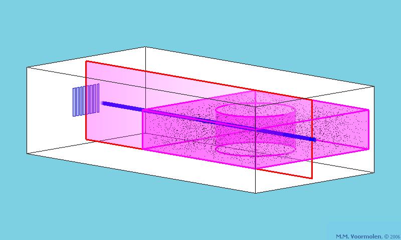
21 Plane disk transducer
")
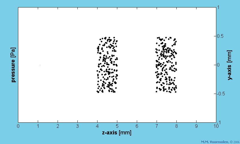
22 Intensity (space)
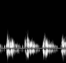
23 Frequency Spectrum a) Time domain b) Frequency domain (FFT)
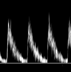
24 Nonlinear propagation At high ultrasound pressure Time domain asymmetrical pattern Frequency domain (FFT) Harmonic frequencies
25 Bibliography McDicken W.N. Diagnostic Ultrasonics Churchill Livingstone New York Barnett E., Morley P. Clinical Diagnostic Ultrasound Blackwell Scientific Publications, Oxford Meire H.B., Cosgrove D.O., Dewbury K.C., Farrant P. Clinical Ultrasound a comprehensive text: Abdominal and General Ultrasound Vol.2 Churchill Livingstone New York 2001.
26 The Engineering of Ultrasound Imaging Vassilis Sboros Medical Physics and Cardiovascular Sciences University of Edinburgh
27 Transducer Engineering - Piezoelectric materials Positive Voltage = compression Synthetic ceramic - Lead Zirconate Titanate(PZT) High sensitivity High acoustic power Easy to micromachine Impedance 20x tissue Thickness = λ/2 -resonance Resonance due to internal reflection Determines transmit frequency
28 Transducer Engineering Backing layer PZT Impedance 20x tissue Duration of pulse difficult to control due to internal ringing Backing layer = absorber High impedance Reduces ringing
29 Transducer Engineering Matching layer PZT Impedance 20x tissue Only 20% of energy transmitted to tissue Matching layer = impedance matching Impedance lower than PZT and higher than tissue Remove some ringing 1 layer 2x sensitivity λ/4 thickness Constructive interference towards tissue Destructive interference towards PZT
30 Transducer Engineering Frequency bandwidth vssensitivity High sensitivity = specific dimensions for Backing, PZT and Matching layers Frequency band is narrow Resolution low >1 Matching layers Decreasing impedance Bandwidth 2x (60% to 120%) Little loss in sensitivity

31 1D Single Plane disk transducer
 Trapezoidal d) Sector e)")
32 2D beams Array transducers a) Linear b) Curvilinear c) Trapezoidal d) Sector e) Radial
33 Transducer Engineering Lens Single element Focus has high sensitivity and resolution Linear Array Electronically in scan plane Only in elevation plane Phased Array Mild in scan plane Stronger in elevation plane

34 Linear Array Transducers 128 elements Binary processing Choice of frequency Penetration vsresolution or attenuation vs frequency Dimensions ~ 1/f ~1.3λwidth per element ~30λ height - elevation
 Receive (<20 to >20 as depth increases) Electronic")
35 Linear Array Transducers Active group of elements Finite beam per element Transmit fixed (~20) Receive (<20 to >20 as depth increases) Electronic focus
36 Linear Array Transducers Transmit Electronic Focus Transmission timing One focus Controllable
37 Linear Array Transducers Receive Electronic Focus Electronic delay Depth ~ element number Multiple foci Not controllable/automatic High resolution at all depths

38 Linear Array Transducers Transmit Multiple focus

39 Linear Array Transducers 1.5D array for improved elevation focus

40 Linear Array Transducers Transmit Apodization
41 Curvilinear Array Transducers Sector scanning Wider field Linear array structure Active element number reduced - Poorer resolution
 Shorter near field per element Wider far field per element Beam steering ±45")
42 Phased Array Transducers Sector scanning Narrow acoustic window Narrower elements All elements used (transmit and receive) Shorter near field per element Wider far field per element Beam steering ±45 o

43 Linear/Phased Array Transducers Compounding Reduction of noise Persistence Reduction of frame rate
44 Matrix Array Transducers
45 EndocavityArray Transducers a) Curvilinear transvaginal b) Curvilinear Transvaginal, transrectal c) Bi-plane Transrectal (prostate) d) Phased array Transoesophageal(heart)
46 Intravascular Array Transducers Curvilinear/convex 360 o High frequency (30MHz) Vessel wall
47 phantom
48 A-mode (transmission)
49 A-mode
50 Eye A-mode

51 B-mode scanning

52 Eye B-mode
53 B-mode Formation of B-mode image
54 B-mode
55 B-mode Transmit gain and power
 Compensate for")
56 B-mode Time gain compensation (TGC) Compensate for attenuation
 digital")
57 B-mode Analogue to digital conversion limited values memory binary system sampling rate (40MHz) digital processing
58 B-mode Digital signal Rectification Enveloping
59 B-mode Compression Accommodate in the image low and high echoes

60 B-mode Image memory
61 B-mode Interpolation Linear?

62 B-mode Reading of image memory to form display Gray scale

63 Ultrasound Imaging Modes Real-time 2D imaging Good spatial resolution Good temporal resolution Good Penetration Heart scan


64 Ultrasound Imaging Modes 3D and 4D Good spatial resolution Poor temporal resolution OK Penetration Foetal scan Heart scan
65 Doppler Ultrasound Pete Hoskins and Vassilis Sboros Medical Physics and Cardiovascular Sciences University of Edinburgh
66 Doppler ultrasound Principles of Doppler CW/PW Doppler Doppler systems (spectral, duple, colour) and controls Principles of contrast imaging

67 Doppler effect
68 Controls Doppler system patient
69 Doppler effect Change in pitch is proportional to speed of source Change in pitch = f S -f O Doppler shift = f d = f S -f O Speed = v f d ~v
70 Doppler ultrasound Transducer Blood Transmission T Scattering R Reception R
71 Case 1. Blood stationary Transmission T Scattering R Reception R f r = f t
72 Case 2. Blood moving away from transducer Transmission T Scattering R Reception R f r < f t
73 Case 3. Blood moving towards transducer Transmission T Scattering R Reception R f r > f t
74 General case f t v f r = f t + f d f d = 2 f t v/c
75 Some values Transmit frequency Speed of sound Speed of blood 4 MHz 1540 m/s 1 m/s Doppler shift = 5194 Hz Hear Doppler signal
76 Doppler ultrasound Transmission Scattering Reception f t f r
77 Doppler ultrasound f t + f d f t θ v f d = 2 f t v cos θ/c
78 Cosine function Cosine Angle (degrees)

79 40 80 ο ο 60 ο
80 Some more values Transmit frequency Velocity Angle Speed of sound 3-5 MHz 0-3 m/s degrees 1540 m/s Doppler frequency shift 0-15 khz Audio range 0-20 khz Can hear Doppler shift frequencies
81 Doppler systems Spectral display Colour flow
 baseline Time")
82 Spectral display Frequency shift (khz) baseline Time (s)

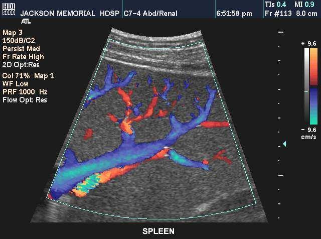
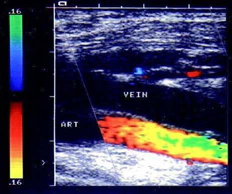
83 Colour flow
84 Triplex display
85 Summary of systems and main controls 2 main types of system are Spectral Doppler Colour flow main controls for spectral Doppler adjust: position of sensitive region beam direction spectral Doppler display main controls for colour flow adjust: size and depth of colour box beam direction colour display
86 Spectral Doppler Frequency shift (khz) baseline Time (s)
87 Spectral Doppler -continuous wave (CW) Doppler signal processor Display T R Transducer Sensitive region Separate transmit and receive elements Emits ultrasound continuously Receives ultrasound continuously Doppler signals from sensitive region
88 Stand alone CW Doppler system: features No B-mode image No depth discrimination Use for vessels at defined location Use for vessels with characteristic waveform shapes Obstetric applications - umbilical arteries Peripheral vascular application - carotid, lower limb


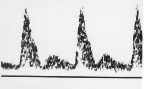
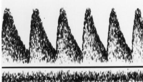
89 CW spectral Doppler examples Arcuateartery External iliac Internal iliac Umbilical

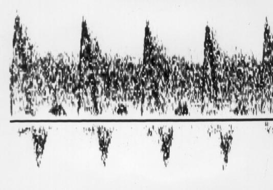
90 2 vessels in beam
91 Pulsed wave (PW) Doppler systems Doppler signal processor Display Sensitive region Gate depth Emits ultrasound in pulses Gate length Depth discrimination Sensitive region depth and length set by user
92 Stand alone PW Doppler system -features No B-mode image Depth discrimination Use for vessels at defined location Use for vessels with characteristic waveform shapes Transcranial
93 Duplex system B-mode + PW Doppler = Duplex
94 Duplex system -features B-mode and PW Doppler depth discrimination all cardiovascular applications basis for all modern Doppler systems
95 System components and signal processing Doppler signal processor Display T R Tissue Blood Tissue Blood
96 Amplitude Received signal T R Blood Tissue From tissue (Clutter) From blood Tissue Frequency (MHz) Blood
97 Amplitude Demodulation Frequency (MHz) Frequency (Hz) Demodulation removes underlying transmit frequency
98 High pass filter Lost blood signal Frequency (Hz) Filter frequency thresholds Filtering removes the clutter signal
99 Amplitude 10ms Time Spectrum analysis Doppler frequency Time Spectrum analysis estimates all the frequencies present in the Doppler signal
100 Transducer Signal processor Received signal Frequency (MHz) Demodulator High pass filter Spectrum analysis Doppler signal Display Spectral display


101 Cut-off filter Filter low Filter high End diastolic flow Loss of end diastolic flow
102 Typical filter values Obstetrics Hz (little arterial movement) Vascular Hz (some arterial pulsation) cardiology 300Hz+ (valves and myocardium)
103 Pulsed wave (PW) Doppler Doppler signal processor Display Sensitive region Gate depth Gate length
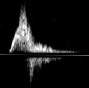
104 Doppler signal CW PW

105 Aliasing Upper limit to detected velocity measured using PW Doppler Max Doppler frequency shift
106 CW Doppler signal PW Doppler signal (lots of samples) PW Doppler signal (2 samples/wavelength) PW Doppler signal (not enough samples) Aliasing
107 Aliasing Doppler frequency shift estimated correctly when: at least 2 samples per wavelength prf> 2 f d Maximum Doppler frequency shift which can be estimated is half the prf f d(max) = prf/2
108 Waveforms in disease Local disease (Atherosclerosis) Downstream disease (placental disease)
109 Atherosclerosis Jet Turbulence
110 Max velocity Quantification 1. Peak velocity
111 Measurement of blood velocity I. Transducer θ v v = c f d 2f t cos θ

112 Measurement of blood velocity II.
113 Measurement of blood velocity III.
114 Standard table Diameter Peak systolic stenosis (%) velocity (cm/s) 0 < < < > > 230
115 Downstream disease Uterine artery Fetus Placenta Spiral/arcuate arteries Abnormal placental development leads to increase in resistance to flow

116 Umbilical waveforms
117 Quantification 2. Waveform shape. Max Mean Min Resistance index (RI) = (max-min)/max Pulsatility index (PI) = (max-min)/mean
118 Estimation of RI Peak systolic marker End diastolic marker
119 Controls for CW, PW and duplex position of sensitive region (PW, duplex) gate length, gate depth beam direction (PW, duplex) Beam steering angle spectral Doppler display (CW, PW, duplex) gain Filter level Velocity scale Time scale Baseline Measurement (duplex) Beam-vessel angle
120 Colour flow
121
122
123 Colour flow image Display of 2D flow image superimposed on B-mode image
124 Colour boxes Sector Linear array Colour box Colour box Image built up line by line Each line consists of adjacent sample volumes
125 Colour flow system components Display B-scan processor Colour flow processor Spectral Doppler processor Beamformer Transducer Transmitters
126 Colour flow processor Demodulator Clutter filter Doppler statistic estimator Post processor Blood tissue discriminator
127 Clutter filter clutter blood Frequency (MHz) Frequency (MHz)
128 Frequency estimation Fast Fourier Transform ( data points) full frequency spectrum Autocorrelator(3 data points) mean frequency variance power
129 Post-processor Persistence or Frame-averaging Reduces noise lag in image High persistence Low persistence Value = 0.4 frame frame frame frame frame 5 Value = 0.6 frame frame 2
130 Colour image (mean Doppler frequency) Blood-tissue discriminator B-mode image

")

131 Colour image (mean Doppler frequency) Blood-tissue discriminator B-mode image

132 No blood tissue discriminator

133 With blood tissue discriminator
134 Colour modes Variance Colour processor Mean frequency Power Colour Doppler Power Doppler

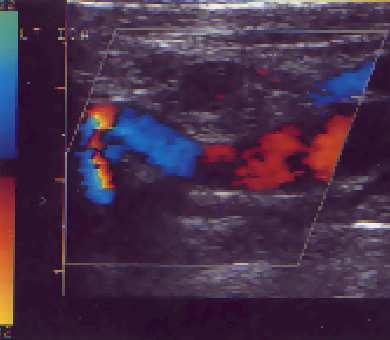
135 Mean frequency: red-blue scale

136 Mean frequency + variance: red-blue + green

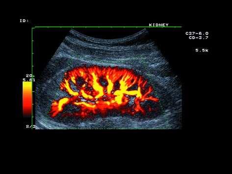
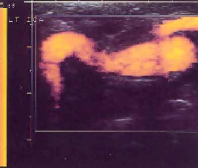
137 Power: no B-mode in colour box

138 Power: with B-mode in colour box
139 Angle dependence θ θ θ

140 Colour Doppler angle dependence

141 Power Doppler angle dependence
142 Angle dependence Doppler amplitude 40 o 90 o 60 o Doppler frequency Clutter filter
143 Angle dependence
144 Aliasing
145 Aliasing Doppler amplitude 3m/s 4m/s 1m/s 2m/s 3m/s Aliasing limit Doppler frequency Aliasing limit

146 Jet Recirculation
Lesson 02: Sound Wave Production. This lesson contains 24 slides plus 11 multiple-choice questions.
 Lesson 02: Sound Wave Production This lesson contains 24 slides plus 11 multiple-choice questions. Accompanying text for the slides in this lesson can be found on pages 2 through 7 in the textbook: ULTRASOUND
Lesson 12: Doppler Principles. This lesson contains 50 slides plus 26 multiple-choice questions.
 Lesson 12: Doppler Principles This lesson contains 50 slides plus 26 multiple-choice questions. Accompanying text for the slides in this lesson can be found on pages 59 through 80 in the textbook: DOPPLER
Doppler Ultrasound. Amanda Watson.
 Doppler Ultrasound Amanda Watson amanda.watson1@nhs.net Before we start Why does blood appear black on a B-mode image? B-mode echoes vs. Doppler echoes In B-Mode we are concerned with the position and
The physics of ultrasound. Dr Graeme Taylor Guy s & St Thomas NHS Trust
 The physics of ultrasound Dr Graeme Taylor Guy s & St Thomas NHS Trust Physics & Instrumentation Modern ultrasound equipment is continually evolving This talk will cover the basics What will be covered?
12/26/2017. Alberto Ardon M.D.
 Alberto Ardon M.D. 1 Preparatory Work Ultrasound Physics http://www.nysora.com/mobile/regionalanesthesia/foundations-of-us-guided-nerve-blockstechniques/index.1.html Basic Ultrasound Handling https://www.youtube.com/watch?v=q2otukhrruc
Physics of Ultrasound Ultrasound Imaging and Artifacts รศ.นพ.เดโช จ กราพาน ชก ล สาขาหท ยว ทยา, ภาคว ชาอาย รศาสตร คณะแพทยศาสตร ศ ร ราชพยาบาล
 Physics of Ultrasound Ultrasound Imaging and Artifacts รศ.นพ.เดโช จ กราพาน ชก ล สาขาหท ยว ทยา, ภาคว ชาอาย รศาสตร คณะแพทยศาสตร ศ ร ราชพยาบาล Diagnosis TTE TEE ICE 3D 4D Evaluation of Cardiac Anatomy Hemodynamic
The Physics of Echo. The Physics of Echo. The Physics of Echo Is there pericardial calcification? 9/30/13
 Basic Ultrasound Physics Kirk Spencer MD Speaker has no disclosures to make Sound Audible range 20Khz Medical ultrasound Megahertz range Advantages of imaging with ultrasound Directed as a beam Tomographic
SONOGRAPHIC PHYSICS, INSTRUMENTATION & DOPPLER REVIEW Part 3
 SONOGRAPHIC PHYSICS, INSTRUMENTATION & DOPPLER REVIEW 2012 Part 3 1 Doppler Imaging 2 DOPPLER TRANSDUCER SAME FREQUENCY During Doppler operation, the reflected sound has the same frequency as the transmitted
Doppler in Obstetrics: book by K Nicolaides, G Rizzo, K Hecher. Chapter on Doppler ultrasound: principles and practice by Colin Deane
 Doppler in Obstetrics: book by K Nicolaides, G Rizzo, K Hecher Chapter on Doppler ultrasound: principles and practice by Colin Deane INTRODUCTION Competent use of Doppler ultrasound techniques requires
Ultrasound Beamforming and Image Formation. Jeremy J. Dahl
 Ultrasound Beamforming and Image Formation Jeremy J. Dahl Overview Ultrasound Concepts Beamforming Image Formation Absorption and TGC Advanced Beamforming Techniques Synthetic Receive Aperture Parallel
Lesson 06: Pulse-echo Imaging and Display Modes. This lesson contains 22 slides plus 15 multiple-choice questions.
 Lesson 06: Pulse-echo Imaging and Display Modes This lesson contains 22 slides plus 15 multiple-choice questions. Accompanying text for the slides in this lesson can be found on pages 26 through 32 in
Ultrasound Physics. History: Ultrasound 2/13/2019. Ultrasound
 Ultrasound Physics History: Ultrasound Ultrasound 1942: Dr. Karl Theodore Dussik transmission ultrasound investigation of the brain 1949-51: Holmes and Howry subject submerged in water tank to achieve
Optimisation of Image Acquisition Bordeaux 16th November J.S. McGhie W.B. Vletter R. Frowijn No disclosures
 Optimisation of Image Acquisition Bordeaux 16th November 2016 J.S. McGhie W.B. Vletter R. Frowijn No disclosures Image optimisation: The Echo machine It looks difficult to drive an echo machine!! Some
Introduction to Medical Engineering (Medical Imaging) Ultrasound Imaging. Ho Kyung Kim Pusan National University
 Ultrasound Imaging. Ho Kyung Kim Pusan National University") Introduction to Medical Engineering (Medical Imaging) Suetens 6 Ultrasound Imaging Ho Kyung Kim Pusan National University Sound Sonic: 20 Hz 20 khz (audible frequency) Subsonic () Ultrasound
Introduction to Medical Engineering (Medical Imaging) Suetens 6 Ultrasound Imaging Ho Kyung Kim Pusan National University Sound Sonic: 20 Hz 20 khz (audible frequency) Subsonic () Ultrasound
Nuove tecnologie per ecografia ad ultrasuoni: da 2D a 4D
 DINFO Dipartimento di Ingegneria dell Informazione Department of Information Engineering Nuove tecnologie per ecografia ad ultrasuoni: da 2D a 4D Piero Tortoli Microelectronics Systems Design Lab 1 Introduction
Medical Imaging (EL582/BE620/GA4426)
") Medical Imaging (EL582/BE620/GA4426) Jonathan Mamou, PhD Riverside Research Lizzi Center for Biomedical Engineering New York, NY jmamou@riversideresearch.org On behalf of Prof. Daniel Turnbull Outline
Medical Imaging (EL582/BE620/GA4426) Jonathan Mamou, PhD Riverside Research Lizzi Center for Biomedical Engineering New York, NY jmamou@riversideresearch.org On behalf of Prof. Daniel Turnbull Outline
Ultrasound Imaging Ultr Michael Dadd 2007
 Ultrasound Imaging Ultrasound Physics & Instrumentation - Recommended Reading 1. Diagnostic Ultrasound: Principles and Instruments (7th Ed) Frederick W Kremkau W B Saunders Company 2. Applied Physics &
Lesson 06: Pulse-echo Imaging and Display Modes. These lessons contain 26 slides plus 15 multiple-choice questions.
 Lesson 06: Pulse-echo Imaging and Display Modes These lessons contain 26 slides plus 15 multiple-choice questions. These lesson were derived from pages 26 through 32 in the textbook: ULTRASOUND IMAGING
Physics of ultrasound
 1 Physics of ultrasound Basic principles Nature of ultrasound Sound = longitudinal, mechanical wave particles move parallel to direction of travel Audible sound < 20 khz Ultrasound > 20 khz Sound cannot
COMPUTER PHANTOMS FOR SIMULATING ULTRASOUND B-MODE AND CFM IMAGES
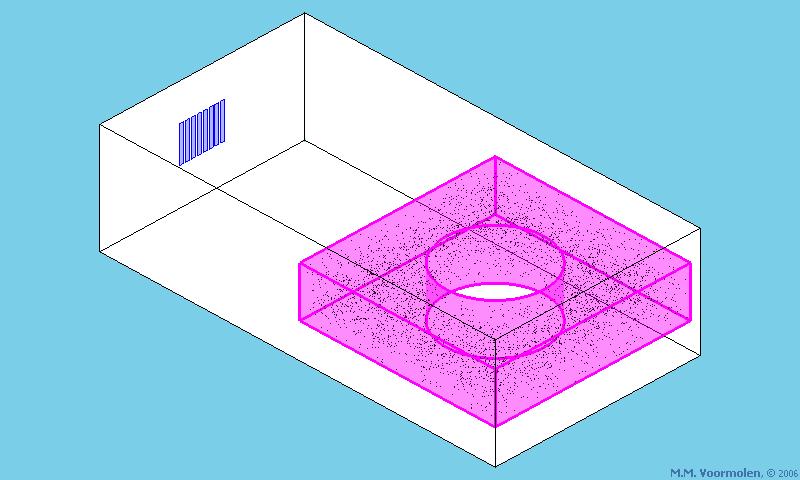
 Paper presented at the 23rd Acoustical Imaging Symposium, Boston, Massachusetts, USA, April 13-16, 1997: COMPUTER PHANTOMS FOR SIMULATING ULTRASOUND B-MODE AND CFM IMAGES Jørgen Arendt Jensen and Peter
Ultrasonic Linear Array Medical Imaging System
 Ultrasonic Linear Array Medical Imaging System R. K. Saha, S. Karmakar, S. Saha, M. Roy, S. Sarkar and S.K. Sen Microelectronics Division, Saha Institute of Nuclear Physics, 1/AF Bidhannagar, Kolkata-700064.
Sonic Distance Sensors
 Sonic Distance Sensors Introduction - Sound is transmitted through the propagation of pressure in the air. - The speed of sound in the air is normally 331m/sec at 0 o C. - Two of the important characteristics
Beamforming in ultrasound
 Peter Pazmany Catholic University Faculty of Information Technology www.itk.ppke.hu Medical diagnostic systems (Orvosbiológiai képalkotó rendszerek) Beamforming in ultrasound ( Nyalábalkotás az ultrahangban)
Ultrasound Bioinstrumentation. Topic 2 (lecture 3) Beamforming
 Beamforming") Ultrasound Bioinstrumentation Topic 2 (lecture 3) Beamforming Angular Spectrum 2D Fourier transform of aperture Angular spectrum Propagation of Angular Spectrum Propagation as a Linear Spatial Filter Free
Ultrasound Bioinstrumentation Topic 2 (lecture 3) Beamforming Angular Spectrum 2D Fourier transform of aperture Angular spectrum Propagation of Angular Spectrum Propagation as a Linear Spatial Filter Free
INTRODUCTION. Have applications for imaging, detection and navigation.
 ULTRASONICS INTRODUCTION The word ultrasonic combines the Latin roots ultra - beyond sonic - sound. Having frequencies above the audible range i.e. above 20000Hz Have applications for imaging, detection
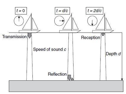
Chapter 4. Pulse Echo Imaging. where: d = distance v = velocity t = time
 Chapter 4 Pulse Echo Imaging Ultrasound imaging systems are based on the principle of pulse echo imaging. These systems require the use of short pulses of ultrasound to create two-dimensional, sectional
3. Ultrasound Imaging(2)
") 3. Ultrasound Imaging(2) Lecture 13, 14 Medical Imaging Systems Jae Gwan Kim, Ph.D. jaekim@gist.ac.kr, X 2220 Department of BioMedical Science and Engineering Gwangju Institute of Sciences and Technology
3. Ultrasound Imaging(2) Lecture 13, 14 Medical Imaging Systems Jae Gwan Kim, Ph.D. jaekim@gist.ac.kr, X 2220 Department of BioMedical Science and Engineering Gwangju Institute of Sciences and Technology
Image Optimization: The Sonographer s Responsibility. Prepared by Cathy Daniels, EdD, RTR, RDMS, RDCS, RVT
 Image Optimization: The Sonographer s Responsibility Prepared by Cathy Daniels, EdD, RTR, RDMS, RDCS, RVT Image Optimization: The Sonographer s Responsibility Cathy Daniels, EdD, RTR, RDMS, RDCS, RVT Disclosure
Explain what is meant by a photon and state one of its main properties [2]
![Explain what is meant by a photon and state one of its main properties [2]](/thumbs/80/82516318.jpg "Explain what is meant by a photon and state one of its main properties [2]") 1 (a) A patient has an X-ray scan taken in hospital. The high-energy X-ray photons interact with the atoms inside the body of the patient. Explain what is meant by a photon and state one of its main properties....
1 (a) A patient has an X-ray scan taken in hospital. The high-energy X-ray photons interact with the atoms inside the body of the patient. Explain what is meant by a photon and state one of its main properties....
Ultrasound & Artifacts
 ISSN 2005-7881 Journal of Neurosonology 3(Suppl. 2):1-17, 2011 Ultrasound & Artifacts Siryung Han The Catholic University of Korea Artifacts False image- echoes without anatomic correlate US image dose
Architecture of Quality Imaging Mary K. Henne, MS, CNMT, RDMS, RVT Ultrasound Education Specialist GE Healthcare
 Architecture of Quality Imaging Mary K. Henne, MS, CNMT, RDMS, RVT Ultrasound Education Specialist GE Healthcare 2 DOC1292532 Architecture of Quality Imaging Agile Acoustic Architecture E-Series and XDclear
BEAM DISTORTION IN DOPPLER ULTRASOUND FLOW TEST RIGS: MEASUREMENT USING A STRING PHANTOM
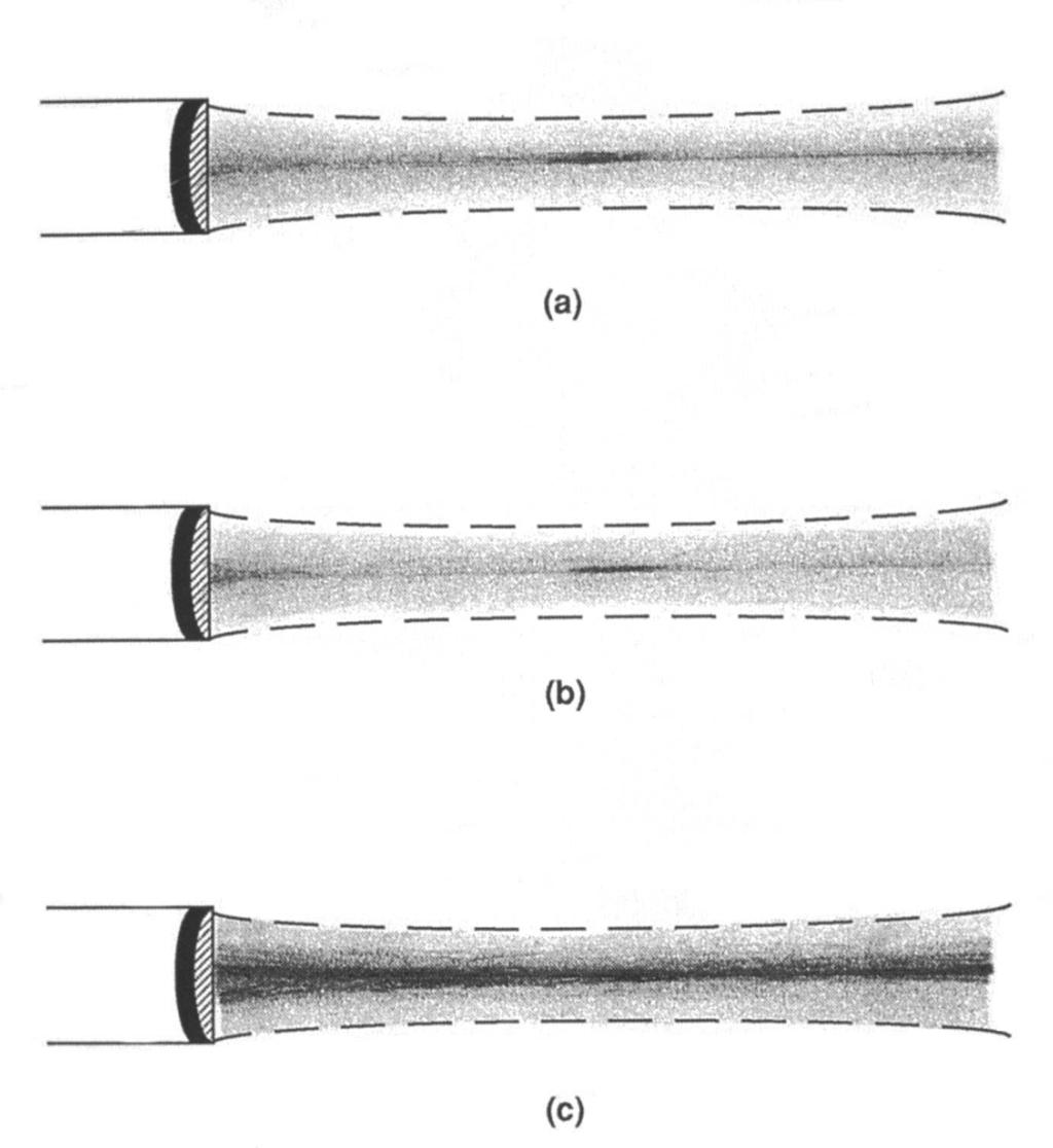
 BEAM DISTORTION IN DOPPLER ULTRASOUND FLOW TEST RIGS: MEASUREMENT USING A STRING PHANTOM R. Steel, P. J. Fish School of Informatics, University of Wales, Bangor, UK Abstract-The tube in flow rigs used
Lecture 19. Ultrasound Imaging
 Lecture 19 Ultrasound Imaging Contents 1. Introduction 2. Ultrasound and its generation 3. Wave propagation in the matter 4. Data acquisition (A, B, M and Doppler model) 5. Imaging reconstruction (5 steps)
Physics of Ultrasound & Doppler. Sang Jae Rhee. MD., PhD. Division of Cardiovascular Medicine Wonkwang University Hospital
 Physics of Ultrasound & Doppler Sang Jae Rhee. MD., PhD. Division of Cardiovascular Medicine Wonkwang University Hospital Classification of Sound Infrasound Audible sound Ultrasound < 20 Hz 20-20,000 Hz
Medical Imaging. X-rays, CT/CAT scans, Ultrasound, Magnetic Resonance Imaging
 Medical Imaging X-rays, CT/CAT scans, Ultrasound, Magnetic Resonance Imaging From: Physics for the IB Diploma Coursebook 6th Edition by Tsokos, Hoeben and Headlee And Higher Level Physics 2 nd Edition
Fig. 1
 PhysicsAndMathsTutor.com 1 1. Fig. 1 shows data for the intensity of a parallel beam of X-rays after penetration through varying thicknesses of a material. intensity / MW m 2 thickness / mm 0.91 0.40 0.69
Ultrasound physical principles in today s technology
 Education Ultrasound physical principles in today s technology Brian Starkoff M.App.Sc.(Med. Ultrasound), AMS Holland Park Brisbane Queensland Australia Correspondence to email starkoff@optusnet.com.au
M5 Diagnostic Ultrasound System
 V0807 M5 Diagnostic Ultrasound System Mindray s ultrasound family is now introducing a new member, M5 hand-carried color Doppler system. M5, coming in a laptop size with comprehensive ergonomic design,
DC-6. Diagnostic Ultrasound System
 DC-6 Diagnostic Ultrasound System DC-6 is a general purpose color Doppler ultrasound system aiming at most clinical areas both in exam and research with various transducers and multi software packages
4 Working With Scan Modes
 4 Working With Scan Modes Scan Modes Overview All of the information in this chapter pertains to live imaging. Many of the controls and functions change when you freeze the scan. For information on using
Principles of Ultrasound Imaging Image Optimization
 Principles of Ultrasound Imaging Image Optimization Robert A. Levine, MD, FACE, ECNU Thyroid Center of New Hampshire Geisel School of Medicine at Dartmouth College Disclosures: No relevant financial or
SODAR- sonic detecting and ranging
 Active Remote Sensing of the PBL Immersed vs. remote sensors Active vs. passive sensors RADAR- radio detection and ranging WSR-88D TDWR wind profiler SODAR- sonic detecting and ranging minisodar RASS RADAR
Doppler Ultrasound Blood Flow Measurement System for Assessing Coronary Revascularization
 Doppler Ultrasound Blood Flow Measurement System for Assessing Coronary Revascularization J. Solano 1, M. Fuentes 1, A. Villar 2 J. Prohias 2, F. García-Nocetti 1 1 Universidad Nacional Autónoma de México,
Ultrasound Physics and Instrumentation, 5e Chapter 7: Level 1 Quiz Answers. 1) Which of the following is stated in the introduction of the chapter?
 Which of the following is stated in the introduction of the chapter?") Ultrasound Physics and Instrumentation, 5e Chapter 7: Level 1 Quiz Answers 1) Which of the following is stated in the introduction of the chapter? a) Because of the importance of Doppler, this chapter
Ultrasound Physics and Instrumentation, 5e Chapter 7: Level 1 Quiz Answers 1) Which of the following is stated in the introduction of the chapter? a) Because of the importance of Doppler, this chapter
Photomultiplier Tube
 Nuclear Medicine Uses a device known as a Gamma Camera. Also known as a Scintillation or Anger Camera. Detects the release of gamma rays from Radionuclide. The radionuclide can be injected, inhaled or
Velocity Estimation in muscular Tissue by Ultrasound
 Velocity Estimation in muscular Tissue by Ultrasound Trond-Olav Dahl Master of Science in Communication Technology Submission date: June 2007 Supervisor: Tor Audun Ramstad, IET Co-supervisor: Hans Torp,
Artifacts. Artifacts. Causes. Imaging assumptions. Common terms used to describe US images. Common terms used to describe US images
 Artifacts Artifacts Chapter 20 What are they? Simply put they are an error in imaging These artifacts include reflections that are: not real incorrect shape, size or position incorrect brightness displayed
ACOUSTIC MICRO IMAGING ANALYSIS METHODS FOR 3D PACKAGES
 ACOUSTIC MICRO IMAGING ANALYSIS METHODS FOR 3D PACKAGES Janet E. Semmens Sonoscan, Inc. Elk Grove Village, IL, USA Jsemmens@sonoscan.com ABSTRACT Earlier studies concerning evaluation of stacked die packages
Key Physics and Doppler Principles
 Key Physics and Doppler Principles Robert A. Levine, MD, FACE, ECNU Thyroid Center of New Hampshire Geisel School of Medicine at Dartmouth College AACE/ACE Advanced Neck Ultrasound Training Course Disclosures:
Interaction of Sound and. logarithms. Logarithms continued. Decibels (db) Decibels (db) continued. Interaction of Sound and Media continued
 Decibels (db) continued. Interaction of Sound and Media continued") Interaction of Sound and Media continued Interaction of Sound and Media Chapter 6 As sound travels through a media and interacts with normal anatomical structures its intensity weakens through what is
Interaction of Sound and Media continued Interaction of Sound and Media Chapter 6 As sound travels through a media and interacts with normal anatomical structures its intensity weakens through what is
Incoherent Scatter Experiment Parameters
 Incoherent Scatter Experiment Parameters At a fundamental level, we must select Waveform type Inter-pulse period (IPP) or pulse repetition frequency (PRF) Our choices will be dictated by the desired measurement
Physics in Modern Medicine Fall 2010
 Physics in Modern Medicine Fall 2010 Homework #3 Chapter 3 Lasers in Medicine Questions Q3.1 Absorption in melanin increases with decreasing wavelength, and has a maximum, according to figure 3.23 in the
CHAPTER 1 INTRODUCTION
 CHAPTER 1 INTRODUCTION Spatial resolution in ultrasonic imaging is one of many parameters that impact image quality. Therefore, mechanisms to improve system spatial resolution could result in improved
(A) 2f (B) 2 f (C) f ( D) 2 (E) 2
 2f (B) 2 f (C) f ( D) 2 (E) 2") 1. A small vibrating object S moves across the surface of a ripple tank producing the wave fronts shown above. The wave fronts move with speed v. The object is traveling in what direction and with what
1. A small vibrating object S moves across the surface of a ripple tank producing the wave fronts shown above. The wave fronts move with speed v. The object is traveling in what direction and with what
Real Time Deconvolution of In-Vivo Ultrasound Images
 Paper presented at the IEEE International Ultrasonics Symposium, Prague, Czech Republic, 3: Real Time Deconvolution of In-Vivo Ultrasound Images Jørgen Arendt Jensen Center for Fast Ultrasound Imaging,
monitoring device ought to find wide clinical application. available, while section three describes the Doppler interface with the B-scan machine.
 THE YALE JOURNAL OF BIOLOGY AND MEDICINE 50 (1977), 367-373 Pulse-Doppler Ultrasound and Its Clinical Application PETER ATKINSON AND PETER N.T. WELLS Yale University School of Medicine, New Haven, Connecticut
Ultrasonic Level Detection Technology. ultra-wave
 Ultrasonic Level Detection Technology ultra-wave 1 Definitions Sound - The propagation of pressure waves through air or other media Medium - A material through which sound can travel Vacuum - The absence
Chapter 8. Ultrasound Medical Diagnostic Instrumentation PART-I
 Chapter 8 Ultrasound Medical Diagnostic Instrumentation PART-I ULTRASONAGRAPHY Ultrasonography is a technique by which ultrasonic energy is used to detect internal body organs. Bursts of ultrasound energy
INTRODUCTION TO RADAR SIGNAL PROCESSING
 INTRODUCTION TO RADAR SIGNAL PROCESSING Christos Ilioudis University of Strathclyde c.ilioudis@strath.ac.uk Overview History of Radar Basic Principles Principles of Measurements Coherent and Doppler Processing
Lecture 9. Radar Equation. Dr. Aamer Iqbal. Radar Signal Processing Dr. Aamer Iqbal Bhatti
 Lecture 9 Radar Equation Dr. Aamer Iqbal 1 ystem Losses: Losses within the radar system itself are from many sources. everal are described below. L PL =the plumbing loss. L PO =the polarization loss. L
Waves & Interference
 Waves & Interference I. Definitions and Types II. Parameters and Equations III. Sound IV. Graphs of Waves V. Interference - superposition - standing waves The student will be able to: HW: 1 Define, apply,
Proceedings of Meetings on Acoustics
 Proceedings of Meetings on Acoustics Volume 19, 2013 http://acousticalsociety.org/ ICA 2013 Montreal Montreal, Canada 2-7 June 2013 Physical Acoustics Session 2pPA: Material Characterization 2pPA9. Experimental
Quick Reference Guide
 siemens.com/nx3 Quick Reference Guide ACUSON NX3 Series Contents 2 System Overview 3 Getting Started 8 2D Mode and M-mode 12 Color and Spectral Doppler 24 Measurements and Calculations 38 Text, Arrows
Spectral Distance Amplitude Control for Ultrasonic Inspection of Composite Components
 ECNDT 26 - Mo.2.6.4 Spectral Distance Amplitude Control for Ultrasonic Inspection of Composite Components Uwe PFEIFFER, Wolfgang HILLGER, DLR German Aerospace Center, Braunschweig, Germany Abstract. Ultrasonic
SONOACE 6000C MT DIGITAL COLOR. Affordable PC-based Digital CFM Ultrasound System. Specifications.
 Specifications Imaging Modes Gray Scale Focusing PC Monitor Speaker Measurements Image Processing Display Functions Peripheral Devices Support Physical Dimensions Electrical Parameters Probe Types Single
Answer: TGC is needed to amplify echoes from deeper structures so that they appear as bright as similar structures located at more shallow depths.
 Q47. When performing a sonogram why the sonographer needs to use the TGC? TGC is needed to amplify echoes from deeper structures so that they appear as bright as similar structures located at more shallow
S S S2 Operation Manual
 PREPARATION 1. How to create and input patient data? In the MAIN INTERFACE, press the key, to enter into the patient exam list interface. Then, click New patient item to create new patient files. Patient
A Study on analysis of intracranial acoustic wave propagation by the finite difference time domain method
 A Stud on analsis of intracranial acoustic wave propagation b the finite difference time domain method 4.5 Wa Biological effects of ultrasound, ultrasonic tomograph Yoko Tanikaga, Toshikazu Takizawa, Takefumi
AN ULTRASOUND MODELING TOOL FOR CONTRAST AGENT IMAGING. Kangqiao Zhao, 2010, May
 AN ULTRASOUND MODELING TOOL FOR CONTRAST AGENT IMAGING -- Introduction ti to BubbleSim Kangqiao Zhao, 2010, May OUTLINE Introduction to Contrast Agent Imaging Applications Detection ti techniques Mechanical
Biomedical. Measurement and Design ELEC4623/ELEC9734. Electrical Safety and Performance Standards
 Biomedical Instrumentation, Measurement and Design ELEC4623/ELEC9734 Electrical Safety and Performance Standards Contents Physiological Effects of Electrical Currents Safety Standards for Medical Instrumentation
Ch 26: Sound Review 2 Short Answers 1. What is the source of all sound?
 Ch 26: Sound Review 2 Short Answers 1. What is the source of all sound? 2. How does a sound wave travel through air? 3. What media transmit sound? 4. What determines the speed of sound in a medium? 5.
Set No.1. Code No: R
 Set No.1 IV B.Tech. I Semester Regular Examinations, November -2008 RADAR SYSTEMS ( Common to Electronics & Communication Engineering and Electronics & Telematics) Time: 3 hours Max Marks: 80 Answer any
R. J. Jones College of Optical Sciences OPTI 511L Fall 2017
 R. J. Jones College of Optical Sciences OPTI 511L Fall 2017 Active Modelocking of a Helium-Neon Laser The generation of short optical pulses is important for a wide variety of applications, from time-resolved
Acoustic resolution. photoacoustic Doppler velocimetry. in blood-mimicking fluids. Supplementary Information
 Acoustic resolution photoacoustic Doppler velocimetry in blood-mimicking fluids Joanna Brunker 1, *, Paul Beard 1 Supplementary Information 1 Department of Medical Physics and Biomedical Engineering, University
Intext Exercise 1 Question 1: How does the sound produced by a vibrating object in a medium reach your ear?
 Intext Exercise 1 How does the sound produced by a vibrating object in a medium reach your ear? When an vibrating object vibrates, it forces the neighbouring particles of the medium to vibrate. These vibrating
P6 Quick Revision Questions
 P6 Quick Revision Questions H = Higher tier only SS = Separate science only Question 1... of 50 Define wavelength Answer 1... of 50 The distance from a point on one wave to the equivalent point on the
Pass Ultrasound Physics Exam
 Pass Ultrasound Physics Exam Match the Answers By Mansoor Khan MBBS, RDMS, RDCS 1 Copyright 2014 Blue Cube Venture, LLC All rights reserved. The Pass Ultrasound Physics Exam Match the Answers is protected
2. Pulsed Acoustic Microscopy and Picosecond Ultrasonics
 1st International Symposium on Laser Ultrasonics: Science, Technology and Applications July 16-18 2008, Montreal, Canada Picosecond Ultrasonic Microscopy of Semiconductor Nanostructures Thomas J GRIMSLEY
Physics B Waves and Sound Name: AP Review. Show your work:
 Physics B Waves and Sound Name: AP Review Mechanical Wave A disturbance that propagates through a medium with little or no net displacement of the particles of the medium. Parts of a Wave Crest: high point
Fundamental Concepts of Radar
 Fundamental Concepts of Radar Dr Clive Alabaster & Dr Evan Hughes White Horse Radar Limited Contents Basic concepts of radar Detection Performance Target parameters measurable by a radar Primary/secondary
Dr. P. SREENIVASULU REDDY 2
 ENGINEERING PHYSICS UNIT II - ULTRASONICS SV COLLEGE OF ENGINEERING, KADAPA Syllabus: - Introduction - Production of ultrasonic's by piezoelectric method - Properties and detection Applications in non-destructive
CONTACT LASER ULTRASONIC EVALUATION OF CONSTRUCTION MATERIALS
 CONTACT LASER ULTRASONIC EVALUATION OF CONSTRUCTION MATERIALS Alexander A.KARABUTOV 1, Elena V.SAVATEEVA 2, Alexei N. ZHARINOV 1, Alexander A.KARABUTOV 1 Jr. 1 International Laser Center of M.V.Lomonosov
Chapter 7. Waves and Sound
 Chapter 7 Waves and Sound What is wave? A wave is a disturbance that propagates from one place to another. Or simply, it carries energy from place to place. The easiest type of wave to visualize is a transverse
Use of trig to find the vertical Or horizontal component of the initial velocity
 1(a)(i) Use of trig to find the vertical Or horizontal component of the initial velocity Use of suitable equations of motion to calculate total time of flight of the ball Use of v = s/t Total horizontal
4.6.1 Waves in air, fluids and solids Transverse and longitudinal waves Properties of waves
 4.6 Waves Wave behaviour is common in both natural and man-made systems. Waves carry energy from one place to another and can also carry information. Designing comfortable and safe structures such as bridges,
ACCURACY IMPROVEMENT ON NON-INVASIVE ULTRASONIC-DOPPLER FLOW MEASUREMENT BY UTILZING SHEAR WAVES IN METAL PIPE
 4th International Symposium on Ultrasonic Doppler Method for Fluid Mechanics and Fluid Engineering Sapporo, 6.-8. September, 24 ACCURACY IMPROVEMENT ON NON-INVASIVE ULTRASONIC-DOPPLER FLOW MEASUREMENT
Data and Computer Communications Chapter 3 Data Transmission
 Data and Computer Communications Chapter 3 Data Transmission Eighth Edition by William Stallings Transmission Terminology data transmission occurs between a transmitter & receiver via some medium guided
Optical coherence tomography
 Optical coherence tomography Peter E. Andersen Optics and Plasma Research Department Risø National Laboratory E-mail peter.andersen@risoe.dk Outline Part I: Introduction to optical coherence tomography
Session: 1E CONTRAST AGENTS II Chair: K. Ferrara University of California-Davis. 1E-1 10:30 a.m.
 Session: 1E CONTRAST AGENTS II Chair: K. Ferrara University of California-Davis 1E-1 10:30 a.m. PULSE INVERSION DOPPLER FOR BLOOD FLOW DETECTION IN THE MACRO- AND MICRO-VASCULATURE WITH ULTRASOUND CONTRAST
Determination of the correlation distance for spaced antennas on multipath HF links and implications for design of SIMO and MIMO systems.
 Determination of the correlation distance for spaced antennas on multipath HF links and implications for design of SIMO and MIMO systems. Hal J. Strangeways, School of Electronic and Electrical Engineering,
DC-6 Expert. Diagnostic Ultrasound System
 DC-6 Expert Diagnostic Ultrasound System MINDRAY has newly released DC-6 Expert, a general purpose color Doppler ultrasound system with full ergonomic designs, supplying more accessible exams, higher imaging
Ultrasound Transducers for Q+ Systems
 Analogic Ultrasound Product Specifications Ultrasound Transducers for Q+ Systems 00.050.231, Revision A, May 9, 2014 US Patents 6,216,029-6,325,759-6,558,326-6,911,008-7,274,325-8,088,070-8,556,815 - D654,178
Know how Pulsed Doppler radar works and how it s able to determine target velocity. Know how the Moving Target Indicator (MTI) determines target
 determines target") Moving Target Indicator 1 Objectives Know how Pulsed Doppler radar works and how it s able to determine target velocity. Know how the Moving Target Indicator (MTI) determines target velocity. Be able to
Moving Target Indicator 1 Objectives Know how Pulsed Doppler radar works and how it s able to determine target velocity. Know how the Moving Target Indicator (MTI) determines target velocity. Be able to
Ihor TROTS, Andrzej NOWICKI, Marcin LEWANDOWSKI
 ARCHIVES OF ACOUSTICS 33, 4, 573 580 (2008) LABORATORY SETUP FOR SYNTHETIC APERTURE ULTRASOUND IMAGING Ihor TROTS, Andrzej NOWICKI, Marcin LEWANDOWSKI Institute of Fundamental Technological Research Polish
NCERT solution for Sound
 NCERT solution for Sound 1 Question 1 How does the sound produce by a vibrating object in a medium reach your ear? When an object vibrates, it vibrates the neighboring particles of the medium. These vibrating
Design, Development and Characterization of. Wideband Polymer Ultrasonic Probes. for Medical Ultrasound Applications. A Thesis
 Design, Development and Characterization of Wideband Polymer Ultrasonic Probes for Medical Ultrasound Applications A Thesis Submitted to the Faculty of Drexel University by Vadivel Devaraju in partial
Diagnostic Ultrasound System. Operation Note
 M5 Diagnostic Ultrasound System Table of Contents System Introduction...3 Control Panel...4 Control Panel...5 Control Panel...6 Control Panel...7 Control Panel...8 Control Panel...9 Power ON / OFF the
Waves and Sound Practice Test 43 points total Free- response part: [27 points]
![Waves and Sound Practice Test 43 points total Free- response part: [27 points]](/thumbs/87/96934113.jpg "Waves and Sound Practice Test 43 points total Free- response part: [27 points]") Name Waves and Sound Practice Test 43 points total Free- response part: [27 points] 1. To demonstrate standing waves, one end of a string is attached to a tuning fork with frequency 120 Hz. The other end
Name Waves and Sound Practice Test 43 points total Free- response part: [27 points] 1. To demonstrate standing waves, one end of a string is attached to a tuning fork with frequency 120 Hz. The other end
Radar-Verfahren und -Signalverarbeitung
 Radar-Verfahren und -Signalverarbeitung - Lesson 2: RADAR FUNDAMENTALS I Hon.-Prof. Dr.-Ing. Joachim Ender Head of Fraunhoferinstitut für Hochfrequenzphysik and Radartechnik FHR Neuenahrer Str. 20, 53343