Ultrasound Bioinstrumentation. Topic 2 (lecture 3) Beamforming
|
|
|
- Juliana Hoover
- 5 years ago
- Views:
Transcription
")
1 Ultrasound Bioinstrumentation Topic 2 (lecture 3) Beamforming
2 Angular Spectrum 2D Fourier transform of aperture Angular spectrum
3 Propagation of Angular Spectrum
4 Propagation as a Linear Spatial Filter Free space propagation transfer function Input Angular Spectrum at z=0 Propagation Transfer Function Output Angular Spectrum at z
5 Fresnel Approximation Paraxial (near field) approximation
6 Fraunhofer Approximation Far field approximation Field = { Aperture }


7 Examples Rectangular aperture Circular aperture
8 Examples Array transducer Separable Solve two 1D problems
9 Field Calculation in Ultrasound Narrowband far-field analysis Totally unrealistic model Amazingly useful results will be used to introduce key points Wideband analysis Calculate at multiple wavelengths Weighted sum based on frequency spectrum of pulse Research field calculation software Field II (free) PiezoFlex (commercial)
10 Beamformer: Role in an Imager Perhaps the most important building block. Soul of the machine? Probably the most expensive building block % of parts & labor of a scanner
11 Beamformer History Before the mid-70s Single element scanners, no beamformer necessary Array based systems Analog beamformation Typically 32 channels Mid 1980s High channel count systems (High = 128) Early 90s Digital beamformation
12 Analog Beamformer

13 Hybrid Analog/Digital Beamformer

14 Digital Beamformer with Phase Shift

15 True Digital Beamformer
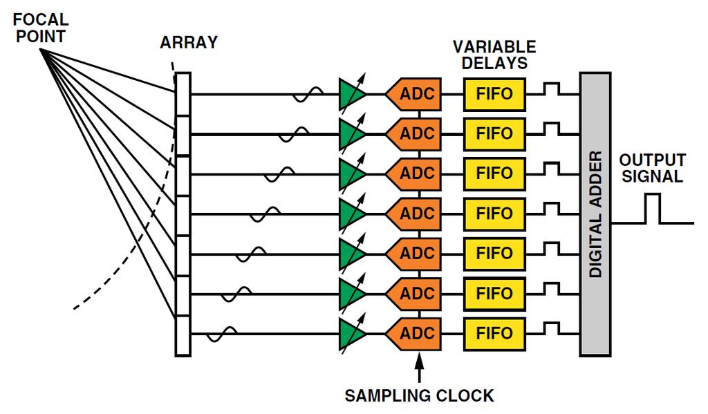
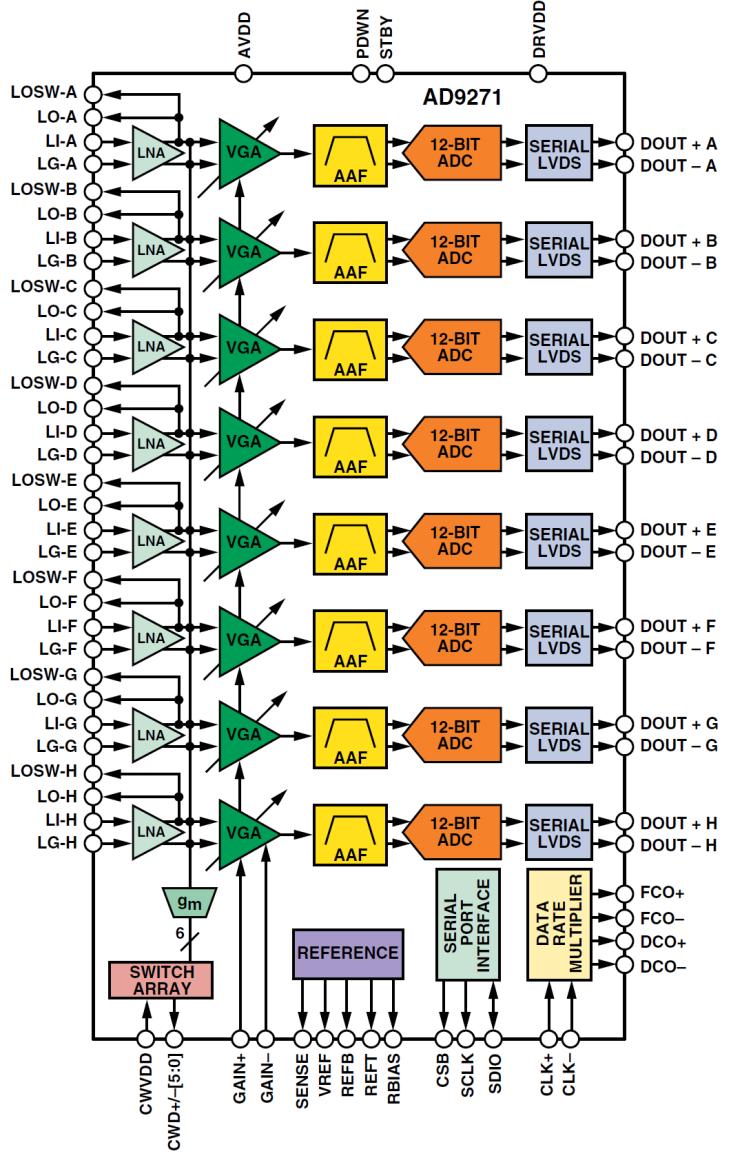
16 Digital Beamformer Hardware
17 Acoustic Wave Propagation Transmit voltages are typically in order of 100 V. These create pressures of appr. several 100 KPa. Typical tissue attenuation: 0.5 db/(cm MHz) Example: 10 cm 5 MHz 25 db one-way Backscatter from tissues -< 10% of incident pressure Transducer conversion efficiency 50 75% If we wish to display 40 db of info, we have to be able to handle > 100 db of dynamic range

18 Typical System Organization

19 Receive Beamformer Functions Delay generation, dynamic and steering delays Apodization Summing of all delayed signals
20 Focusing and Steering Delays

21 Transmit Vectors and Focal Zones

22 Apodization Main role apply a weighting function to aperture expand aperture w. receding wavefront maintain image uniformity supply walking aperture Implementation multipliers truly complex control Highly beneficial impact on beam.

23 Types of Arrays and Beamformers Linear array beamformer Generation of focusing delays Beam steering by element selection Curvilinear array beamformer Generation of focusing delays Beam steering by element selection Phased array beamformer Generation of focusing delays Beam steering by phasing


24 Array Geometries Definition of azimuth, elevation Scanning angle shown, θ, in negative scan direction. Similar definitions for a curved array

25 Delay Calculation from Geometry Delay determination: simple path length difference reference point: phase center apply Law of Cosines approximate for ASIC implementation In some cases, split delay into 2 parts: beam steering dynamic focusing
26 Transmit Beamforming
27 Resolution / Penetration Dilemma
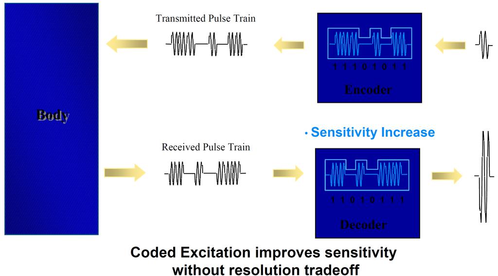
28 Coded Excitation

29 Coded Excitation: Example
30 Beam Compounding Compounding suppress speckle to improve contrast resolution Spatial compounding combine images from multiple angles Frequency compounding combine images from different frequencies
31 Targets of Ultrasound Imaging First level Gross anatomy basic measurements e.g. fetal dimensions often tissue/fluid interfaces not very challenging Second level soft tissue characteristics attenuation speckle size minimum acoustic noise beam performance critical Third level 3D/4D volume & surface rendering Beam performance critical

32 Quality Measures Image uniformity large depth of penetration reasonably uniform tissue texture Ability to bring out subtle changes. minimal beam distortion minimal reverberant noise

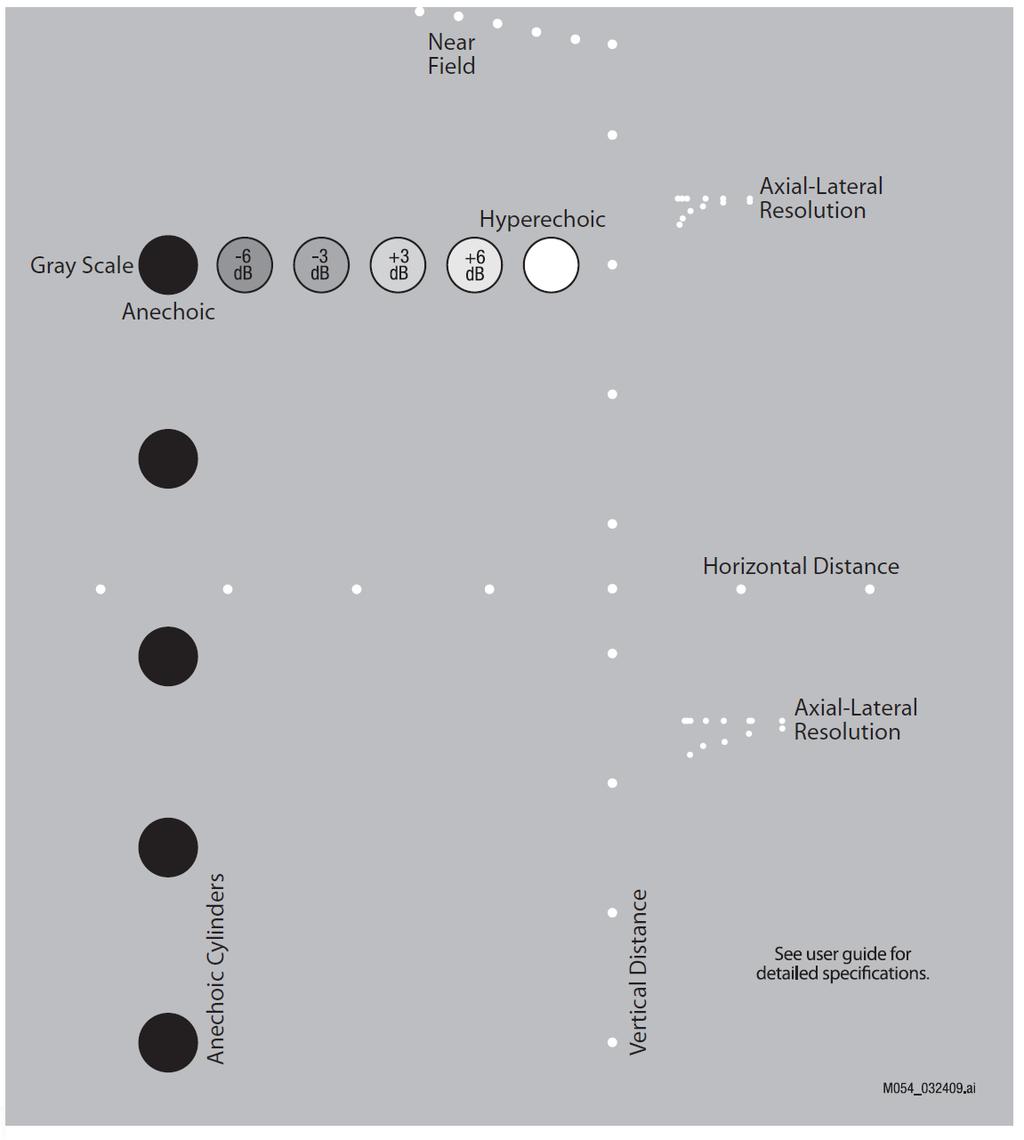
33 Quality Control Phantoms


34 Anatomy of an Ultrasound Beam Near field or Fresnel zone Far field or Fraunhofer zone Near-to-far field transition, L


35 Anatomy of an Ultrasound Beam Spatial resolution, beamwidth Depth of field (DOF) F-number

36 Beamformer Optimization Beam shape is improved by several processing steps: Transmit apodization Multiple transmit focal locations Dynamic focusing Dynamic receive apodization Post-beamsum processing Example Upper frame: fixed transmit focus Lower frame: the above steps.
37 Channel Count Issues First 128 channel system introduced in Huge majority of high-end systems are still at 128 channels. Does it make sense to go higher? What s the cost/benefit trade-off? Will the performance improve proportionately to the cost? What are some of the reasons for increasing it? Elevation focusing Real-time 3D/4D Aberration correction


38 Elevation Beamforming Limited performance available with 1D designs Poor beamformation away from elevation focus. Limits on size of elevation aperture due to fixed focus. Depth of focus inversely related to aperture size. Slice thickness improvement throughout image Expanding aperture, dynamic focusing in elevation
39 Array Taxonomy

40 Value of Elevation Focusing
41 Channel Count Requirements Let N = azimuthal channel count desired, e.g D no increase over N. 1.5D assume 5 rows (3 independent), 3N channels required 1.75D 2D with 5 rows, 5N channels required sparse arrays w. 256 channels currently available, for 4D For ergonomic scanning, no. of cables is <
42 3D/4D Imaging Physics Constraints Speed of sound in body = 1540 m/sec Image quality, Field of view, Volume update rate Can have any 2, not all 3 Example: 60 x 60 x 12 cm pyramid volume 1 beam spacing 3600 beams 12 cm x 2 / 1540 m/s = 160 μsec per beam 1.7 volumes / sec
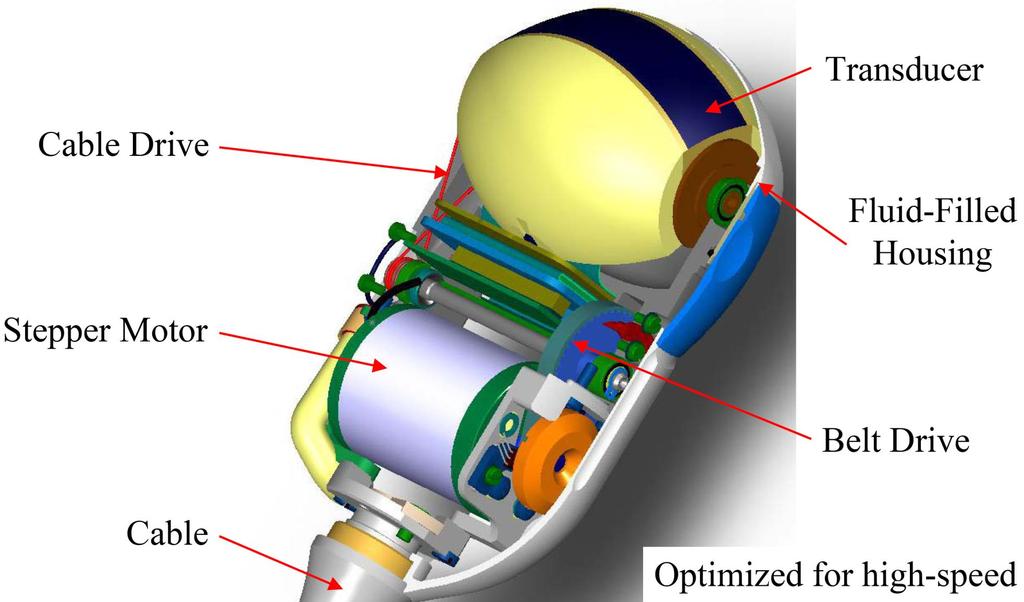
43 Mechanical 4D Probes
44 Concurrent Multi-Line Acquisition Transmit beam is broader than receive beam transmit is static focus, usually high f-number for max depth of field Create 2 16 simultaneous receive beams within the transmit beam Substantial increase in volume rate! Essential for effective 4D imaging
45 Harmonic Imaging Perhaps most important innovation of the last 10 yrs Now default mode in most cardiac scanners Discovery due to two major sources: harmonic imaging for contrast agents transducer bandwidth increases Arises from pressure dependence of sound speed Compressional wave is faster than rarefactional Need to understand via simulations.
46 Harmonic Imaging: Beamforming During propagation, harmonics are formed. Rate of generation of 2 nd harmonic proportional to p 2 This is equivalent to having an extra beamformer to narrow the beam shape. Beamformer requirements: added transmit flexibility increased filtering capacity Higher receive signal bandwidth
47 Harmonic Imaging: Advantages Harmonics formed at main lobe narrower beams lower sidelobes much acoustic noise generation at fundamental refraction from fat layers reverberations near fat/muscle layers Optimization of beamformers may be necessary

48 Harmonic Imaging Example 1

49 Harmonic Imaging Example 2

50 Harmonic Imaging with Contrast Ultrasound contrast agent Gas filled microbubbles Strong harmonic response Main clinical goal: perfusion Myocardial viability Presence of tumors Tissue harmonics confuse the issue Trend toward low frequency (1.5 MHz) operation
51 Comparison between Tissue and Contrast Harmonic Imaging Tissue Harmonics Goal: best tissue images Methods Maximize harmonic energy Higher f-numbers to allow harmonic energy to accumulate Consider non-spherical focusing Contrast Harmonics Goal: Show distribution of contrast agents Methods Minimize propagation harmonic energy Transmit harmonic energy that cancels propagation related harmonics. Alternative phasing scheme
52 Focusing Theory Fraunhofer diffraction pattern at focal depth when d=0
53 Focusing Implementation Reciprocity theorem Beamform at Transmit = beamform at Receive Overall beamform = Trans beamform x Rec beamform Static focusing Static focal point Used in transmission Dynamic focusing Multiple focal points Used in reception Ideally, focused in all points

54 Phase Aberration Present ultrasound imaging People are bags of water! Crude approximation Practical Imaging Fat and muscle degrade quality Time-delay Errors from the abdominal wall are Times Larger than beamformer delay quanta!
55 Phase Aberration All beamformers use an assumption of constant speed of sound (1540 m/s in all ultrasound systems) This assumption is not valid. In soft tissues, we have these speeds: fat 1440 m/s liver1510 kidney1560 muscle1570 (skeletal) Tumors1620 This variation limits further spatial & contrast resolution improvements.
56 Phase Aberration
57 Phase Aberration Solutions Phase screen models all aberrating sources near skin line deaberration can occur via time shifting of the echoes amount of shift determined by correlations. Distributed aberrators aberrating sources away from skin (as well as near it). Interference among refracted beams occurs. far more complex deaberration methods than time shifting is needed. Inverse filtering Assume a common source to all echoes Blind systems identification
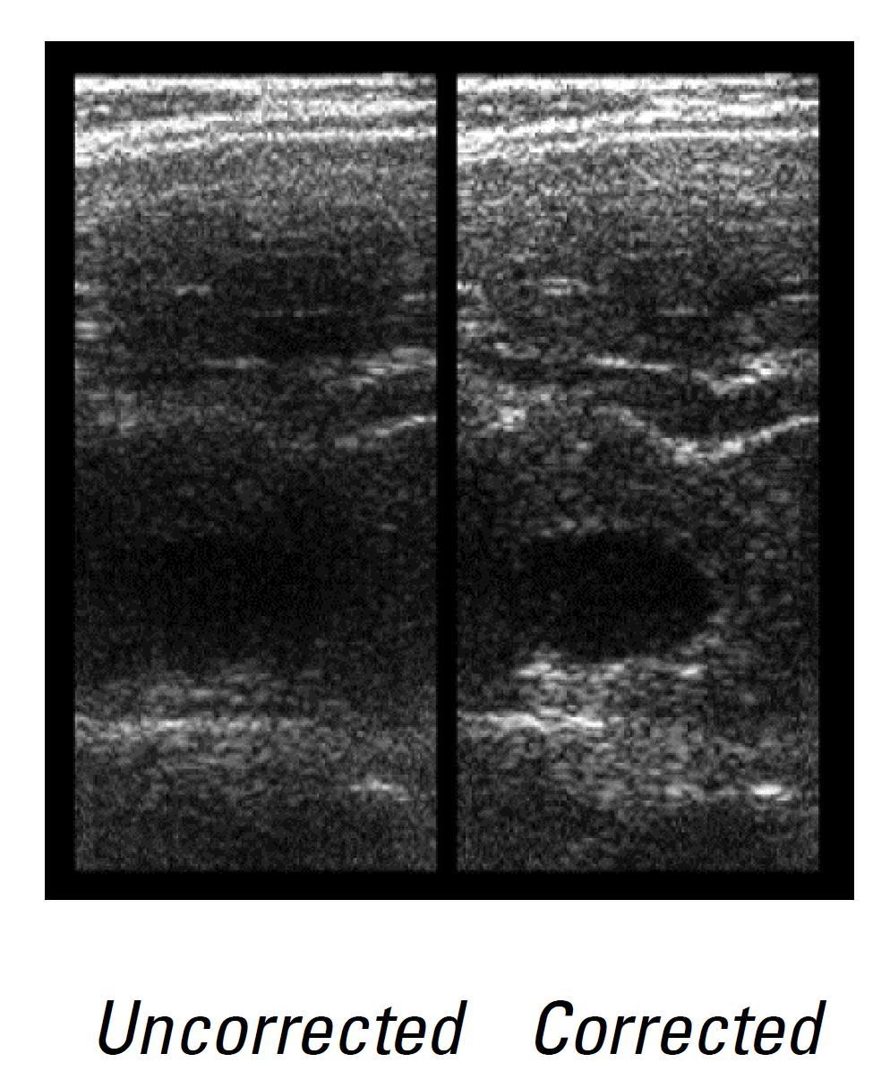
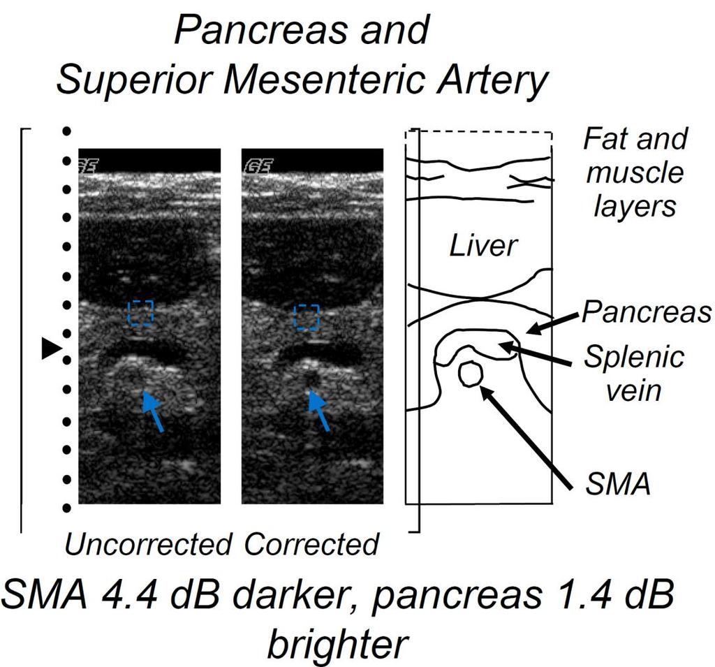
58 Phase Aberration Correction Results
59 Remaining Beamformer Issues Expanding aperture receive beamforming Synthetic aperture beamforming Digital beamforming Hilbert transformation Fractional period delay filters Sampling issues
60 Problem Assignments At the end of second lecture on Beamforming, there will be a problem assignment for you. Problems include programming tasks on Matlab or miniprojects.
Ultrasound Beamforming and Image Formation. Jeremy J. Dahl
 Ultrasound Beamforming and Image Formation Jeremy J. Dahl Overview Ultrasound Concepts Beamforming Image Formation Absorption and TGC Advanced Beamforming Techniques Synthetic Receive Aperture Parallel
COMPUTER PHANTOMS FOR SIMULATING ULTRASOUND B-MODE AND CFM IMAGES
 Paper presented at the 23rd Acoustical Imaging Symposium, Boston, Massachusetts, USA, April 13-16, 1997: COMPUTER PHANTOMS FOR SIMULATING ULTRASOUND B-MODE AND CFM IMAGES Jørgen Arendt Jensen and Peter
12/26/2017. Alberto Ardon M.D.
 Alberto Ardon M.D. 1 Preparatory Work Ultrasound Physics http://www.nysora.com/mobile/regionalanesthesia/foundations-of-us-guided-nerve-blockstechniques/index.1.html Basic Ultrasound Handling https://www.youtube.com/watch?v=q2otukhrruc
3. Ultrasound Imaging(2)
") 3. Ultrasound Imaging(2) Lecture 13, 14 Medical Imaging Systems Jae Gwan Kim, Ph.D. jaekim@gist.ac.kr, X 2220 Department of BioMedical Science and Engineering Gwangju Institute of Sciences and Technology
3. Ultrasound Imaging(2) Lecture 13, 14 Medical Imaging Systems Jae Gwan Kim, Ph.D. jaekim@gist.ac.kr, X 2220 Department of BioMedical Science and Engineering Gwangju Institute of Sciences and Technology
Ultrasound Physics. History: Ultrasound 2/13/2019. Ultrasound
 Ultrasound Physics History: Ultrasound Ultrasound 1942: Dr. Karl Theodore Dussik transmission ultrasound investigation of the brain 1949-51: Holmes and Howry subject submerged in water tank to achieve
Lesson 06: Pulse-echo Imaging and Display Modes. These lessons contain 26 slides plus 15 multiple-choice questions.
 Lesson 06: Pulse-echo Imaging and Display Modes These lessons contain 26 slides plus 15 multiple-choice questions. These lesson were derived from pages 26 through 32 in the textbook: ULTRASOUND IMAGING
Ultrasound Imaging Ultr Michael Dadd 2007
 Ultrasound Imaging Ultrasound Physics & Instrumentation - Recommended Reading 1. Diagnostic Ultrasound: Principles and Instruments (7th Ed) Frederick W Kremkau W B Saunders Company 2. Applied Physics &
Exercise 2: Simulation of ultrasound field using Field II
 Exercise 2: Simulation of ultrasound field using Field II The purposes of this exercise is to learn how to: Set up the simulation environment and model a transducer in Field II o Single element transducer
The physics of ultrasound. Dr Graeme Taylor Guy s & St Thomas NHS Trust
 The physics of ultrasound Dr Graeme Taylor Guy s & St Thomas NHS Trust Physics & Instrumentation Modern ultrasound equipment is continually evolving This talk will cover the basics What will be covered?
Physics of Ultrasound Ultrasound Imaging and Artifacts รศ.นพ.เดโช จ กราพาน ชก ล สาขาหท ยว ทยา, ภาคว ชาอาย รศาสตร คณะแพทยศาสตร ศ ร ราชพยาบาล
 Physics of Ultrasound Ultrasound Imaging and Artifacts รศ.นพ.เดโช จ กราพาน ชก ล สาขาหท ยว ทยา, ภาคว ชาอาย รศาสตร คณะแพทยศาสตร ศ ร ราชพยาบาล Diagnosis TTE TEE ICE 3D 4D Evaluation of Cardiac Anatomy Hemodynamic
Ultrasonic Linear Array Medical Imaging System
 Ultrasonic Linear Array Medical Imaging System R. K. Saha, S. Karmakar, S. Saha, M. Roy, S. Sarkar and S.K. Sen Microelectronics Division, Saha Institute of Nuclear Physics, 1/AF Bidhannagar, Kolkata-700064.
Artifacts. Artifacts. Causes. Imaging assumptions. Common terms used to describe US images. Common terms used to describe US images
 Artifacts Artifacts Chapter 20 What are they? Simply put they are an error in imaging These artifacts include reflections that are: not real incorrect shape, size or position incorrect brightness displayed
Multi-Element Synthetic Transmit Aperture Method in Medical Ultrasound Imaging Ihor Trots, Yuriy Tasinkevych, Andrzej Nowicki and Marcin Lewandowski
 Multi-Element Synthetic Transmit Aperture Method in Medical Ultrasound Imaging Ihor Trots, Yuriy Tasinkevych, Andrzej Nowicki and Marcin Lewandowski Abstract The paper presents the multi-element synthetic
Ihor TROTS, Andrzej NOWICKI, Marcin LEWANDOWSKI
 ARCHIVES OF ACOUSTICS 33, 4, 573 580 (2008) LABORATORY SETUP FOR SYNTHETIC APERTURE ULTRASOUND IMAGING Ihor TROTS, Andrzej NOWICKI, Marcin LEWANDOWSKI Institute of Fundamental Technological Research Polish
Architecture of Quality Imaging Mary K. Henne, MS, CNMT, RDMS, RVT Ultrasound Education Specialist GE Healthcare
 Architecture of Quality Imaging Mary K. Henne, MS, CNMT, RDMS, RVT Ultrasound Education Specialist GE Healthcare 2 DOC1292532 Architecture of Quality Imaging Agile Acoustic Architecture E-Series and XDclear
Beamforming in ultrasound
 Peter Pazmany Catholic University Faculty of Information Technology www.itk.ppke.hu Medical diagnostic systems (Orvosbiológiai képalkotó rendszerek) Beamforming in ultrasound ( Nyalábalkotás az ultrahangban)
CHAPTER 1 INTRODUCTION
 CHAPTER 1 INTRODUCTION Spatial resolution in ultrasonic imaging is one of many parameters that impact image quality. Therefore, mechanisms to improve system spatial resolution could result in improved
Medical Imaging (EL582/BE620/GA4426)
") Medical Imaging (EL582/BE620/GA4426) Jonathan Mamou, PhD Riverside Research Lizzi Center for Biomedical Engineering New York, NY jmamou@riversideresearch.org On behalf of Prof. Daniel Turnbull Outline
Medical Imaging (EL582/BE620/GA4426) Jonathan Mamou, PhD Riverside Research Lizzi Center for Biomedical Engineering New York, NY jmamou@riversideresearch.org On behalf of Prof. Daniel Turnbull Outline
Chapter 4. Pulse Echo Imaging. where: d = distance v = velocity t = time
 Chapter 4 Pulse Echo Imaging Ultrasound imaging systems are based on the principle of pulse echo imaging. These systems require the use of short pulses of ultrasound to create two-dimensional, sectional
Lesson 02: Sound Wave Production. This lesson contains 24 slides plus 11 multiple-choice questions.
 Lesson 02: Sound Wave Production This lesson contains 24 slides plus 11 multiple-choice questions. Accompanying text for the slides in this lesson can be found on pages 2 through 7 in the textbook: ULTRASOUND
INSTRUMENTATION DESIGN FOR ULTRASONIC IMAGING
 Source: STANDARD HANDBOOK OF BIOMEDICAL ENGINEERING AND DESIGN CHAPTER 25 INSTRUMENTATION DESIGN FOR ULTRASONIC IMAGING Kai E. Thomenius GE Corporate Research and Development, Schenectady, New York 25.1
Ultrasound physical principles in today s technology
 Education Ultrasound physical principles in today s technology Brian Starkoff M.App.Sc.(Med. Ultrasound), AMS Holland Park Brisbane Queensland Australia Correspondence to email starkoff@optusnet.com.au
Ultrasound & Artifacts
 ISSN 2005-7881 Journal of Neurosonology 3(Suppl. 2):1-17, 2011 Ultrasound & Artifacts Siryung Han The Catholic University of Korea Artifacts False image- echoes without anatomic correlate US image dose
Virtual ultrasound sources
 CHAPTER SEVEN Virtual ultrasound sources One of the drawbacks of the generic synthetic aperture, the synthetic transmit aperture, and recursive ultrasound imaging is the low signal-to-noise ratio (SNR)
Interaction of Sound and. logarithms. Logarithms continued. Decibels (db) Decibels (db) continued. Interaction of Sound and Media continued
 Decibels (db) continued. Interaction of Sound and Media continued") Interaction of Sound and Media continued Interaction of Sound and Media Chapter 6 As sound travels through a media and interacts with normal anatomical structures its intensity weakens through what is
Interaction of Sound and Media continued Interaction of Sound and Media Chapter 6 As sound travels through a media and interacts with normal anatomical structures its intensity weakens through what is
The Physics of Echo. The Physics of Echo. The Physics of Echo Is there pericardial calcification? 9/30/13
 Basic Ultrasound Physics Kirk Spencer MD Speaker has no disclosures to make Sound Audible range 20Khz Medical ultrasound Megahertz range Advantages of imaging with ultrasound Directed as a beam Tomographic
Linear arrays used in ultrasonic evaluation
 Annals of the University of Craiova, Mathematics and Computer Science Series Volume 38(1), 2011, Pages 54 61 ISSN: 1223-6934 Linear arrays used in ultrasonic evaluation Laura-Angelica Onose and Luminita
Reconfigurable Arrays for Portable Ultrasound
 Reconfigurable Arrays for Portable Ultrasound R. Fisher, K. Thomenius, R. Wodnicki, R. Thomas, S. Cogan, C. Hazard, W. Lee, D. Mills GE Global Research Niskayuna, NY-USA fisher@crd.ge.com B. Khuri-Yakub,
ULTRASONIC IMAGING of COPPER MATERIAL USING HARMONIC COMPONENTS
 ULTRASONIC IMAGING of COPPER MATERIAL USING HARMONIC COMPONENTS T. Stepinski P. Wu Uppsala University Signals and Systems P.O. Box 528, SE- 75 2 Uppsala Sweden ULTRASONIC IMAGING of COPPER MATERIAL USING
Harmonic Source Wavefront Correction for Ultrasound Imaging
 Harmonic Source Wavefront Correction for Ultrasound Imaging by Scott W. Dianis Department of Biomedical Engineering Duke University Date: Approved: Dr. Olaf T. von Ramm, Ph.D., Advisor Dr. Stephen W. Smith,
WHITE PAPER. Hybrid Beamforming for Massive MIMO Phased Array Systems
 WHITE PAPER Hybrid Beamforming for Massive MIMO Phased Array Systems Introduction This paper demonstrates how you can use MATLAB and Simulink features and toolboxes to: 1. Design and synthesize complex
APPLYING SYNTHETIC APERTURE, CODED EXCITATION, AND TISSUE HARMONIC IMAGING TECHNIQUES TO ALLOW ULTRASOUND IMAGING WITH A VIRTUAL SOURCE ROBYN T.
 APPLYING SYNTHETIC APERTURE, CODED EXCITATION, AND TISSUE HARMONIC IMAGING TECHNIQUES TO ALLOW ULTRASOUND IMAGING WITH A VIRTUAL SOURCE BY ROBYN T. UMEKI THESIS Submitted in partial fulfillment of the
Beamforming Techniques for Smart Antenna using Rectangular Array Structure
 International Journal of Electrical and Computer Engineering (IJECE) Vol. 4, No. 2, April 2014, pp. 257~264 ISSN: 2088-8708 257 Beamforming Techniques for Smart Antenna using Rectangular Array Structure
ADAPTIVE ANTENNAS. TYPES OF BEAMFORMING
 ADAPTIVE ANTENNAS TYPES OF BEAMFORMING 1 1- Outlines This chapter will introduce : Essential terminologies for beamforming; BF Demonstrating the function of the complex weights and how the phase and amplitude
Introduction to Ultrasound Physics
 Introduction to Ultrasound Physics Vassilis Sboros Medical Physics and Cardiovascular Sciences University of Edinburgh Transverse waves Water remains in position Disturbance traverse producing more wave
Principles of Ultrasound Imaging Image Optimization
 Principles of Ultrasound Imaging Image Optimization Robert A. Levine, MD, FACE, ECNU Thyroid Center of New Hampshire Geisel School of Medicine at Dartmouth College Disclosures: No relevant financial or
HIGH RESOLUTION MULTI-BEAM SIDE LOOKING SONAR ANDRZEJ ELMINOWICZ, LEONARD ZAJĄCZKOWSKI
 HIGH RESOLUTION MULTI-BEAM SIDE LOOKING SONAR ANDRZEJ ELMINOWICZ, LEONARD ZAJĄCZKOWSKI R&D Marine Technology Centre Dickmana 62, 81-109 Gdynia, POLAND email: andrzeje@ctm.gdynia.pl The conventional side
Retrospective Transmit Beamformation. Whitepaper. ACUSON SC2000 Volume Imaging Ultrasound System. Answers for life.
 Whitepaper Retrospective Transmit Beamformation ACUSON SC2000 Volume Imaging Ultrasound System Chuck Bradley, Ph.D. Siemens Healthcare Sector Ultrasound Business Unit Mountain View, California USA Answers
The Script of ZST + Presentation. MIS Upstream Marketing Team [ 日期 ]
![The Script of ZST + Presentation. MIS Upstream Marketing Team [ 日期 ]](/thumbs/94/119182132.jpg "The Script of ZST + Presentation. MIS Upstream Marketing Team [ 日期 ]") 1 The Script of ZST + Presentation MIS Upstream Marketing Team [ 日期 ] 1 The Script of ZST + Presentation Since Mindray was founded to develop ultrasound business, core technology has always been the engine
1 The Script of ZST + Presentation MIS Upstream Marketing Team [ 日期 ] 1 The Script of ZST + Presentation Since Mindray was founded to develop ultrasound business, core technology has always been the engine
UNIVERSITY OF OSLO. ultrasound imaging. Sverre Holm DEPARTMENT OF INFORMATICS
 High-resolution beamforming in ultrasound imaging Sverre Holm DEPARTMENT OF INFORMATICS MEDT8007 Simulation Methods in Ultrasound Imaging - NTNU Sverre Holm DEPARTMENT OF INFORMATICS Journal Publications
The Potential of Synthetic Aperture Sonar in seafloor imaging
 The Potential of Synthetic Aperture Sonar in seafloor imaging CM 2000/T:12 Ron McHugh Heriot-Watt University, Department of Computing and Electrical Engineering, Edinburgh, EH14 4AS, Scotland, U.K. Tel:
Key Physics and Doppler Principles
 Key Physics and Doppler Principles Robert A. Levine, MD, FACE, ECNU Thyroid Center of New Hampshire Geisel School of Medicine at Dartmouth College AACE/ACE Advanced Neck Ultrasound Training Course Disclosures:
Further development of synthetic aperture real-time 3D scanning with a rotating phased array
 Downloaded from orbit.dtu.dk on: Dec 17, 217 Further development of synthetic aperture real-time 3D scanning with a rotating phased array Nikolov, Svetoslav; Tomov, Borislav Gueorguiev; Gran, Fredrik;
FREQUENTLY ASKED QUESTIONS
 FREQUENTLY ASKED S Q9: Expanding aperture is a technique in ultrasound beamforming where the objects very close to the aperture are imaged by a lower number of aperture elements. That is, as the depth
18th World Conference on Nondestructive Testing, April 2012, Durban, South Africa. Joanna X.Qiao 1, Matthias Jobst 2
 8th World Conference on ondestructive Testing, 6-0 April 0, Durban, outh Africa An Adaptive Phased-Array Imaging ethod for Ultrasonic Testing Joanna X.Qiao, atthias Jobst GE Inspection Technologies; 50
Eigenvalues and Eigenvectors in Array Antennas. Optimization of Array Antennas for High Performance. Self-introduction
 Short Course @ISAP2010 in MACAO Eigenvalues and Eigenvectors in Array Antennas Optimization of Array Antennas for High Performance Nobuyoshi Kikuma Nagoya Institute of Technology, Japan 1 Self-introduction
Set No.1. Code No: R
 Set No.1 IV B.Tech. I Semester Regular Examinations, November -2008 RADAR SYSTEMS ( Common to Electronics & Communication Engineering and Electronics & Telematics) Time: 3 hours Max Marks: 80 Answer any
An Overview Algorithm to Minimise Side Lobes for 2D Circular Phased Array
 An Overview Algorithm to Minimise Side Lobes for 2D Circular Phased Array S. Mondal London South Bank University; School of Engineering 103 Borough Road, London SE1 0AA More info about this article: http://www.ndt.net/?id=19093
Optimization of Axial Resolution in Ultrasound Elastography
 Sensors & Transducers 24 by IFSA Publishing, S. L. http://www.sensorsportal.com Optimization of Axial Resolution in Ultrasound Elastography Zhihong Zhang, Haoling Liu, Congyao Zhang, D. C. Liu School of
Introduction to Medical Engineering (Medical Imaging) Ultrasound Imaging. Ho Kyung Kim Pusan National University
 Ultrasound Imaging. Ho Kyung Kim Pusan National University") Introduction to Medical Engineering (Medical Imaging) Suetens 6 Ultrasound Imaging Ho Kyung Kim Pusan National University Sound Sonic: 20 Hz 20 khz (audible frequency) Subsonic () Ultrasound
Introduction to Medical Engineering (Medical Imaging) Suetens 6 Ultrasound Imaging Ho Kyung Kim Pusan National University Sound Sonic: 20 Hz 20 khz (audible frequency) Subsonic () Ultrasound
Lesson 06: Pulse-echo Imaging and Display Modes. This lesson contains 22 slides plus 15 multiple-choice questions.
 Lesson 06: Pulse-echo Imaging and Display Modes This lesson contains 22 slides plus 15 multiple-choice questions. Accompanying text for the slides in this lesson can be found on pages 26 through 32 in
Introduction to Radar Systems. Radar Antennas. MIT Lincoln Laboratory. Radar Antennas - 1 PRH 6/18/02
 Introduction to Radar Systems Radar Antennas Radar Antennas - 1 Disclaimer of Endorsement and Liability The video courseware and accompanying viewgraphs presented on this server were prepared as an account
ADAPTIVE CORRECTION FOR ACOUSTIC IMAGING IN DIFFICULT MATERIALS
 ADAPTIVE CORRECTION FOR ACOUSTIC IMAGING IN DIFFICULT MATERIALS I. J. Collison, S. D. Sharples, M. Clark and M. G. Somekh Applied Optics, Electrical and Electronic Engineering, University of Nottingham,
FPGA-BASED CONTROL SYSTEM OF AN ULTRASONIC PHASED ARRAY
 The 10 th International Conference of the Slovenian Society for Non-Destructive Testing»Application of Contemporary Non-Destructive Testing in Engineering«September 1-3, 009, Ljubljana, Slovenia, 77-84
LE/ESSE Payload Design
 LE/ESSE4360 - Payload Design 4.3 Communications Satellite Payload - Hardware Elements Earth, Moon, Mars, and Beyond Dr. Jinjun Shan, Professor of Space Engineering Department of Earth and Space Science
Medical Imaging. X-rays, CT/CAT scans, Ultrasound, Magnetic Resonance Imaging
 Medical Imaging X-rays, CT/CAT scans, Ultrasound, Magnetic Resonance Imaging From: Physics for the IB Diploma Coursebook 6th Edition by Tsokos, Hoeben and Headlee And Higher Level Physics 2 nd Edition
CHAPTER 10 CONCLUSIONS AND FUTURE WORK 10.1 Conclusions
 CHAPTER 10 CONCLUSIONS AND FUTURE WORK 10.1 Conclusions This dissertation reported results of an investigation into the performance of antenna arrays that can be mounted on handheld radios. Handheld arrays
Introduction. Parametric Imaging. The Ultrasound Research Interface: A New Tool for Biomedical Investigations
 The Ultrasound Research Interface: A New Tool for Biomedical Investigations Shelby Brunke, Laurent Pelissier, Kris Dickie, Jim Zagzebski, Tim Hall, Thaddeus Wilson Siemens Medical Systems, Issaquah WA
Optimisation of Image Acquisition Bordeaux 16th November J.S. McGhie W.B. Vletter R. Frowijn No disclosures
 Optimisation of Image Acquisition Bordeaux 16th November 2016 J.S. McGhie W.B. Vletter R. Frowijn No disclosures Image optimisation: The Echo machine It looks difficult to drive an echo machine!! Some
UWB medical radar with array antenna
 UWB medical radar with array antenna UWB Implementations Workshop Jan Hammerstad PhD student FFI MELODY project 04. May 2009 Overview Role within the MELODY project. Stepped frequency continuous wave radar
ONE of the most common and robust beamforming algorithms
 TECHNICAL NOTE 1 Beamforming algorithms - beamformers Jørgen Grythe, Norsonic AS, Oslo, Norway Abstract Beamforming is the name given to a wide variety of array processing algorithms that focus or steer
A COST-EFFECTIVE METHOD FOR ULTRASOUND VOLUMETRIC IMAGING
 Mathematical & Computational Applications, Voll, No. 2,pp 127-132, 1996 Association for Scientific ReseardJ. A COST-EFFECTIVE METHOD FOR ULTRASOUND VOLUMETRIC IMAGING F. Nazan Urar * and Mustafa Karaman
Where λ is the optical wavelength in air, V a is the acoustic velocity, and f is the frequency bandwidth. Incident Beam
 Introduction to A-O Deflectors/Scanners An acoustic deflector/scanner changes the angle of direction of a laser beam and its angular position is linearly proportional to the acoustic frequency, so that
Breast Ultrasound QA Phantom Recommended by Japan Association of Breast and Thyroid Sonology
 Breast Ultrasound QA Phantom Recommended by Japan Association of Breast and Thyroid Sonology Product supervision: Japan Association of Breast and Thyroid Sonology, Quality Assurance Committee Working Team.
Electronically Steerable planer Phased Array Antenna
 Electronically Steerable planer Phased Array Antenna Amandeep Kaur Department of Electronics and Communication Technology, Guru Nanak Dev University, Amritsar, India Abstract- A planar phased-array antenna
( ) Deriving the Lens Transmittance Function. Thin lens transmission is given by a phase with unit magnitude.
 Deriving the Lens Transmittance Function. Thin lens transmission is given by a phase with unit magnitude.") Deriving the Lens Transmittance Function Thin lens transmission is given by a phase with unit magnitude. t(x, y) = exp[ jk o ]exp[ jk(n 1) (x, y) ] Find the thickness function for left half of the lens
Deriving the Lens Transmittance Function Thin lens transmission is given by a phase with unit magnitude. t(x, y) = exp[ jk o ]exp[ jk(n 1) (x, y) ] Find the thickness function for left half of the lens
Session: 1E CONTRAST AGENTS II Chair: K. Ferrara University of California-Davis. 1E-1 10:30 a.m.
 Session: 1E CONTRAST AGENTS II Chair: K. Ferrara University of California-Davis 1E-1 10:30 a.m. PULSE INVERSION DOPPLER FOR BLOOD FLOW DETECTION IN THE MACRO- AND MICRO-VASCULATURE WITH ULTRASOUND CONTRAST
Outline. Aperture function and aperture smoothing function. Aperture and Arrays. INF5410 Array signal processing. Ch. 3: Apertures and Arrays, part I
 INF541 Array signal processing. Ch. 3: Apertures and Arrays, part I Andreas Austeng Department of Informatics, University of Oslo February 1 Outline Finite Continuous Apetrures Aperture and Arrays Aperture
ADAPTIVE ANTENNAS. NARROW BAND AND WIDE BAND BEAMFORMING
 ADAPTIVE ANTENNAS NARROW BAND AND WIDE BAND BEAMFORMING 1 1- Narrowband beamforming array An array operating with signals having a fractional bandwidth (FB) of less than 1% f FB ( f h h fl x100% f ) /
Subsystems of Radar and Signal Processing and ST Radar
 Advance in Electronic and Electric Engineering. ISSN 2231-1297, Volume 3, Number 5 (2013), pp. 531-538 Research India Publications http://www.ripublication.com/aeee.htm Subsystems of Radar and Signal Processing
Smart antenna technology
 Smart antenna technology In mobile communication systems, capacity and performance are usually limited by two major impairments. They are multipath and co-channel interference [5]. Multipath is a condition
FREQUENCY RESPONSE AND LATENCY OF MEMS MICROPHONES: THEORY AND PRACTICE
 APPLICATION NOTE AN22 FREQUENCY RESPONSE AND LATENCY OF MEMS MICROPHONES: THEORY AND PRACTICE This application note covers engineering details behind the latency of MEMS microphones. Major components of
Accuracy Estimation of Microwave Holography from Planar Near-Field Measurements
 Accuracy Estimation of Microwave Holography from Planar Near-Field Measurements Christopher A. Rose Microwave Instrumentation Technologies River Green Parkway, Suite Duluth, GA 9 Abstract Microwave holography
VLSI Architecture for Ultrasound Array Signal Processor
 VLSI Architecture for Ultrasound Array Signal Processor Laseena C. A Assistant Professor Department of Electronics and Communication Engineering Government College of Engineering Kannur Kerala, India.
Pitch Catch Phase Aberration Correction of Multiple Isoplanatic Patches for 3-D Transcranial Ultrasound Imaging
 IEEE Transactions on Ultrasonics, Ferroelectrics, and Frequency Control, vol. 60, no. 3, March 2013 463 Pitch Catch Phase Aberration Correction of Multiple Isoplanatic Patches for 3-D Transcranial Ultrasound
A miniature all-optical photoacoustic imaging probe
 A miniature all-optical photoacoustic imaging probe Edward Z. Zhang * and Paul C. Beard Department of Medical Physics and Bioengineering, University College London, Gower Street, London WC1E 6BT, UK http://www.medphys.ucl.ac.uk/research/mle/index.htm
Dr. John S. Seybold. November 9, IEEE Melbourne COM/SP AP/MTT Chapters
 Antennas Dr. John S. Seybold November 9, 004 IEEE Melbourne COM/SP AP/MTT Chapters Introduction The antenna is the air interface of a communication system An antenna is an electrical conductor or system
Parameter Estimation Techniques for Ultrasound Phase Reconstruction. Fatemeh Vakhshiteh Sept. 16, 2010
 Parameter Estimation Techniques for Ultrasound Phase Reconstruction Fatemeh Vakhshiteh Sept. 16, 2010 Presentation Outline Motivation Thesis Objectives Background Simulation Quadrature Phase Measurement
Physics 3340 Spring Fourier Optics
 Physics 3340 Spring 011 Purpose Fourier Optics In this experiment we will show how the Fraunhofer diffraction pattern or spatial Fourier transform of an object can be observed within an optical system.
Confocal Imaging Through Scattering Media with a Volume Holographic Filter
 Confocal Imaging Through Scattering Media with a Volume Holographic Filter Michal Balberg +, George Barbastathis*, Sergio Fantini % and David J. Brady University of Illinois at Urbana-Champaign, Urbana,
MAKING TRANSIENT ANTENNA MEASUREMENTS
 MAKING TRANSIENT ANTENNA MEASUREMENTS Roger Dygert, Steven R. Nichols MI Technologies, 1125 Satellite Boulevard, Suite 100 Suwanee, GA 30024-4629 ABSTRACT In addition to steady state performance, antennas
Antenna Fundamentals Basics antenna theory and concepts
 Antenna Fundamentals Basics antenna theory and concepts M. Haridim Brno University of Technology, Brno February 2017 1 Topics What is antenna Antenna types Antenna parameters: radiation pattern, directivity,
Physics of ultrasound
 1 Physics of ultrasound Basic principles Nature of ultrasound Sound = longitudinal, mechanical wave particles move parallel to direction of travel Audible sound < 20 khz Ultrasound > 20 khz Sound cannot
mm Wave Communications J Klutto Milleth CEWiT
 mm Wave Communications J Klutto Milleth CEWiT Technology Options for Future Identification of new spectrum LTE extendable up to 60 GHz mm Wave Communications Handling large bandwidths Full duplexing on
Physics in Modern Medicine Fall 2010
 Physics in Modern Medicine Fall 2010 Homework #3 Chapter 3 Lasers in Medicine Questions Q3.1 Absorption in melanin increases with decreasing wavelength, and has a maximum, according to figure 3.23 in the
MULTI-FREQUENCY ULTRASOUND IMAGING: PHANTOM STUDY
 MULTI-FREQUENCY ULTRASOUND IMAGING: PHANTOM STUDY SITI NUR MASTURAH BINTI ABDUL MALEK DEPARTMENT OF DIAGNOSTIC IMAGING AND RADIOTHERAPY, KULLIYYAH OF ALLIED HEALTH SCIENCES, INTERNATIONAL ISLAMIC UNIVERSITY
Nuove tecnologie per ecografia ad ultrasuoni: da 2D a 4D
 DINFO Dipartimento di Ingegneria dell Informazione Department of Information Engineering Nuove tecnologie per ecografia ad ultrasuoni: da 2D a 4D Piero Tortoli Microelectronics Systems Design Lab 1 Introduction
Adaptive Beamforming Applied for Signals Estimated with MUSIC Algorithm
 Buletinul Ştiinţific al Universităţii "Politehnica" din Timişoara Seria ELECTRONICĂ şi TELECOMUNICAŢII TRANSACTIONS on ELECTRONICS and COMMUNICATIONS Tom 57(71), Fascicola 2, 2012 Adaptive Beamforming
Topics 8/2/2017. Opportunities for ultrasonic imaging with software beamformation
 Opportunities for ultrasonic imaging with software beamformation Kai E Thomenius, PhD FAIUM Research Scientist, MIT Topics Ultrasound scanner as a probe and a processor Software beamformation (SWBF) What
FPGA-Based Control System of an Ultrasonic Phased Array Keywords: ultrasonic imaging, phased array, B-scan, FPGA
 Paper received: 22.08.2009 DOI:10.5545/sv-jme.2010.178 Paper accepted: 04.03.2010 Santos, M.J.S.F. - Santos, J.B. Mário João Simões Ferreira dos Santos* - Jaime Batista dos Santos University of Coimbra
Exam 4. Name: Class: Date: Multiple Choice Identify the choice that best completes the statement or answers the question.
 Name: Class: Date: Exam 4 Multiple Choice Identify the choice that best completes the statement or answers the question. 1. Mirages are a result of which physical phenomena a. interference c. reflection
White Rose Research Online URL for this paper: Version: Accepted Version
 This is a repository copy of Enhancement of contrast and resolution of B-mode plane wave imaging (PWI) with non-linear filtered delay multiply and sum () beamforming. White Rose Research Online URL for
(12) United States Patent (10) Patent No.: US 6,436,044 B1
 United States Patent (10) Patent No.: US 6,436,044 B1") USOO643604.4B1 (12) United States Patent (10) Patent No.: Wang (45) Date of Patent: Aug. 20, 2002 (54) SYSTEM AND METHOD FOR ADAPTIVE 6,282,963 B1 9/2001 Haider... 73/602 BEAMFORMER APODIZATION 6,312,384
USOO643604.4B1 (12) United States Patent (10) Patent No.: Wang (45) Date of Patent: Aug. 20, 2002 (54) SYSTEM AND METHOD FOR ADAPTIVE 6,282,963 B1 9/2001 Haider... 73/602 BEAMFORMER APODIZATION 6,312,384
Optical coherence tomography
 Optical coherence tomography Peter E. Andersen Optics and Plasma Research Department Risø National Laboratory E-mail peter.andersen@risoe.dk Outline Part I: Introduction to optical coherence tomography
RANGE resolution and dynamic range are the most important
 INTL JOURNAL OF ELECTRONICS AND TELECOMMUNICATIONS, 2012, VOL. 58, NO. 2, PP. 135 140 Manuscript received August 17, 2011; revised May, 2012. DOI: 10.2478/v10177-012-0019-1 High Resolution Noise Radar
Session: 2A NEW ULTRASOUND SYSTEMS Chair: H. Ermert University of Bochum 2A-1 10:30 a.m.
 Session: 2A NEW ULTRASOUND SYSTEMS Chair: H. Ermert University of Bochum 2A-1 10:30 a.m. TISSUE HARMONIC IMAGING WITH IMPROVED TEMPORAL RESOLUTION D. J. NAPOLITANO*, C. H. CHOU, G. W. MCLAUGHLIN, T. L.
Acknowledgment. Process of Atmospheric Radiation. Atmospheric Transmittance. Microwaves used by Radar GMAT Principles of Remote Sensing
 GMAT 9600 Principles of Remote Sensing Week 4 Radar Background & Surface Interactions Acknowledgment Mike Chang Natural Resources Canada Process of Atmospheric Radiation Dr. Linlin Ge and Prof Bruce Forster
Exploiting nonlinear propagation in echo sounders and sonar
 Exploiting nonlinear propagation in echo sounders and sonar Fabrice Prieur 1, Sven Peter Näsholm 1, Andreas Austeng 1, Sverre Holm 1 1 Department of Informatics, University of Oslo, P.O. Box 1080, NO-0316
Doppler in Obstetrics: book by K Nicolaides, G Rizzo, K Hecher. Chapter on Doppler ultrasound: principles and practice by Colin Deane
 Doppler in Obstetrics: book by K Nicolaides, G Rizzo, K Hecher Chapter on Doppler ultrasound: principles and practice by Colin Deane INTRODUCTION Competent use of Doppler ultrasound techniques requires