Lesson 06: Pulse-echo Imaging and Display Modes. This lesson contains 22 slides plus 15 multiple-choice questions.
|
|
|
- Reynard Hunt
- 5 years ago
- Views:
Transcription

1 Lesson 06: Pulse-echo Imaging and Display Modes This lesson contains 22 slides plus 15 multiple-choice questions. Accompanying text for the slides in this lesson can be found on pages 26 through 32 in the textbook:
2 ULTRASOUND IMAGING AND INSTRUMENTATION

3 Pulse-echo Imaging Voltage Sound Rectification Amplification Compensation Demodulation Compression Rejection Scan conversion Preprocessing Postprocessing Magnification


4 TRANSDUCER EXCITATION AND OUTPUT POWER TRANSMITTER TRANSMIT POWER OUTPUT ACOUSTIC POWER ENERGY OUTPUT

5 TIMING PRF >1000 Hz

6 RECEIVER TGC GAIN MASTER GAIN OVERALL GAIN
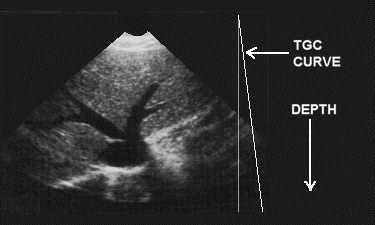
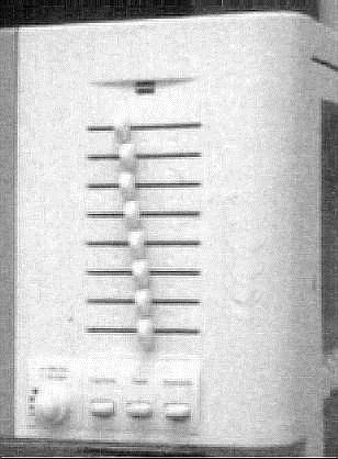
7 TIME GAIN COMPENSATION
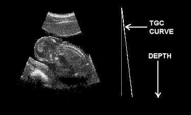
8 TIME GAIN COMPENSATION

9 GAIN vs. OUTPUT

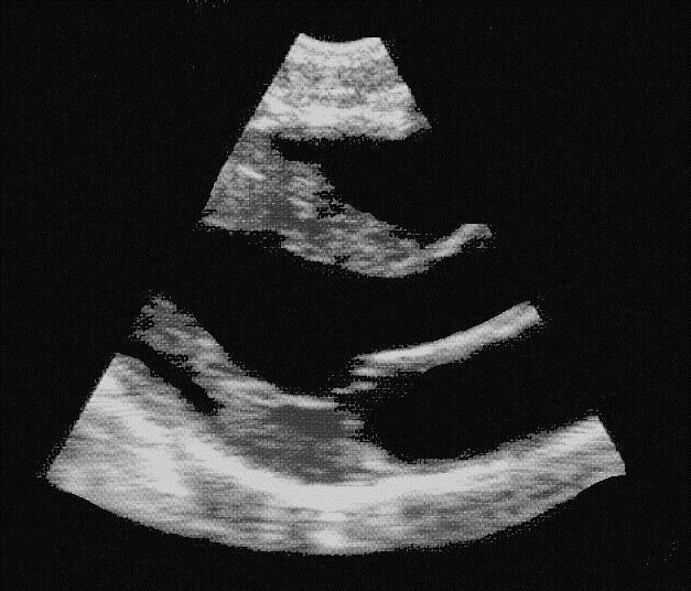
10 TGC INCORRECT SETTINGS

11 DYNAMIC RANGE DYNAMIC RANGE COMPRESSION LOG COMPRESSION COMPRESS

12 DYNAMIC RANGE 50 db 30 db
 anechoic BEFORE REJECT AFTER")
13 NOISE REDUCTION REJECT low-level echoes (noise) anechoic BEFORE REJECT AFTER REJECT
14 NOISE REDUCTION Frame averaging (persistence) Frequency compounding Spatial compounding
15 HARMONICS A wave whose frequency is a whole-number multiple of that of another

16 DISPLAY MODES

")
17 2D & M-mode B-SCAN (2-D) M-MODE
18 B-scan
19 B-scan
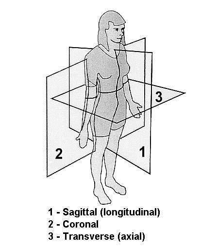
20 PATIENT-ORIENTED B-SCAN PLANES
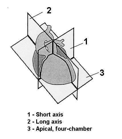
21 ORGAN-ORIENTED B-SCAN PLANES

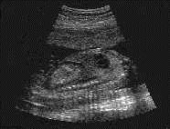
22 B-SCAN WITH A-SCAN OPHTHALMIC IMAGE
23 OBSTETRICAL IMAGES 2D 3D
24 Answers to the following FIFTEEN practice questions were derived from material in the textbook:
25 Question 1 Which of the following controls is part of the receiver in a pulse-echo ultrasound system? BRIGHTNESS XMTR PWR RES TGC POST PROCESSING Page 28
26 Question 1 Which of the following controls is part of the receiver in a pulse-echo ultrasound system? BRIGHTNESS XMTR PWR RES TGC POST PROCESSING Page 28
27 Question 2 The sensitivity of an ultrasound system may be determined by measuring the duty factor strongest echoes that are received bandwidth amplitude range of the received echoes weakest echoes that are received Page 27
28 Question 2 The sensitivity of an ultrasound system may be determined by measuring the duty factor strongest echoes that are received bandwidth amplitude range of the received echoes weakest echoes that are received Page 27
29 Question 3 If the OVERALL GAIN is decreased, only the brightness of the near echoes will decrease the energy to the patient is decreased the brightness of all echoes will decrease equally the frequency will decrease only the brightness of the far echoes will decrease Page 28
30 Question 3 If the OVERALL GAIN is decreased, only the brightness of the near echoes will decrease the energy to the patient is decreased the brightness of all echoes will decrease equally the frequency will decrease only the brightness of the far echoes will decrease Page 28
31 Question 4 If the ultrasound system displays only the echoes from strong reflectors and nothing else, the sonographer should increase the lateral resolution decrease the output power increase the overall gain decrease the slope of the TGC adjust the far gain Page 28
32 Question 4 If the ultrasound system displays only the echoes from strong reflectors and nothing else, the sonographer should increase the lateral resolution decrease the output power increase the overall gain decrease the slope of the TGC adjust the far gain Page 28
33 Question 5 The control that is used to suppress unwanted, low level echoes or background information is TGC POST PROCESSING DYNAMIC RANGE REJECT WRITE MAGNIFICATION Page 29
34 Question 5 The control that is used to suppress unwanted, low level echoes or background information is TGC POST PROCESSING DYNAMIC RANGE REJECT WRITE MAGNIFICATION Page 29
35 Question 6 Electrical interference could appear in an image as shadowing behind a poorly attenuating structure a decrease in far field penetration enhancement behind a highly reflective structure low-level echoes within a cyst a loss of axial resolution Page 29
36 Question 6 Electrical interference could appear in an image as shadowing behind a poorly attenuating structure a decrease in far field penetration enhancement behind a highly reflective structure low-level echoes within a cyst a loss of axial resolution Page 29
37 Question 7 The receiver dynamic range that provides the best opportunity for the display of a wide range of gray shades is 3 db 6 db 9 db 60 db 0 db Page 29
38 Question 7 The receiver dynamic range that provides the best opportunity for the display of a wide range of gray shades is 3 db 6 db 9 db 60 db 0 db Page 29
39 Question 8 Compression is used in the receiver of an ultrasound system to reduce the duty factor increase the difference between small and large amplitude signals reduce the range of signal amplitudes provide post processing reduce the sound energy entering the patient Page 29
40 Question 8 Compression is used in the receiver of an ultrasound system to reduce the duty factor increase the difference between small and large amplitude signals reduce the range of signal amplitudes provide post processing reduce the sound energy entering the patient Page 29
41 Question 9 The OUTPUT control on a pulse-echo ultrasound system controls the amount of amplification in the receiver varies the dynamic range in the receiver is used to equalize differences in received echo amplitudes due to differences in the depths of the reflectors varies the voltage that the beamformer supplies to the transducer does not have any affect on the amount of sound energy that enters a patient Page 26
42 Question 9 The OUTPUT control on a pulse-echo ultrasound system controls the amount of amplification in the receiver varies the dynamic range in the receiver is used to equalize differences in received echo amplitudes due to differences in the depths of the reflectors varies the voltage that the beamformer supplies to the transducer does not have any affect on the amount of sound energy that enters a patient Page 26
43 Question 10 The OUTPUT control in a pulse-echo system does NOT affect the excitation voltage that is applied to the transducer frequency of the sound that leaves the transducer energy that enters the patient amount of energy leaving a transducer overall gain that may be required Page 26
44 Question 10 The OUTPUT control in a pulse-echo system does NOT affect the excitation voltage that is applied to the transducer frequency of the sound that leaves the transducer energy that enters the patient amount of energy leaving a transducer overall gain that may be required Page 26
45 Question 11 From a safety standpoint, which one of the following methods is BEST? Low transmitter output and high receiver gain High near gain and low far gain High reject and high transmitter output High transmitter output and low receiver gain Low near gain and high far gain Page 28
46 Question 11 From a safety standpoint, which one of the following methods is BEST? Low transmitter output and high receiver gain High near gain and low far gain High reject and high transmitter output High transmitter output and low receiver gain Low near gain and high far gain Page 28
47 Question 12 The dynamic range of the receiver of an ultrasound system refers to the ability of the receiver to track a rapidly moving structure range of echo signal frequencies that can be processed without distortion speed with which the receiver recovers following the excitation pulse to the transducer depth range in tissue over which moving echoes can be received range of echo signal amplitudes that can be processed without distortion Page 29
48 Question 12 The dynamic range of the receiver of an ultrasound system refers to the ability of the receiver to track a rapidly moving structure range of echo signal frequencies that can be processed without distortion speed with which the receiver recovers following the excitation pulse to the transducer depth range in tissue over which moving echoes can be received range of echo signal amplitudes that can be processed without distortion Page 29
49 Question 13 Which of the following results in an increased acoustic exposure to the patient? application of reject increase in the swept gain slope rate increase in the television monitor brightness increase in the beamformer voltage to the transducer increase in the overall gain Page 26
50 Question 13 Which of the following results in an increased acoustic exposure to the patient? application of reject increase in the swept gain slope rate increase in the television monitor brightness increase in the beamformer voltage to the transducer increase in the overall gain Page 26
51 Question 14 Which of the following is NOT a brightness-modulated display, based on the amplitude of received echoes? B mode B scan A mode Real time gray scale M mode Page 31
52 Question 14 Which of the following is NOT a brightness-modulated display, based on the amplitude of received echoes? B mode B scan A mode Real time gray scale M mode Page 31
53 Question 15 Increasing the gain of a pulse-echo system results in higher A-mode echoes. This is due to increased amount of sound emitted by the transducer increased amount of sound reflected increased efficiency of transducer conversion of sound into electricity increased amplification in the receiver decreased amplification in the receiver Pages 28 and 31
54 Question 15 Increasing the gain of a pulse-echo system results in higher A-mode echoes. This is due to increased amount of sound emitted by the transducer increased amount of sound reflected increased efficiency of transducer conversion of sound into electricity increased amplification in the receiver decreased amplification in the receiver Pages 28 and 31
55 END OF LESSON 06 For information on the accompanying textbook, visit the Website:
Lesson 06: Pulse-echo Imaging and Display Modes. These lessons contain 26 slides plus 15 multiple-choice questions.
 Lesson 06: Pulse-echo Imaging and Display Modes These lessons contain 26 slides plus 15 multiple-choice questions. These lesson were derived from pages 26 through 32 in the textbook: ULTRASOUND IMAGING
Answer: TGC is needed to amplify echoes from deeper structures so that they appear as bright as similar structures located at more shallow depths.
 Q47. When performing a sonogram why the sonographer needs to use the TGC? TGC is needed to amplify echoes from deeper structures so that they appear as bright as similar structures located at more shallow
Ultrasound Beamforming and Image Formation. Jeremy J. Dahl
 Ultrasound Beamforming and Image Formation Jeremy J. Dahl Overview Ultrasound Concepts Beamforming Image Formation Absorption and TGC Advanced Beamforming Techniques Synthetic Receive Aperture Parallel
Optimisation of Image Acquisition Bordeaux 16th November J.S. McGhie W.B. Vletter R. Frowijn No disclosures
 Optimisation of Image Acquisition Bordeaux 16th November 2016 J.S. McGhie W.B. Vletter R. Frowijn No disclosures Image optimisation: The Echo machine It looks difficult to drive an echo machine!! Some
Lesson 02: Sound Wave Production. This lesson contains 24 slides plus 11 multiple-choice questions.
 Lesson 02: Sound Wave Production This lesson contains 24 slides plus 11 multiple-choice questions. Accompanying text for the slides in this lesson can be found on pages 2 through 7 in the textbook: ULTRASOUND
The Physics of Echo. The Physics of Echo. The Physics of Echo Is there pericardial calcification? 9/30/13
 Basic Ultrasound Physics Kirk Spencer MD Speaker has no disclosures to make Sound Audible range 20Khz Medical ultrasound Megahertz range Advantages of imaging with ultrasound Directed as a beam Tomographic
Artifacts. Artifacts. Causes. Imaging assumptions. Common terms used to describe US images. Common terms used to describe US images
 Artifacts Artifacts Chapter 20 What are they? Simply put they are an error in imaging These artifacts include reflections that are: not real incorrect shape, size or position incorrect brightness displayed
Physics of Ultrasound Ultrasound Imaging and Artifacts รศ.นพ.เดโช จ กราพาน ชก ล สาขาหท ยว ทยา, ภาคว ชาอาย รศาสตร คณะแพทยศาสตร ศ ร ราชพยาบาล
 Physics of Ultrasound Ultrasound Imaging and Artifacts รศ.นพ.เดโช จ กราพาน ชก ล สาขาหท ยว ทยา, ภาคว ชาอาย รศาสตร คณะแพทยศาสตร ศ ร ราชพยาบาล Diagnosis TTE TEE ICE 3D 4D Evaluation of Cardiac Anatomy Hemodynamic
Pass Ultrasound Physics Exam
 Pass Ultrasound Physics Exam Match the Answers By Mansoor Khan MBBS, RDMS, RDCS 1 Copyright 2014 Blue Cube Venture, LLC All rights reserved. The Pass Ultrasound Physics Exam Match the Answers is protected
Ultrasound & Artifacts
 ISSN 2005-7881 Journal of Neurosonology 3(Suppl. 2):1-17, 2011 Ultrasound & Artifacts Siryung Han The Catholic University of Korea Artifacts False image- echoes without anatomic correlate US image dose
The Middle East Distributor for AMBISEA Technology Corp. Electro-Medical Product Line
 The Middle East Distributor for AMBISEA Technology Corp. Electro-Medical Product Line AV-9100 Single Channel ECG 1 2 AV-9300 3-Channels ECG 3 4 5 AV-9000B Multi-Parameter Patient Monitor 6 7 8 AV-9000C
12/26/2017. Alberto Ardon M.D.
 Alberto Ardon M.D. 1 Preparatory Work Ultrasound Physics http://www.nysora.com/mobile/regionalanesthesia/foundations-of-us-guided-nerve-blockstechniques/index.1.html Basic Ultrasound Handling https://www.youtube.com/watch?v=q2otukhrruc
Chapter 4. Pulse Echo Imaging. where: d = distance v = velocity t = time
 Chapter 4 Pulse Echo Imaging Ultrasound imaging systems are based on the principle of pulse echo imaging. These systems require the use of short pulses of ultrasound to create two-dimensional, sectional
Ultrasound Imaging Ultr Michael Dadd 2007
 Ultrasound Imaging Ultrasound Physics & Instrumentation - Recommended Reading 1. Diagnostic Ultrasound: Principles and Instruments (7th Ed) Frederick W Kremkau W B Saunders Company 2. Applied Physics &
Introduction to Ultrasound Physics
 Introduction to Ultrasound Physics Vassilis Sboros Medical Physics and Cardiovascular Sciences University of Edinburgh Transverse waves Water remains in position Disturbance traverse producing more wave
Introduction. Parametric Imaging. The Ultrasound Research Interface: A New Tool for Biomedical Investigations
 The Ultrasound Research Interface: A New Tool for Biomedical Investigations Shelby Brunke, Laurent Pelissier, Kris Dickie, Jim Zagzebski, Tim Hall, Thaddeus Wilson Siemens Medical Systems, Issaquah WA
MAKING TRANSIENT ANTENNA MEASUREMENTS
 MAKING TRANSIENT ANTENNA MEASUREMENTS Roger Dygert, Steven R. Nichols MI Technologies, 1125 Satellite Boulevard, Suite 100 Suwanee, GA 30024-4629 ABSTRACT In addition to steady state performance, antennas
Ultrasound Physics. History: Ultrasound 2/13/2019. Ultrasound
 Ultrasound Physics History: Ultrasound Ultrasound 1942: Dr. Karl Theodore Dussik transmission ultrasound investigation of the brain 1949-51: Holmes and Howry subject submerged in water tank to achieve
Ultrasound physical principles in today s technology
 Education Ultrasound physical principles in today s technology Brian Starkoff M.App.Sc.(Med. Ultrasound), AMS Holland Park Brisbane Queensland Australia Correspondence to email starkoff@optusnet.com.au
The physics of ultrasound. Dr Graeme Taylor Guy s & St Thomas NHS Trust
 The physics of ultrasound Dr Graeme Taylor Guy s & St Thomas NHS Trust Physics & Instrumentation Modern ultrasound equipment is continually evolving This talk will cover the basics What will be covered?
3. Ultrasound Imaging(2)
") 3. Ultrasound Imaging(2) Lecture 13, 14 Medical Imaging Systems Jae Gwan Kim, Ph.D. jaekim@gist.ac.kr, X 2220 Department of BioMedical Science and Engineering Gwangju Institute of Sciences and Technology
3. Ultrasound Imaging(2) Lecture 13, 14 Medical Imaging Systems Jae Gwan Kim, Ph.D. jaekim@gist.ac.kr, X 2220 Department of BioMedical Science and Engineering Gwangju Institute of Sciences and Technology
CHAPTER 1 INTRODUCTION
 CHAPTER 1 INTRODUCTION Spatial resolution in ultrasonic imaging is one of many parameters that impact image quality. Therefore, mechanisms to improve system spatial resolution could result in improved
Image Optimization: The Sonographer s Responsibility. Prepared by Cathy Daniels, EdD, RTR, RDMS, RDCS, RVT
 Image Optimization: The Sonographer s Responsibility Prepared by Cathy Daniels, EdD, RTR, RDMS, RDCS, RVT Image Optimization: The Sonographer s Responsibility Cathy Daniels, EdD, RTR, RDMS, RDCS, RVT Disclosure
Lecture 6 SIGNAL PROCESSING. Radar Signal Processing Dr. Aamer Iqbal Bhatti. Dr. Aamer Iqbal Bhatti
 Lecture 6 SIGNAL PROCESSING Signal Reception Receiver Bandwidth Pulse Shape Power Relation Beam Width Pulse Repetition Frequency Antenna Gain Radar Cross Section of Target. Signal-to-noise ratio Receiver
Physics of ultrasound
 1 Physics of ultrasound Basic principles Nature of ultrasound Sound = longitudinal, mechanical wave particles move parallel to direction of travel Audible sound < 20 khz Ultrasound > 20 khz Sound cannot
Chapter-15. Communication systems -1 mark Questions
 Chapter-15 Communication systems -1 mark Questions 1) What are the three main units of a Communication System? 2) What is meant by Bandwidth of transmission? 3) What is a transducer? Give an example. 4)
White Rose Research Online URL for this paper: Version: Accepted Version
 This is a repository copy of Enhancement of contrast and resolution of B-mode plane wave imaging (PWI) with non-linear filtered delay multiply and sum () beamforming. White Rose Research Online URL for
Television and video engineering
 Television and video engineering Unit-4 Television Receiver systems Objectives: To learn the requirements of TV receiver Study of monochrome and Colour TV receivers. To learn functions of Tuning circuits
Lesson 12: Doppler Principles. This lesson contains 50 slides plus 26 multiple-choice questions.
 Lesson 12: Doppler Principles This lesson contains 50 slides plus 26 multiple-choice questions. Accompanying text for the slides in this lesson can be found on pages 59 through 80 in the textbook: DOPPLER
Ultrasound Bioinstrumentation. Topic 2 (lecture 3) Beamforming
 Beamforming") Ultrasound Bioinstrumentation Topic 2 (lecture 3) Beamforming Angular Spectrum 2D Fourier transform of aperture Angular spectrum Propagation of Angular Spectrum Propagation as a Linear Spatial Filter Free
Ultrasound Bioinstrumentation Topic 2 (lecture 3) Beamforming Angular Spectrum 2D Fourier transform of aperture Angular spectrum Propagation of Angular Spectrum Propagation as a Linear Spatial Filter Free
4 Working With Scan Modes
 4 Working With Scan Modes Scan Modes Overview All of the information in this chapter pertains to live imaging. Many of the controls and functions change when you freeze the scan. For information on using
Nuove tecnologie per ecografia ad ultrasuoni: da 2D a 4D
 DINFO Dipartimento di Ingegneria dell Informazione Department of Information Engineering Nuove tecnologie per ecografia ad ultrasuoni: da 2D a 4D Piero Tortoli Microelectronics Systems Design Lab 1 Introduction
Medical Imaging. X-rays, CT/CAT scans, Ultrasound, Magnetic Resonance Imaging
 Medical Imaging X-rays, CT/CAT scans, Ultrasound, Magnetic Resonance Imaging From: Physics for the IB Diploma Coursebook 6th Edition by Tsokos, Hoeben and Headlee And Higher Level Physics 2 nd Edition
Sonic Distance Sensors
 Sonic Distance Sensors Introduction - Sound is transmitted through the propagation of pressure in the air. - The speed of sound in the air is normally 331m/sec at 0 o C. - Two of the important characteristics
Real Time Deconvolution of In-Vivo Ultrasound Images
 Paper presented at the IEEE International Ultrasonics Symposium, Prague, Czech Republic, 3: Real Time Deconvolution of In-Vivo Ultrasound Images Jørgen Arendt Jensen Center for Fast Ultrasound Imaging,
Breast Ultrasound QA Phantom Recommended by Japan Association of Breast and Thyroid Sonology
 Breast Ultrasound QA Phantom Recommended by Japan Association of Breast and Thyroid Sonology Product supervision: Japan Association of Breast and Thyroid Sonology, Quality Assurance Committee Working Team.
Multi-Element Synthetic Transmit Aperture Method in Medical Ultrasound Imaging Ihor Trots, Yuriy Tasinkevych, Andrzej Nowicki and Marcin Lewandowski
 Multi-Element Synthetic Transmit Aperture Method in Medical Ultrasound Imaging Ihor Trots, Yuriy Tasinkevych, Andrzej Nowicki and Marcin Lewandowski Abstract The paper presents the multi-element synthetic
Physics of Ultrasound & Doppler. Sang Jae Rhee. MD., PhD. Division of Cardiovascular Medicine Wonkwang University Hospital
 Physics of Ultrasound & Doppler Sang Jae Rhee. MD., PhD. Division of Cardiovascular Medicine Wonkwang University Hospital Classification of Sound Infrasound Audible sound Ultrasound < 20 Hz 20-20,000 Hz
Lecture 3: Data Transmission
 Lecture 3: Data Transmission 1 st semester 1439-2017 1 By: Elham Sunbu OUTLINE Data Transmission DATA RATE LIMITS Transmission Impairments Examples DATA TRANSMISSION The successful transmission of data
Physics in Modern Medicine Fall 2010
 Physics in Modern Medicine Fall 2010 Homework #3 Chapter 3 Lasers in Medicine Questions Q3.1 Absorption in melanin increases with decreasing wavelength, and has a maximum, according to figure 3.23 in the
Medical Imaging (EL582/BE620/GA4426)
") Medical Imaging (EL582/BE620/GA4426) Jonathan Mamou, PhD Riverside Research Lizzi Center for Biomedical Engineering New York, NY jmamou@riversideresearch.org On behalf of Prof. Daniel Turnbull Outline
Medical Imaging (EL582/BE620/GA4426) Jonathan Mamou, PhD Riverside Research Lizzi Center for Biomedical Engineering New York, NY jmamou@riversideresearch.org On behalf of Prof. Daniel Turnbull Outline
Principles of Ultrasound Imaging Image Optimization
 Principles of Ultrasound Imaging Image Optimization Robert A. Levine, MD, FACE, ECNU Thyroid Center of New Hampshire Geisel School of Medicine at Dartmouth College Disclosures: No relevant financial or
Photomultiplier Tube
 Nuclear Medicine Uses a device known as a Gamma Camera. Also known as a Scintillation or Anger Camera. Detects the release of gamma rays from Radionuclide. The radionuclide can be injected, inhaled or
Evaluation of automatic time gain compensated in-vivo ultrasound sequences
 Downloaded from orbit.dtu.dk on: Dec 19, 17 Evaluation of automatic time gain compensated in-vivo ultrasound sequences Axelsen, Martin Christian; Røeboe, Kristian Frostholm; Hemmsen, Martin Christian;
Interaction of Sound and. logarithms. Logarithms continued. Decibels (db) Decibels (db) continued. Interaction of Sound and Media continued
 Decibels (db) continued. Interaction of Sound and Media continued") Interaction of Sound and Media continued Interaction of Sound and Media Chapter 6 As sound travels through a media and interacts with normal anatomical structures its intensity weakens through what is
Interaction of Sound and Media continued Interaction of Sound and Media Chapter 6 As sound travels through a media and interacts with normal anatomical structures its intensity weakens through what is
Lecture 19. Ultrasound Imaging
 Lecture 19 Ultrasound Imaging Contents 1. Introduction 2. Ultrasound and its generation 3. Wave propagation in the matter 4. Data acquisition (A, B, M and Doppler model) 5. Imaging reconstruction (5 steps)
Performing ultrasound probe quality assurance assessments: A How-to Guide
 Performing ultrasound probe quality assurance assessments: A How-to Guide A comprehensive quality assurance program has the potential to directly contribute to better patient outcomes. Regular testing
COMPUTER PHANTOMS FOR SIMULATING ULTRASOUND B-MODE AND CFM IMAGES
 Paper presented at the 23rd Acoustical Imaging Symposium, Boston, Massachusetts, USA, April 13-16, 1997: COMPUTER PHANTOMS FOR SIMULATING ULTRASOUND B-MODE AND CFM IMAGES Jørgen Arendt Jensen and Peter
Ques on (2): [18 Marks] a) Draw the atrial synchronous Pacemaker block diagram and explain its operation. Benha University June 2013
![Ques on (2): [18 Marks] a) Draw the atrial synchronous Pacemaker block diagram and explain its operation. Benha University June 2013](/thumbs/87/96832478.jpg "Ques on (2): [18 Marks] a) Draw the atrial synchronous Pacemaker block diagram and explain its operation. Benha University June 2013") Benha University June 2013 Benha Faculty of Engineering Electrical Department Hospital Instrumentations (E472) 4 Th year (control) Dr.Waleed Abdel Aziz Salem Time: 3 Hrs Answer the following questions.
Benha University June 2013 Benha Faculty of Engineering Electrical Department Hospital Instrumentations (E472) 4 Th year (control) Dr.Waleed Abdel Aziz Salem Time: 3 Hrs Answer the following questions.
An Overview Algorithm to Minimise Side Lobes for 2D Circular Phased Array
 An Overview Algorithm to Minimise Side Lobes for 2D Circular Phased Array S. Mondal London South Bank University; School of Engineering 103 Borough Road, London SE1 0AA More info about this article: http://www.ndt.net/?id=19093
We are IntechOpen, the world s leading publisher of Open Access books Built by scientists, for scientists. International authors and editors
 We are IntechOpen, the world s leading publisher of Open Access books Built by scientists, for scientists 4, 6, 2M Open access books available International authors and editors Downloads Our authors are
Chapter 3, Sections Electrical Filters
 Chapter 3, Sections 3.2.4-3.2.5 Electrical Filters Signals DC and AC Components - Many signals can be constructed as sums of AC and DC components: 2.5 2 1.5 2 1.5 1.5 1 2 3 4 1.5 -.5-1 1 2 3 4 = + 2.5
Keywords: Ultrasonic Testing (UT), Air-coupled, Contact-free, Bond, Weld, Composites
, Air-coupled, Contact-free, Bond, Weld, Composites") Single-Sided Contact-Free Ultrasonic Testing A New Air-Coupled Inspection Technology for Weld and Bond Testing M. Kiel, R. Steinhausen, A. Bodi 1, and M. Lucas 1 Research Center for Ultrasonics - Forschungszentrum
Single-Sided Contact-Free Ultrasonic Testing A New Air-Coupled Inspection Technology for Weld and Bond Testing M. Kiel, R. Steinhausen, A. Bodi 1, and M. Lucas 1 Research Center for Ultrasonics - Forschungszentrum
L(f) = = (f) G(f) L2(f) Transmission Impairments: Attenuation (cont.)
 = = (f) G(f) L2(f) Transmission Impairments: Attenuation (cont.)") Transmission Impairments: Attenuation (cont.) how many times the put signal has attenuated relative to the input signal should be in L(f) (f) (f) A A in (f) (f) how many times the put signal has been amplified
Transmission Impairments: Attenuation (cont.) how many times the put signal has attenuated relative to the input signal should be in L(f) (f) (f) A A in (f) (f) how many times the put signal has been amplified
Data Communication. Chapter 3 Data Transmission
 Data Communication Chapter 3 Data Transmission ١ Terminology (1) Transmitter Receiver Medium Guided medium e.g. twisted pair, coaxial cable, optical fiber Unguided medium e.g. air, water, vacuum ٢ Terminology
B-mode imaging components
 Peter Pazmany Catholic University Faculty of Information Technology www.itk.ppke.hu Medical diagnostic systems (Orvosbiológiai képalkotó rendszerek) B-mode imaging components ( B-mód képalkotás összetevői)
Chapter 2 Channel Equalization
 Chapter 2 Channel Equalization 2.1 Introduction In wireless communication systems signal experiences distortion due to fading [17]. As signal propagates, it follows multiple paths between transmitter and
Further development of synthetic aperture real-time 3D scanning with a rotating phased array
 Downloaded from orbit.dtu.dk on: Dec 17, 217 Further development of synthetic aperture real-time 3D scanning with a rotating phased array Nikolov, Svetoslav; Tomov, Borislav Gueorguiev; Gran, Fredrik;
Current consumption from V CC1 and V EE1 (per channel), MAX4805 V CC1 = -V EE1 = +2V, V CC2 = -V EE2 = +5V. Current consumption from MAX4805A
, MAX4805 V CC1 = -V EE1 = +2V, V CC2 = -V EE2 = +5V. Current consumption from MAX4805A") /A General Description The /A are octal high-voltage-protected operational amplifiers. These devices are a fully integrated, very compact solution for in-probe amplification of echo signals coming from
/A General Description The /A are octal high-voltage-protected operational amplifiers. These devices are a fully integrated, very compact solution for in-probe amplification of echo signals coming from
Course Code: EE-411 Teacher: Engr.Ahmad Bilal Multiple choice & Short Questions notes
 Department of Electrical (POWER) Engineering Swedish College of Engineering & Technology Rahim yar khan Subject: Communication systems Course Code: EE-411 Teacher: Engr.Ahmad Bilal Multiple choice & Short
Technical Datasheet UltraScope USB
 Technical Datasheet UltraScope USB www.daselsistemas.com Revision INDEX 1 CHANNELS... 3 2 PULSER... 3 3 RECEIVER... 4 4 FILTERS... 4 5 TRIGGER MODES... 5 6 SIGNAL PROCESSING... 5 7 CONTROL SIGNALS... 6
Analog Circuits and Systems
 Analog Circuits and Systems Prof. K Radhakrishna Rao Lecture 21: Filters 1 Review Integrators as building blocks of filters Frequency compensation in negative feedback systems Opamp and LDO frequency compensation
Chapter 3 Digital Transmission Fundamentals
 Chapter 3 Digital Transmission Fundamentals Why Digital Communications? CSE 3213, Winter 2010 Instructor: Foroohar Foroozan A Transmission System Transmitter Receiver Communication channel Transmitter
ULTRASONIC IMAGING of COPPER MATERIAL USING HARMONIC COMPONENTS
 ULTRASONIC IMAGING of COPPER MATERIAL USING HARMONIC COMPONENTS T. Stepinski P. Wu Uppsala University Signals and Systems P.O. Box 528, SE- 75 2 Uppsala Sweden ULTRASONIC IMAGING of COPPER MATERIAL USING
INTRODUCTION. Have applications for imaging, detection and navigation.
 ULTRASONICS INTRODUCTION The word ultrasonic combines the Latin roots ultra - beyond sonic - sound. Having frequencies above the audible range i.e. above 20000Hz Have applications for imaging, detection
Key Physics and Doppler Principles
 Key Physics and Doppler Principles Robert A. Levine, MD, FACE, ECNU Thyroid Center of New Hampshire Geisel School of Medicine at Dartmouth College AACE/ACE Advanced Neck Ultrasound Training Course Disclosures:
RADIO RECEIVERS ECE 3103 WIRELESS COMMUNICATION SYSTEMS
 RADIO RECEIVERS ECE 3103 WIRELESS COMMUNICATION SYSTEMS FUNCTIONS OF A RADIO RECEIVER The main functions of a radio receiver are: 1. To intercept the RF signal by using the receiver antenna 2. Select the
HF Receivers, Part 2
 HF Receivers, Part 2 Superhet building blocks: AM, SSB/CW, FM receivers Adam Farson VA7OJ View an excellent tutorial on receivers NSARC HF Operators HF Receivers 2 1 The RF Amplifier (Preamp)! Typical
Some key functions implemented in the transmitter are modulation, filtering, encoding, and signal transmitting (to be elaborated)
") 1 An electrical communication system enclosed in the dashed box employs electrical signals to deliver user information voice, audio, video, data from source to destination(s). An input transducer may be
1 An electrical communication system enclosed in the dashed box employs electrical signals to deliver user information voice, audio, video, data from source to destination(s). An input transducer may be
Propagation of Electromagnetic Waves
 Propagation of Electromagnetic Waves REFLECTOR (Water) RADAR ANTENNA Speed of electromagnetic waves used in radar = 300,000,000m/s Speed of electromagnetic waves changes due to temperature, pressure and
IPC TECHNICAL PAPER SERIES NUMBER 310
 THE INSTITUTE OF PAPER CHEMISTRY, APPLETON, WISCONSIN IPC TECHNICAL PAPER SERIES NUMBER 310 THE DEVELOPMENT OF A DOUBLE ELEMENT, PULSE ECHO, PVDF TRANSDUCER C. C. HABEGER AND W. A. WINK DECEMBER, 1988
APPLYING SYNTHETIC APERTURE, CODED EXCITATION, AND TISSUE HARMONIC IMAGING TECHNIQUES TO ALLOW ULTRASOUND IMAGING WITH A VIRTUAL SOURCE ROBYN T.
 APPLYING SYNTHETIC APERTURE, CODED EXCITATION, AND TISSUE HARMONIC IMAGING TECHNIQUES TO ALLOW ULTRASOUND IMAGING WITH A VIRTUAL SOURCE BY ROBYN T. UMEKI THESIS Submitted in partial fulfillment of the
CHAPTER -15. Communication Systems
 CHAPTER -15 Communication Systems COMMUNICATION Communication is the act of transmission and reception of information. COMMUNICATION SYSTEM: A system comprises of transmitter, communication channel and
UNIT-1. Basic signal processing operations in digital communication
 UNIT-1 Lecture-1 Basic signal processing operations in digital communication The three basic elements of every communication systems are Transmitter, Receiver and Channel. The Overall purpose of this system
Real-time B-mode ultrasound quality control test procedures a Report of AAPM Ultrasound Task Group No. 1
 Real-time B-mode ultrasound quality control test procedures a Report of AAPM Ultrasound Task Group No. 1 Mitchell M. Goodsitt b) and Paul L. Carson Department of Radiology, University of Michigan, Ann
NEW YORK CITY COLLEGE of TECHNOLOGY THE CITY UNIVERSITY OF NEW YORK DEPARTMENT OF ELECTRICAL ENGINEERING AND TELECOMMUNICATIONS TECHNOLOGIES
 NEW YORK CITY COLLEGE of TECHNOLOGY THE CITY UNIVERSITY OF NEW YORK DEPARTMENT OF ELECTRICAL ENGINEERING AND TELECOMMUNICATIONS TECHNOLOGIES Course : EET 24 Communications Electronics Module : AM Tx and
Attenuation and velocity of ultrasound in solid state materials (transmission)
") Attenuation and velocity of ultrasound in solid 5.1.6.08 Related Topics Propagation of ultrasonic waves, time of flight, sound velocity, damping of ultrasonic waves (scattering, reflection, absorption),
Attenuation and velocity of ultrasound in solid 5.1.6.08 Related Topics Propagation of ultrasonic waves, time of flight, sound velocity, damping of ultrasonic waves (scattering, reflection, absorption),
INTEGRATED CIRCUITS DATA SHEET. TDA1596 IF amplifier/demodulator for FM radio receivers. Product specification File under Integrated Circuits, IC01
 INTEGRATED CIRCUITS DATA SHEET File under Integrated Circuits, IC01 April 1991 GENERAL DESCRIPTION The provides IF amplification, symmetrical quadrature demodulation and level detection for quality home
Data and Computer Communications Chapter 3 Data Transmission
 Data and Computer Communications Chapter 3 Data Transmission Eighth Edition by William Stallings Transmission Terminology data transmission occurs between a transmitter & receiver via some medium guided
PULSE ECHO ULTRASOUND IMAGING SYSTEMS: PERFORMANCE TESTS AND CRITERIA
 AAPM REPORT No. 8 PULSE ECHO ULTRASOUND IMAGING SYSTEMS: PERFORMANCE TESTS AND CRITERIA Published for the American Association of Physicists in Medicine by the American Institute of Physics AAPM REPORT
ACOUSTIC MICRO IMAGING ANALYSIS METHODS FOR 3D PACKAGES
 ACOUSTIC MICRO IMAGING ANALYSIS METHODS FOR 3D PACKAGES Janet E. Semmens Sonoscan, Inc. Elk Grove Village, IL, USA Jsemmens@sonoscan.com ABSTRACT Earlier studies concerning evaluation of stacked die packages
SECTION I - CHAPTER 2 DIGITAL IMAGING PROCESSING CONCEPTS
 RADT 3463 - COMPUTERIZED IMAGING Section I: Chapter 2 RADT 3463 Computerized Imaging 1 SECTION I - CHAPTER 2 DIGITAL IMAGING PROCESSING CONCEPTS RADT 3463 COMPUTERIZED IMAGING Section I: Chapter 2 RADT
Characteristics of HF Coastal Radars
 Function Characteristics System 1 Maximum operational (measurement) range** Characteristics of HF Coastal Radars 5 MHz Long-range oceanographic 160-220 km average during (daytime)* System 2 System 3 System
Lecture 2 Physical Layer - Data Transmission
 DATA AND COMPUTER COMMUNICATIONS Lecture 2 Physical Layer - Data Transmission Mei Yang Based on Lecture slides by William Stallings 1 DATA TRANSMISSION The successful transmission of data depends on two
Interference & Suppression Page 59
 INTERFERENCE Interference & Suppression Page 59 Front-End Overload, Cross-Modulation What is meant by receiver overload? Interference caused by strong signals from a nearby transmitter What is one way
Exercise 1-3. Radar Antennas EXERCISE OBJECTIVE DISCUSSION OUTLINE DISCUSSION OF FUNDAMENTALS. Antenna types
 Exercise 1-3 Radar Antennas EXERCISE OBJECTIVE When you have completed this exercise, you will be familiar with the role of the antenna in a radar system. You will also be familiar with the intrinsic characteristics
Technician License Course Chapter 3. Lesson Plan Module 7 Types of Radio Circuits
 Technician License Course Chapter 3 Lesson Plan Module 7 Types of Radio Circuits The Basic Transceiver Combination of transmitter and receiver Abbreviated XCVR (X = trans) Antenna switched between transmitter
Exercise 2: Simulation of ultrasound field using Field II
 Exercise 2: Simulation of ultrasound field using Field II The purposes of this exercise is to learn how to: Set up the simulation environment and model a transducer in Field II o Single element transducer
THE INFLUENCE OF THE TRANSDUCER BANDWIDTH AND DOUBLE PULSE TRANSMISSION ON THE ENCODED IMAGING ULTRASOUND
 THE INFLUENCE OF THE TRANSDUCER BANDWIDTH AND DOUBLE PULSE TRANSMISSION ON THE ENCODED IMAGING ULTRASOUND IHOR TROTS, ANDRZEJ NOWICKI, MARCIN LEWANDOWSKI, WOJCIECH SECOMSKI, JERZY LITNIEWSKI Institute
Keysight Technologies Pulsed Antenna Measurements Using PNA Network Analyzers
 Keysight Technologies Pulsed Antenna Measurements Using PNA Network Analyzers White Paper Abstract This paper presents advances in the instrumentation techniques that can be used for the measurement and
Module 8 Theory. dbs AM Detector Ring Modulator Receiver Chain. Functional Blocks Parameters. IRTS Region 4
 Module 8 Theory dbs AM Detector Ring Modulator Receiver Chain Functional Blocks Parameters Decibel (db) The term db or decibel is a relative unit of measurement used frequently in electronic communications
Proceedings of Meetings on Acoustics
 Proceedings of Meetings on Acoustics Volume 19, 2013 http://acousticalsociety.org/ ICA 2013 Montreal Montreal, Canada 2-7 June 2013 Signal Processing in Acoustics Session 1pSPc: Miscellaneous Topics in
X-RAY IMAGING EE 472 F2017. Prof. Yasser Mostafa Kadah
 X-RAY IMAGING EE 472 F2017 Prof. Yasser Mostafa Kadah www.k-space.org Recommended Textbook Stewart C. Bushong, Radiologic Science for Technologists: Physics, Biology, and Protection, 10 th ed., Mosby,
IMAGING OF DEFECTS IN CONCRETE COMPONENTS WITH NON-CONTACT ULTRASONIC TESTING W. Hillger, DLR and Ing. Büro Dr. Hillger, Braunschweig, Germany
 IMAGING OF DEFECTS IN CONCRETE COMPONENTS WITH NON-CONTACT ULTRASONIC TESTING W. Hillger, DLR and Ing. Büro Dr. Hillger, Braunschweig, Germany Abstract: The building industries require NDT- methods for
Understanding How Frequency, Beam Patterns of Transducers, and Reflection Characteristics of Targets Affect the Performance of Ultrasonic Sensors
 Characteristics of Targets Affect the Performance of Ultrasonic Sensors By Donald P. Massa, President and CTO of Massa Products Corporation Overview of How an Ultrasonic Sensor Functions Ultrasonic sensors
1. The ray diagram shows the position and size of the image, I, of an object, O, formed by a lens, L.
 Medical applications of physics 1. The ray diagram shows the position and size of the image, I, of an object, O, formed by a lens, L. L O P I (a) What type of lens is shown in the ray diagram? Name the
Lecture 6. Angle Modulation and Demodulation
 Lecture 6 and Demodulation Agenda Introduction to and Demodulation Frequency and Phase Modulation Angle Demodulation FM Applications Introduction The other two parameters (frequency and phase) of the carrier
Introduction. sig. ref. sig
 Introduction A lock-in amplifier, in common with most AC indicating instruments, provides a DC output proportional to the AC signal under investigation. The special rectifier, called a phase-sensitive
Fig. 1
 PhysicsAndMathsTutor.com 1 1. Fig. 1 shows data for the intensity of a parallel beam of X-rays after penetration through varying thicknesses of a material. intensity / MW m 2 thickness / mm 0.91 0.40 0.69
Equipment for Attenuation and velocity of ultrasound in solid state materials (transmission), experimental set-up
, experimental set-up") Attenuation and velocity of ultrasound in solid TEAS Related Topics Propagation of ultrasonic waves, time of flight, sound velocity, damping of ultrasonic waves (scattering, reflection, absorption), transmission
Attenuation and velocity of ultrasound in solid TEAS Related Topics Propagation of ultrasonic waves, time of flight, sound velocity, damping of ultrasonic waves (scattering, reflection, absorption), transmission