Key Physics and Doppler Principles
|
|
|
- Norma Tucker
- 5 years ago
- Views:
Transcription

1 Key Physics and Doppler Principles Robert A. Levine, MD, FACE, ECNU Thyroid Center of New Hampshire Geisel School of Medicine at Dartmouth College AACE/ACE Advanced Neck Ultrasound Training Course
2 Disclosures: No relevant financial or corporate conflicts of interest. The use of investigational drugs will not be discussed
3 Image Optimization Create the sharpest image to allow tissue discrimination. Equipment factors: Quality of Transducer Quality of Electronics Image Enhancement and Compound Imaging User Adjustments: Depth, Gain, Frequency Focal zones Number and Location Compound Imaging Tissue Harmonic Imaging Dynamic range Doppler settings: Wall filter and PRF
4

5 Optimal Depth
 Adjustable depth and number Greater number of zones slows")
6 Image Optimization Gain Overall Gain Time Gain Compensation Multiple channels corresponding to depth User adjustable to achieve best image quality at region of interest Focal Zone(s) Adjustable depth and number Greater number of zones slows refresh rate

7 Optimal Gain


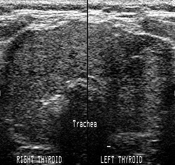
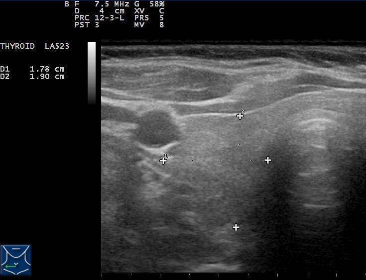
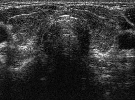
8 Compare echotexture of thyroid parenchyma to strap muscles and SCM.

9 Optimal Time Gain Compensation
 Lateral (transverse) Azimuthal (thickness of imaging")
10 Resolution Resolution is the ability to discriminate two structures as separate entities Types of resolution : Axial (distance from the transducer) Lateral (transverse) Azimuthal (thickness of imaging plane)
 LATERAL (side")
11 Resolution AZIMUTHAL (up-down) AXIAL (distance from transducer) LATERAL (side to side)
12 Resolution Ability to discriminate two adjacent objects as separate entities. The narrower the beam, the better the lateral resolution. The higher the frequency the better the axial resolution. Poor focus Image Good focus

13 Focus and Resolution Focused beam width determines Lateral and Azimuthal Resolution Near field (Fresnel Zone) Large variations of intensity Far field (Fraunhofer Zone) Greater variation with greater distance. Focal Zone - Area of maximal narrowing Pulse duration (frequency) determines Axial Resolution (axial resolution = 1/2 spatial pulse length) Practical Consideration - As frequency increases, axial resolution improves, but depth of imaging decreases. The number and depth of the focal zones are often adjustable and indicated on the display


14 Adjustment of number and position of focal zones


15 Adjustment of number and position of focal zones
16 Single focal zone
17 Four focal zones


18 Frequency and Resolution Higher frequency gives better resolution. Higher frequency gives less penetration. Need to find best compromise for depth of interest
 that allows")
 for deep")
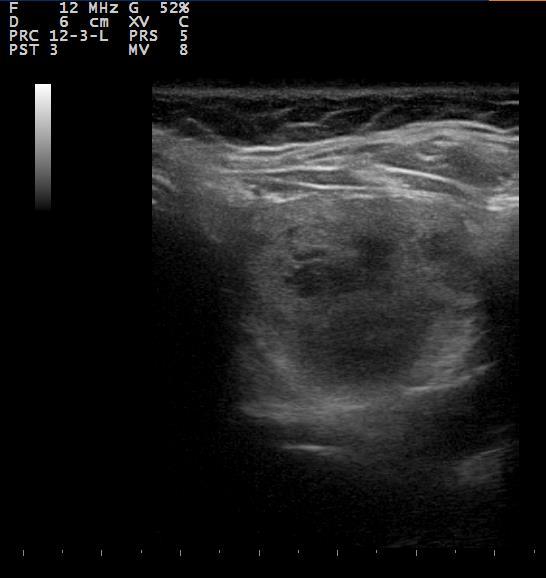
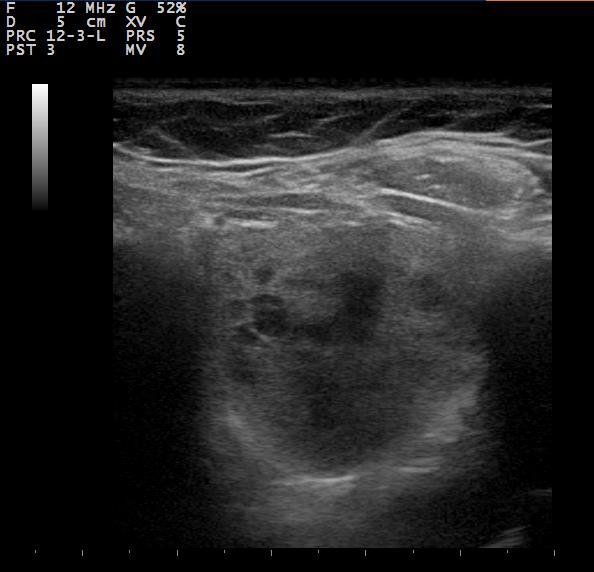
19 Image Optimization - Frequency Choose highest frequency (12-15 MHz) that allows adequate depth penetration. Lower frequencies (7-10 MHz) for deep structures or very obese subjects

20 Frequency and depth
21 Which of the following is true regarding ultrasound frequency? 1. Increasing frequency will increase depth of penetration. 2. Increasing frequency will improve resolution. 3. Increasing frequency will increase noise. 4. Both 1 and 2 are correct.
22 Advances in Technology Signal Processing Image Enhancement Noise reduction Edge sharpening Utilization of CT and MRI reconstruction algorithms Beam Steering Spatial compounding

23 Image Optimization- Compounding

24 Signal Processing Compunding
25 Comparison of standard and processed images


26 Effect of Compound Imaging on Artifacts Comet Tails

27 Effect of Compound imaging on Artifacts Edge Artifact and Enhancement


28 Effect of Compound Imaging on Spongiform Nodule

29 Image Optimization Dynamic range May increase conspicuity of subtle lesions

30 Doppler Shift
31 Color and Power Doppler Meritt, 1998

32 Color and Power Doppler Meritt, 1998
33 Color and Power Doppler Color Doppler Provides information regarding direction and velocity. More useful in vascular studies Power Doppler No information regarding velocity Less angle dependence Less noise Increased sensitivity for detection of flow


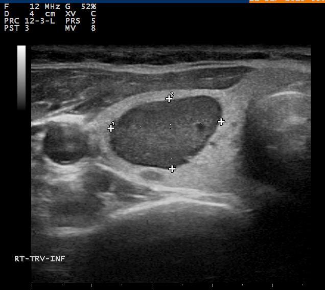
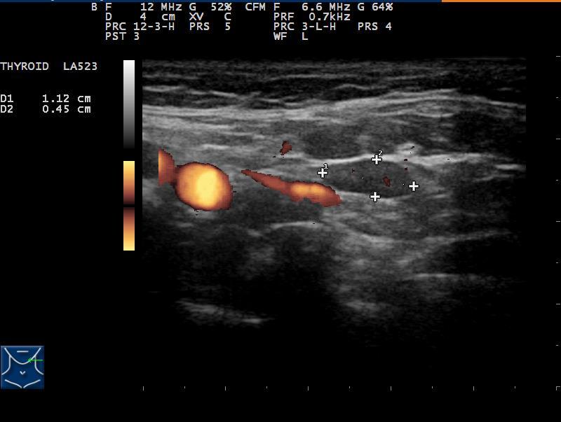
34 Doppler Lymph nodes In normal nodes vessels enter centrally at the hilus, and spread along the long axis. In malignant nodes aberrant vessels enter peripherally in the node capsule. Increased (disordered) vascularity may be seen peripherally and centrally.
35 Doppler of Nodes Demonstration of Chaotic or peripheral vascularity in malignant nodes Can be seen in reactive nodes Normal vascularity is reassuring Power Doppler for high sensitivity Use low wall filter Use a low PRF < 800 Low wall filter and low PRF both increase the sensitivity for detection of low flow.


36 Achieving the highest sensitivity with Doppler imaging. High Doppler sensitivity needed for lymph nodes. Power Doppler Maximum Doppler gain without noise. Low Pulse Repetition Frequency PRF < 800 Low wall filter.

37 PRF
38 PRF 700 Wall filter varies
39
40 Image Optimization Summary and Conclusions High quality equipment is preferable, BUT a great ultrasonographer using low quality equipment will obtain better images than a lousy ultrasonographer with great equipment. I need to find out what type of piano Mozart played so I can sound like him. User adjustments of gain, depth, frequency, focal zones, dynamic range, spatial compounding, pulse repetition frequency, and wall filter will give the optimal image quality.
Principles of Ultrasound Imaging Image Optimization
 Principles of Ultrasound Imaging Image Optimization Robert A. Levine, MD, FACE, ECNU Thyroid Center of New Hampshire Geisel School of Medicine at Dartmouth College Disclosures: No relevant financial or
The Physics of Echo. The Physics of Echo. The Physics of Echo Is there pericardial calcification? 9/30/13
 Basic Ultrasound Physics Kirk Spencer MD Speaker has no disclosures to make Sound Audible range 20Khz Medical ultrasound Megahertz range Advantages of imaging with ultrasound Directed as a beam Tomographic
Ultrasound Beamforming and Image Formation. Jeremy J. Dahl
 Ultrasound Beamforming and Image Formation Jeremy J. Dahl Overview Ultrasound Concepts Beamforming Image Formation Absorption and TGC Advanced Beamforming Techniques Synthetic Receive Aperture Parallel
Optimisation of Image Acquisition Bordeaux 16th November J.S. McGhie W.B. Vletter R. Frowijn No disclosures
 Optimisation of Image Acquisition Bordeaux 16th November 2016 J.S. McGhie W.B. Vletter R. Frowijn No disclosures Image optimisation: The Echo machine It looks difficult to drive an echo machine!! Some
12/26/2017. Alberto Ardon M.D.
 Alberto Ardon M.D. 1 Preparatory Work Ultrasound Physics http://www.nysora.com/mobile/regionalanesthesia/foundations-of-us-guided-nerve-blockstechniques/index.1.html Basic Ultrasound Handling https://www.youtube.com/watch?v=q2otukhrruc
Chapter 4. Pulse Echo Imaging. where: d = distance v = velocity t = time
 Chapter 4 Pulse Echo Imaging Ultrasound imaging systems are based on the principle of pulse echo imaging. These systems require the use of short pulses of ultrasound to create two-dimensional, sectional
The physics of ultrasound. Dr Graeme Taylor Guy s & St Thomas NHS Trust
 The physics of ultrasound Dr Graeme Taylor Guy s & St Thomas NHS Trust Physics & Instrumentation Modern ultrasound equipment is continually evolving This talk will cover the basics What will be covered?
Ultrasound Bioinstrumentation. Topic 2 (lecture 3) Beamforming
 Beamforming") Ultrasound Bioinstrumentation Topic 2 (lecture 3) Beamforming Angular Spectrum 2D Fourier transform of aperture Angular spectrum Propagation of Angular Spectrum Propagation as a Linear Spatial Filter Free
Ultrasound Bioinstrumentation Topic 2 (lecture 3) Beamforming Angular Spectrum 2D Fourier transform of aperture Angular spectrum Propagation of Angular Spectrum Propagation as a Linear Spatial Filter Free
Lesson 06: Pulse-echo Imaging and Display Modes. These lessons contain 26 slides plus 15 multiple-choice questions.
 Lesson 06: Pulse-echo Imaging and Display Modes These lessons contain 26 slides plus 15 multiple-choice questions. These lesson were derived from pages 26 through 32 in the textbook: ULTRASOUND IMAGING
Ultrasound Physics. History: Ultrasound 2/13/2019. Ultrasound
 Ultrasound Physics History: Ultrasound Ultrasound 1942: Dr. Karl Theodore Dussik transmission ultrasound investigation of the brain 1949-51: Holmes and Howry subject submerged in water tank to achieve
Artifacts. Artifacts. Causes. Imaging assumptions. Common terms used to describe US images. Common terms used to describe US images
 Artifacts Artifacts Chapter 20 What are they? Simply put they are an error in imaging These artifacts include reflections that are: not real incorrect shape, size or position incorrect brightness displayed
Ultrasound & Artifacts
 ISSN 2005-7881 Journal of Neurosonology 3(Suppl. 2):1-17, 2011 Ultrasound & Artifacts Siryung Han The Catholic University of Korea Artifacts False image- echoes without anatomic correlate US image dose
Photomultiplier Tube
 Nuclear Medicine Uses a device known as a Gamma Camera. Also known as a Scintillation or Anger Camera. Detects the release of gamma rays from Radionuclide. The radionuclide can be injected, inhaled or
3. Ultrasound Imaging(2)
") 3. Ultrasound Imaging(2) Lecture 13, 14 Medical Imaging Systems Jae Gwan Kim, Ph.D. jaekim@gist.ac.kr, X 2220 Department of BioMedical Science and Engineering Gwangju Institute of Sciences and Technology
3. Ultrasound Imaging(2) Lecture 13, 14 Medical Imaging Systems Jae Gwan Kim, Ph.D. jaekim@gist.ac.kr, X 2220 Department of BioMedical Science and Engineering Gwangju Institute of Sciences and Technology
Architecture of Quality Imaging Mary K. Henne, MS, CNMT, RDMS, RVT Ultrasound Education Specialist GE Healthcare
 Architecture of Quality Imaging Mary K. Henne, MS, CNMT, RDMS, RVT Ultrasound Education Specialist GE Healthcare 2 DOC1292532 Architecture of Quality Imaging Agile Acoustic Architecture E-Series and XDclear
Physics of Ultrasound Ultrasound Imaging and Artifacts รศ.นพ.เดโช จ กราพาน ชก ล สาขาหท ยว ทยา, ภาคว ชาอาย รศาสตร คณะแพทยศาสตร ศ ร ราชพยาบาล
 Physics of Ultrasound Ultrasound Imaging and Artifacts รศ.นพ.เดโช จ กราพาน ชก ล สาขาหท ยว ทยา, ภาคว ชาอาย รศาสตร คณะแพทยศาสตร ศ ร ราชพยาบาล Diagnosis TTE TEE ICE 3D 4D Evaluation of Cardiac Anatomy Hemodynamic
Ultrasound Imaging Ultr Michael Dadd 2007
 Ultrasound Imaging Ultrasound Physics & Instrumentation - Recommended Reading 1. Diagnostic Ultrasound: Principles and Instruments (7th Ed) Frederick W Kremkau W B Saunders Company 2. Applied Physics &
Design Your Performance
 MEDISON has been a leading name in diagnostic ultrasound since its foundation in 1985. As one of the only companies dedicated solely to ultrasound imaging, we have remained at the forefront of research
Doppler in Obstetrics: book by K Nicolaides, G Rizzo, K Hecher. Chapter on Doppler ultrasound: principles and practice by Colin Deane
 Doppler in Obstetrics: book by K Nicolaides, G Rizzo, K Hecher Chapter on Doppler ultrasound: principles and practice by Colin Deane INTRODUCTION Competent use of Doppler ultrasound techniques requires
Lesson 06: Pulse-echo Imaging and Display Modes. This lesson contains 22 slides plus 15 multiple-choice questions.
 Lesson 06: Pulse-echo Imaging and Display Modes This lesson contains 22 slides plus 15 multiple-choice questions. Accompanying text for the slides in this lesson can be found on pages 26 through 32 in
Medical Imaging (EL582/BE620/GA4426)
") Medical Imaging (EL582/BE620/GA4426) Jonathan Mamou, PhD Riverside Research Lizzi Center for Biomedical Engineering New York, NY jmamou@riversideresearch.org On behalf of Prof. Daniel Turnbull Outline
Medical Imaging (EL582/BE620/GA4426) Jonathan Mamou, PhD Riverside Research Lizzi Center for Biomedical Engineering New York, NY jmamou@riversideresearch.org On behalf of Prof. Daniel Turnbull Outline
Image Optimization: The Sonographer s Responsibility. Prepared by Cathy Daniels, EdD, RTR, RDMS, RDCS, RVT
 Image Optimization: The Sonographer s Responsibility Prepared by Cathy Daniels, EdD, RTR, RDMS, RDCS, RVT Image Optimization: The Sonographer s Responsibility Cathy Daniels, EdD, RTR, RDMS, RDCS, RVT Disclosure
Introduction to Ultrasound Physics
 Introduction to Ultrasound Physics Vassilis Sboros Medical Physics and Cardiovascular Sciences University of Edinburgh Transverse waves Water remains in position Disturbance traverse producing more wave
Nuove tecnologie per ecografia ad ultrasuoni: da 2D a 4D
 DINFO Dipartimento di Ingegneria dell Informazione Department of Information Engineering Nuove tecnologie per ecografia ad ultrasuoni: da 2D a 4D Piero Tortoli Microelectronics Systems Design Lab 1 Introduction
Beyond Performance and Value
 Putting the back in ultrasound Beyond Performance and Value Esaote s new ultra-performance MyLab 9 exp ultrasound system is designed to support a full range of shared service diagnostic imaging environments.
Introduction to Medical Engineering (Medical Imaging) Ultrasound Imaging. Ho Kyung Kim Pusan National University
 Ultrasound Imaging. Ho Kyung Kim Pusan National University") Introduction to Medical Engineering (Medical Imaging) Suetens 6 Ultrasound Imaging Ho Kyung Kim Pusan National University Sound Sonic: 20 Hz 20 khz (audible frequency) Subsonic () Ultrasound
Introduction to Medical Engineering (Medical Imaging) Suetens 6 Ultrasound Imaging Ho Kyung Kim Pusan National University Sound Sonic: 20 Hz 20 khz (audible frequency) Subsonic () Ultrasound
A COMPACT SYSTEM WITH ADVANCED PERFORMANCE
 Samsung Medison is a global leading medical devices company. Founded in 1985, the company sells cutting-edge diagnostic ultrasound devices around the world in various medical fields. The company has attracted
Optical coherence tomography
 Optical coherence tomography Peter E. Andersen Optics and Plasma Research Department Risø National Laboratory E-mail peter.andersen@risoe.dk Outline Part I: Introduction to optical coherence tomography
ACOUSTIC MICRO IMAGING ANALYSIS METHODS FOR 3D PACKAGES
 ACOUSTIC MICRO IMAGING ANALYSIS METHODS FOR 3D PACKAGES Janet E. Semmens Sonoscan, Inc. Elk Grove Village, IL, USA Jsemmens@sonoscan.com ABSTRACT Earlier studies concerning evaluation of stacked die packages
FREQUENTLY ASKED QUESTIONS
 FREQUENTLY ASKED S Q9: Expanding aperture is a technique in ultrasound beamforming where the objects very close to the aperture are imaged by a lower number of aperture elements. That is, as the depth
Lesson 02: Sound Wave Production. This lesson contains 24 slides plus 11 multiple-choice questions.
 Lesson 02: Sound Wave Production This lesson contains 24 slides plus 11 multiple-choice questions. Accompanying text for the slides in this lesson can be found on pages 2 through 7 in the textbook: ULTRASOUND
The Script of ZST + Presentation. MIS Upstream Marketing Team [ 日期 ]
![The Script of ZST + Presentation. MIS Upstream Marketing Team [ 日期 ]](/thumbs/94/119182132.jpg "The Script of ZST + Presentation. MIS Upstream Marketing Team [ 日期 ]") 1 The Script of ZST + Presentation MIS Upstream Marketing Team [ 日期 ] 1 The Script of ZST + Presentation Since Mindray was founded to develop ultrasound business, core technology has always been the engine
1 The Script of ZST + Presentation MIS Upstream Marketing Team [ 日期 ] 1 The Script of ZST + Presentation Since Mindray was founded to develop ultrasound business, core technology has always been the engine
4 Working With Scan Modes
 4 Working With Scan Modes Scan Modes Overview All of the information in this chapter pertains to live imaging. Many of the controls and functions change when you freeze the scan. For information on using
Session: 2A NEW ULTRASOUND SYSTEMS Chair: H. Ermert University of Bochum 2A-1 10:30 a.m.
 Session: 2A NEW ULTRASOUND SYSTEMS Chair: H. Ermert University of Bochum 2A-1 10:30 a.m. TISSUE HARMONIC IMAGING WITH IMPROVED TEMPORAL RESOLUTION D. J. NAPOLITANO*, C. H. CHOU, G. W. MCLAUGHLIN, T. L.
Quick Reference Guide
 siemens.com/nx3 Quick Reference Guide ACUSON NX3 Series Contents 2 System Overview 3 Getting Started 8 2D Mode and M-mode 12 Color and Spectral Doppler 24 Measurements and Calculations 38 Text, Arrows
Physics of ultrasound
 1 Physics of ultrasound Basic principles Nature of ultrasound Sound = longitudinal, mechanical wave particles move parallel to direction of travel Audible sound < 20 khz Ultrasound > 20 khz Sound cannot
Physics of Ultrasound & Doppler. Sang Jae Rhee. MD., PhD. Division of Cardiovascular Medicine Wonkwang University Hospital
 Physics of Ultrasound & Doppler Sang Jae Rhee. MD., PhD. Division of Cardiovascular Medicine Wonkwang University Hospital Classification of Sound Infrasound Audible sound Ultrasound < 20 Hz 20-20,000 Hz
Doppler Ultrasound. Amanda Watson.
 Doppler Ultrasound Amanda Watson amanda.watson1@nhs.net Before we start Why does blood appear black on a B-mode image? B-mode echoes vs. Doppler echoes In B-Mode we are concerned with the position and
Virtual ultrasound sources
 CHAPTER SEVEN Virtual ultrasound sources One of the drawbacks of the generic synthetic aperture, the synthetic transmit aperture, and recursive ultrasound imaging is the low signal-to-noise ratio (SNR)
Fig. 1
 PhysicsAndMathsTutor.com 1 1. Fig. 1 shows data for the intensity of a parallel beam of X-rays after penetration through varying thicknesses of a material. intensity / MW m 2 thickness / mm 0.91 0.40 0.69
18th World Conference on Nondestructive Testing, April 2012, Durban, South Africa. Joanna X.Qiao 1, Matthias Jobst 2
 8th World Conference on ondestructive Testing, 6-0 April 0, Durban, outh Africa An Adaptive Phased-Array Imaging ethod for Ultrasonic Testing Joanna X.Qiao, atthias Jobst GE Inspection Technologies; 50
Digital Imaging CT & MR
 Digital Imaging CT & MR January 22, 2008 Digital Radiography, CT and MRI generate images in a digital format What is a Digital Image? A digital image is made up of picture elements, pixels row by column
Confocal Imaging Through Scattering Media with a Volume Holographic Filter
 Confocal Imaging Through Scattering Media with a Volume Holographic Filter Michal Balberg +, George Barbastathis*, Sergio Fantini % and David J. Brady University of Illinois at Urbana-Champaign, Urbana,
Introduction. Parametric Imaging. The Ultrasound Research Interface: A New Tool for Biomedical Investigations
 The Ultrasound Research Interface: A New Tool for Biomedical Investigations Shelby Brunke, Laurent Pelissier, Kris Dickie, Jim Zagzebski, Tim Hall, Thaddeus Wilson Siemens Medical Systems, Issaquah WA
Easy Ultrasonic Phased Array Inspection of Corrosion - Resistant Alloys and Dissimilar Weld Materials
 Multimedia Application Notes Easy Ultrasonic Phased Array Inspection of Corrosion - Resistant Alloys and Dissimilar Weld Materials Many industries increasingly use austenitic welds and welds containing
Point Spread Function. Confocal Laser Scanning Microscopy. Confocal Aperture. Optical aberrations. Alternative Scanning Microscopy
 Bi177 Lecture 5 Adding the Third Dimension Wide-field Imaging Point Spread Function Deconvolution Confocal Laser Scanning Microscopy Confocal Aperture Optical aberrations Alternative Scanning Microscopy
CHAPTER 1 INTRODUCTION
 CHAPTER 1 INTRODUCTION Spatial resolution in ultrasonic imaging is one of many parameters that impact image quality. Therefore, mechanisms to improve system spatial resolution could result in improved
Introduction. Chapter 16 Diagnostic Radiology. Primary radiological image. Primary radiological image
 Introduction Chapter 16 Diagnostic Radiology Radiation Dosimetry I Text: H.E Johns and J.R. Cunningham, The physics of radiology, 4 th ed. http://www.utoledo.edu/med/depts/radther In diagnostic radiology
Printed in Japan E318
 Diagnostic Ultrasound System MODEL PROSOUND 6 The specifications, shape and color of this product are subject to change without notice. The standard components and optional items vary depending on the
Ultrasound physical principles in today s technology
 Education Ultrasound physical principles in today s technology Brian Starkoff M.App.Sc.(Med. Ultrasound), AMS Holland Park Brisbane Queensland Australia Correspondence to email starkoff@optusnet.com.au
 www.hitachi-aloka.com Revolutionary Performance; Ease of Use The ProSound 6 is the next generation of compact color ultrasound systems, providing unprecedented performance with a broad range of applications.
UNIVERSITY OF NAIROBI COLLEGE OF EDUCATION AND EXTERNAL STUDIES
 UNIVERSITY OF NAIROBI COLLEGE OF EDUCATION AND EXTERNAL STUDIES COURSE TITLE: BED (SCIENCE) UNIT TITLE: WAVES AND OPTICS UNIT CODE: SPH 103 UNIT AUTHOR: PROF. R.O. GENGA DEPARTMENT OF PHYSICS UNIVERSITY
SONOGRAPHIC PHYSICS, INSTRUMENTATION & DOPPLER REVIEW Part 3
 SONOGRAPHIC PHYSICS, INSTRUMENTATION & DOPPLER REVIEW 2012 Part 3 1 Doppler Imaging 2 DOPPLER TRANSDUCER SAME FREQUENCY During Doppler operation, the reflected sound has the same frequency as the transmitted
Excellent Performance; Ease of Use
 Excellent Performance; Ease of Use High performance with a broad range of applications - the compact ProSound α6 is at your service. Our ProSound series has a well-established reputation in hospitals and
(A) 2f (B) 2 f (C) f ( D) 2 (E) 2
 2f (B) 2 f (C) f ( D) 2 (E) 2") 1. A small vibrating object S moves across the surface of a ripple tank producing the wave fronts shown above. The wave fronts move with speed v. The object is traveling in what direction and with what
1. A small vibrating object S moves across the surface of a ripple tank producing the wave fronts shown above. The wave fronts move with speed v. The object is traveling in what direction and with what
SIMULATION OF B-SCAN IMAGES FROM TWO-DIMENSIONAL TRANSDUCER ARRAYS: PART II - COMPARISONS BETWEEN LINEAR AND TWO-DIMENSIONALPHASED ARRAYS
 ULTRASONIC IMAGING 14, 344-353 (1992) SIMULATION OF B-SCAN IMAGES FROM TWO-DIMENSIONAL TRANSDUCER ARRAYS: PART II - COMPARISONS BETWEEN LINEAR AND TWO-DIMENSIONALPHASED ARRAYS Daniel H. Turnbull and F.
Q5 VET. Compact, Affordable Color Doppler for VET
 Q5 VET Compact, Affordable Color Doppler for VET Key Benefits Ergonomic design for learning easily, using efficiently Professional probes and software for veterinary Abundant image mode: B, 2B,4B,C,PW,M
COMPUTER PHANTOMS FOR SIMULATING ULTRASOUND B-MODE AND CFM IMAGES
 Paper presented at the 23rd Acoustical Imaging Symposium, Boston, Massachusetts, USA, April 13-16, 1997: COMPUTER PHANTOMS FOR SIMULATING ULTRASOUND B-MODE AND CFM IMAGES Jørgen Arendt Jensen and Peter
Ihor TROTS, Andrzej NOWICKI, Marcin LEWANDOWSKI
 ARCHIVES OF ACOUSTICS 33, 4, 573 580 (2008) LABORATORY SETUP FOR SYNTHETIC APERTURE ULTRASOUND IMAGING Ihor TROTS, Andrzej NOWICKI, Marcin LEWANDOWSKI Institute of Fundamental Technological Research Polish
Echo Artifacts: The Cause and Solution
 Echo Artifacts: The Cause and Solution David Adams, RCS, RDCS, FASE Duke University Medical Center Disclosures None My Happy / Sad ratio 20% Sad 1 st talk on Sunday (post party) Talk about Artifacts Artifacts
Multi-Element Synthetic Transmit Aperture Method in Medical Ultrasound Imaging Ihor Trots, Yuriy Tasinkevych, Andrzej Nowicki and Marcin Lewandowski
 Multi-Element Synthetic Transmit Aperture Method in Medical Ultrasound Imaging Ihor Trots, Yuriy Tasinkevych, Andrzej Nowicki and Marcin Lewandowski Abstract The paper presents the multi-element synthetic
Retrospective Transmit Beamformation. Whitepaper. ACUSON SC2000 Volume Imaging Ultrasound System. Answers for life.
 Whitepaper Retrospective Transmit Beamformation ACUSON SC2000 Volume Imaging Ultrasound System Chuck Bradley, Ph.D. Siemens Healthcare Sector Ultrasound Business Unit Mountain View, California USA Answers
UGEO H60. Performance in Style. Features
 UGEO H60 Performance in Style The UGEO H60 implements superior performance with new design principles of simplicity and lightness. Its 10.1" touchscreen improves usability while its 18.5" LED monitor enhances
M5 Diagnostic Ultrasound System
 V0807 M5 Diagnostic Ultrasound System Mindray s ultrasound family is now introducing a new member, M5 hand-carried color Doppler system. M5, coming in a laptop size with comprehensive ergonomic design,
A Modified Synthetic Aperture Focussing Technique Utilising the Spatial Impulse Response of the Ultrasound Transducer
 A Modified Synthetic Aperture Focussing Technique Utilising the Spatial Impulse Response of the Ultrasound Transducer Stephen A. MOSEY 1, Peter C. CHARLTON 1, Ian WELLS 1 1 Faculty of Applied Design and
DC-6. Diagnostic Ultrasound System
 DC-6 Diagnostic Ultrasound System DC-6 is a general purpose color Doppler ultrasound system aiming at most clinical areas both in exam and research with various transducers and multi software packages
Ques on (2): [18 Marks] a) Draw the atrial synchronous Pacemaker block diagram and explain its operation. Benha University June 2013
![Ques on (2): [18 Marks] a) Draw the atrial synchronous Pacemaker block diagram and explain its operation. Benha University June 2013](/thumbs/87/96832478.jpg "Ques on (2): [18 Marks] a) Draw the atrial synchronous Pacemaker block diagram and explain its operation. Benha University June 2013") Benha University June 2013 Benha Faculty of Engineering Electrical Department Hospital Instrumentations (E472) 4 Th year (control) Dr.Waleed Abdel Aziz Salem Time: 3 Hrs Answer the following questions.
Benha University June 2013 Benha Faculty of Engineering Electrical Department Hospital Instrumentations (E472) 4 Th year (control) Dr.Waleed Abdel Aziz Salem Time: 3 Hrs Answer the following questions.
MICROWAVE DIATHERMY AND SURGICAL DIATHERMY DIATHERMICS
 MICROWAVE DIATHERMY AND SURGICAL DIATHERMY 1 Microwave diathermy Microwave diathermy uses microwaves to generate heat in the body. It can be used to evenly warm deep tissues without heating the skin. Microwave
Spectral Distance Amplitude Control for Ultrasonic Inspection of Composite Components
 ECNDT 26 - Mo.2.6.4 Spectral Distance Amplitude Control for Ultrasonic Inspection of Composite Components Uwe PFEIFFER, Wolfgang HILLGER, DLR German Aerospace Center, Braunschweig, Germany Abstract. Ultrasonic
Better Imaging with a Schmidt-Czerny-Turner Spectrograph
 Better Imaging with a Schmidt-Czerny-Turner Spectrograph Abstract For years, images have been measured using Czerny-Turner (CT) design dispersive spectrographs. Optical aberrations inherent in the CT design
Endoscopic Ultrasonography System
 Endoscopic Ultrasonic Processor SU- -H-, SU- -S- Power rating Power supply rating Current consumption(rated) Dimensions Size Weight Ultrasonography Probe types image display Scanning modes Special modes*
A Breakthrough in Sputtering Target Inspections: Ultra-High Speed Phased Array Scanning with Volume Focusing
 17th World Conference on Nondestructive Testing, 25-28 Oct 2008, Shanghai, China A Breakthrough in Sputtering Target Inspections: Ultra-High Speed Phased Array Scanning with Volume Focusing Dominique Braconnier,
HISTORY. CT Physics with an Emphasis on Application in Thoracic and Cardiac Imaging SUNDAY. Shawn D. Teague, MD
 CT Physics with an Emphasis on Application in Thoracic and Cardiac Imaging Shawn D. Teague, MD DISCLOSURES 3DR- advisory committee CT PHYSICS WITH AN EMPHASIS ON APPLICATION IN THORACIC AND CARDIAC IMAGING
Answer: TGC is needed to amplify echoes from deeper structures so that they appear as bright as similar structures located at more shallow depths.
 Q47. When performing a sonogram why the sonographer needs to use the TGC? TGC is needed to amplify echoes from deeper structures so that they appear as bright as similar structures located at more shallow
SECTION 2 BROADBAND RF CHARACTERISTICS. 2.1 Frequency bands
 SECTION 2 BROADBAND RF CHARACTERISTICS 2.1 Frequency bands 2.1.1 Use of AMS(R)S bands Note.- Categories of messages, and their relative priorities within the aeronautical mobile (R) service, are given
CryoSat footprints. Aresys Technical Note. ESA Document REF. Issue 1.1 Date 6 March 2013 Pages 8. Michele Scagliola ARESYS S.r.l
 CryoSat footprints Aresys Technical Note ESA Document REF XCRY-GSEG-EOPG-TN-13-0013 Aresys Internal REF SAR-CRY2-TEN-6331 Issue 1.1 Date 6 March 2013 Pages 8 Author Michele Scagliola ARESYS S.r.l Signature
Tomosynthesis and Motion
 Tomosynthesis (3D) Motion Unsharpness Occurs at about the same frequency as conventional mammography (2D) Presents the same issues as 2D motion, EXCEPT that motion may go undetected Most common patient-related
Multimodal simultaneous photoacoustic tomography, optical resolution microscopy and OCT system
 Multimodal simultaneous photoacoustic tomography, optical resolution microscopy and OCT system Edward Z. Zhang +, Jan Laufer +, Boris Považay *, Aneesh Alex *, Bernd Hofer *, Wolfgang Drexler *, Paul Beard
Lesson 12: Doppler Principles. This lesson contains 50 slides plus 26 multiple-choice questions.
 Lesson 12: Doppler Principles This lesson contains 50 slides plus 26 multiple-choice questions. Accompanying text for the slides in this lesson can be found on pages 59 through 80 in the textbook: DOPPLER
Diagnostic Ultrasound System. Operation Note
 M5 Diagnostic Ultrasound System Table of Contents System Introduction...3 Control Panel...4 Control Panel...5 Control Panel...6 Control Panel...7 Control Panel...8 Control Panel...9 Power ON / OFF the
Parameter Estimation Techniques for Ultrasound Phase Reconstruction. Fatemeh Vakhshiteh Sept. 16, 2010
 Parameter Estimation Techniques for Ultrasound Phase Reconstruction Fatemeh Vakhshiteh Sept. 16, 2010 Presentation Outline Motivation Thesis Objectives Background Simulation Quadrature Phase Measurement
Lecture 08. Fundamentals of Lidar Remote Sensing (6)
") Lecture 08. Fundamentals of Lidar Remote Sensing (6) Basic Lidar Architecture Basic Lidar Architecture Configurations vs. Arrangements Transceiver with HOE A real example: STAR Na Doppler Lidar Another
Lecture 08. Fundamentals of Lidar Remote Sensing (6) Basic Lidar Architecture Basic Lidar Architecture Configurations vs. Arrangements Transceiver with HOE A real example: STAR Na Doppler Lidar Another
monitoring device ought to find wide clinical application. available, while section three describes the Doppler interface with the B-scan machine.
 THE YALE JOURNAL OF BIOLOGY AND MEDICINE 50 (1977), 367-373 Pulse-Doppler Ultrasound and Its Clinical Application PETER ATKINSON AND PETER N.T. WELLS Yale University School of Medicine, New Haven, Connecticut
Physics 3340 Spring Fourier Optics
 Physics 3340 Spring 011 Purpose Fourier Optics In this experiment we will show how the Fraunhofer diffraction pattern or spatial Fourier transform of an object can be observed within an optical system.
Standard Guide for Evaluating Performance Characteristics of Phased-Array Ultrasonic Testing Instruments and Systems 1
 Designation: E2491 08 Standard Guide for Evaluating Performance Characteristics of Phased-Array Ultrasonic Testing Instruments and Systems 1 This standard is issued under the fixed designation E2491; the
ENDOSCOPIC ULTRASOUND SYSTEMS
 ENDOSCOPIC ULTRASOUND SYSTEMS DISCOVER HIGH-PRECISION DIAGNOSES AND PROCEDURES NEW ENDOSCOPIC ULTRASOUND Ultrasonography revolutionized the clinical approach to patients with digestive and respiratory
LMT F14. Cut in Three Dimensions. The Rowiak Laser Microtome: 3-D Cutting and Imaging
 LMT F14 Cut in Three Dimensions The Rowiak Laser Microtome: 3-D Cutting and Imaging The Next Generation of Microtomes LMT F14 - Non-contact laser microtomy The Rowiak laser microtome LMT F14 is a multi-purpose
Explain what is meant by a photon and state one of its main properties [2]
![Explain what is meant by a photon and state one of its main properties [2]](/thumbs/80/82516318.jpg "Explain what is meant by a photon and state one of its main properties [2]") 1 (a) A patient has an X-ray scan taken in hospital. The high-energy X-ray photons interact with the atoms inside the body of the patient. Explain what is meant by a photon and state one of its main properties....
1 (a) A patient has an X-ray scan taken in hospital. The high-energy X-ray photons interact with the atoms inside the body of the patient. Explain what is meant by a photon and state one of its main properties....
A COST-EFFECTIVE METHOD FOR ULTRASOUND VOLUMETRIC IMAGING
 Mathematical & Computational Applications, Voll, No. 2,pp 127-132, 1996 Association for Scientific ReseardJ. A COST-EFFECTIVE METHOD FOR ULTRASOUND VOLUMETRIC IMAGING F. Nazan Urar * and Mustafa Karaman
Sonic Distance Sensors
 Sonic Distance Sensors Introduction - Sound is transmitted through the propagation of pressure in the air. - The speed of sound in the air is normally 331m/sec at 0 o C. - Two of the important characteristics
Ultrasonic Linear Array Medical Imaging System
 Ultrasonic Linear Array Medical Imaging System R. K. Saha, S. Karmakar, S. Saha, M. Roy, S. Sarkar and S.K. Sen Microelectronics Division, Saha Institute of Nuclear Physics, 1/AF Bidhannagar, Kolkata-700064.
OPERATING MANUAL MINIDOP ES-100VX POCKET DOPPLER
 OPERATING MANUAL MINIDOP ES-100VX POCKET DOPPLER CONTENTS * Features.......................... 1 * Cautions.......................... 2 * Clinical applications................. 4 * Operating controls..................
MULTI-FREQUENCY ULTRASOUND IMAGING: PHANTOM STUDY
 MULTI-FREQUENCY ULTRASOUND IMAGING: PHANTOM STUDY SITI NUR MASTURAH BINTI ABDUL MALEK DEPARTMENT OF DIAGNOSTIC IMAGING AND RADIOTHERAPY, KULLIYYAH OF ALLIED HEALTH SCIENCES, INTERNATIONAL ISLAMIC UNIVERSITY
BEAM DISTORTION IN DOPPLER ULTRASOUND FLOW TEST RIGS: MEASUREMENT USING A STRING PHANTOM
 BEAM DISTORTION IN DOPPLER ULTRASOUND FLOW TEST RIGS: MEASUREMENT USING A STRING PHANTOM R. Steel, P. J. Fish School of Informatics, University of Wales, Bangor, UK Abstract-The tube in flow rigs used
Journal of Digital Imaging
 Journal of Digital Imaging VOL 5, NO 1 FEBRUARY 1992 Computers in Ultrasonic Imaging Timothy J. Hall, Stanton J. Rosenthal, Michael F. Insana, and Arch W. Templeton This article describes the role of computers
Exercise 2: Simulation of ultrasound field using Field II
 Exercise 2: Simulation of ultrasound field using Field II The purposes of this exercise is to learn how to: Set up the simulation environment and model a transducer in Field II o Single element transducer
A new Sensor for the detection of low-flying small targets and small boats in a cluttered environment
 UNCLASSIFIED /UNLIMITED Mr. Joachim Flacke and Mr. Ryszard Bil EADS Defence & Security Defence Electronics Naval Radar Systems (OPES25) Woerthstr 85 89077 Ulm Germany joachim.flacke@eads.com / ryszard.bil@eads.com
Pulse Sequence Design and Image Procedures
 Pulse Sequence Design and Image Procedures 1 Gregory L. Wheeler, BSRT(R)(MR) MRI Consultant 2 A pulse sequence is a timing diagram designed with a series of RF pulses, gradients switching, and signal readout
INSPECTION OF THERMAL BARRIERS OF PRIMARY PUMPS WITH PHASED ARRAY PROBE AND PIEZOCOMPOSITE TECHNOLOGY
 INSPECTION OF THERMAL BARRIERS OF PRIMARY PUMPS WITH PHASED ARRAY PROBE AND PIEZOCOMPOSITE TECHNOLOGY J. Poguet Imasonic S.A. France E. Abittan EDF-GDL France Abstract In order to meet the requirements