Optimisation of Image Acquisition Bordeaux 16th November J.S. McGhie W.B. Vletter R. Frowijn No disclosures
|
|
|
- Meryl Davis
- 5 years ago
- Views:
Transcription


1 Optimisation of Image Acquisition Bordeaux 16th November 2016 J.S. McGhie W.B. Vletter R. Frowijn No disclosures


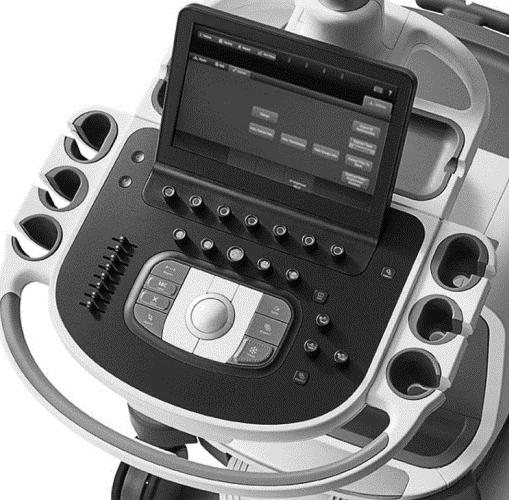
2 Image optimisation: The Echo machine It looks difficult to drive an echo machine!!

3 Some things never change they just look better Current machines control much of the image and signal processing
4 Image optimisation: Echocardiographic machine capable of: - 2D imaging, M-mode - pulsed & continuous wave Doppler - colour flow Doppler mapping - electrocardiogram - analysis software - optional: tissue doppler analysis, 3D echocardiography. Machine operator: - fully trained,dedicated,sonographer,physicians - continuing education credits
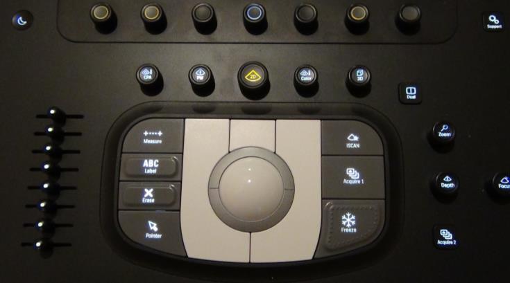
5 Image optimisation: Knobology Echo machine controls can be grouped according to application: - Imaging Controls - Spectral Doppler Controls - Colour Flow Mapping Controls - Display, Measurement and Recording - Set Up Differences exist in manufactures with respect to how much OPERATOR control is allowed.

6 Image optimisation: The Echo machine Monitor: Adjust the contrast and brightness so that both the weakest and strongest gray levels are present on the screen System preset: Standard for your lab to produce uniform appereance of studies. A MUST in colour Doppler maps ie33
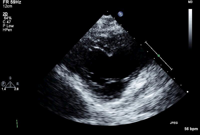
7 Image optimisation Gain iscan Depth Focus TGC
8 Image optimisation
9 Image optimisation: Technical skill Patient position - left (right) lateral decubitus position supine position Selection of the transducer Higher frequency: Better resolution less penetration (pediatric) Lower frequency: Poorer resolution better penetration (adult) Transducer position - Minor adjustment of transducer position can provide a better acoustic window. - Consider contact between transducer tip and skin Focus

10 Image optimisation: Selection of the transducer Fundamental S12-4 Best spatial resolution Most impaired penetration 2 nd Harm Mhz Impaired spatial resolution Most possible penetration The worse the acoustic window the lower the frequency
11 Image optimisation: Technical skill Patient position - left (right) lateral decubitus position supine position Selection of the transducer Higher frequency: Better resolution less penetration (pediatric) Lower frequency: Poorer resolution better penetration (adult) Transducer position - Consider contact between transducer tip and skin - Minor adjustment of transducer position can provide a better acoustic window. Focus
12 Image optimisation: Transducer position

13 Image optimisation: Transducer position

14 Image optimisation: Focus To optimize resolution at a specific distance Structures proximal to the focus level are better visualized
15 Image optimisation: Gain settings Gain setting Overall gain Adjusts the amplitude of the received signals over the total length of the ultrasound beam. Time-gain compensation Allows differential adjustments along this length to compensate for the effect of attenuation Compression The amplitude range of the reflected signal is compressed into a range of values from white to black

16 Image optimisation: Gain setting Correct gain setting Overall gain Time gain compensation (TGC)
17 Image optimisation: Compression Gainsetting Overall gain Adjusts the amplitude of the received signals over the total length of the ultrasound beam. Time-gain compensation Allows differential adjustments along this length to compensate for the effect of attenuation Compression The amplitude range of the reflected signal is compressed into a range of values from white to black


18 Image optimisation: Compression Compress 30 Gain 62% Compress 40 Gain 62% Compress 50 Gain 62% Compress 60 Gain 62% To provide an image with a gradation of gray levels the number of levels of gray can be adjusted by the compress / dynamic range setting Default setting (ie 33)
19 Image optimisation: Tissue Harmonic Imaging Tissue Harmonic Imaging In tissue harmonic imaging the harmonic frequency energy is generated as the ultrasonic wave propagates through the tissue By processing the received signals the second harmonic is filtered out and displayed Framerate Number of images per second depends on the number of scan lines and adjusted depth (routine setting 40 frames per second)
 Gain 62% Harmonic imaging improves signal-to-noise-ratio.")
20 Image optimisation: Fundamental 2 nd Harmonic Fundamental (FR 75Hz) Gain 44% 2 nd Harm Mhz (FR 64Hz) Gain 62% Harmonic imaging improves signal-to-noise-ratio. Better lateral resolution poorer axial resolution

21 Image optimisation: Fundamental 2 nd Harmonic Important The type of processing required to filter out the received harmonic signal does make structures within the heart appear slightly thicker in harmonic as compared with fundamental frequency

22 Image optimisation: 2 nd Harmonic - XRES
23 Image optimisation: Framerate Tissue Harmonic Imaging In tissue harmonic imaging the harmonic frequency energy is generated as the ultrasonic wave propagates through the tissue By processing the received signals the second harmonic is filtered out and displayed Framerate Number of images per second depends on the adjusted depth, sector angle and number of scan lines. (routine setting 40 frames per second)


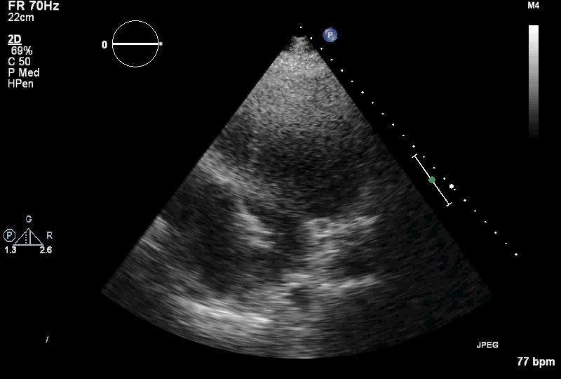
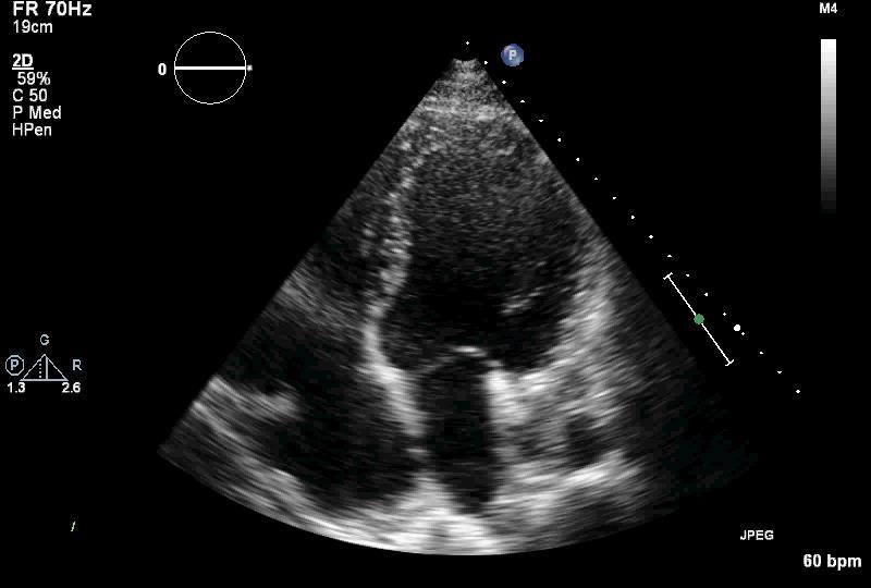
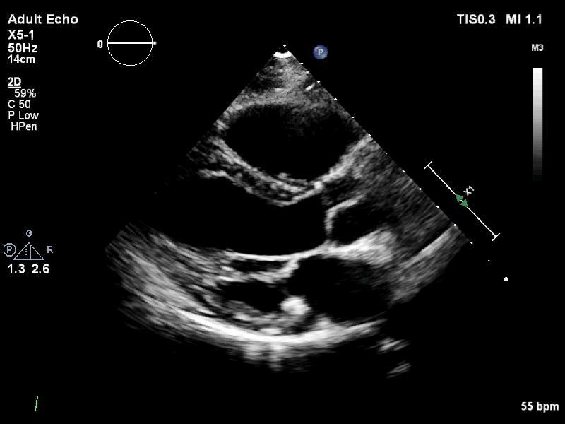
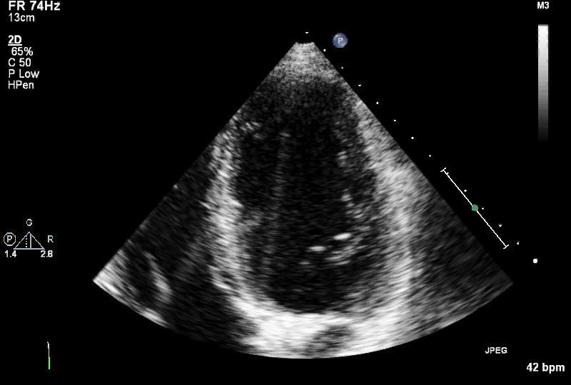
24 Image optimisation: Framerate Begin with sufficient depth to see beyond the heart Reduce depth till area of interest fills the screen Depth 19cm = FR 50Hz Depth 13cm = FR 55Hz
25 Image optimisation: Framerate Decrease sector angle Decrease line density Depth 13cm = FR 72Hz (speckle tracking) Depth 13cm = FR 88Hz


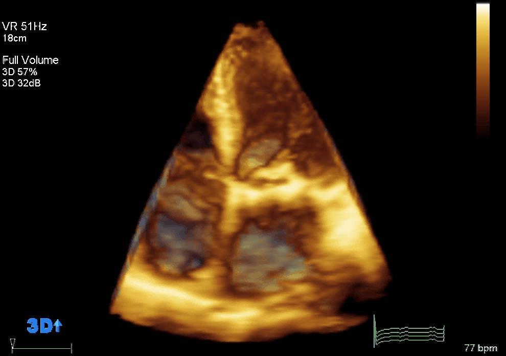
26 Image optimisation: Framerate X5-1 matrix transducer Matrix array technology utilizes 2400 fully-sampled elements for 360-degree focusing and steering xplane

")
27 Image optimisation: Framerate Frame rate 74Hz Frame rate 37Hz xplane lateral tilt +30 (+45 ) -30 (-45 )
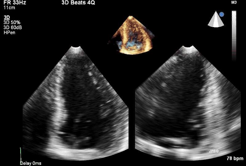
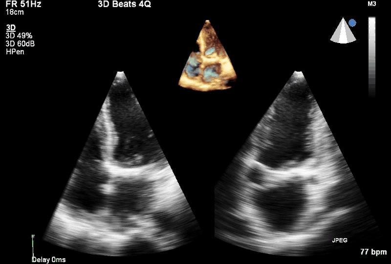
28 Image optimisation: Framerate ROI: LV (VR 33HZ) ROI: LA (VR 51HZ)
29 Color Doppler Flow Imaging Gain Setting Adjusts the degree of amplification of received Doppler signals To optimize the flowsignal the gain setting is just below the level of random background noise Framerate + Velocity range Sector depth Sector width Line density Pulse repetition frequency (PRF)


30 Color Doppler Flow Imaging: 2D gain Reduce 2D gain! Color flow data is not displayed on the top of structures (including noise due to excessive gain)

31 Color Doppler Flow Imaging: Color gain setting Radom noise Correct gain setting Too low gain = diminished sensitivity (large jets appear smaller)


32 Color Doppler Flow Imaging: FR sector size Frame rate 8 Hz Frame rate 21 Hz Increased sector width requires more scan lines resulting in slower frame rate So keep color area to a minimum


 -30")
33 Color Doppler Flow Imaging: FR sector size Frame rate 22Hz xplane lateral tilt Frame rate 11Hz +30 (+45 ) -30 (-45 )

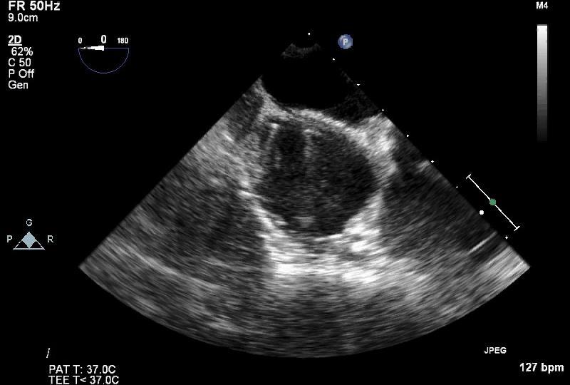
34 Color Doppler Flow Imaging: FR sector depth FR 17 Hz FR 17 Hz FR 29 Hz Same transmit-receiving time No difference in frame rates Less transmit-receiving time Higher frame rate


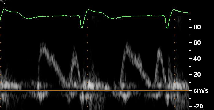
35 Color Doppler Flow Imaging: Velocity range VR 91 cm/s VR 61 cm/s VR 30 cm/s Default setting velocity scale 60 cm/s

36 Color Doppler Flow Imaging: Velocity range(tcpc) Low PRF setting use a low wall filter, therefore low velocity flow is visible
37 Spectral Doppler modes Continuous Wave (CW) No upper velocity limit but No depth discrimination Pulsed Wave (PW) Upper velocity limited by Aliasing but Does provide spatial location


38 Pulsed Wave Doppler: Sample volume position


39 Standard settings pulsed/ continuous wave Doppler Filter setting Baseline shift High pass filters eliminate low frequency Doppler shifts Use Baseline shift to maximise Velocity Scale Velocity range Gain setting Optimize for precise velocity measurements Too high gain setting overrate velocity measurements


40 Continuous Wave Doppler: Gain setting Vmax 3.2 m/s Max PG 41 mmhg Mean PG 24 mmhg VTI 83 cm Vmax 3.5 m/s Max PG 50 mmhg Mean PG 29 mmhg VTI 94 cm


41 Pulsed Wave Doppler: Gain setting CWD Aortic valve PWD LVOT correct gain setting higher gain setting PG 82 mmhg VTI 96.1 cm (LVOT 17 mm) VTI 36.5 cm AVA 0.86 cm 2 VTI 44.3 cm AVA 1.04 cm 2
42 Ultrasound Image Artifacts Definition: False, multiple or misleading information introduced by the imaging system or by interaction of ultrasound with the adjacent tissue Can be falsely interpreted as real pathology May obscure pathology Important to understand and appreciate

43 Ultrasound Image Artifacts Do not believe everything you see
44 Ultrasound Image Artifacts Acoustic enhancement Acoustic shadowing Wide beam artifact Side lobe artifact Reverberation artifact Gain artifact Contact artifact
45 Image Artifacts: Reverberation This causes evenly spaced lines at increasing depths Sound reflects back and forth between the surface of the probe and a strong reflector close to the surface Bron: A.Pally
46 Image Artifacts: Reverberation TTE TTE

47 Image Artifacts: Side Lobe The probe cannot produce a pulse that travels purely in one direction

48 Image Artifacts: Acoustic shadowing Occurs distal to any highly reflective or highly attenuating surface Failure to visualize the source of a shadow is usually caused by the object being outside the plane of the ultrasound beam Bron: A.Pally

49 Image Artifacts: Refraction X Sound is refracted as it passes from one medium to another. Thus the direction in which it travels changes, when the angle is < 90 this can lead to: subtle miss placement of structures degeneration of image quality Bron: A.Pally

50 Image Artifacts: Refraction Ghost Image A dramatic example of refraction. A structure is represented twice or more, side by side
51 Image optimisation: Take Home Message Important - use all modalities of the echocardiographic techniques Settings have to be - optimized for each individual patient - adjusted with respect to the target lesions that have to be analysed Artifacts - change the transducer position - change the angulation of the transducer WRONG SETTINGS! Important findings will not be documented and can also be overlooked
52 THANK YOU
Lesson 06: Pulse-echo Imaging and Display Modes. These lessons contain 26 slides plus 15 multiple-choice questions.
 Lesson 06: Pulse-echo Imaging and Display Modes These lessons contain 26 slides plus 15 multiple-choice questions. These lesson were derived from pages 26 through 32 in the textbook: ULTRASOUND IMAGING
Physics of Ultrasound Ultrasound Imaging and Artifacts รศ.นพ.เดโช จ กราพาน ชก ล สาขาหท ยว ทยา, ภาคว ชาอาย รศาสตร คณะแพทยศาสตร ศ ร ราชพยาบาล
 Physics of Ultrasound Ultrasound Imaging and Artifacts รศ.นพ.เดโช จ กราพาน ชก ล สาขาหท ยว ทยา, ภาคว ชาอาย รศาสตร คณะแพทยศาสตร ศ ร ราชพยาบาล Diagnosis TTE TEE ICE 3D 4D Evaluation of Cardiac Anatomy Hemodynamic
The Physics of Echo. The Physics of Echo. The Physics of Echo Is there pericardial calcification? 9/30/13
 Basic Ultrasound Physics Kirk Spencer MD Speaker has no disclosures to make Sound Audible range 20Khz Medical ultrasound Megahertz range Advantages of imaging with ultrasound Directed as a beam Tomographic
Lesson 06: Pulse-echo Imaging and Display Modes. This lesson contains 22 slides plus 15 multiple-choice questions.
 Lesson 06: Pulse-echo Imaging and Display Modes This lesson contains 22 slides plus 15 multiple-choice questions. Accompanying text for the slides in this lesson can be found on pages 26 through 32 in
4 Working With Scan Modes
 4 Working With Scan Modes Scan Modes Overview All of the information in this chapter pertains to live imaging. Many of the controls and functions change when you freeze the scan. For information on using
Ultrasound Beamforming and Image Formation. Jeremy J. Dahl
 Ultrasound Beamforming and Image Formation Jeremy J. Dahl Overview Ultrasound Concepts Beamforming Image Formation Absorption and TGC Advanced Beamforming Techniques Synthetic Receive Aperture Parallel
Ultrasound & Artifacts
 ISSN 2005-7881 Journal of Neurosonology 3(Suppl. 2):1-17, 2011 Ultrasound & Artifacts Siryung Han The Catholic University of Korea Artifacts False image- echoes without anatomic correlate US image dose
Artifacts. Artifacts. Causes. Imaging assumptions. Common terms used to describe US images. Common terms used to describe US images
 Artifacts Artifacts Chapter 20 What are they? Simply put they are an error in imaging These artifacts include reflections that are: not real incorrect shape, size or position incorrect brightness displayed
Ultrasound Imaging Ultr Michael Dadd 2007
 Ultrasound Imaging Ultrasound Physics & Instrumentation - Recommended Reading 1. Diagnostic Ultrasound: Principles and Instruments (7th Ed) Frederick W Kremkau W B Saunders Company 2. Applied Physics &
The physics of ultrasound. Dr Graeme Taylor Guy s & St Thomas NHS Trust
 The physics of ultrasound Dr Graeme Taylor Guy s & St Thomas NHS Trust Physics & Instrumentation Modern ultrasound equipment is continually evolving This talk will cover the basics What will be covered?
12/26/2017. Alberto Ardon M.D.
 Alberto Ardon M.D. 1 Preparatory Work Ultrasound Physics http://www.nysora.com/mobile/regionalanesthesia/foundations-of-us-guided-nerve-blockstechniques/index.1.html Basic Ultrasound Handling https://www.youtube.com/watch?v=q2otukhrruc
Lesson 12: Doppler Principles. This lesson contains 50 slides plus 26 multiple-choice questions.
 Lesson 12: Doppler Principles This lesson contains 50 slides plus 26 multiple-choice questions. Accompanying text for the slides in this lesson can be found on pages 59 through 80 in the textbook: DOPPLER
SONOGRAPHIC PHYSICS, INSTRUMENTATION & DOPPLER REVIEW Part 3
 SONOGRAPHIC PHYSICS, INSTRUMENTATION & DOPPLER REVIEW 2012 Part 3 1 Doppler Imaging 2 DOPPLER TRANSDUCER SAME FREQUENCY During Doppler operation, the reflected sound has the same frequency as the transmitted
Answer: TGC is needed to amplify echoes from deeper structures so that they appear as bright as similar structures located at more shallow depths.
 Q47. When performing a sonogram why the sonographer needs to use the TGC? TGC is needed to amplify echoes from deeper structures so that they appear as bright as similar structures located at more shallow
Ultrasound Physics. History: Ultrasound 2/13/2019. Ultrasound
 Ultrasound Physics History: Ultrasound Ultrasound 1942: Dr. Karl Theodore Dussik transmission ultrasound investigation of the brain 1949-51: Holmes and Howry subject submerged in water tank to achieve
Image Optimization: The Sonographer s Responsibility. Prepared by Cathy Daniels, EdD, RTR, RDMS, RDCS, RVT
 Image Optimization: The Sonographer s Responsibility Prepared by Cathy Daniels, EdD, RTR, RDMS, RDCS, RVT Image Optimization: The Sonographer s Responsibility Cathy Daniels, EdD, RTR, RDMS, RDCS, RVT Disclosure
Nuove tecnologie per ecografia ad ultrasuoni: da 2D a 4D
 DINFO Dipartimento di Ingegneria dell Informazione Department of Information Engineering Nuove tecnologie per ecografia ad ultrasuoni: da 2D a 4D Piero Tortoli Microelectronics Systems Design Lab 1 Introduction
Principles of Ultrasound Imaging Image Optimization
 Principles of Ultrasound Imaging Image Optimization Robert A. Levine, MD, FACE, ECNU Thyroid Center of New Hampshire Geisel School of Medicine at Dartmouth College Disclosures: No relevant financial or
Lesson 02: Sound Wave Production. This lesson contains 24 slides plus 11 multiple-choice questions.
 Lesson 02: Sound Wave Production This lesson contains 24 slides plus 11 multiple-choice questions. Accompanying text for the slides in this lesson can be found on pages 2 through 7 in the textbook: ULTRASOUND
Physics of ultrasound
 1 Physics of ultrasound Basic principles Nature of ultrasound Sound = longitudinal, mechanical wave particles move parallel to direction of travel Audible sound < 20 khz Ultrasound > 20 khz Sound cannot
Introduction to Ultrasound Physics
 Introduction to Ultrasound Physics Vassilis Sboros Medical Physics and Cardiovascular Sciences University of Edinburgh Transverse waves Water remains in position Disturbance traverse producing more wave
S S S2 Operation Manual
 PREPARATION 1. How to create and input patient data? In the MAIN INTERFACE, press the key, to enter into the patient exam list interface. Then, click New patient item to create new patient files. Patient
3. Ultrasound Imaging(2)
") 3. Ultrasound Imaging(2) Lecture 13, 14 Medical Imaging Systems Jae Gwan Kim, Ph.D. jaekim@gist.ac.kr, X 2220 Department of BioMedical Science and Engineering Gwangju Institute of Sciences and Technology
3. Ultrasound Imaging(2) Lecture 13, 14 Medical Imaging Systems Jae Gwan Kim, Ph.D. jaekim@gist.ac.kr, X 2220 Department of BioMedical Science and Engineering Gwangju Institute of Sciences and Technology
Key Physics and Doppler Principles
 Key Physics and Doppler Principles Robert A. Levine, MD, FACE, ECNU Thyroid Center of New Hampshire Geisel School of Medicine at Dartmouth College AACE/ACE Advanced Neck Ultrasound Training Course Disclosures:
Ultrasound physical principles in today s technology
 Education Ultrasound physical principles in today s technology Brian Starkoff M.App.Sc.(Med. Ultrasound), AMS Holland Park Brisbane Queensland Australia Correspondence to email starkoff@optusnet.com.au
Architecture of Quality Imaging Mary K. Henne, MS, CNMT, RDMS, RVT Ultrasound Education Specialist GE Healthcare
 Architecture of Quality Imaging Mary K. Henne, MS, CNMT, RDMS, RVT Ultrasound Education Specialist GE Healthcare 2 DOC1292532 Architecture of Quality Imaging Agile Acoustic Architecture E-Series and XDclear
Physics of Ultrasound & Doppler. Sang Jae Rhee. MD., PhD. Division of Cardiovascular Medicine Wonkwang University Hospital
 Physics of Ultrasound & Doppler Sang Jae Rhee. MD., PhD. Division of Cardiovascular Medicine Wonkwang University Hospital Classification of Sound Infrasound Audible sound Ultrasound < 20 Hz 20-20,000 Hz
Doppler in Obstetrics: book by K Nicolaides, G Rizzo, K Hecher. Chapter on Doppler ultrasound: principles and practice by Colin Deane
 Doppler in Obstetrics: book by K Nicolaides, G Rizzo, K Hecher Chapter on Doppler ultrasound: principles and practice by Colin Deane INTRODUCTION Competent use of Doppler ultrasound techniques requires
Pass Ultrasound Physics Exam
 Pass Ultrasound Physics Exam Match the Answers By Mansoor Khan MBBS, RDMS, RDCS 1 Copyright 2014 Blue Cube Venture, LLC All rights reserved. The Pass Ultrasound Physics Exam Match the Answers is protected
Breast Ultrasound QA Phantom Recommended by Japan Association of Breast and Thyroid Sonology
 Breast Ultrasound QA Phantom Recommended by Japan Association of Breast and Thyroid Sonology Product supervision: Japan Association of Breast and Thyroid Sonology, Quality Assurance Committee Working Team.
Ultrasound Bioinstrumentation. Topic 2 (lecture 3) Beamforming
 Beamforming") Ultrasound Bioinstrumentation Topic 2 (lecture 3) Beamforming Angular Spectrum 2D Fourier transform of aperture Angular spectrum Propagation of Angular Spectrum Propagation as a Linear Spatial Filter Free
Ultrasound Bioinstrumentation Topic 2 (lecture 3) Beamforming Angular Spectrum 2D Fourier transform of aperture Angular spectrum Propagation of Angular Spectrum Propagation as a Linear Spatial Filter Free
Lecture 19. Ultrasound Imaging
 Lecture 19 Ultrasound Imaging Contents 1. Introduction 2. Ultrasound and its generation 3. Wave propagation in the matter 4. Data acquisition (A, B, M and Doppler model) 5. Imaging reconstruction (5 steps)
Introduction to Medical Engineering (Medical Imaging) Ultrasound Imaging. Ho Kyung Kim Pusan National University
 Ultrasound Imaging. Ho Kyung Kim Pusan National University") Introduction to Medical Engineering (Medical Imaging) Suetens 6 Ultrasound Imaging Ho Kyung Kim Pusan National University Sound Sonic: 20 Hz 20 khz (audible frequency) Subsonic () Ultrasound
Introduction to Medical Engineering (Medical Imaging) Suetens 6 Ultrasound Imaging Ho Kyung Kim Pusan National University Sound Sonic: 20 Hz 20 khz (audible frequency) Subsonic () Ultrasound
Ihor TROTS, Andrzej NOWICKI, Marcin LEWANDOWSKI
 ARCHIVES OF ACOUSTICS 33, 4, 573 580 (2008) LABORATORY SETUP FOR SYNTHETIC APERTURE ULTRASOUND IMAGING Ihor TROTS, Andrzej NOWICKI, Marcin LEWANDOWSKI Institute of Fundamental Technological Research Polish
Quick Reference Guide
 siemens.com/nx3 Quick Reference Guide ACUSON NX3 Series Contents 2 System Overview 3 Getting Started 8 2D Mode and M-mode 12 Color and Spectral Doppler 24 Measurements and Calculations 38 Text, Arrows
Echo Artifacts: The Cause and Solution
 Echo Artifacts: The Cause and Solution David Adams, RCS, RDCS, FASE Duke University Medical Center Disclosures None My Happy / Sad ratio 20% Sad 1 st talk on Sunday (post party) Talk about Artifacts Artifacts
Photomultiplier Tube
 Nuclear Medicine Uses a device known as a Gamma Camera. Also known as a Scintillation or Anger Camera. Detects the release of gamma rays from Radionuclide. The radionuclide can be injected, inhaled or
Design Your Performance
 MEDISON has been a leading name in diagnostic ultrasound since its foundation in 1985. As one of the only companies dedicated solely to ultrasound imaging, we have remained at the forefront of research
DC-6. Diagnostic Ultrasound System
 DC-6 Diagnostic Ultrasound System DC-6 is a general purpose color Doppler ultrasound system aiming at most clinical areas both in exam and research with various transducers and multi software packages
CHAPTER 1 INTRODUCTION
 CHAPTER 1 INTRODUCTION Spatial resolution in ultrasonic imaging is one of many parameters that impact image quality. Therefore, mechanisms to improve system spatial resolution could result in improved
The Middle East Distributor for AMBISEA Technology Corp. Electro-Medical Product Line
 The Middle East Distributor for AMBISEA Technology Corp. Electro-Medical Product Line AV-9100 Single Channel ECG 1 2 AV-9300 3-Channels ECG 3 4 5 AV-9000B Multi-Parameter Patient Monitor 6 7 8 AV-9000C
An Overview Algorithm to Minimise Side Lobes for 2D Circular Phased Array
 An Overview Algorithm to Minimise Side Lobes for 2D Circular Phased Array S. Mondal London South Bank University; School of Engineering 103 Borough Road, London SE1 0AA More info about this article: http://www.ndt.net/?id=19093
SODAR- sonic detecting and ranging
 Active Remote Sensing of the PBL Immersed vs. remote sensors Active vs. passive sensors RADAR- radio detection and ranging WSR-88D TDWR wind profiler SODAR- sonic detecting and ranging minisodar RASS RADAR
Introduction. Parametric Imaging. The Ultrasound Research Interface: A New Tool for Biomedical Investigations
 The Ultrasound Research Interface: A New Tool for Biomedical Investigations Shelby Brunke, Laurent Pelissier, Kris Dickie, Jim Zagzebski, Tim Hall, Thaddeus Wilson Siemens Medical Systems, Issaquah WA
Diagnostic Ultrasound System. Operation Note
 M5 Diagnostic Ultrasound System Table of Contents System Introduction...3 Control Panel...4 Control Panel...5 Control Panel...6 Control Panel...7 Control Panel...8 Control Panel...9 Power ON / OFF the
Sonic Distance Sensors
 Sonic Distance Sensors Introduction - Sound is transmitted through the propagation of pressure in the air. - The speed of sound in the air is normally 331m/sec at 0 o C. - Two of the important characteristics
Chapter 4. Pulse Echo Imaging. where: d = distance v = velocity t = time
 Chapter 4 Pulse Echo Imaging Ultrasound imaging systems are based on the principle of pulse echo imaging. These systems require the use of short pulses of ultrasound to create two-dimensional, sectional
Medical Imaging (EL582/BE620/GA4426)
") Medical Imaging (EL582/BE620/GA4426) Jonathan Mamou, PhD Riverside Research Lizzi Center for Biomedical Engineering New York, NY jmamou@riversideresearch.org On behalf of Prof. Daniel Turnbull Outline
Medical Imaging (EL582/BE620/GA4426) Jonathan Mamou, PhD Riverside Research Lizzi Center for Biomedical Engineering New York, NY jmamou@riversideresearch.org On behalf of Prof. Daniel Turnbull Outline
Attenuation and velocity of ultrasound in solid state materials (transmission)
") Attenuation and velocity of ultrasound in solid 5.1.6.08 Related Topics Propagation of ultrasonic waves, time of flight, sound velocity, damping of ultrasonic waves (scattering, reflection, absorption),
Attenuation and velocity of ultrasound in solid 5.1.6.08 Related Topics Propagation of ultrasonic waves, time of flight, sound velocity, damping of ultrasonic waves (scattering, reflection, absorption),
Ultrasonic Linear Array Medical Imaging System
 Ultrasonic Linear Array Medical Imaging System R. K. Saha, S. Karmakar, S. Saha, M. Roy, S. Sarkar and S.K. Sen Microelectronics Division, Saha Institute of Nuclear Physics, 1/AF Bidhannagar, Kolkata-700064.
EVIS EUS ENDOSCOPIC ULTRASOUND CENTER EU-ME2 Dedicated ultrasound processor with versatile functionality.
 EVIS EUS ENDOSCOPIC ULTRASOUND CENTER EU-ME2 Dedicated ultrasound processor with versatile functionality. Advancing the Art of Endosonography The EU-ME2 is a high-quality compact ultrasound processor for
Multi-Element Synthetic Transmit Aperture Method in Medical Ultrasound Imaging Ihor Trots, Yuriy Tasinkevych, Andrzej Nowicki and Marcin Lewandowski
 Multi-Element Synthetic Transmit Aperture Method in Medical Ultrasound Imaging Ihor Trots, Yuriy Tasinkevych, Andrzej Nowicki and Marcin Lewandowski Abstract The paper presents the multi-element synthetic
Doppler Ultrasound. Amanda Watson.
 Doppler Ultrasound Amanda Watson amanda.watson1@nhs.net Before we start Why does blood appear black on a B-mode image? B-mode echoes vs. Doppler echoes In B-Mode we are concerned with the position and
Easy Ultrasonic Phased Array Inspection of Corrosion - Resistant Alloys and Dissimilar Weld Materials
 Multimedia Application Notes Easy Ultrasonic Phased Array Inspection of Corrosion - Resistant Alloys and Dissimilar Weld Materials Many industries increasingly use austenitic welds and welds containing
Performing ultrasound probe quality assurance assessments: A How-to Guide
 Performing ultrasound probe quality assurance assessments: A How-to Guide A comprehensive quality assurance program has the potential to directly contribute to better patient outcomes. Regular testing
Explain what is meant by a photon and state one of its main properties [2]
![Explain what is meant by a photon and state one of its main properties [2]](/thumbs/80/82516318.jpg "Explain what is meant by a photon and state one of its main properties [2]") 1 (a) A patient has an X-ray scan taken in hospital. The high-energy X-ray photons interact with the atoms inside the body of the patient. Explain what is meant by a photon and state one of its main properties....
1 (a) A patient has an X-ray scan taken in hospital. The high-energy X-ray photons interact with the atoms inside the body of the patient. Explain what is meant by a photon and state one of its main properties....
Endoscopic Ultrasonography System
 Endoscopic Ultrasonic Processor SU- -H-, SU- -S- Power rating Power supply rating Current consumption(rated) Dimensions Size Weight Ultrasonography Probe types image display Scanning modes Special modes*
Equipment for Attenuation and velocity of ultrasound in solid state materials (transmission), experimental set-up
, experimental set-up") Attenuation and velocity of ultrasound in solid TEAS Related Topics Propagation of ultrasonic waves, time of flight, sound velocity, damping of ultrasonic waves (scattering, reflection, absorption), transmission
Attenuation and velocity of ultrasound in solid TEAS Related Topics Propagation of ultrasonic waves, time of flight, sound velocity, damping of ultrasonic waves (scattering, reflection, absorption), transmission
DC-6 Expert. Diagnostic Ultrasound System
 DC-6 Expert Diagnostic Ultrasound System MINDRAY has newly released DC-6 Expert, a general purpose color Doppler ultrasound system with full ergonomic designs, supplying more accessible exams, higher imaging
Basic Radar Definitions Introduction p. 1 Basic relations p. 1 The radar equation p. 4 Transmitter power p. 9 Other forms of radar equation p.
 Basic Radar Definitions Basic relations p. 1 The radar equation p. 4 Transmitter power p. 9 Other forms of radar equation p. 11 Decibel representation of the radar equation p. 13 Radar frequencies p. 15
COMPUTER PHANTOMS FOR SIMULATING ULTRASOUND B-MODE AND CFM IMAGES
 Paper presented at the 23rd Acoustical Imaging Symposium, Boston, Massachusetts, USA, April 13-16, 1997: COMPUTER PHANTOMS FOR SIMULATING ULTRASOUND B-MODE AND CFM IMAGES Jørgen Arendt Jensen and Peter
Interaction of Sound and. logarithms. Logarithms continued. Decibels (db) Decibels (db) continued. Interaction of Sound and Media continued
 Decibels (db) continued. Interaction of Sound and Media continued") Interaction of Sound and Media continued Interaction of Sound and Media Chapter 6 As sound travels through a media and interacts with normal anatomical structures its intensity weakens through what is
Interaction of Sound and Media continued Interaction of Sound and Media Chapter 6 As sound travels through a media and interacts with normal anatomical structures its intensity weakens through what is
ENDOSCOPIC ULTRASOUND SYSTEMS
 ENDOSCOPIC ULTRASOUND SYSTEMS DISCOVER HIGH-PRECISION DIAGNOSES AND PROCEDURES NEW ENDOSCOPIC ULTRASOUND Ultrasonography revolutionized the clinical approach to patients with digestive and respiratory
The Script of ZST + Presentation. MIS Upstream Marketing Team [ 日期 ]
![The Script of ZST + Presentation. MIS Upstream Marketing Team [ 日期 ]](/thumbs/94/119182132.jpg "The Script of ZST + Presentation. MIS Upstream Marketing Team [ 日期 ]") 1 The Script of ZST + Presentation MIS Upstream Marketing Team [ 日期 ] 1 The Script of ZST + Presentation Since Mindray was founded to develop ultrasound business, core technology has always been the engine
1 The Script of ZST + Presentation MIS Upstream Marketing Team [ 日期 ] 1 The Script of ZST + Presentation Since Mindray was founded to develop ultrasound business, core technology has always been the engine
Medical Imaging. X-rays, CT/CAT scans, Ultrasound, Magnetic Resonance Imaging
 Medical Imaging X-rays, CT/CAT scans, Ultrasound, Magnetic Resonance Imaging From: Physics for the IB Diploma Coursebook 6th Edition by Tsokos, Hoeben and Headlee And Higher Level Physics 2 nd Edition
UGEO H60. Performance in Style. Features
 UGEO H60 Performance in Style The UGEO H60 implements superior performance with new design principles of simplicity and lightness. Its 10.1" touchscreen improves usability while its 18.5" LED monitor enhances
inter.noise 2000 The 29th International Congress and Exhibition on Noise Control Engineering August 2000, Nice, FRANCE
 Copyright SFA - InterNoise 2000 1 inter.noise 2000 The 29th International Congress and Exhibition on Noise Control Engineering 27-30 August 2000, Nice, FRANCE I-INCE Classification: 7.2 MICROPHONE T-ARRAY
Fig. 1
 PhysicsAndMathsTutor.com 1 1. Fig. 1 shows data for the intensity of a parallel beam of X-rays after penetration through varying thicknesses of a material. intensity / MW m 2 thickness / mm 0.91 0.40 0.69
M5 Diagnostic Ultrasound System
 V0807 M5 Diagnostic Ultrasound System Mindray s ultrasound family is now introducing a new member, M5 hand-carried color Doppler system. M5, coming in a laptop size with comprehensive ergonomic design,
INTRODUCTION TO RADAR SIGNAL PROCESSING
 INTRODUCTION TO RADAR SIGNAL PROCESSING Christos Ilioudis University of Strathclyde c.ilioudis@strath.ac.uk Overview History of Radar Basic Principles Principles of Measurements Coherent and Doppler Processing
Multi-spectral acoustical imaging
 Multi-spectral acoustical imaging Kentaro NAKAMURA 1 ; Xinhua GUO 2 1 Tokyo Institute of Technology, Japan 2 University of Technology, China ABSTRACT Visualization of object through acoustic waves is generally
FREQUENTLY ASKED QUESTIONS
 FREQUENTLY ASKED S Q9: Expanding aperture is a technique in ultrasound beamforming where the objects very close to the aperture are imaged by a lower number of aperture elements. That is, as the depth
ADAPTIVE CORRECTION FOR ACOUSTIC IMAGING IN DIFFICULT MATERIALS
 ADAPTIVE CORRECTION FOR ACOUSTIC IMAGING IN DIFFICULT MATERIALS I. J. Collison, S. D. Sharples, M. Clark and M. G. Somekh Applied Optics, Electrical and Electronic Engineering, University of Nottingham,
An acousto-electromagnetic sensor for locating land mines
 An acousto-electromagnetic sensor for locating land mines Waymond R. Scott, Jr. a, Chistoph Schroeder a and James S. Martin b a School of Electrical and Computer Engineering b School of Mechanical Engineering
Ground Penetrating Radar
 Ground Penetrating Radar Begin a new section: Electromagnetics First EM survey: GPR (Ground Penetrating Radar) Physical Property: Dielectric constant Electrical Permittivity EOSC 350 06 Slide Di-electric
Phased Array Inspection of Coarse Grain Welds (Austenitic, CRA, etc)
") Very high level of the structural noise makes regular shear wave ultrasonic inspection either conventional or PA practically inapplicable to the coarse grain welds. The solution may be found with use of
Very high level of the structural noise makes regular shear wave ultrasonic inspection either conventional or PA practically inapplicable to the coarse grain welds. The solution may be found with use of
ENDOSCOPIC ULTRASOUND SYSTEMS
 ENDOSCOPIC ULTRASOUND SYSTEMS DISCOVER HIGH-PRECISION DIAGNOSES AND PROCEDURES NEW ENDOSCOPIC ULTRASOUND Ultrasonography revolutionized the clinical approach to patients with digestive and respiratory
MAKING TRANSIENT ANTENNA MEASUREMENTS
 MAKING TRANSIENT ANTENNA MEASUREMENTS Roger Dygert, Steven R. Nichols MI Technologies, 1125 Satellite Boulevard, Suite 100 Suwanee, GA 30024-4629 ABSTRACT In addition to steady state performance, antennas
Standard Guide for Evaluating Performance Characteristics of Phased-Array Ultrasonic Testing Instruments and Systems 1
 Designation: E2491 08 Standard Guide for Evaluating Performance Characteristics of Phased-Array Ultrasonic Testing Instruments and Systems 1 This standard is issued under the fixed designation E2491; the
Ques on (2): [18 Marks] a) Draw the atrial synchronous Pacemaker block diagram and explain its operation. Benha University June 2013
![Ques on (2): [18 Marks] a) Draw the atrial synchronous Pacemaker block diagram and explain its operation. Benha University June 2013](/thumbs/87/96832478.jpg "Ques on (2): [18 Marks] a) Draw the atrial synchronous Pacemaker block diagram and explain its operation. Benha University June 2013") Benha University June 2013 Benha Faculty of Engineering Electrical Department Hospital Instrumentations (E472) 4 Th year (control) Dr.Waleed Abdel Aziz Salem Time: 3 Hrs Answer the following questions.
Benha University June 2013 Benha Faculty of Engineering Electrical Department Hospital Instrumentations (E472) 4 Th year (control) Dr.Waleed Abdel Aziz Salem Time: 3 Hrs Answer the following questions.
Set No.1. Code No: R
 Set No.1 IV B.Tech. I Semester Regular Examinations, November -2008 RADAR SYSTEMS ( Common to Electronics & Communication Engineering and Electronics & Telematics) Time: 3 hours Max Marks: 80 Answer any
Simulation of Ultrasonic Testing of Rail Wheel Face using Phased Array and DDF technique
 Simulation of Ultrasonic Testing of Rail Wheel Face using Phased Array and DDF technique Anand Desai, Ph.D. Abstract This paper presents a method of increasing the near surface resolution of a rail wheel
Physics in Modern Medicine Fall 2010
 Physics in Modern Medicine Fall 2010 Homework #3 Chapter 3 Lasers in Medicine Questions Q3.1 Absorption in melanin increases with decreasing wavelength, and has a maximum, according to figure 3.23 in the
Real Time Deconvolution of In-Vivo Ultrasound Images
 Paper presented at the IEEE International Ultrasonics Symposium, Prague, Czech Republic, 3: Real Time Deconvolution of In-Vivo Ultrasound Images Jørgen Arendt Jensen Center for Fast Ultrasound Imaging,
ACOUSTIC MICRO IMAGING ANALYSIS METHODS FOR 3D PACKAGES
 ACOUSTIC MICRO IMAGING ANALYSIS METHODS FOR 3D PACKAGES Janet E. Semmens Sonoscan, Inc. Elk Grove Village, IL, USA Jsemmens@sonoscan.com ABSTRACT Earlier studies concerning evaluation of stacked die packages
REAL-TIME B-SCAN ULTRASONIC IMAGING USING A DIGITAL PHASED. Robert Dunki-Jacobs and Lewis Thomas General Electric Company Schenectady, New York, 12301
 REAL-TIME B-SCAN ULTRASONIC IMAGING USING A DIGITAL PHASED ARRAY SYSTEM FOR NDE Robert Dunki-Jacobs and Lewis Thomas General Electric Company Schenectady, New York, 12301 INTRODUCTION Phased array systems
SU-1 EG-580UT EG-580UR ENDOSCOPIC ULTRASONOGRAPHY SYSTEM
 SU-1 EG-580UT EG-580UR ENDOSCOPIC ULTRASONOGRAPHY SYSTEM DISCOVER HIGH-PRECISION DIAGNOSES AND PROCEDURES ENDOSCOPIC ULTRASONOGRAPHY SYSTEM Ultrasonography revolutionized the clinical approach to patients
Evaluation of automatic time gain compensated in-vivo ultrasound sequences
 Downloaded from orbit.dtu.dk on: Dec 19, 17 Evaluation of automatic time gain compensated in-vivo ultrasound sequences Axelsen, Martin Christian; Røeboe, Kristian Frostholm; Hemmsen, Martin Christian;
Biomedical. Measurement and Design ELEC4623/ELEC9734. Electrical Safety and Performance Standards
 Biomedical Instrumentation, Measurement and Design ELEC4623/ELEC9734 Electrical Safety and Performance Standards Contents Physiological Effects of Electrical Currents Safety Standards for Medical Instrumentation
Optimization of Axial Resolution in Ultrasound Elastography
 Sensors & Transducers 24 by IFSA Publishing, S. L. http://www.sensorsportal.com Optimization of Axial Resolution in Ultrasound Elastography Zhihong Zhang, Haoling Liu, Congyao Zhang, D. C. Liu School of
PHYSICALLY, the speed of sound in human tissue limits
 230 IEEE TRANSACTIONS ON ULTRASONICS, FERROELECTRICS, AND FREQUENCY CONTROL, VOL. 62, NO. 1, JANUARY 2015 Correspondence In Vitro and In Vivo Tissue Harmonic Images Obtained With Parallel Transmit Beamforming
 www.hitachi-aloka.com Revolutionary Performance; Ease of Use The ProSound 6 is the next generation of compact color ultrasound systems, providing unprecedented performance with a broad range of applications.
Velocity Estimation in muscular Tissue by Ultrasound
 Velocity Estimation in muscular Tissue by Ultrasound Trond-Olav Dahl Master of Science in Communication Technology Submission date: June 2007 Supervisor: Tor Audun Ramstad, IET Co-supervisor: Hans Torp,
MULTI-FREQUENCY ULTRASOUND IMAGING: PHANTOM STUDY
 MULTI-FREQUENCY ULTRASOUND IMAGING: PHANTOM STUDY SITI NUR MASTURAH BINTI ABDUL MALEK DEPARTMENT OF DIAGNOSTIC IMAGING AND RADIOTHERAPY, KULLIYYAH OF ALLIED HEALTH SCIENCES, INTERNATIONAL ISLAMIC UNIVERSITY
Further Developments in Ultrasonic Phased Array Inspection of Aging Aircraft
 Further Developments in Ultrasonic Phased Array Inspection of Aging Aircraft Irene G Pettigrew 1, David I A Lines 2, Jesse A Skramstad 3, Robert A Smith 4 and Katherine J Kirk 1 1 Microscale Sensors, Institute
INSPECTION OF THERMAL BARRIERS OF PRIMARY PUMPS WITH PHASED ARRAY PROBE AND PIEZOCOMPOSITE TECHNOLOGY
 INSPECTION OF THERMAL BARRIERS OF PRIMARY PUMPS WITH PHASED ARRAY PROBE AND PIEZOCOMPOSITE TECHNOLOGY J. Poguet Imasonic S.A. France E. Abittan EDF-GDL France Abstract In order to meet the requirements
We are IntechOpen, the world s leading publisher of Open Access books Built by scientists, for scientists. International authors and editors
 We are IntechOpen, the world s leading publisher of Open Access books Built by scientists, for scientists 4, 6, 2M Open access books available International authors and editors Downloads Our authors are
MR Advance Techniques. Flow Phenomena. Class II
 MR Advance Techniques Flow Phenomena Class II Flow Phenomena In this class we will explore different phenomenona produced from nuclei that move during the acquisition of data. Flowing nuclei exhibit different
IMAGING OF DEFECTS IN CONCRETE COMPONENTS WITH NON-CONTACT ULTRASONIC TESTING W. Hillger, DLR and Ing. Büro Dr. Hillger, Braunschweig, Germany
 IMAGING OF DEFECTS IN CONCRETE COMPONENTS WITH NON-CONTACT ULTRASONIC TESTING W. Hillger, DLR and Ing. Büro Dr. Hillger, Braunschweig, Germany Abstract: The building industries require NDT- methods for
BEAM DISTORTION IN DOPPLER ULTRASOUND FLOW TEST RIGS: MEASUREMENT USING A STRING PHANTOM
 BEAM DISTORTION IN DOPPLER ULTRASOUND FLOW TEST RIGS: MEASUREMENT USING A STRING PHANTOM R. Steel, P. J. Fish School of Informatics, University of Wales, Bangor, UK Abstract-The tube in flow rigs used