TEST VOLTAGES INFLUENCE ON TURN RATIO TESTING ndb Technologies model ART-3D
|
|
|
- Imogene O’Connor’
- 6 years ago
- Views:
Transcription
1 TEST VOLTAGES INFLUENCE ON TURN RATIO TESTING model ART-3D Application has been working with several transformer maintenance crews manufacturers over the years. One of the prevalent challenges was obtaining high accuracy ratio measurements to identify transformer coupling discrepancies. ABB Transformer have been challenged with this higher ratio error problem as they strive to surpass the field maintenance stard acceptance tolerance of 0.5% (IEEE, ANSI IEC). They target lower than 0.25% error. We have worked closely with them to define the technologies that would address this issue. Research Many testing solutions where trialed one interesting element was increasing test voltages, which proved to increase the accuracy result. Several test voltages where tried. Higher voltages above 2kV, required additional potential transformers or coupling type capacitors devices to safely measure these higher voltages. Unfortunately, they add an extra later of measurement error often in the range of 0.3 to 0.5% error. This, in fact, defeated the purpose for achieving higher ratio accuracy readings. To better underst the phenomenon of ratio accuracy error, we need to consider magnetic flux leakage theory. In an ideal (theoretical) transformer, all the flux would link with both primary secondary windings, but in reality, this is not possible. Although most of the flux will link with both windings through the core of the transformer, there will remain a small amount of flux which will link either winding to themselves but not to each other. This phenomenon is called leakage flux. Leakage flux will pass through the winding insulation transformer insulating oil instead of passing through the transformer s core. This leakage flux in transformers, both primary secondary windings, is also referred to leakage reactance. This phenomenon in transformer is also known as Magnetic leakage.
2 The mutual flux Φ, is confined mostly to the core is common to both the primary the secondary windings, transforms the power from primary to secondary. It is the resultant of mmf (magnetomotive force in Ampere-Turns) of the primary secondary windings the core flux in Weber (excitation current). o o Φ12 = mutual flux in the transformer core from primary winding linking to the secondary winding. Φ21 = mutual flux in the transformer core from secondary winding linking to the primary winding. The primary winding leakage flux Φl1, is due to the mmf in the primary winding which links the primary only without linking the secondary. The secondary leakage flux Φl2, due to the mmf in the secondary winding which links the secondary only without linking the primary winding. Resultant flux is described as follow: o Total Average Primary flux Φp = leakage flux Φl1 + (Φ21 mutual flux + Φ12 mutual flux) o Total Average Secondary flux Φs = leakage flux Φl2 + (Φ12 mutual flux + Φ21 mutual flux)
3 Analogy between Ohm s law Magnetic reluctance: Magnetic Flux (Φ) phi = similar to Amperes but expressed in Webers Reluctance (R) = similar to Ohm s but expressed in Turns per Henry Magnetomotive Force (F) mmf = similar to Volts, but expressed in Ampere-turns For ratio measurement the voltage ratio results are used to calculate the turns ratio. If we consider that the voltage induced at the winding terminals is the result of the following: Primary: Vprimary = Rp X Ip + Np (dφp/dt) Where Φp = Φl1 + (Φ21 + Φ12) Secondary: Where: Vsecondary = Rs X Is + Ns (dφs/dt) Where Φs = Φl2 + (Φ12 + Φ21) V = Voltage at terminals R = Winding resistance I = Current in winding (with no load tests this value is near 0) N = Number of turns in winding dφ = Delta total average resultant flux (this is relative to the excitation current levels) dt = Delta time


4 In essence, a higher voltage induced on the primary winding will result in increased primary excitation currents which will increase the links to core of leakage flux levels, sufficiently to reduce the proportion of leakage loss in the total mutual flux levels. This will directly increase the voltage ratio accuracy therefore increase the turn ratio measurement accuracy. This phenomenon can be observed in measurements in the field using the ART-3D: Tap#2: V 480 V Step-up transformer ART-3D ratio test results:
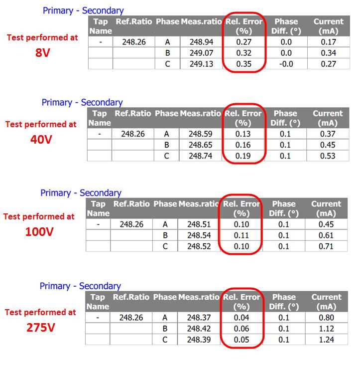
5
1 K Hinds 2012 TRANSFORMERS
 1 K Hinds 2012 TRANSFORMERS A transformer changes electrical energy of a given voltage into electrical energy at a different voltage level. It consists of two coils which are not electrically connected,
86 chapter 2 Transformers
 86 chapter 2 Transformers Wb 1.2x10 3 0 1/60 2/60 3/60 4/60 5/60 6/60 t (sec) 1.2x10 3 FIGURE P2.2 2.3 A single-phase transformer has 800 turns on the primary winding and 400 turns on the secondary winding.
Transformers. Dr. Gamal Sowilam
 Transformers Dr. Gamal Sowilam OBJECTIVES Become familiar with the flux linkages that exist between the coils of a transformer and how the voltages across the primary and secondary are established. Understand
Practical Transformer on Load
 Practical Transformer on Load We now consider the deviations from the last two ideality conditions : 1. The resistance of its windings is zero. 2. There is no leakage flux. The effects of these deviations
PHYS 1444 Section 501 Lecture #20
 PHYS 1444 Section 501 Lecture #0 Monday, Apr. 17, 006 Transformer Generalized Faraday s Law Inductance Mutual Inductance Self Inductance Inductor Energy Stored in the Magnetic Field 1 Announcements Quiz
EEE3441 Electrical Machines Department of Electrical Engineering. Lecture. Basic Operating Principles of Transformers
 Department of Electrical Engineering Lecture Basic Operating Principles of Transformers In this Lecture Basic operating principles of following transformers are introduced Single-phase Transformers Three-phase
The power transformer
 ELEC0014 - Introduction to power and energy systems The power transformer Thierry Van Cutsem t.vancutsem@ulg.ac.be www.montefiore.ulg.ac.be/~vct November 2017 1 / 35 Power transformers are used: to transmit
Inductor and Transformer Design
 Inductor and Transformer Design 1 Introduction The conditioning of power flow in Power Electronic Systems (PES) is done through the use of electromagnetic elements (inductors and transformers). In this
PHYS 1444 Section 003 Lecture #19
 PHYS 1444 Section 003 Lecture #19 Monday, Nov. 14, 2005 Electric Generators DC Generator Eddy Currents Transformer Mutual Inductance Today s homework is homework #10, due noon, next Tuesday!! 1 Announcements
PHYS 1441 Section 001 Lecture #22 Wednesday, Nov. 29, 2017
 PHYS 1441 Section 001 Lecture #22 Chapter 29:EM Induction & Faraday s Law Transformer Electric Field Due to Changing Magnetic Flux Chapter 30: Inductance Mutual and Self Inductance Energy Stored in Magnetic
Magnetics. Important relationships. Magnetic quantities Analogies to electrical quantities
 Mor M. Peretz, Switch-Mode Power Supplies [3-1] Faraday s and Amper s laws Permeability Inductor Reluctance model Air gap Current crowding Inductor design Skin effect, proximity effect Losses Transformer
TRANSFORMER THEORY. Mutual Induction
 Transformers Transformers are used extensively for AC power transmissions and for various control and indication circuits. Knowledge of the basic theory of how these components operate is necessary to
Electrical Theory 2 Lessons for Fall Semester:
 Electrical Theory 2 Lessons for Fall Semester: Lesson 1 Magnetism Lesson 2 Introduction to AC Theory Lesson 3 Lesson 4 Capacitance and Capacitive Reactance Lesson 5 Impedance and AC Circuits Lesson 6 AC
Electromagnetic Induction
 Chapter 16 Electromagnetic Induction In This Chapter: Electromagnetic Induction Faraday s Law Lenz s Law The Transformer Self-Inductance Inductors in Combination Energy of a Current-Carrying Inductor Electromagnetic
Faraday Laws of Electromagnetic Induction CLIL LESSON
 Faraday Laws of Electromagnetic Induction CLIL LESSON Experimental trials Michael Faraday-1931 This law shows the relationship between electric circuit and magnetic field A coil is connected to a galvanometer
Three phase transformer 1
 Three phase transformer 1 Electric Engineering Name Institution: Three phase transformer 2 Table of Contents Operation of transformer under no load... 3 Operation of transformer under load... 4 Circuit
DESIGN AND CONSTRUCTION OF 1500VA VARIABLE OUTPUT STEP DOWN TRANSFORMER
 DESIGN AND CONSTRUCTION OF 1500VA VARIABLE OUTPUT STEP DOWN TRANSFORMER OGUNDARE AYOADE B., OMOGOYE O. SAMUEL & OLUWASANYA OMOTAYO J. Department of Electrical/Electronic engineering, Lagos State Polytechnic,
ISSN: [IDSTM-18] Impact Factor: 5.164
![ISSN: [IDSTM-18] Impact Factor: 5.164](/thumbs/91/106796217.jpg "ISSN: [IDSTM-18] Impact Factor: 5.164") IJESRT INTERNATIONAL JOURNAL OF ENGINEERING SCIENCES & RESEARCH TECHNOLOGY A REVIEW OF ROUTINE TESTING ON DISTRIBUTION TRANSFORMER Sukhbir Singh 1, Parul Jangra 2, Anoop Bhagat 3, Vipin Saini 4 1 Assistant
IJESRT INTERNATIONAL JOURNAL OF ENGINEERING SCIENCES & RESEARCH TECHNOLOGY A REVIEW OF ROUTINE TESTING ON DISTRIBUTION TRANSFORMER Sukhbir Singh 1, Parul Jangra 2, Anoop Bhagat 3, Vipin Saini 4 1 Assistant
CHAPTER 2. Transformers. Dr Gamal Sowilam
 CHAPTER Transformers Dr Gamal Sowilam Introduction A transformer is a static machine. It is not an energy conversion device, it is indispensable in many energy conversion systems. A transformer essentially
By Gill ( ) PDF created with FinePrint pdffactory trial version
 PDF created with FinePrint pdffactory trial version") By Gill (www.angelfire.com/al4/gill ) 1 Introduction One of the main reasons of adopting a.c. system instead of d.c. for generation, transmission and distribution of electrical power is that alternatin
By Gill (www.angelfire.com/al4/gill ) 1 Introduction One of the main reasons of adopting a.c. system instead of d.c. for generation, transmission and distribution of electrical power is that alternatin
Chapter 2-1 Transformers
 Principles of Electric Machines and Power Electronics Chapter 2-1 Transformers Third Edition P. C. Sen Transformer application 1: power transmission Ideal Transformer Assumptions: 1. Negligible winding
TRANSFORMER OPERATION
 Chapter 3 TRANSFORMER OPERATION 1 A transformer is a static device (no moving parts) used to transfer energy from one AC circuit to another. This transfer of energy may involve an increase or decrease
APPLICATION NOTE - 018
 APPLICATION NOTE - 018 Power Transformers Background Power Transformers are used within an AC power distribution systems to increase or decrease the operating voltage to achieve the optimum transmission
Alternative Testing Techniques for Current Transformers. Dinesh Chhajer, PE Technical Support Group MEGGER
 Alternative Testing Techniques for Current Transformers Dinesh Chhajer, PE Technical Support Group MEGGER Agenda Current Transformer Definition and Fundamentals Current Transformer Applications o Metering
Understanding and Extracting Valuable Information from Basic and Advanced Power Transformer Testing Techniques
 Understanding and Extracting Valuable Information from Basic and Advanced Power Transformer Testing Techniques Charles Sweetser, Services Manager, PRIM Engineering, Waltham, Mass. Topics of Discussion
Exam 3 Review Session
 Exam 3 Review Session I will hold a review for Exam 3 which covers Chapters 27, 28, 29 and 30, on Wednesday November 7 th at 7:15pm in MPHY 205. Exam 3 will be given in class on Thursday, November 8 th.
148 Electric Machines
 148 Electric Machines 3.1 The emf per turn for a single-phase 2200/220- V, 50-Hz transformer is approximately 12 V. Calculate (a) the number of primary and secondary turns, and (b) the net cross-sectional
VOLTECHNOTES. Turns Ratio iss 4 Page 1 of 7
 VOLTECHNOTES Turns Ratio 104-113 iss 4 Page 1 of 7 Introduction Transformers are used in a wide array of electrical or electronic applications, providing functions that range from isolation and stepping
CHAPTER 4. Distribution Transformers
 CHAPTER 4 Distribution Transformers Introduction A transformer is an electrical device that transfers energy from one circuit to another purely by magnetic coupling. Relative motion of the parts of the
EEE 202 ELECTRO-TECHNIC LAB. PART 7 THEORY
 EEE 0 ELECTRO-TECHNIC LAB. PART 7 THEORY Yrd. Doç. Dr. Serhan Yarkan Arş. Gör. Dilara Albayrak İSTANBUL COMMERCE UNIVERSITY Contents EXAMINATION OF LC FILTERS... 0.1 INTRODUCTION... EXAMINATION OF TRANSFORMER...
Power Measurements and Basic Electrical Diagnostic Tests
 Power Measurements and Basic Electrical Diagnostic Tests Instrument Basics Burden VA Sources V and I Meters V and I KVL and KCL Kelvin Connection KVL and KCL Kelvin Connection 4-Wire Technique Exclude
Transformers 21.1 INTRODUCTION 21.2 MUTUAL INDUCTANCE
 21 Transformers 21.1 INTRODUCTION Chapter 12 discussed the self-inductance of a coil. We shall now examine the mutual inductance that exists between coils of the same or different dimensions. Mutual inductance
KNOW MORE ABOUT THE TRANSFORMERS. Glossary Transformers
 KNOW MORE ABOUT THE TRANSFORMERS Glossary Transformers Ambient temperature The existing temperature of the atmosphere surrounding a transformer installation. Ampere The practical unit of electric current.
Unit-4. Magnetic Circuits
 Unit-4 Magnetic Circuits Topics to be Discussed Magnetic Coupling. Coefficient of Coupling (k). Sign of Mutual Voltage. Dot Convention. September 9, 0 Magnetic Circuits Magnetically Coupled Circuits A
Back to the Basics Current Transformer (CT) Testing
 Testing") Back to the Basics Current Transformer (CT) Testing As test equipment becomes more sophisticated with better features and accuracy, we risk turning our field personnel into test set operators instead of
Back to the Basics Current Transformer (CT) Testing As test equipment becomes more sophisticated with better features and accuracy, we risk turning our field personnel into test set operators instead of
PART B. t (sec) Figure 1
 Figure 1") Code No: R16128 R16 SET 1 I B. Tech II Semester Regular Examinations, April/May 217 ELECTRICAL CIRCUIT ANALYSIS I (Electrical and Electronics Engineering) Time: 3 hours Max. Marks: 7 Note: 1. Question
Code No: R16128 R16 SET 1 I B. Tech II Semester Regular Examinations, April/May 217 ELECTRICAL CIRCUIT ANALYSIS I (Electrical and Electronics Engineering) Time: 3 hours Max. Marks: 7 Note: 1. Question
Power Factor & Harmonics
 Power Factor & Harmonics Andy Angrick 2014 Harmonic Distortion Harmonic problems are becoming more apparent because more equipment that produce harmonics are being applied to power systems Grounding Harmonics
VALLIAMMAI ENGINEERING COLLEGE
 VALLIAMMAI ENGINEERING COLLEGE SRM Nagar, Kattankulathur 603 203 DEPARTMENT OF ELECTRONICS AND INSTRUMENTATION ENGINEERING QUESTION BANK IV SEMESTER EI6402 ELECTRICAL MACHINES Regulation 2013 Academic
~=E.i!=h. Pre-certification Transformers
 7 Transformers Section 26 of the electrical code governs the use and installations of transformers. A transformer is a static device used to transfer energy from one alternating current circuit to another.
PHYS 1442 Section 004 Lecture #15
 PHYS 1442 Section 004 Lecture #15 Monday March 17, 2014 Dr. Andrew Brandt Chapter 21 Generator Transformer Inductance 3/17/2014 1 PHYS 1442-004, Dr. Andrew Brandt Announcements HW8 on Ch 21-22 will be
Code No: R Set No. 1
 Code No: R05310204 Set No. 1 III B.Tech I Semester Regular Examinations, November 2007 ELECTRICAL MACHINES-III (Electrical & Electronic Engineering) Time: 3 hours Max Marks: 80 Answer any FIVE Questions
Transformers handling and transport
 Special tests (Credit: http://www.breakbulk.com/wp-content/uploads/2015/02/20141117160247x.jpg) Transformers handling and transport Damages that may arise and how to find them Table of contents summary
Inductors and Transformers
 MEHRAN UNIVERSITY OF ENGINEERING AND TECHNOLOGY, JAMSHORO DEPARTMENT OF ELECTRONIC ENGINEERING ELECTRONIC WORKSHOP # 05 Inductors and Transformers Roll. No: Checked by: Date: Grade: Object: To become familiar
Transformers. gpmacademics.weebly.com
 TRANSFORMERS Syllabus: Principles of operation, Constructional Details, Losses and efficiency, Regulation of Transformer, Testing: OC & SC test. TRANSFORMER: It is a static device which transfers electric
A NOVEL METHOD FOR ENERGIZING TRANSFORMERS FOR REDUCING INRUSH CURRENTS
 A OVEL METHOD FOR EERGIZIG TRASFORMERS FOR REDUCIG IRUSH CURRETS M.B.B. Sharifian, Farhad Shahnia, Ali Shasvand 3, Iraj hasanzadeh 4,3,4 Faculty of Electrical and Computer Engineering, University of Tabriz,
Transformers. Department of Physics & Astronomy Texas Christian University, Fort Worth, TX. April 23, 2013
 Transformers Department of Physics & Astronomy Texas Christian University, Fort Worth, TX April 23, 2013 1 Introduction In the early nineteenth century, Hans Christian Øersted discovered that a magnetic
Chapter 16: Mutual Inductance
 Chapter 16: Mutual Inductance Instructor: Jean-François MILLITHALER http://faculty.uml.edu/jeanfrancois_millithaler/funelec/spring2017 Slide 1 Mutual Inductance When two coils are placed close to each
UNIVERSITY OF TECHNOLOGY By: Fadhil A. Hasan ELECTRICAL MACHINES
 UNIVERSITY OF TECHNOLOGY DEPARTMENT OF ELECTRICAL ENGINEERING Year: Second 2016-2017 By: Fadhil A. Hasan ELECTRICAL MACHINES І Module-II: AC Transformers o Single phase transformers o Three-phase transformers
Spring 2000 EE361: MIDTERM EXAM 1
 NAME: STUDENT NUMBER: Spring 2000 EE361: MIDTERM EXAM 1 This exam is open book and closed notes. Assume f=60 hz and use the constant µ o =4π 10-7 wherever necessary. Be sure to show all work clearly. 1.
Power. Power is the rate of using energy in joules per second 1 joule per second Is 1 Watt
 3 phase Power All we need electricity for is as a source of transport for energy. We can connect to a battery, which is a source of stored energy. Or we can plug into and electric socket at home or in
3. What is hysteresis loss? Also mention a method to minimize the loss. (N-11, N-12)
") DHANALAKSHMI COLLEGE OF ENGINEERING, CHENNAI DEPARTMENT OF ELECTRICAL AND ELECTRONICS ENGINEERING EE 6401 ELECTRICAL MACHINES I UNIT I : MAGNETIC CIRCUITS AND MAGNETIC MATERIALS Part A (2 Marks) 1. List
DHANALAKSHMI COLLEGE OF ENGINEERING, CHENNAI DEPARTMENT OF ELECTRICAL AND ELECTRONICS ENGINEERING EE 6401 ELECTRICAL MACHINES I UNIT I : MAGNETIC CIRCUITS AND MAGNETIC MATERIALS Part A (2 Marks) 1. List
Walchand Institute of Technology. Basic Electrical and Electronics Engineering. Transformer
 Walchand Institute of Technology Basic Electrical and Electronics Engineering Transformer 1. What is transformer? explain working principle of transformer. Electrical power transformer is a static device
El-Hawary, M.E. The Transformer Electrical Energy Systems. Series Ed. Leo Grigsby Boca Raton: CRC Press LLC, 2000
 El-Hawary, M.E. The Transformer Electrical Energy Systems. Series Ed. Leo Grigsby Boca Raton: CRC Press LLC, 000 97 Chapter 4 THE TRANSFORMER 4. NTRODUCTON The transformer is a valuable apparatus in electrical
EE2022 Electrical Energy Systems
 EE0 Electrical Energy Systems Lecture : Transformer and Per Unit Analysis 7-0-0 Panida Jirutitijaroen Department of Electrical and Computer Engineering /9/0 EE0: Transformer and Per Unit Analysis by P.
Electrical Machines I : Transformers
 UNIT TRANSFORMERS PART A (Q&A) 1. What is step down transformer? The transformer used to step down the voltage from primary to secondary is called as step down transformer. (Ex: /11).. Draw the noload
PART 1 OWNER/APPLICANT INFORMATION
 CALHOUN COUNTY ELECTRIC COOP. ASSN. Application for Operation of Customer-Owned Generation This application should be completed as soon as possible and returned to the Cooperative in order to begin processing
MATHEMATICAL MODELING OF POWER TRANSFORMERS
 MATHEMATICAL MODELING OF POWER TRANSFORMERS Mostafa S. NOAH Adel A. SHALTOUT Shaker Consultancy Group, Cairo University, Egypt Cairo, +545, mostafanoah88@gmail.com Abstract Single-phase and three-phase
GLOSSARY OF TERMS FLUX DENSITY:
 ADSL: Asymmetrical Digital Subscriber Line. Technology used to transmit/receive data and audio using the pair copper telephone lines with speed up to 8 Mbps. AMBIENT TEMPERATURE: The temperature surrounding
VOLTECHNOTES. Transformer Basics VPN /1
 Transformer Basics VPN 104-039/1 TRANSFORMER BASICS Introduction Transformer design and test are sometimes viewed as an art rather than a science. Transformers are imperfect devices, and there will be
Basics of electrical transformer
 Visit: https://engineeringbasic.com Complete basics and theory of Electrical Transformer Electrical Transformer is the most used electrical machine in power system. Both in the power transmission and distribution
Transformer Factory Testing
 Transformer Factory Testing John J. Foschia Test Engineer John.Foschia@spx.com September 2018 Reasons for Testing Compliance with user specifications Assessment of quality and reliability Verification
GENERATOR INTERCONNECTION APPLICATION FOR ALL PROJECTS WITH AGGREGATE GENERATOR OUTPUT OF MORE THAN 2 MW
 GENERATOR INTERCONNECTION APPLICATION FOR ALL PROJECTS WITH AGGREGATE GENERATOR OUTPUT OF MORE THAN 2 MW Electric Utility Contact Information DTE Energy Interconnection Coordinator One Energy Plaza, SB
Table of Contents. Table of Figures. Table of Tables
 Abstract The aim of this report is to investigate and test a transformer and check if it is good to use by doing the following tests continuity test, insulation test, polarity test, open circuit test,
General Licensing Class Circuits
 General Licensing Class Circuits Valid July 1, 2011 Through June 30, 2015 1 Amateur Radio General Class Element 3 Course Presentation ELEMENT 3 SUB-ELEMENTS (Groupings) Your Passing CSCE Your New General
Discipline Electrical Testing Issue Date Certificate Number T-2837 Valid Until Last Amended on - Page 1 of 6 LOCATION 1
 Post: Last Amended on - Page 1 of 6 LOCATION 1 I. TRANSFORMERS AND REACTORS 1. 500 MVA, 765 kv 500 MVA, 400 kv Ratio & Polarity Check Magnetic Balance & Magnetizing Current Measurement at Low Voltage Vector
SOUTH CENTRAL INDIANA REMC Application for Operation of Member-Owned Small Power Generation Systems
 SOUTH CENTRAL INDIANA REMC Application for Operation of Member-Owned Small Power Generation Systems This application should be completed as soon as possible and returned to the Cooperative in order to
TRANSFORMERS PART A. 2. What is the turns ratio and transformer ratio of transformer? Turns ratio = N2/ N1 Transformer = E2/E1 = I1/ I2 =K
 UNIT II TRANSFORMERS PART A 1. Define a transformer? A transformer is a static device which changes the alternating voltage from one level to another. 2. What is the turns ratio and transformer ratio of
Transformers. Objectives
 Transformers Objectives Explain mutual inductance Describe how a transformer is constructed and how it works Explain how a step-up transformer works Explain how a step-down transformer works Discuss the
ISSN: X Impact factor: (Volume 3, Issue 6) Available online at Modeling and Analysis of Transformer
 Available online at Modeling and Analysis of Transformer") ISSN: 2454-132X Impact factor: 4.295 (Volume 3, Issue 6) Available online at www.ijariit.com Modeling and Analysis of Transformer Divyapradeepa.T Department of Electrical and Electronics, Rajalakshmi Engineering
ISSN: 2454-132X Impact factor: 4.295 (Volume 3, Issue 6) Available online at www.ijariit.com Modeling and Analysis of Transformer Divyapradeepa.T Department of Electrical and Electronics, Rajalakshmi Engineering
ENGINEERING DATA SUBMITTAL For the Interconnection of Generation System
 WHO SHOULD FILE THIS SUBMITTAL: Anyone in the final stages of interconnecting a Generation System with Nodak Electric Cooperative, Inc. This submittal shall be completed and provided to Nodak Electric
Aligarh College of Engineering & Technology (College Code: 109) Affiliated to UPTU, Approved by AICTE Electrical Engg.
 Affiliated to UPTU, Approved by AICTE Electrical Engg.") Aligarh College of Engineering & Technology (College Code: 19) Electrical Engg. (EE-11/21) Unit-I DC Network Theory 1. Distinguish the following terms: (a) Active and passive elements (b) Linearity and
Aligarh College of Engineering & Technology (College Code: 19) Electrical Engg. (EE-11/21) Unit-I DC Network Theory 1. Distinguish the following terms: (a) Active and passive elements (b) Linearity and
Transformer. V1 is 1.0 Vp-p at 10 Khz. William R. Robinson Jr. p1of All rights Reserved
 V1 is 1.0 Vp-p at 10 Khz Step Down Direction Step Up Direction William R. Robinson Jr. p1of 24 Purpose To main purpose is to understand the limitations of the B2Spice simulator transformer model that I
1. If the flux associated with a coil varies at the rate of 1 weber/min,the induced emf is
 1. f the flux associated with a coil varies at the rate of 1 weber/min,the induced emf is 1 1. 1V 2. V 60 3. 60V 4. Zero 2. Lenz s law is the consequence of the law of conservation of 1. Charge 2. Mass
Operating principle of a transformer
 Transformers Operating principle of a transformer Transformers are stationary electrical machines which transmit energy from systems with certain current and voltage values into systems with generally
UNIT II MEASUREMENT OF POWER & ENERGY
 UNIT II MEASUREMENT OF POWER & ENERGY Dynamometer type wattmeter works on a very simple principle which is stated as "when any current carrying conductor is placed inside a magnetic field, it experiences
Exercise 10. Transformers EXERCISE OBJECTIVE DISCUSSION OUTLINE DISCUSSION. Introduction to transformers
 Exercise 10 Transformers EXERCISE OBJECTIVE When you have completed this exercise, you will be familiar with the basic operating principles of transformers, as well as with the different ratios of transformers:
WELCOME TO THE LECTURE
 WLCOM TO TH LCTUR ON TRNFORMR Single Phase Transformer Three Phase Transformer Transformer transformer is a stationary electric machine which transfers electrical energy (power) from one voltage level
The synchronous machine as a component in the electric power system
 1 The synchronous machine as a component in the electric power system dφ e = dt 2 lectricity generation The synchronous machine is used to convert the energy from a primary energy resource (such as water,
EASTERN ILLINI ELECTRIC COOPERATIVE Application for Operation of Member-Owned Generation
 EASTERN ILLINI ELECTRIC COOPERATIVE Application for Operation of Member-Owned Generation This application is to be completed and returned to the Cooperative member service representative in order to begin
Placement Paper For Electrical
 Placement Paper For Electrical Q.1 The two windings of a transformer is (A) conductively linked. (B) inductively linked. (C) not linked at all. (D) electrically linked. Ans : B Q.2 A salient pole synchronous
Advanced electromagnetism and electromagnetic induction
 Advanced electromagnetism and electromagnetic induction This worksheet and all related files are licensed under the Creative Commons Attribution License, version 1.0. To view a copy of this license, visit
PTTS series. Power Transformer Test System. Scope of Work:
 PTTS series Power Transformer Test System components insure the customer years of reliable service from their transformer test system. 750kV Class Power Transformer Test Lab PTTS series power transformer
Example of Transformer Connections and Ground Currents
 1 Example of Transformer Connections and Ground Currents 2 Y-Y transformer and ground currents Assume an unbalanced current only in phase a and no current in phases b and c This could lead to high unwanted
ELECTRICAL ENGINEERING ESE TOPIC WISE OBJECTIVE SOLVED PAPER-II
 ELECTRICAL ENGINEERING ESE TOPIC WISE OBJECTIVE SOLVED PAPER-II From (1992 2017) Office : F-126, (Lower Basement), Katwaria Sarai, New Delhi-110016 Phone : 011-26522064 Mobile : 8130909220, 9711853908
Practical Tricks with Transformers. Larry Weinstein K0NA
 Practical Tricks with Transformers Larry Weinstein K0NA Practical Tricks with Transformers Quick review of inductance and magnetics Switching inductive loads How many voltages can we get out of a $10 Home
Code No: R Set No. 1
 Code No: R05220204 Set No. 1 II B.Tech II Semester Supplimentary Examinations, Aug/Sep 2007 ELECTRICAL MACHINES-II (Electrical & Electronic Engineering) Time: 3 hours Max Marks: 80 Answer any FIVE Questions
Bus protection with a differential relay. When there is no fault, the algebraic sum of circuit currents is zero
 Bus protection with a differential relay. When there is no fault, the algebraic sum of circuit currents is zero Consider a bus and its associated circuits consisting of lines or transformers. The algebraic
M.B.S PUBLIC SCHOOL PHYSICS INVESTIGATORY PROJECT TRANSFORMERS BY:- AYASHKANT MISHRA. STD:-XII SEC:-A ROLL NO :
 M.B.S PUBLIC SCHOOL PHYSICS INVESTIGATORY PROJECT TRANSFORMERS BY:- AYASHKANT MISHRA. STD:-XII SEC:-A ROLL NO :- 2014-15 M.B.S Public school Department of physics CERTIFICATE This is to certify that Ayashkant
Glossary of Common Magnetic Terms
 Glossary of Common Magnetic Terms Copyright by Magnelab, Inc. 2009 Air Core A term used when no ferromagnetic core is used to obtain the required magnetic characteristics of a given coil. (see Core) Ampere
Owner/Customer Name: Mailing Address: City: County: State: Zip Code: Phone Number: Representative: Address: Fax Number:
 Interconnection of a Customer-Owned Renewable Generation System of Greater than 100 KW and Less than or Equal to 1 MW to the LCEC Electric Grid Tier 3 Application and Compliance Form Instructions: Complete
PART A. 1. List the types of DC Motors. Give any difference between them. BTL 1 Remembering
 UNIT I DC MACHINES Three phase circuits, a review. Construction of DC machines Theory of operation of DC generators Characteristics of DC generators Operating principle of DC motors Types of DC motors
Electric Transformer. Specifically, for each coil: Since the rate of change in flux through single loop of each coil are approximately the same,
 Electric Transformer Safety and Equipment Computer with PASCO 850 Universal Interface and PASCO Capstone Coils Set 3 Double Banana Cables PASCO Voltage Sensor (DIN to Banana cable with slip-on Alligator
APPLICATION FOR INTERCONNECTION & OPERATIONS OF MEMBER-OWNED GENERATION
 APPLICATION FOR INTERCONNECTION & OPERATIONS OF MEMBER-OWNED GENERATION This application should be completed and returned to in order to begin processing the request for interconnecting as required by
Electric Circuits II Magnetically Coupled Circuits. Dr. Firas Obeidat
 Electric Circuits II Magnetically Coupled Circuits Dr. Firas Obeidat 1 Table of contents 1 Mutual Inductance 2 Dot Convention 3 Analyze Circuits Involving Mutual Inductance 4 Energy in a Coupled Circuit
SHRI RAMSWAROOP MEMORIAL COLLEGE OF ENGG. & MANAGEMENT
 SHRI RAMSWAROOP MEMORIAL COLLEGE OF ENGG. & MANAGEMENT B.Tech. [SEM I (CE,EC,EE,EN)] QUIZ TEST-3 (Session: 2012-13) Time: 1 Hour ELECTRICAL ENGINEERING Max. Marks: 30 (EEE-101) Roll No. Academic/26 Refer/WI/ACAD/18
Core Technology Group Application Note 1 AN-1
 Measuring the Impedance of Inductors and Transformers. John F. Iannuzzi Introduction In many cases it is necessary to characterize the impedance of inductors and transformers. For instance, power supply
EE 340 Power Transformers
 EE 340 Power Transformers Preliminary considerations A transformer is a device that converts one AC voltage to another AC voltage at the same frequency. It consists of one or more coil(s) of wire wrapped
Power Electronics. Prof. B. G. Fernandes. Department of Electrical Engineering. Indian Institute of Technology, Bombay.
 Power Electronics Prof. B. G. Fernandes Department of Electrical Engineering Indian Institute of Technology, Bombay Lecture - 28 So far we have studied 4 different DC to DC converters. They are; first
Turn-to-Turn Fault Detection in Transformers Using Negative Sequence Currents
 Turn-to-Turn Fault Detection in Transformers Using Negative Sequence Currents Mariya Babiy 1, Rama Gokaraju 1, Juan Carlos Garcia 2 1 University of Saskatchewan, Saskatoon, Canada 2 Manitoba HVDC Research
Unit FE-5 Foundation Electricity: Electrical Machines
 Unit FE-5 Foundation Electricity: Electrical Machines What this unit is about Power networks consist of large number of interconnected hardware. This unit deals specifically with two types of hardware: