3D/SiP Advanced Packaging Symposium Session II: Wafer Level Integration & Processing April 29, 2008 Durham, NC
|
|
|
- Oswin Grant
- 6 years ago
- Views:
Transcription
1 3D/SiP Advanced Packaging Symposium Session II: Wafer Level Integration & Processing April 29, 2008 Durham, NC Off-Chip Coaxial to Coplanar Transition Using a MEMS Trench Monther Abusultan & Brock J. LaMeres Montana State University Bozeman, MT 1
2 Problem Statement System Performance in VLSI Designs is Limited by Package Interconnect 1) Signal Path Reflections - Unwanted Switching - Edge Speed Degradation 2) Signal Coupling - NE/FE Cross-talk - Power Supply Droop - Ground Bounce On-Chip Performance is outpacing Off-Chip interconnect 1) Emerging problem of getting high speed signals from chip-to-chip 2) This problem will continue as transistors keep getting faster 2

3 Why is packaging limiting performance? Today s Package Interconnect Looks Inductive - Long interconnect paths - Large return loops Wire Bond Inductance (~2.8nH) L I Today s Package Impedance is Not Controlled or Shielded 3
 Integrating functionality onto a single IC has limitations: -")
 Integrating multiple die onto the same package with wire bonds is an optimal balance However, we're back to the")
4 The Trend Toward System in Package (SiP) Moving more functionality on package reduces the amount of times a signal needs to traverse level 2 interconnect (package-to-pcb) Integrating functionality onto a single IC has limitations: - Reduced yield, suboptimal material selection (CMOS vs. GaAs vs. SiGe) Integrating multiple die onto the same package with wire bonds is an optimal balance However, we're back to the problem of unshielded, uncontrolled wire bonds 4
")
5 Proposed Solution A New Chip-to-Chip Interconnect Technology Off-Chip Coaxial Launch - Exploit Advances in MEMS process technology - Target System in Package (SiP) applications 5

6 Proposed Solution A New Chip-to-Chip Interconnect Technology Application - High speed chip-to-chip signals require controlled impedance and shielding - Additional process step converts perimeter wire-bond pads to coaxial launch. - Step 1: Design, Model, and Fabricate interconnection between side-by-side die - Step 2: Investigate Vertically Stacked Die Interconnect 6

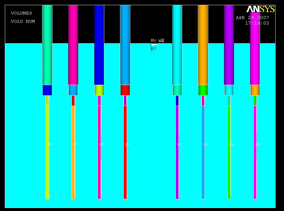
7 Proposed Solution A New Chip-to-Chip Interconnect Technology Processing - Etch a trench into the Silicon substrate to hold the coaxial cable - The center conductor is connected to a signal trace on-chip - A coplanar transmission line is used on-chip to provide connection to the signal and to the coaxial ground shield. 7


8 Coaxial to Coplanar Launch Geometric Dependencies - Coaxial Line - The coax outer diameter is the key dimension - Our design evaluations Semi-Rigid Coax's from Micro-Coax (UT-013, UT-020) - 50 impedance requirement sets coaxial dimensions - Extension diameters dictated by mechanical reliability 8
 Imaginary Impedance due to Lossy Semiconductor Material 2) Potential for higher-order modes in addition")
9 Coaxial to Coplanar Launch Geometric Dependencies - Coplanar Line - The ground separation is dictated by the outer diameter of the coaxial line G S G - 50 impedance set by material properties & signal trace width NOTE: On-Chip Coplanar Transmission Line has: 1) Imaginary Impedance due to Lossy Semiconductor Material 2) Potential for higher-order modes in addition to TEM 9


10 Coaxial to Coplanar Launch Geometric Dependencies - Trench - The trench must be wide enough to accept the coaxial outer diameter - The depth must place the coaxial center conductor on top of the coplanar signal trace - Using inscribed octagonal geometries sets width of trench - Anisotropic etch rate dictates angle of trench sidewall. 10


11 Coaxial to Coplanar Launch Geometric Dependencies Channel Spacing - Spacing of adjacent trenches must accommodate coax protrusion 11

12 Coaxial to Coplanar Launch Geometric Dependencies Transition Region - Length of sidewall dictated by anisotropic etch rate. - Overlapping lengths dictated by mechanical reliability 12
13 Coaxial to Coplanar Launch Summary of Dimensions - 2 Micro-Coax s are evaluated (UT-013, UT-020) - Each coax size influences the trench and coplanar transmission line dimensions Region Parameter Units Coaxial Line UT-013 UT-020 Coaxial Structure D oc m Coplanar Structure D od m D cc m T sig m 1 1 T ox m W sig m W gnd m S copl m S ss m Trench Structure W ttop m W tbot m W tsw m H tsw m Transition Region L trench m L dext m L sw m L cext m L ccov m
 14")
14 Coaxial to Coplanar Launch Impedance Discontinuities - Between the coax and coplanar T-lines, there are regions of impedance discontinuities - These add reflections and risetime degradation between the two ideal transmission line structures (i.e., the coaxial and coplanar lines) 14
15 Modeling Approach EM Field Solvers - Due to the complexity of the structure, a field solver is used to extract the characteristic impedance (Z 0 ) and propagation constant (g) -Z 0 andgare complex for signal propagation on the integrated circuit due to the use of a semiconductor substrate material. -Z 0 is real inside of the coaxial transmission line - We used Electromagnetic Design Systems (EMDS) from Agilent Technologies to perform 2D and 3D field simulations 15
16 Modeling Approach Our Approach 1) Extract Z 0 andg for each different Cross-Section within the transition using a 2D simulation 2) Import parameters into SPICE to perform transient simulations on the structures ability to transmit high speed signals 16


17 Modeling Results (XC1) Field Solder Results Z 0 = 52 + j26 g = j615 GND SIG Symmetry Axis GND SIG Symmetry Axis Electric Fields Magnetic Fields 17


18 Modeling Results (XC2) Field Solder Results Z 0 = 50 + j25 g = j604 GND SIG Symmetry Axis GND SIG Symmetry Axis Electric Fields Magnetic Fields 18


19 Modeling Results (XC3) Field Solder Results Z 0 = j3 g = 10 + j269 SIG SIG GND Symmetry Axis GND Symmetry Axis Electric Fields Magnetic Fields 19


20 Modeling Results (XC4) XC4 Field Solver Results Z 0 =128 + j1 g = 4 + j239 r1 r2 rms SIG SIG GND Symmetry Axis GND Symmetry Axis Electric Fields Magnetic Fields 20


21 Modeling Results (XC5) XC5 Field Solver Results Z 0 = j1 g = 3 + j229 r1 r2 SIG SIG GND Symmetry Axis GND Symmetry Axis Electric Fields Magnetic Fields 21


22 Modeling Results (XC6) XC6 Field Solver Results Z 0 = j1 g = 5 + j276 rc r1 r2 SIG SIG GND Symmetry Axis GND Symmetry Axis Electric Fields Magnetic Fields 22

23 Modeling Results (XC7) XC7 Field Solver Results Z 0 = 50 + j0 g = 0 + j296 rcrc r2 GND SIG Symmetry Axis GND SIG Symmetry Axis Electric Fields Magnetic Fields 23


24 Modeling Results (XC8) XC8 Field Solver Results Z 0 = 50 + j0 g = 0 + j296 rcrc SIG SIG GND Electric Fields GND Magnetic Fields 24


25 Modeling Results Field Solver Results Summary Region Z 0 g XC j j615 XC j j604 XC j j269 XC j1 4 + j239 XC j1 3 + j229 XC j1 5 + j276 XC j0 0 + j296 XC j0 0 + j296 Electric Fields Magnetic Fields 25
 -")


26 Electrical Evaluation (Comparison to Wirebond) - Comparing to a chip-to-chip application where coplanar lines are used on-chip (35ps risetime) Signal Path 1: Using a G/S/G wirebond interconnect structure Signal Path 2: Using the new coaxial launch structure 26
27 Spatial Evaluation Wire bond Comparison - Is this interconnect comparable in size to that of the pads for wire bonding? - We evaluate against 100 m x 100 m pad requirements for wire bond in G-S-G configuration with 100 m spacing Results Region Parameter Units Coaxial Line UT-013 UT-020 Coaxial Structure D oc m Coplanar Structure D od m D cc m T sig m 1 1 T ox m W sig m W gnd m S copl m S ss m Trench Structure W ttop m W tbot m Wire Bond Pads for G-S-G: = 3*(W pad ) + 2*(W space ) = 3*(100 m) + 2*(100 m) = 500 m - Coaxial Launch for G-S-G: W tsw m H tsw m Transition Region L trench m L dext m L sw m L cext m L ccov m = W ttop + 2*W gnd = 349 m + 2*100 m = 549 m only 9.8% more area required 27
28 Electrical Evaluation (Parasitics) Electrical Evaluation - Interconnect comparison Coax length = 3mm Wire bond length = 3mm Results - Versus wire bond: Parameter Units Wire Bond Coaxial Line L' nh/m C' pf/m Zo L 3mm nh C 3mm pf Inductance reduced by 57% Impedance reduced by 66% - Note: Interconnect is now Shielded and has Controlled Impedance 28
29 Electrical Evaluation (TDR/TDT) Wirebond = 34% reflection Coax Launch = 8% reflection 29
 Eye Diagrams of a")

30 Electrical Evaluation (Eye Diagram) Eye Diagrams of a 5Gb/s, PRBS for a Load Terminated System Wire bond Coplanar to Coax 30
31 Summary 1) A new SiP interconnect was presented and compared to current technology - Coaxial to Coplanar launch using MEMS trench - Selective processing for high-speed nets 2) Spatially this interconnect takes similar area requirements for G:S:G 3) Electrically this interconnect has the potential to perform faster - Controlled impedance reduces reflections - Shielded interconnect eliminates signal coupling 4) Next Steps - Fabrication underway at Montana State - Measurements on prototypes expected during summer of


32 Questions? 32
Fabrication Process For A Novel High Speed Coplanar-to-Coaxial Off-Chip Interconnect
 Fabrication Process For A Novel High Speed Coplanar-to-Coaxial Off-Chip Interconnect Chris McIntosh, Student Member, IEEE and Brock J. ameres, Member, IEEE Electrical & Computer Engineering Department
Fabrication Process For A Novel High Speed CoPlanar-to-Coaxial Off-Chip Interconnect
 Advanced Packaging : Advanced Packaging I Session We-A-2 September 3, 2008 Fabrication Process For A Novel High Speed oplanar-to-oaxial Off-hip Interconnect hris McIntosh & Brock J. ameres Montana State
Off-Chip Coaxial to Microstrip Transition Using MEMs Trench
 Off-Chip Coaxial to Microstrip Transition Using MEMs Trench Brock J. LaMeres, Member, IEEE and Chris McIntosh, Student Member, IEEE Dept of Electrical and Computer Engineering Montana State University
NOVEL DIE-TO-DIE COAXIAL INTERCONNECT SYSTEM FOR USE IN SYSTEM-IN-PACKAGE APPLICATIONS. Christopher Michael McIntosh
 NOVEL DIE-TO-DIE COAXIAL INTERCONNECT SYSTEM FOR USE IN SYSTEM-IN-PACKAGE APPLICATIONS by Christopher Michael McIntosh A thesis submitted in partial fulfillment of the requirements for the degree of Master
Compensation for Simultaneous Switching Noise in VLSI Packaging Brock J. LaMeres University of Colorado September 15, 2005
 Compensation for Simultaneous Switching Noise in VLSI Packaging Brock J. LaMeres University of Colorado 1 Problem Statement Package Interconnect Limits VLSI System Performance The three main components
Physical RF Circuit Techniques and Their Implications on Future Power Module and Power Electronic Design
 Physical RF Circuit Techniques and Their Implications on Future Power Module and Power Electronic Design Adam Morgan 5-5-2015 NE IMAPS Symposium 2015 Overall Motivation Wide Bandgap (WBG) semiconductor
Optimization of Wafer Level Test Hardware using Signal Integrity Simulation
 June 7-10, 2009 San Diego, CA Optimization of Wafer Level Test Hardware using Signal Integrity Simulation Jason Mroczkowski Ryan Satrom Agenda Industry Drivers Wafer Scale Test Interface Simulation Simulation
Characterization Methodology for High Density Microwave Fixtures. Dr. Brock J. LaMeres, Montana State University
 DesignCon 2008 Characterization Methodology for High Density Microwave Fixtures Dr. Brock J. LaMeres, Montana State University lameres@ece.montana.edu Brent Holcombe, Probing Technology, Inc brent.holcombe@probingtechnology.com
Chapter 2. Literature Review
 Chapter 2 Literature Review 2.1 Development of Electronic Packaging Electronic Packaging is to assemble an integrated circuit device with specific function and to connect with other electronic devices.
Technology in Balance
 Technology in Balance A G1 G2 B Basic Structure Comparison Regular capacitors have two plates or electrodes surrounded by a dielectric material. There is capacitance between the two conductive plates within
Signal Integrity Modeling and Measurement of TSV in 3D IC
 Signal Integrity Modeling and Measurement of TSV in 3D IC Joungho Kim KAIST joungho@ee.kaist.ac.kr 1 Contents 1) Introduction 2) 2.5D/3D Architectures with TSV and Interposer 3) Signal integrity, Channel
Microcircuit Electrical Issues
 Microcircuit Electrical Issues Distortion The frequency at which transmitted power has dropped to 50 percent of the injected power is called the "3 db" point and is used to define the bandwidth of the
Evaluation of Package Properties for RF BJTs
 Application Note Evaluation of Package Properties for RF BJTs Overview EDA simulation software streamlines the development of digital and analog circuits from definition of concept and estimation of required
Flip-Chip for MM-Wave and Broadband Packaging
 1 Flip-Chip for MM-Wave and Broadband Packaging Wolfgang Heinrich Ferdinand-Braun-Institut für Höchstfrequenztechnik (FBH) Berlin / Germany with contributions by F. J. Schmückle Motivation Growing markets
Session 4: Mixed Signal RF
 Sophia Antipolis October 5 th & 6 th 2005 Session 4: Mixed Signal RF Technology, Design and Manufacture of RF SiP Chris Barratt, Michel Beghin, Insight SiP Insight SiP Summary Introduction Definition of
Chapter 2 Low-Cost High-Bandwidth Millimeter Wave Leadframe Packages
 Chapter 2 Low-Cost High-Bandwidth Millimeter Wave Leadframe Packages Eric A. Sanjuan and Sean S. Cahill Abstract As integrated circuit speeds and bandwidth needs increase, low-cost packaging and interconnect
DesignCon Design of Gb/s Interconnect for High-bandwidth FPGAs. Sherri Azgomi, Altera Corporation
 DesignCon 2004 Design of 3.125 Gb/s Interconnect for High-bandwidth FPGAs Sherri Azgomi, Altera Corporation sazgomi@altera.com Lawrence Williams, Ph.D., Ansoft Corporation williams@ansoft.com CF-031505-1.0
A Simulation Study of Simultaneous Switching Noise
 A Simulation Study of Simultaneous Switching Noise Chi-Te Chen 1, Jin Zhao 2, Qinglun Chen 1 1 Intel Corporation Network Communication Group, LOC4/19, 9750 Goethe Road, Sacramento, CA 95827 Tel: 916-854-1178,
Figure 1. Inductance
 Tools for On-Chip Interconnect Inductance Extraction Jerry Tallinger OEA International Inc. 155 East Main Ave., Ste. 110 Morgan Hill, CA 95037 jerry@oea.com Haris Basit OEA International Inc. 155 East
Texas Instruments DisplayPort Design Guide
 Texas Instruments DisplayPort Design Guide April 2009 1 High Speed Interface Applications Introduction This application note presents design guidelines, helping users of Texas Instruments DisplayPort devices
FDTD SPICE Analysis of High-Speed Cells in Silicon Integrated Circuits
 FDTD Analysis of High-Speed Cells in Silicon Integrated Circuits Neven Orhanovic and Norio Matsui Applied Simulation Technology Gateway Place, Suite 8 San Jose, CA 9 {neven, matsui}@apsimtech.com Abstract
EQCD High Speed Characterization Summary
 EQCD High Speed Characterization Summary PRODUCT DESCRIPTION: A length of coaxial ribbon cable is terminated to a transition PCB break-out region onto which respective connectors are soldered. Three such
Considerations in High-Speed High Performance Die-Package-Board Co-Design. Jenny Jiang Altera Packaging Department October 2014
 Considerations in High-Speed High Performance Die-Package-Board Co-Design Jenny Jiang Altera Packaging Department October 2014 Why Co-Design? Complex Multi-Layer BGA Package Horizontal and vertical design
EVALUATION OF THE NEAR-FIELD INJECTION METHOD AT INTEGRATED CIRCUIT LEVEL
 1 EVALUATION OF THE NEAR-FIELD INJECTION METHOD AT INTEGRATED CIRCUIT LEVEL A. Boyer 1,2, B. Vrignon 3, J. Shepherd 3, M. Cavarroc 1,2 1 CNRS, LAAS, 7 avenue du colonel Roche, F-31400 Toulouse, France
Cost-minimized Double Die DRAM Packaging for Ultra-High Performance DDR3 and DDR4 Multi-Rank Server DIMMs
 Cost-minimized Double Die DRAM Packaging for Ultra-High Performance DDR3 and DDR4 Multi-Rank Server DIMMs Richard Crisp 1, Bill Gervasi 2, Wael Zohni 1, Bel Haba 3 1 Invensas Corp, 2902 Orchard Parkway,
License to Speed: Extreme Bandwidth Packaging
 License to Speed: Extreme Bandwidth Packaging Sean S. Cahill VP, Technology BridgeWave Communications Santa Clara, California, USA BridgeWave Communications Specializing in 60-90 GHz Providing a wireless
How to anticipate Signal Integrity Issues: Improve my Channel Simulation by using Electromagnetic based model
 How to anticipate Signal Integrity Issues: Improve my Channel Simulation by using Electromagnetic based model HSD Strategic Intent Provide the industry s premier HSD EDA software. Integration of premier
CHAPTER 4. Practical Design
 CHAPTER 4 Practical Design The results in Chapter 3 indicate that the 2-D CCS TL can be used to synthesize a wider range of characteristic impedance, flatten propagation characteristics, and place passive
Aries Kapton CSP socket
 Aries Kapton CSP socket Measurement and Model Results prepared by Gert Hohenwarter 5/19/04 1 Table of Contents Table of Contents... 2 OBJECTIVE... 3 METHODOLOGY... 3 Test procedures... 4 Setup... 4 MEASUREMENTS...
Suppression Techniques using X2Y as a Broadband EMI Filter IEEE International Symposium on EMC, Boston, MA
 Suppression Techniques using X2Y as a Broadband EMI Filter Jim Muccioli Tony Anthony Dave Anthony Dale Sanders X2Y Attenuators, LLC Erie, PA 16506-2972 www.x2y.com Email: x2y@x2y.com Bart Bouma Yageo/Phycomp
Optimization of Symmetric Spiral Inductors On Silicon Substrate
 Optimization of Symmetric Spiral Inductors On Silicon Substrate Hyunjin Lee, Joonho Gil, and Hyungcheol Shin Department of Electrical Engineering and Computer Science, KAIST -1, Guseong-dong, Yuseong-gu,
Introduction: Planar Transmission Lines
 Chapter-1 Introduction: Planar Transmission Lines 1.1 Overview Microwave integrated circuit (MIC) techniques represent an extension of integrated circuit technology to microwave frequencies. Since four
Demystifying Vias in High-Speed PCB Design
 Demystifying Vias in High-Speed PCB Design Keysight HSD Seminar Mastering SI & PI Design db(s21) E H What is Via? Vertical Interconnect Access (VIA) An electrical connection between layers to pass a signal
DesignCon Full Chip Signal and Power Integrity with Silicon Substrate Effect. Norio Matsui Dileep Divekar Neven Orhanovic
 DesignCon 2004 Chip-Level Physical Design Full Chip Signal and Power Integrity with Silicon Substrate Effect Norio Matsui Dileep Divekar Neven Orhanovic Applied Simulation Technology, Inc. 408-436-9070
Substrate Coupling in RF Analog/Mixed Signal IC Design: A Review
 Substrate Coupling in RF Analog/Mixed Signal IC Design: A Review Ashish C Vora, Graduate Student, Rochester Institute of Technology, Rochester, NY, USA. Abstract : Digital switching noise coupled into
Understanding, measuring, and reducing output noise in DC/DC switching regulators
 Understanding, measuring, and reducing output noise in DC/DC switching regulators Practical tips for output noise reduction Katelyn Wiggenhorn, Applications Engineer, Buck Switching Regulators Robert Blattner,
1 FUNDAMENTAL CONCEPTS What is Noise Coupling 1
 Contents 1 FUNDAMENTAL CONCEPTS 1 1.1 What is Noise Coupling 1 1.2 Resistance 3 1.2.1 Resistivity and Resistance 3 1.2.2 Wire Resistance 4 1.2.3 Sheet Resistance 5 1.2.4 Skin Effect 6 1.2.5 Resistance
MMIC/RFIC Packaging Challenges Webcast (July 28, AM PST 12PM EST)
") MMIC/RFIC Packaging Challenges Webcast ( 9AM PST 12PM EST) Board Package Chip HEESOO LEE Agilent EEsof 3DEM Technical Lead 1 Agenda 1. MMIC/RFIC packaging challenges 2. Design techniques and solutions
MMIC/RFIC Packaging Challenges Webcast ( 9AM PST 12PM EST) Board Package Chip HEESOO LEE Agilent EEsof 3DEM Technical Lead 1 Agenda 1. MMIC/RFIC packaging challenges 2. Design techniques and solutions
Introduction to VFTLP+
 Introduction to VFTLP+ VFTLP was originally developed to provide I-V characteristics of CDM protection and its analysis has been similar to that of TLP data used to analyze HBM protection circuits. VFTLP
Custom Interconnects Fuzz Button with Hardhat Test Socket/Interposer 1.00 mm pitch
 Custom Interconnects Fuzz Button with Hardhat Test Socket/Interposer 1.00 mm pitch Measurement and Model Results prepared by Gert Hohenwarter 12/14/2015 1 Table of Contents TABLE OF CONTENTS...2 OBJECTIVE...
Comparison of IC Conducted Emission Measurement Methods
 IEEE TRANSACTIONS ON INSTRUMENTATION AND MEASUREMENT, VOL. 52, NO. 3, JUNE 2003 839 Comparison of IC Conducted Emission Measurement Methods Franco Fiori, Member, IEEE, and Francesco Musolino, Member, IEEE
Design and Modeling of Through-Silicon Vias for 3D Integration
 Design and Modeling of Through-Silicon Vias for 3D Integration Ivan Ndip, Brian Curran, Gerhard Fotheringham, Jurgen Wolf, Stephan Guttowski, Herbert Reichl Fraunhofer IZM & BeCAP @ TU Berlin IEEE Workshop
Impedance Matching: Terminations
 by Barry Olney IN-CIRCUIT DESIGN PTY LTD AUSTRALIA column BEYOND DESIGN Impedance Matching: Terminations The impedance of the trace is extremely important, as any mismatch along the transmission path will
AWR. SIP Flow White Paper UNDERSTANDING AVAILABLE TOOLS FOR RF SYSTEM-IN-PACKAGE AND MULTI-CHIP-MODULE DESIGN AND OPTIMIZATION
 UNDERSTANDING AVAILABLE TOOLS FOR RF SYSTEM-IN-PACKAGE AND MULTI-CHIP-MODULE DESIGN AND OPTIMIZATION RF system-in-package (SiP) and multi-chip-module (MCM) designs present engineers with the challenge
Wafer-scale 3D integration of silicon-on-insulator RF amplifiers
 Wafer-scale integration of silicon-on-insulator RF amplifiers The MIT Faculty has made this article openly available. Please share how this access benefits you. Your story matters. Citation As Published
RECENTLY, interest in on-chip spiral inductors has surged
 IEEE JOURNAL OF SOLID-STATE CIRCUITS, VOL. 33, NO. 5, MAY 1998 743 On-Chip Spiral Inductors with Patterned Ground Shields for Si-Based RF IC s C. Patrick Yue, Student Member, IEEE, and S. Simon Wong, Senior
Microprobing with the Agilent 86100A Infiniium DCA
 Microprobing with the Agilent 86100A Infiniium DCA Application Note 1304-3 A guide to making accurate measurements with the Agilent 86100A Infiniium DCA and Time Domain Reflectometer using Cascade Microtech
Taking the Mystery out of Signal Integrity
 Slide - 1 Jan 2002 Taking the Mystery out of Signal Integrity Dr. Eric Bogatin, CTO, GigaTest Labs Signal Integrity Engineering and Training 134 S. Wolfe Rd Sunnyvale, CA 94086 408-524-2700 www.gigatest.com
Low Jitter, Low Emission Timing Solutions For High Speed Digital Systems. A Design Methodology
 Low Jitter, Low Emission Timing Solutions For High Speed Digital Systems A Design Methodology The Challenges of High Speed Digital Clock Design In high speed applications, the faster the signal moves through
Signal and Noise Measurement Techniques Using Magnetic Field Probes
 Signal and Noise Measurement Techniques Using Magnetic Field Probes Abstract: Magnetic loops have long been used by EMC personnel to sniff out sources of emissions in circuits and equipment. Additional
--- An integrated 3D EM design flow for EM/Circuit Co-Design
 ADS users group meeting 2009 Rome 13/05, Böblingen 14-15/05, Massy 16/06 --- An integrated 3D EM design flow for EM/Circuit Co-Design Motivations and drivers for co-design Throw-The-Die-Over-The-Wall,
Characterization of Alternate Power Distribution Methods for 3D Integration
 Characterization of Alternate Power Distribution Methods for 3D Integration David C. Zhang, Madhavan Swaminathan, David Keezer and Satyanarayana Telikepalli School of Electrical and Computer Engineering,
The Challenges of Differential Bus Design
 The Challenges of Differential Bus Design February 20, 2002 presented by: Arthur Fraser TechKnowledge Page 1 Introduction Background Historically, differential interconnects were often twisted wire pairs
The Inductance Loop Power Distribution in the Semiconductor Test Interface. Jason Mroczkowski Multitest
 The Inductance Loop Power Distribution in the Semiconductor Test Interface Jason Mroczkowski Multitest j.mroczkowski@multitest.com Silicon Valley Test Conference 2010 1 Agenda Introduction to Power Delivery
Parallel vs. Serial Inter-plane communication using TSVs
 Parallel vs. Serial Inter-plane communication using TSVs Somayyeh Rahimian Omam, Yusuf Leblebici and Giovanni De Micheli EPFL Lausanne, Switzerland Abstract 3-D integration is a promising prospect for
GaAs MMIC Non-Linear Transmission Line. Description Package Green Status
 GaAs MMIC Non-Linear Transmission Line NLTL-6273 1. Device Overview 1.1 General Description NLTL-6273 is a MMIC non-linear transmission line (NLTL) based comb generator. This NLTL offers excellent phase
High Speed Digital Systems Require Advanced Probing Techniques for Logic Analyzer Debug
 JEDEX 2003 Memory Futures (Track 2) High Speed Digital Systems Require Advanced Probing Techniques for Logic Analyzer Debug Brock J. LaMeres Agilent Technologies Abstract Digital systems are turning out
SHELLCASE-TYPE WAFER-LEVEL PACKAGING SOLUTIONS: RF CHARACTERIZATION AND MODELING
 SHELLCASE-TYPE WAFER-LEVEL PACKAGING SOLUTIONS: RF CHARACTERIZATION AND MODELING M Bartek 1, S M Sinaga 1, G Zilber 2, D Teomin 2, A Polyakov 1, J N Burghartz 1 1 Delft University of Technology, Lab of
DesignCon Effect of Power Plane Inductance on Power Delivery Networks. Shirin Farrahi, Cadence Design Systems
 DesignCon 2019 Effect of Power Plane Inductance on Power Delivery Networks Shirin Farrahi, Cadence Design Systems shirinf@cadence.com, 978-262-6008 Ethan Koether, Oracle Corp ethan.koether@oracle.com Mehdi
The Impact Of Signal Jumping Across Multiple Different Reference Planes On Electromagnetic Compatibility
 Copyright by Dr. Andrew David Norte, All Rights Reserved March 18 th, 2012 The Impact Of Signal Jumping Across Multiple Different Reference Planes On Electromagnetic Compatibility David Norte, PhD www.the-signal-and-power-integrity-institute.com
Through-Silicon-Via Inductor: Is it Real or Just A Fantasy?
 Through-Silicon-Via Inductor: Is it Real or Just A Fantasy? Umamaheswara Rao Tida 1 Cheng Zhuo 2 Yiyu Shi 1 1 ECE Department, Missouri University of Science and Technology 2 Intel Research, Hillsboro Outline
3D IC-Package-Board Co-analysis using 3D EM Simulation for Mobile Applications
 3D IC-Package-Board Co-analysis using 3D EM Simulation for Mobile Applications Darryl Kostka, CST of America Taigon Song and Sung Kyu Lim, Georgia Institute of Technology Outline Introduction TSV Array
Fuzz Button interconnects at microwave and mm-wave frequencies
 Fuzz Button interconnects at microwave and mm-wave frequencies David Carter * The Connector can no Longer be Ignored. The connector can no longer be ignored in the modern electronic world. The speed of
High Data Rate Characterization Report
 High Data Rate Characterization Report EQCD-020-39.37-STR-TTL-1 EQCD-020-39.37-STR-TEU-2 Mated with: QTE-020-01-X-D-A and QSE-020-01-X-D-A Description: 0.8mm High-Speed Coax Cable Assembly Samtec, Inc.
CIRCUITS. Raj Nair Donald Bennett PRENTICE HALL
 POWER INTEGRITY ANALYSIS AND MANAGEMENT I CIRCUITS Raj Nair Donald Bennett PRENTICE HALL Upper Saddle River, NJ Boston Indianapolis San Francisco New York Toronto Montreal London Munich Paris Madrid Capetown
Microcontroller Systems. ELET 3232 Topic 13: Load Analysis
 Microcontroller Systems ELET 3232 Topic 13: Load Analysis 1 Objective To understand hardware constraints on embedded systems Define: Noise Margins Load Currents and Fanout Capacitive Loads Transmission
DesignCon Impedance Matching Techniques for VLSI Packaging. Brock J. LaMeres, Agilent Technologies, Inc. Rajesh Garg, Texas A&M University
 DesignCon 2006 Impedance Matching Techniques for VLSI Packaging Brock J. LaMeres, Agilent Technologies, Inc. Rajesh Garg, Texas A&M University Kanupriva Gulati, Texas A&M University Sunil P. Khatri, Texas
Introduction to On-Wafer Characterization at Microwave Frequencies
 Introduction to On-Wafer Characterization at Microwave Frequencies Chinh Doan Graduate Student University of California, Berkeley Introduction to On-Wafer Characterization at Microwave Frequencies Dr.
Compact Distributed Phase Shifters at X-Band Using BST
 Integrated Ferroelectrics, 56: 1087 1095, 2003 Copyright C Taylor & Francis Inc. ISSN: 1058-4587 print/ 1607-8489 online DOI: 10.1080/10584580390259623 Compact Distributed Phase Shifters at X-Band Using
VLSI is scaling faster than number of interface pins
 High Speed Digital Signals Why Study High Speed Digital Signals Speeds of processors and signaling Doubled with last few years Already at 1-3 GHz microprocessors Early stages of terahertz Higher speeds
Objectives of transmission lines
 Introduction to Transmission Lines Applications Telephone Cable TV (CATV, or Community Antenna Television) Broadband network High frequency (RF) circuits, e.g., circuit board, RF circuits, etc. Microwave
Design Guide for High-Speed Controlled Impedance Circuit Boards
 IPC-2141A ASSOCIATION CONNECTING ELECTRONICS INDUSTRIES Design Guide for High-Speed Controlled Impedance Circuit Boards Developed by the IPC Controlled Impedance Task Group (D-21c) of the High Speed/High
The Design Challenge to Integrate High Performance Organic Packaging into High End ASIC Strategic Space Based Applications.
 The Design Challenge to Integrate High Performance Organic Packaging into High End ASIC Strategic Space Based Applications May 8, 2007 Abstract: The challenge to integrate high-end, build-up organic packaging
Synthesis of Optimal On-Chip Baluns
 Synthesis of Optimal On-Chip Baluns Sharad Kapur, David E. Long and Robert C. Frye Integrand Software, Inc. Berkeley Heights, New Jersey Yu-Chia Chen, Ming-Hsiang Cho, Huai-Wen Chang, Jun-Hong Ou and Bigchoug
Integration Techniques for MMICs and Chip Devices in LTCC Multichip Modules for Radio Frequencies
 Integration Techniques for MMICs and Chip Devices in LTCC Multichip Modules for Radio Frequencies R. Kulke *, W. Simon *, M. Rittweger *, I. Wolff *, S. Baker +, R. Powell + and M. Harrison + * Institute
Advanced Transmission Lines. Transmission Line 1
 Advanced Transmission Lines Transmission Line 1 Transmission Line 2 1. Transmission Line Theory :series resistance per unit length in. :series inductance per unit length in. :shunt conductance per unit
insert link to the published version of your paper
 Citation Niels Van Thienen, Wouter Steyaert, Yang Zhang, Patrick Reynaert, (215), On-chip and In-package Antennas for mm-wave CMOS Circuits Proceedings of the 9th European Conference on Antennas and Propagation
The Advantages of Integrated MEMS to Enable the Internet of Moving Things
 The Advantages of Integrated MEMS to Enable the Internet of Moving Things January 2018 The availability of contextual information regarding motion is transforming several consumer device applications.
A Simulation Methodology for Wirebonds Interconnects of Radiofrequency Integrated Circuits
 A Simulation Methodology for Wirebonds Interconnects of Radiofrequency Integrated Circuits Hercílio M. Cavalcanti 1 and Leandro T. Manera 2 1 Hercílio M. Cavalcanti, CTI Renato Archer, Campinas, São Paulo,
Digital Systems Power, Speed and Packages II CMPE 650
 Speed VLSI focuses on propagation delay, in contrast to digital systems design which focuses on switching time: A B A B rise time propagation delay Faster switching times introduce problems independent
Infinity Probe Mechanical Layout Rules
 Infinity Probe Mechanical Layout Rules APPLICATION NOTE Introduction The explosive growth of smart phones has led to advancements in communications protocols, such as 4G and 5G. This leads to technological
Silicon Interposers enable high performance capacitors
 Interposers between ICs and package substrates that contain thin film capacitors have been used previously in order to improve circuit performance. However, with the interconnect inductance due to wire
DesignCon East Feasibility of 40 to 50 Gbps NRZ Interconnect Design for Terabit Backplanes
 DesignCon East 2005 Feasibility of 40 to 50 Gbps NRZ Interconnect Design for Terabit Backplanes Roger Weiss, Paricon Technologies Corporation President, RWeiss@paricon-tech.com Scott McMorrow, Teraspeed
Design of the Power Delivery System for Next Generation Gigahertz Packages
 Design of the Power Delivery System for Next Generation Gigahertz Packages Madhavan Swaminathan Professor School of Electrical and Computer Engg. Packaging Research Center madhavan.swaminathan@ece.gatech.edu
Smart Devices of 2025
 Smart Devices of 2025 Challenges for Packaging of Future Device Technologies Steve Riches/Kevin Cannon Tribus-D Ltd CW Workshop 27 March 2018 E:mail: info@tribus-d.uk M: 07804 980 954 Assembly Technology
HV739 ±100V 3.0A Ultrasound Pulser Demo Board
 HV79 ±00V.0A Ultrasound Pulser Demo Board HV79DB Introduction The HV79 is a monolithic single channel, high-speed, high voltage, ultrasound transmitter pulser. This integrated, high performance circuit
2.5D & 3D Package Signal Integrity A Paradigm Shift
 2.5D & 3D Package Signal Integrity A Paradigm Shift Nozad Karim Technology & Platform Development November, 2011 Enabling a Microelectronic World Content Traditional package signal integrity vs. 2.5D/3D
A Miniaturized Multi-Channel TR Module Design Based on Silicon Substrate
 Progress In Electromagnetics Research Letters, Vol. 74, 117 123, 2018 A Miniaturized Multi-Channel TR Module Design Based on Silicon Substrate Jun Zhou 1, 2, *, Jiapeng Yang 1, Donglei Zhao 1, and Dongsheng
Design for EMI & ESD compliance DESIGN FOR EMI & ESD COMPLIANCE
 DESIGN FOR EMI & ESD COMPLIANCE All of we know the causes & impacts of EMI & ESD on our boards & also on our final product. In this article, we will discuss some useful design procedures that can be followed
Chapter 2. Inductor Design for RFIC Applications
 Chapter 2 Inductor Design for RFIC Applications 2.1 Introduction A current carrying conductor generates magnetic field and a changing current generates changing magnetic field. According to Faraday s laws
Lecture 020 ECE4430 Review II (1/5/04) Page 020-1
 Page 020-1") Lecture 020 ECE4430 Review II (1/5/04) Page 020-1 LECTURE 020 ECE 4430 REVIEW II (READING: GHLM - Chap. 2) Objective The objective of this presentation is: 1.) Identify the prerequisite material as taught
Lecture 020 ECE4430 Review II (1/5/04) Page 020-1 LECTURE 020 ECE 4430 REVIEW II (READING: GHLM - Chap. 2) Objective The objective of this presentation is: 1.) Identify the prerequisite material as taught
DesignCon 2003 High-Performance System Design Conference (HP3-5)
") DesignCon 2003 High-Performance System Design Conference (HP3-5) Logic Analyzer Probing Techniques for High-Speed Digital Systems Author/Presenter: Brock LaMeres Hardware Design Engineer Logic Analyzer
DesignCon 2003 High-Performance System Design Conference (HP3-5) Logic Analyzer Probing Techniques for High-Speed Digital Systems Author/Presenter: Brock LaMeres Hardware Design Engineer Logic Analyzer
Lecture 020 ECE4430 Review II (1/5/04) Page 020-1
 Page 020-1") Lecture 020 ECE4430 Review II (1/5/04) Page 020-1 LECTURE 020 ECE 4430 REVIEW II (READING: GHLM - Chap. 2) Objective The objective of this presentation is: 1.) Identify the prerequisite material as taught
Lecture 020 ECE4430 Review II (1/5/04) Page 020-1 LECTURE 020 ECE 4430 REVIEW II (READING: GHLM - Chap. 2) Objective The objective of this presentation is: 1.) Identify the prerequisite material as taught
TOP VIEW MAX9111 MAX9111
 19-1815; Rev 1; 3/09 EVALUATION KIT AVAILABLE Low-Jitter, 10-Port LVDS Repeater General Description The low-jitter, 10-port, low-voltage differential signaling (LVDS) repeater is designed for applications
High-Speed PCB Design Considerations
 December 2006 Introduction High-Speed PCB Design Considerations Technical Note TN1033 The backplane is the physical interconnection where typically all electrical modules of a system converge. Complex
PRELIMINARY PRELIMINARY
 Impedance Discontinuities of Right Angle Bends 90 degree, chamfered, and radial Augusto Panella Molex Incorporated Scott McMorrow SiQual, Inc. Introduction The results presented below are a portion of
POSSUM TM Die Design as a Low Cost 3D Packaging Alternative
 POSSUM TM Die Design as a Low Cost 3D Packaging Alternative The trend toward 3D system integration in a small form factor has accelerated even more with the introduction of smartphones and tablets. Integration
Gain Slope issues in Microwave modules?
 Gain Slope issues in Microwave modules? Physical constraints for broadband operation If you are a microwave hardware engineer you most likely have had a few sobering experiences when you test your new
A Technical Discussion of TDR Techniques, S-parameters, RF Sockets, and Probing Techniques for High Speed Serial Data Designs
 A Technical Discussion of TDR Techniques, S-parameters, RF Sockets, and Probing Techniques for High Speed Serial Data Designs Presenter: Brian Shumaker DVT Solutions, LLC, 650-793-7083 b.shumaker@comcast.net
Chapter 7 Introduction to 3D Integration Technology using TSV
 Chapter 7 Introduction to 3D Integration Technology using TSV Jin-Fu Li Department of Electrical Engineering National Central University Jungli, Taiwan Outline Why 3D Integration An Exemplary TSV Process