Electronic PRINCIPLES
|
|
|
- Pauline Wilson
- 6 years ago
- Views:
Transcription


1 MALVINO & BATES Electronic PRINCIPLES SEVENTH EDITION
2 Chapter 21 Active Filters
3 Topics Covered in Chapter 21 Ideal responses Approximate responses Passive ilters First-order stages VCVS unity-gain second-order low pass ilters Higher order ilters
4 Topics Covered in Chapter 21 (Continued) VCVS equal-component low pass ilters VCVS high pass ilters MFB bandpass ilters Bandstop ilters The all-pass ilter Biquadratic and state-variable ilters
5 A V Low-pass Ideal ilter responses A V BW Bandpass c 1 2 A V All-pass A V High-pass A V Bandstop c 1 2
6 Real ilter response Ideal (brickwall) ilters do not exist Real ilters have an approximate response The attenuation o an ideal ilter is in the stopband Real ilter attenuation is v out /v out(mid) : 3 db = db = db = 01
7 Approximate responses The passband is identiied by its low attenuation and its edge requency The stopband is identiied by its high attenuation and edge requency The order o a ilter is the number o reactive components
8 The order o a ilter In an LC type, the order is equal to the number o inductors and capacitors in the ilter In an RC type, the order is equal to the number o capacitors in the ilter In an active type, the order is approximately equal to the number o capacitors in the ilter
9 Filter approximations Butterworth (maximally lat response): rollo = 20n db/decade where n is the order o the ilter Chebyshev (equal ripple response): the number o ripples = n/2 Inverse Chebyshev (rippled stopband) Elliptic (optimum transition) Bessel (linear phase shit)
10 A V Butterworth Real low-pass ilter responses A V Chebyshev A V Bessel A V Inverse Chebyshev A V Elliptic Note: monotonic ilters have no ripple in the stopband
11 A V Butterworth Real bandpass ilter responses A V Chebyshev A V Bessel A V Inverse Chebyshev A V Elliptic
12 Passive ilters A low-pass LC ilter has a resonant requency and a Q The response is maximally lat when Q = 0707 As Q increases, a peak appears in the response, centered on the resonant requency
13 A second-order low-pass LC ilter L r = 1 2π LC v in C R 600 Ω v out R Q = XL L C R Q 955 mh 265 µf 1 khz mh 531 nf 1 khz mh 187 nf 1 khz 0707
14 The eect o Q on second-order response 20 db 6 db 0 db A Q = 10 (underdamped) Q = 2 (underdamped) Q = 0707 (critically damped) α = 1 Q rollo = 40 db/decade R or 0 The Butterworth response is critically damped The Bessel response is overdamped (Q = 0577 not graphed) The damping actor is α
15 First-order stages Have a single capacitor and one or more resistors Produce a Butterworth response because peaking is only possible in second-order or higher stages Can produce either a low-pass or a highpass response
16 Sallen-Key second-order low-pass ilter C 2 R R v in C 1 v out Q = 05 C 2 C 1 1 p = 2πR C 1 C 2 A v = 1 = pole requency
17 Second-order responses Most common and easy to implement and analyze Butterworth: Q = 0707; K c = 1 Bessel: Q = 0577; K c = 0786 Cuto requency: c = K c p Peaked response: Q > 0707 * 0 = K 0 p (the peaking requency) * c = K c p (the edge requency) * 3dB = K 3 p
18 Higher-order ilters Cascade second-order stages to obtain even-order response Cascade second-order stages plus one irst-order stage to obtain odd-order response The db attenuation is cumulative Filter design can be tedious and complex Tables and ilter-design sotware are used
19 VCVS equal component low-pass ilters The Sallen-Key equal component ilters control the Q by setting the voltage gain Higher Qs are diicult to get because o component tolerance
20 Sallen-Key equal-component ilter C v in R R R 2 A v = + 1 R 1 Q = p = 1 2πRC C R 1 R A v As A v approaches v out 3, this circuit becomes impractical and may oscillate
21 VCVS high-pass ilters Have the same coniguration as low-pass, except the resistors and capacitors are interchanged The Q values determine the K values
22 Sallen-Key second-order high-pass ilter R 2 v in C C v out R 1 Q = 05 R 1 R 2 1 p = 2πC R 1 R 2 A v = 1
23 MFB bandpass ilters Low-pass and high-pass ilters can be cascaded to get a bandpass ilter i the Q is less than 1 I the Q is greater than 1, a narrowband rather than a wideband ilter results
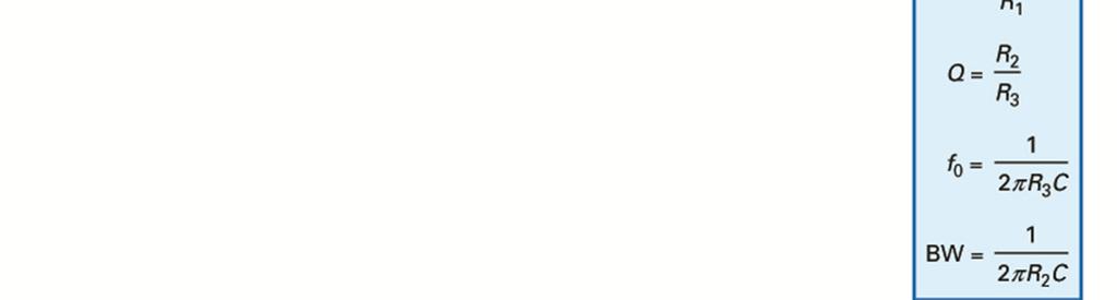
24 Tunable MFB bandpass ilter with constant bandwidth C 2R 1 R 1 v in C v out R 3 A v = -1 BW = 0 Q 0 = 2πC 1 2R 1 (R 1 R 3 ) Q = 0707 R 1 +R 3 R 3
25 Sallen-Key second-order notch ilter R/2 v in C R 2C C R R 2 1 Q = 05 As A 0 = v approaches 2 - A v 2πRC 2, this circuit R 2 v out R 1 A v = + 1 R 1 becomes impractical and may oscillate
26 The all-pass ilter Passes all requencies with no attenuation Controls the phase o the output signal Used as a phase or time-delay equalizer
27 First-order all-pass lag ilter R R v out v in A v = 1 R 1 0 = 2πRC C φ = -2 arctan 0
28 First-order all-pass lead ilter R R v out v in A v = -1 C 1 0 = 2πRC R 0 φ = 2 arctan
29 Linear phase shit Required to prevent distortion o digital signals Constant delay or all requencies in the passband Bessel design meets requirements but rollo might not be adequate Designers sometimes use a non-bessel design ollowed by an all-pass ilter to correct the phase shit
30 Biquadratic ilter Also called a TT ilter Uses three or our op amps Complex but oers lower component sensitivity and easier tuning Has simultaneous low-pass and bandpass outputs
31 Biquadratic stage
32 State-variable ilter Also called the KHN ilter Uses three or more op amps When a ourth op amp is used, it oers easy tuning because voltage gain, center requency, and Q are all independently tunable
33 State variable stage v in R R = 2πRC R HP output R R 2 R C A v = Q = R BP output R 2 R C LP output
Introduction (cont )
") Active Filter 1 Introduction Filters are circuits that are capable of passing signals within a band of frequencies while rejecting or blocking signals of frequencies outside this band. This property of
Active Filter 1 Introduction Filters are circuits that are capable of passing signals within a band of frequencies while rejecting or blocking signals of frequencies outside this band. This property of
Chapter 15: Active Filters
 Chapter 15: Active Filters 15.1: Basic filter Responses A filter is a circuit that passes certain frequencies and rejects or attenuates all others. The passband is the range of frequencies allowed to pass
Active Filters - Revisited
 Active Filters - Revisited Sources: Electronic Devices by Thomas L. Floyd. & Electronic Devices and Circuit Theory by Robert L. Boylestad, Louis Nashelsky Ideal and Practical Filters Ideal and Practical
Active Filter Design Techniques
 Active Filter Design Techniques 16.1 Introduction What is a filter? A filter is a device that passes electric signals at certain frequencies or frequency ranges while preventing the passage of others.
Operational Amplifiers
 Operational Amplifiers Continuing the discussion of Op Amps, the next step is filters. There are many different types of filters, including low pass, high pass and band pass. We will discuss each of the
An active filters means using amplifiers to improve the filter. An acive second-order RC low-pass filter still has two RC components in series.
 Active Filters An active filters means using amplifiers to improve the filter. An acive second-order low-pass filter still has two components in series. Hjω ( ) -------------------------- 2 = = ----------------------------------------------------------
Analog Design-filters
 Analog Design-filters Introduction and Motivation Filters are networks that process signals in a frequency-dependent manner. The basic concept of a filter can be explained by examining the frequency dependent
EXPERIMENT 1: Characteristics of Passive and Active Filters
 Kathmandu University Department of Electrical and Electronics Engineering ELECTRONICS AND ANALOG FILTER DESIGN LAB EXPERIMENT : Characteristics of Passive and Active Filters Objective: To understand the
Lecture 17 Date: Parallel Resonance Active and Passive Filters
 Lecture 17 Date: 09.10.2017 Parallel Resonance Active and Passive Filters Parallel Resonance At resonance: The voltage V as a function of frequency. At resonance, the parallel LC combination acts like
Filters and Tuned Amplifiers
 CHAPTER 6 Filters and Tuned Amplifiers Introduction 55 6. Filter Transmission, Types, and Specification 56 6. The Filter Transfer Function 60 6.7 Second-Order Active Filters Based on the Two-Integrator-Loop
Chapter 2. The Fundamentals of Electronics: A Review
 Chapter 2 The Fundamentals of Electronics: A Review Topics Covered 2-1: Gain, Attenuation, and Decibels 2-2: Tuned Circuits 2-3: Filters 2-4: Fourier Theory 2-1: Gain, Attenuation, and Decibels Most circuits
PHYS 536 Active Filters
 PHYS 536 Active Filters Introduction Active filters provide a sudden change in signal amplitude for a small change in frequency. Several filters can be used in series to increase the attenuation outside
PHYS225 Lecture 15. Electronic Circuits
 PHYS225 Lecture 15 Electronic Circuits Last lecture Difference amplifier Differential input; single output Good CMRR, accurate gain, moderate input impedance Instrumentation amplifier Differential input;
Chapter 19. Basic Filters
 Chapter 19 Basic Filters Objectives Analyze the operation of RC and RL lowpass filters Analyze the operation of RC and RL highpass filters Analyze the operation of band-pass filters Analyze the operation
Electric Circuit Theory
 Electric Circuit Theory Nam Ki Min nkmin@korea.ac.kr 010-9419-2320 Chapter 15 Active Filter Circuits Nam Ki Min nkmin@korea.ac.kr 010-9419-2320 Contents and Objectives 3 Chapter Contents 15.1 First-Order
CHAPTER 8 ANALOG FILTERS
 ANALOG FILTERS CHAPTER 8 ANALOG FILTERS SECTION 8.: INTRODUCTION 8. SECTION 8.2: THE TRANSFER FUNCTION 8.5 THE SPLANE 8.5 F O and Q 8.7 HIGHPASS FILTER 8.8 BANDPASS FILTER 8.9 BANDREJECT (NOTCH) FILTER
EEL 3923C. JD/ Module 3 Elementary Analog Filter Design. Prof. T. Nishida Fall 2010
 EEL 3923C JD/ Module 3 Elementary Analog Filter Design Prof. T. Nishida Fall 2010 Purpose Frequency selection Low pass, high pass, band pass, band stop, notch, etc. Applications II. Filter Fundamentals
Fundamentals of Active Filters
 Fundamentals of Active Filters This training module covers active filters. It introduces the three main filter optimizations, which include: Butterworth, Chebyshev and Bessel. The general transfer function
FYS3240 PC-based instrumentation and microcontrollers. Signal sampling. Spring 2015 Lecture #5
 FYS3240 PC-based instrumentation and microcontrollers Signal sampling Spring 2015 Lecture #5 Bekkeng, 29.1.2015 Content Aliasing Nyquist (Sampling) ADC Filtering Oversampling Triggering Analog Signal Information
EE301 ELECTRONIC CIRCUITS
 EE30 ELECTONIC CICUITS CHAPTE 5 : FILTES LECTUE : Engr. Muhammad Muizz Electrical Engineering Department Politeknik Kota Kinabalu, Sabah. 5. INTODUCTION Is a device that removes or filters unwanted signal.
Introduce cascaded first-order op-amp filters. Faculty of Electrical and Electronic Engineering
 Yıldız Technical University Cascaded FirstOrder Filters Introduce cascaded first-order op-amp filters Faculty of Electrical and Electronic Engineering Lesson Objectives Introduce cascaded filters Introduce
APPENDIX A to VOLUME A1 TIMS FILTER RESPONSES
 APPENDIX A to VOLUME A1 TIMS FILTER RESPONSES A2 TABLE OF CONTENTS... 5 Filter Specifications... 7 3 khz LPF (within the HEADPHONE AMPLIFIER)... 8 TUNEABLE LPF... 9 BASEBAND CHANNEL FILTERS - #2 Butterworth
Active Filter. Low pass filter High pass filter Band pass filter Band stop filter
 Active Filter Low pass filter High pass filter Band pass filter Band stop filter Active Low-Pass Filters Basic Low-Pass filter circuit At critical frequency, esistance capacitance X c ω c πf c So, critical
EKT 356 MICROWAVE COMMUNICATIONS CHAPTER 4: MICROWAVE FILTERS
 EKT 356 MICROWAVE COMMUNICATIONS CHAPTER 4: MICROWAVE FILTERS 1 INTRODUCTION What is a Microwave filter? linear 2-port network controls the frequency response at a certain point in a microwave system provides
3 Analog filters. 3.1 Analog filter characteristics
 Chapter 3, page 1 of 11 3 Analog filters This chapter deals with analog filters and the filter approximations of an ideal filter. The filter approximations that are considered are the classical analog
An active filter offers the following advantages over a passive filter:
 ACTIVE FILTERS An electric filter is often a frequency-selective circuit that passes a specified band of frequencies and blocks or attenuates signals of frequencies outside this band. Filters may be classified
A.C. FILTER NETWORKS. Learning Objectives
 C H A P T E 17 Learning Objectives Introduction Applications Different Types of Filters Octaves and Decades of Frequency Decibel System alue of 1 db Low-Pass C Filter Other Types of Low-Pass Filters Low-Pass
INTRODUCTION TO FILTER CIRCUITS
 INTRODUCTION TO FILTER CIRCUITS 1 2 Background: Filters may be classified as either digital or analog. Digital filters are implemented using a digital computer or special purpose digital hardware. Analog
Low Pass Filter Introduction
 Low Pass Filter Introduction Basically, an electrical filter is a circuit that can be designed to modify, reshape or reject all unwanted frequencies of an electrical signal and accept or pass only those
GENESYS 2003 Enterprise. Synthesis
 GENESYS 2003 Enterprise Synthesis Eagleware Corporation owns both the GENESYS software program suite and its documentation. No part of this publication may be produced, transmitted, transcribed, stored
Review of Filter Types
 ECE 440 FILTERS Review of Filters Filters are systems with amplitude and phase response that depends on frequency. Filters named by amplitude attenuation with relation to a transition or cutoff frequency.
NAPIER. University School of Engineering. Engineering Applications Module : SE32101 Active Filter Design 2 nd order Butterworth response
 NAPIER. University School of Engineering Engineering Applications Module : SE3101 nd order Butterworth response C1 4.7n 15V + R1 7.04k R 14.09k In C 4.7n OP1 ua741 + + - R3 10k -15V Out Sallen and key.
Filters occur so frequently in the instrumentation and
 FILTER Design CHAPTER 3 Filters occur so frequently in the instrumentation and communications industries that no book covering the field of RF circuit design could be complete without at least one chapter
Analog Filter and. Circuit Design Handbook. Arthur B. Williams. Singapore Sydney Toronto. Mc Graw Hill Education
 Analog Filter and Circuit Design Handbook Arthur B. Williams Mc Graw Hill Education New York Chicago San Francisco Athens London Madrid Mexico City Milan New Delhi Singapore Sydney Toronto Contents Preface
Downloaded from
 VI SEMESTER FINAL EXAMINATION 2003 Attempt ALL questions. Q. [1] [a] What is filter? Why it is required? Define half power points, rolloff and centre frequency. [3] [b] Plot the magnitude and phase response
Keywords: op amp filters, Sallen-Key filters, high pass filter, opamps, single op amp
 Maxim > Design Support > Technical Documents > Tutorials > Amplifier and Comparator Circuits > APP 738 Maxim > Design Support > Technical Documents > Tutorials > Audio Circuits > APP 738 Maxim > Design
FEBRUARY 1998 VOLUME VIII NUMBER 1. The LTC1562 is the first in a new family of tunable, DC-accurate, continuous-time
 LINEAR TECHNOLOGY FEBRUARY VOLUME VIII NUMBER IN THIS ISSUE COVER ARTICLE Universal Continuous-Time Filter Challenges Discrete Designs... Max Hauser Issue Highlights... LTC in the News... DESIGN FEATURES
Analog Lowpass Filter Specifications
 Analog Lowpass Filter Specifications Typical magnitude response analog lowpass filter may be given as indicated below H a ( j of an Copyright 005, S. K. Mitra Analog Lowpass Filter Specifications In the
An Application of Bandpass Filters. Jeff Crawford - K ZR October 15, 2016
 An Application of Bandpass Filters Jeff Crawford - K ZR October 15, 2016 1 Goals for this Discussion: Cover some general filter theory Apply this theory to an amateur radio need SO2R (Single Operator 2
EECS40 RLC Lab guide
 EECS40 RLC Lab guide Introduction Second-Order Circuits Second order circuits have both inductor and capacitor components, which produce one or more resonant frequencies, ω0. In general, a differential
A third-order active-r filter with feedforward input signal
 Sādhanā Vol. 28, Part 6, December 2003, pp. 1019 1026. Printed in India A third-order active-r filter with feedforward input signal G N SHINDE 1,PBPATIL 2 and P R MIRKUTE 1 1 Department of Electronics,
Lowpass Filters. Microwave Filter Design. Chp5. Lowpass Filters. Prof. Tzong-Lin Wu. Department of Electrical Engineering National Taiwan University
 Microwave Filter Design Chp5. Lowpass Filters Prof. Tzong-Lin Wu Department of Electrical Engineering National Taiwan University Lowpass Filters Design steps Select an appropriate lowpass filter prototype
Lecture 21 Frequency Response: Nov. 21, 2011
 Lecture 21 Frequency Response: Resonance, 2 nd Order Filters and Active Filters Nov. 21, 2011 Material from Textbook by Alexander & Sadiku and Electrical Engineering: Principles & Applications, A. R. Hambley
EE233 Autumn 2016 Electrical Engineering University of Washington. EE233 HW7 Solution. Nov. 16 th. Due Date: Nov. 23 rd
 EE233 HW7 Solution Nov. 16 th Due Date: Nov. 23 rd 1. Use a 500nF capacitor to design a low pass passive filter with a cutoff frequency of 50 krad/s. (a) Specify the cutoff frequency in hertz. fc c 50000
Analog Circuits and Systems
 Analog Circuits and Systems Prof. K Radhakrishna Rao Lecture 30: Automatic Tuning of Filters (PLL) and Review of Filter Design 1 Review Frequency Compensation 2 Review (contd.,) Switched Capacitor Filters
Analog Filters D R. T A R E K T U T U N J I P H I L A D E L P H I A U N I V E R S I T Y, J O R D A N
 Analog Filters D. T A E K T U T U N J I P H I L A D E L P H I A U N I V E S I T Y, J O D A N 2 0 4 Introduction Electrical filters are deigned to eliminate unwanted frequencies Filters can be classified
Physics 481 Experiment 1
 Physics 481 Experiment 1 LAST Name (print) FIRST Name (print) LINEAR CIRCUITS 1 Experiment 1 - Linear Circuits This experiment is designed for getting a hands-on experience with simple linear circuits.
ECE 203 LAB 2 PRACTICAL FILTER DESIGN & IMPLEMENTATION
 Version 1. 1 of 7 ECE 03 LAB PRACTICAL FILTER DESIGN & IMPLEMENTATION BEFORE YOU BEGIN PREREQUISITE LABS ECE 01 Labs ECE 0 Advanced MATLAB ECE 03 MATLAB Signals & Systems EXPECTED KNOWLEDGE Understanding
Chapter 12 RF and AF Filters
 Chapter 12 RF and AF Filters This chapter contains design information and examples of the most common filters used by radio amateurs. The initial sections describing basic concepts, lumped element filters
Analog Electronics. Lecture. Op-amp Circuits and Active Filters. Muhammad Amir Yousaf
 Analog Electronics Lecture Op-amp Circuits and Active Filters Muhammad Amir Yousaf Instrumentation Amplifiers An instrumentation amplifier (IA) amplifies the voltage difference between its terminals. It
Microwave Circuits Design. Microwave Filters. high pass
 Used to control the frequency response at a certain point in a microwave system by providing transmission at frequencies within the passband of the filter and attenuation in the stopband of the filter.
REALIZATION OF SOME NOVEL ACTIVE CIRCUITS SYNOPSIS
 REALIZATION OF SOME NOVEL ACTIVE CIRCUITS SYNOPSIS Filter is a generic term to describe a signal processing block. Filter circuits pass only a certain range of signal frequencies and block or attenuate
CHAPTER 14. Introduction to Frequency Selective Circuits
 CHAPTER 14 Introduction to Frequency Selective Circuits Frequency-selective circuits Varying source frequency on circuit voltages and currents. The result of this analysis is the frequency response of
Continuous-Time Analog Filters
 ENGR 4333/5333: Digital Signal Processing Continuous-Time Analog Filters Chapter 2 Dr. Mohamed Bingabr University of Central Oklahoma Outline Frequency Response of an LTIC System Signal Transmission through
Continuous- Time Active Filter Design
 Continuous- Time Active Filter Design T. Deliyannis Yichuang Sun J.K. Fidler CRC Press Boca Raton London New York Washington, D.C. Contents Chapter 1 Filter Fundamentals 1.1 Introduction 1 1.2 Filter Characterization
L 0R6 R1 C1. Introducing the MF10 A Versatile Monolithic Active Filter Building Block
 Introducing the MF10 A Versatile Monolithic Active Filter Building Block A unique alternative for active filter designs is now available with the introduction of the MF10 This new CMOS device can be used
SALLEN-KEY LOW-PASS FILTER DESIGN PROGRAM
 SALLEN-KEY LOW-PASS FILTER DESIGN PROGRAM By Bruce Trump and R. Mark Stitt (62) 746-7445 Although low-pass filters are vital in modern electronics, their design and verification can be tedious and time
OSCILLATORS. Introduction
 OSILLATOS Introduction Oscillators are essential components in nearly all branches o electrical engineering. Usually, it is desirable that they be tunable over a speciied requency range, one example being
TDA7000 for narrowband FM reception
 TDA7 for narrowband FM reception Author: Author: W.V. Dooremolen INTRODUCTION Today s cordless telephone sets make use of duplex communication with carrier frequencies of about.7mhz and 49MHz. In the base
Analog and Telecommunication Electronics
 Politecnico di Torino - ICT School Analog and Telecommunication Electronics E1 - Filters type and design» Filter taxonomy and parameters» Design flow and tools» FilterCAD example» Basic II order cells
Advanced Electronic Systems
 Advanced Electronic Systems Damien Prêle To cite this version: Damien Prêle. Advanced Electronic Systems. Master. Advanced Electronic Systems, Hanoi, Vietnam. 2016, pp.140. HAL Id: cel-00843641
Analog and Telecommunication Electronics
 Politecnico di Torino - ICT School Analog and Telecommunication Electronics E1 - Filters type and design» Filter taxonomy and parameters» Design flow and tools» FilterCAD example» Basic II order cells
Deliyannis, Theodore L. et al "Realization of First- and Second-Order Functions Using Opamps" Continuous-Time Active Filter Design Boca Raton: CRC
 Deliyannis, Theodore L. et al "Realization of First- and Second-Order Functions Using Opamps" Continuous-Time Active Filter Design Boca Raton: CRC Press LLC,999 Chapter 4 Realization of First- and Second-Order
University of Southern California
 University of Southern alifornia Ming Hsieh Department of Electrical Engineering EE 0L - Linear ircuits Homework Set #6 Due in class Thursday 9 April Problems 3.33 3.34 3.35 a and b only) The problems
Butterworth Active Bandpass Filter using Sallen-Key Topology
 Butterworth Active Bandpass Filter using Sallen-Key Topology Technical Report 5 Milwaukee School of Engineering ET-3100 Electronic Circuit Design Submitted By: Alex Kremnitzer Date: 05-11-2011 Date Performed:
Transactions on Engineering Sciences vol 3, 1993 WIT Press, ISSN
 Software for teaching design and analysis of analog and digital filters D. Baez-Lopez, E. Jimenez-Lopez, R. Alejos-Palomares, J.M. Ramirez Departamento de Ingenieria Electronica, Universidad de las Americas-
Back to. Communication Products Group. Technical Notes. Adjustment and Performance of Variable Equalizers
 Back to Communication Products Group Technical Notes 25T014 Adjustment and Performance of Variable Equalizers MITEQ TECHNICAL NOTE 25TO14 JUNE 1995 REV B ADJUSTMENT AND PERFORMANCE OF VARIABLE EQUALIZERS
Fourth-Order Butterworth Active Bandpass Filter Design for Single-Sided Magnetic Particle Imaging Scanner
 Fourth-Order Butterworth Active Bandpass Filter Design for Single-Sided Magnetic Particle Imaging Scanner A. A. Sadiq, N. B. Othman, M. M. Abdul Jamil, M. Youseffi, M. Denyer,3, W. N. Wan Zakaria 4, and
Thank you Carmina. Welcome all to our presentation of Direct Filter Synthesis for Customized Response
 Thank you Carmina. Welcome all to our presentation of Direct Filter Synthesis for Customized Response 1 This is just a brief review of our agenda, first we will review the Functions and types of filters
Project 2. Project 2: audio equalizer. Fig. 1: Kinter MA-170 stereo amplifier with bass and treble controls.
 Introduction Project 2 Project 2: audio equalizer This project aims to motivate our study o ilters by considering the design and implementation o an audio equalizer. An equalizer (EQ) modiies the requency
Part Numbering System
 Reactel Filters can satisfy a variety of filter requirements. These versatile units cover the broad frequency range of 2 khz to 5 GHz, and are available in either tubular or rectangular packages, connectorized
ECE 202 (Talavage) Exam #3
 Exam #3") ECE 202 (Talavage) Exam #3 23 November 2015 Name: INSTRUCTIONS This is a closed book, closed notes exam. The exam consists of 8 thematic problems (19 parts) worth a total of 100 points. No computers, cell
ECE 202 (Talavage) Exam #3 23 November 2015 Name: INSTRUCTIONS This is a closed book, closed notes exam. The exam consists of 8 thematic problems (19 parts) worth a total of 100 points. No computers, cell
1) Consider the circuit shown in figure below. Compute the output waveform for an input of 5kHz
 Consider the circuit shown in figure below. Compute the output waveform for an input of 5kHz") ) Consider the circuit shown in figure below. Compute the output waveform for an input of 5kHz Solution: a) Input is of constant amplitude of 2 V from 0 to 0. ms and 2 V from 0. ms to 0.2 ms. The output
) Consider the circuit shown in figure below. Compute the output waveform for an input of 5kHz Solution: a) Input is of constant amplitude of 2 V from 0 to 0. ms and 2 V from 0. ms to 0.2 ms. The output
FYS3240 PC-based instrumentation and microcontrollers. Signal sampling. Spring 2017 Lecture #5
 FYS3240 PC-based instrumentation and microcontrollers Signal sampling Spring 2017 Lecture #5 Bekkeng, 30.01.2017 Content Aliasing Sampling Analog to Digital Conversion (ADC) Filtering Oversampling Triggering
Philadelphia University Faculty of Engineering Communication and Electronics Engineering. Amplifier Circuits-III
 Module: Electronics II Module Number: 6503 Philadelphia University Faculty o Engineering Communication and Electronics Engineering Ampliier Circuits-III Operational Ampliiers (Op-Amps): An operational
Advanced Measurements
 Albaha University Faculty of Engineering Mechanical Engineering Department Lecture 9: Wheatstone Bridge and Filters Ossama Abouelatta o_abouelatta@yahoo.com Mechanical Engineering Department Faculty of
ELEC207 Linear Integrated Circuits
 University o Nizwa Faculty o Engineering and Architecture Electrical and omputer Engineering ELE07 Linear Integrated ircuits Week 8 Ate Abu alim Fall 05/06 0/5/05 FILTE A ilter is a device that passes
EELE503. Modern filter design. Filter Design - Introduction
 EELE503 Modern filter design Filter Design - Introduction A filter will modify the magnitude or phase of a signal to produce a desired frequency response or time response. One way to classify ideal filters
PART. MAX7421CUA 0 C to +70 C 8 µmax INPUT CLOCK
 19-181; Rev ; 11/ 5th-Order, Lowpass, General Description The MAX718 MAX75 5th-order, low-pass, switchedcapacitor filters (SCFs) operate from a single +5 (MAX718 MAX71) or +3 (MAX7 MAX75) supply. These
ISOlinear Architecture. Silicon Labs CMOS Isolator. Figure 1. ISOlinear Design Architecture. Table 1. Circuit Performance mv 0.
 ISOLATING ANALOG SIGNALS USING THE Si86XX CMOS ISOLATOR FAMILY. Introduction AN559 The ISOlinear reference design (Si86ISOLIN-KIT) provides galvanic isolation for analog signals over a frequency range
NOVEMBER 13, 1996 EE 4773/6773: LECTURE NO. 37 PAGE 1 of 5
 NOVEMBER 3, 996 EE 4773/6773: LECTURE NO. 37 PAGE of 5 Characteristics of Commonly Used Analog Filters - Butterworth Butterworth filters are maimally flat in the passband and stopband, giving monotonicity
Filter Approximation Concepts
 6 (ESS) Filter Approximation Concepts How do you translate filter specifications into a mathematical expression which can be synthesized? Approximation Techniques Why an ideal Brick Wall Filter can not
Thinking Outside the Band: Absorptive Filtering Matthew A. Morgan
 Thinking Outside the Band: Absorptive Filtering Matthew A. Morgan Introduction Today's high-requency radio system engineer has at his ingertips an encyclopedic body o work to draw upon or his iltering
Chapter 30 Inductance, Electromagnetic. Copyright 2009 Pearson Education, Inc.
 Chapter 30 Inductance, Electromagnetic Oscillations, and AC Circuits 30-7 AC Circuits with AC Source Resistors, capacitors, and inductors have different phase relationships between current and voltage
Kerwin, W.J. Passive Signal Processing The Electrical Engineering Handbook Ed. Richard C. Dorf Boca Raton: CRC Press LLC, 2000
 Kerwin, W.J. Passive Signal Processing The Electrical Engineering Handbook Ed. Richard C. Dorf Boca Raton: CRC Press LLC, 000 4 Passive Signal Processing William J. Kerwin University of Arizona 4. Introduction
UNIVERSITY OF NAIROBI
 UNIVERSITY OF NAIROBI COLLEGE OF ARCHITECTURE AND ENGINEERING SCHOOL OF ENGINEERING DEPARTMENT OF ELECTRICAL AND INFORMATION ENGINEERING PROJECT INDEX: 096 PROJECT TITLE: DESIGN OF A 50W POWER AMPLIFIER
Filter Notes. You may have memorized a formula for the voltage divider - if not, it is easily derived using Ohm's law, Vo Vi
 Filter Notes You may have memorized a formula for the voltage divider - if not, it is easily derived using Ohm's law, Vo Vi R2 R+ R2 If you recall the formula for capacitive reactance, the divider formula
NH 67, Karur Trichy Highways, Puliyur C.F, Karur District DEPARTMENT OF INFORMATION TECHNOLOGY DIGITAL SIGNAL PROCESSING UNIT 3
 NH 67, Karur Trichy Highways, Puliyur C.F, 639 114 Karur District DEPARTMENT OF INFORMATION TECHNOLOGY DIGITAL SIGNAL PROCESSING UNIT 3 IIR FILTER DESIGN Structure of IIR System design of Discrete time
Philadelphia University Faculty of Engineering Communication and Electronics Engineering. Amplifier Circuits-IV
 Module: Electronics II Module Number: 6503 Philadelphia University Faculty o Engineering Communication and Electronics Engineering Ampliier Circuits-IV Oscillators and Linear Digital IC's: Oscillators:
CHAPTER 6: ALTERNATING CURRENT
 CHAPTER 6: ALTERNATING CURRENT PSPM II 2005/2006 NO. 12(C) 12. (c) An ac generator with rms voltage 240 V is connected to a RC circuit. The rms current in the circuit is 1.5 A and leads the voltage by
Classic Filters. Figure 1 Butterworth Filter. Chebyshev
 Classic Filters There are 4 classic analogue filter types: Butterworth, Chebyshev, Elliptic and Bessel. There is no ideal filter; each filter is good in some areas but poor in others. Butterworth: Flattest
Transfer function: a mathematical description of network response characteristics.
 Microwave Filter Design Chp3. Basic Concept and Theories of Filters Prof. Tzong-Lin Wu Department of Electrical Engineering National Taiwan University Transfer Functions General Definitions Transfer function:
856 Feedback Networks: Theory and Circuit Applications. Butterworth MFM response, 767 Butterworth response, 767
 Index I/O transfer admittance, 448 N stage cascade, 732, 734 S-parameter characterization, 226 ω max, 204 π-type, 148 π-type network model, 137 c-parameter, 151, 153 c-parameter matrix, 154 g-parameter
LS404 HIGH PERFORMANCE QUAD OPERATIONAL AMPLIFIER
 HIGH PERORMANCE QUAD OPERATIONAL AMPLIIER SINGLE OR SPLIT SUPPLY OPERATION LOW POWER CONSUMPTION SHORT CIRCUIT PROTECTION LOW DISTORTION, LOW NOISE HIGH GAINBANDWIDTH PRODUCT HIGH CHANNEL SEPARATION DESCRIPTION
Electronics II. 3. measurement : Tuned circuits
 Electronics II. 3. measurement : Tuned circuits This laboratory session involves circuits which contain a double-t (or TT), a passive RC circuit: Figure 1. Double T passive RC circuit module The upper
Electrical Circuits II (ECE233b)
") Electrical ircuits II (EE33b) ariablefrequency Network Performance (Part 3) Anestis Dounavis The University of Western Ontario Faculty of Engineering Science Scaling Often the values of circuit parameters
Electrical ircuits II (EE33b) ariablefrequency Network Performance (Part 3) Anestis Dounavis The University of Western Ontario Faculty of Engineering Science Scaling Often the values of circuit parameters
EE 508 Lecture 18. Basic Biquadratic Active Filters. Second-order Bandpass Second-order Lowpass Effects of Op Amp on Filter Performance
 EE 58 Lecture 8 Basic ratic Active Filters Second-order Bandpass Second-order Lowpass Effects of Op Amp on Filter Performance eview from Last Time Standard LP to BS Transformation map = to = ± map = to
Frequency Response Analysis
 Frequency Response Analysis Continuous Time * M. J. Roberts - All Rights Reserved 2 Frequency Response * M. J. Roberts - All Rights Reserved 3 Lowpass Filter H( s) = ω c s + ω c H( jω ) = ω c jω + ω c
Audio Applications for Op-Amps, Part III By Bruce Carter Advanced Analog Products, Op Amp Applications Texas Instruments Incorporated
 Audio Applications for OpAmps, Part III By Bruce Carter Advanced Analog Products, Op Amp Applications Texas Instruments Incorporated This is the third in a series of articles on singlesupply audio circuits.
EXPERIMENT 8: LRC CIRCUITS
 EXPERIMENT 8: LRC CIRCUITS Equipment List S 1 BK Precision 4011 or 4011A 5 MHz Function Generator OS BK 2120B Dual Channel Oscilloscope V 1 BK 388B Multimeter L 1 Leeds & Northrup #1532 100 mh Inductor