Introduce cascaded first-order op-amp filters. Faculty of Electrical and Electronic Engineering
|
|
|
- Hugo Black
- 5 years ago
- Views:
Transcription
1 Yıldız Technical University Cascaded FirstOrder Filters Introduce cascaded first-order op-amp filters Faculty of Electrical and Electronic Engineering
2 Lesson Objectives Introduce cascaded filters Introduce bandpass filter characteristics Introduce second-order transfer functions 2
3 First-Order LPF and HPF 3

4 Cascaded Filter Input First-Order LPF Output Input First-Order HPF Output 4
5 Cascaded Filter 5

6 Bandpass Filter Characteristics 6
7 Transfer Function Second-Order Filter Standard Form: 7

8 Cascaded Bandpass Filters 8
9 Question Is it possible to form a cascaded band-reject filter? 9
10 Summary Cascaded Filters Bandpass Transfer Functions 10
11 Second-Order Transfer Functions Introduce second-order filter transfer functions
12 Lesson Objectives Introduce second-order filter transfer functions Examine features of transfer functions 12
13 Filter Transfer Function Ratio of output voltage to input voltage as a function of frequency For any frequency, the transfer function is a complex number that indicates how the filter modifies the magnitude and phase of the input to produce the output 13
14 First-Order Low-Pass Filter 14
15 Second-Order Low-Pass Filter 15
16 Effect of Quality Factor (Q) 16
17 High-Pass Filters 17
18 Band-Pass Filters 18
19 Butterworth and Chebyshev Types of transfer functions For second-order filters, the type is determined by the Q value Butterworth (Maximally Flat) Chebyshev 19
20 Chebyshev Filters 20
21 Butterworth Filters 21
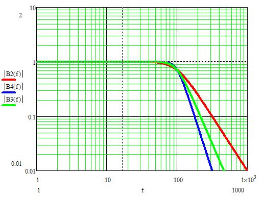
22 Fourth-Order Butterworth vs. Chebyshev 22
23 Summary Introduced second-order transfer functions Examined features of transfer functions 23
24 Second-Order Transfer Functions Introduce second-order filter transfer functions Faculty of Electrical and Electronic Engineering
25 Lesson Objectives Introduce second-order filter transfer functions Examine features of transfer functions 25
26 Filter Transfer Function Ratio of output voltage to input voltage as a function of frequency For any frequency, the transfer function is a complex number that indicates how the filter modifies the magnitude and phase of the input to produce the output 26

27 First-Order Low-Pass Filter 27
28 Second-Order Low-Pass Filter 28

29 Effect of Quality Factor (Q) 29

30 High-Pass Filters 30

31 Band-Pass Filters 31
32 Butterworth and Chebyshev Types of transfer functions For second-order filters, the type is determined by the Q value Butterworth (Maximally Flat) Chebyshev 32
33 Chebyshev Filters 33
34 Butterworth Filters 34
35 Fourth-Order Butterworth vs. Chebyshev 35
36 Summary Introduced second-order transfer functions Examined features of transfer functions 36
37 Second-Order Filter Circuits Introduce second-order Sallen-Key filter circuits
38 Lesson Objectives Introduce second-order filter circuits Design second-order filters 38
39 Sallen-Key Low-Pass Filter V i V o 39
40 Lowpass Design Equations Special Case 1 (K = 1, Solve for C s) Special Case 2 (K = 1, Solve for R s) Special Case 3 (R s equal and C s equal) Can simplify with R 1 and R 2 are interchangeable 40
41 Sallen-Key Highpass Filter V i V o 41
42 Highpass Design Equations Special Case 1 (K = 1, C 1 = C 2 = C) Special Case 2 (R s equal and C s equal) 42
43 Sallen-Key Bandpass Filter V i V o 43
44 Bandpass Design Equations Special Case (R s equal and C s equal) 44
45 Notch Filters 45
46 Example Design Butterworth 2 nd Order LPF Special Case 1 (K = 1, Solve for C s) Can simplify with 46
47 Example Design 47
48 Summary Introduced second-order filter circuits Designed a second-order lowpass filter 48
49 Filtering Demonstration Dr. İbrahim Beklan Küçükdemiral Department of Control and Automation Engineering Demonstrate filtering of signals
50 Lesson Objectives Examine frequency spectra of signals Demonstrate filtering by a second-order filter circuit 50
51 Spectrum of Sine Wave 51
52 Spectrum of Sum of Two Sine Waves 52
53 Spectrum of Square Wave 53
54 Spectrum of Square Wave 54
55 Relaxation Oscillator 55
56 Measurements 1kHz Square Wave V o Relaxation Oscillator f 0 = 1kHz Q=5 Sallen-Key BPF 56
57 Total Harmonic Distortion (THD) 57
58 Summary Introduced frequency spectra Examined physical circuit filtering performance 58
Lecture 17 Date: Parallel Resonance Active and Passive Filters
 Lecture 17 Date: 09.10.2017 Parallel Resonance Active and Passive Filters Parallel Resonance At resonance: The voltage V as a function of frequency. At resonance, the parallel LC combination acts like
Chapter 15: Active Filters
 Chapter 15: Active Filters 15.1: Basic filter Responses A filter is a circuit that passes certain frequencies and rejects or attenuates all others. The passband is the range of frequencies allowed to pass
Active Filters - Revisited
 Active Filters - Revisited Sources: Electronic Devices by Thomas L. Floyd. & Electronic Devices and Circuit Theory by Robert L. Boylestad, Louis Nashelsky Ideal and Practical Filters Ideal and Practical
Active Filter Design Techniques
 Active Filter Design Techniques 16.1 Introduction What is a filter? A filter is a device that passes electric signals at certain frequencies or frequency ranges while preventing the passage of others.
Electronic PRINCIPLES
 MALVINO & BATES Electronic PRINCIPLES SEVENTH EDITION Chapter 21 Active Filters Topics Covered in Chapter 21 Ideal responses Approximate responses Passive ilters First-order stages VCVS unity-gain second-order
EXPERIMENT 1: Characteristics of Passive and Active Filters
 Kathmandu University Department of Electrical and Electronics Engineering ELECTRONICS AND ANALOG FILTER DESIGN LAB EXPERIMENT : Characteristics of Passive and Active Filters Objective: To understand the
APPENDIX A to VOLUME A1 TIMS FILTER RESPONSES
 APPENDIX A to VOLUME A1 TIMS FILTER RESPONSES A2 TABLE OF CONTENTS... 5 Filter Specifications... 7 3 khz LPF (within the HEADPHONE AMPLIFIER)... 8 TUNEABLE LPF... 9 BASEBAND CHANNEL FILTERS - #2 Butterworth
PHYS225 Lecture 15. Electronic Circuits
 PHYS225 Lecture 15 Electronic Circuits Last lecture Difference amplifier Differential input; single output Good CMRR, accurate gain, moderate input impedance Instrumentation amplifier Differential input;
Low Pass Filter Introduction
 Low Pass Filter Introduction Basically, an electrical filter is a circuit that can be designed to modify, reshape or reject all unwanted frequencies of an electrical signal and accept or pass only those
Active Filter. Low pass filter High pass filter Band pass filter Band stop filter
 Active Filter Low pass filter High pass filter Band pass filter Band stop filter Active Low-Pass Filters Basic Low-Pass filter circuit At critical frequency, esistance capacitance X c ω c πf c So, critical
Electric Circuit Theory
 Electric Circuit Theory Nam Ki Min nkmin@korea.ac.kr 010-9419-2320 Chapter 15 Active Filter Circuits Nam Ki Min nkmin@korea.ac.kr 010-9419-2320 Contents and Objectives 3 Chapter Contents 15.1 First-Order
LECTURER NOTE SMJE3163 DSP
 LECTURER NOTE SMJE363 DSP (04/05-) ------------------------------------------------------------------------- Week3 IIR Filter Design -------------------------------------------------------------------------
Fourth-Order Butterworth Active Bandpass Filter Design for Single-Sided Magnetic Particle Imaging Scanner
 Fourth-Order Butterworth Active Bandpass Filter Design for Single-Sided Magnetic Particle Imaging Scanner A. A. Sadiq, N. B. Othman, M. M. Abdul Jamil, M. Youseffi, M. Denyer,3, W. N. Wan Zakaria 4, and
Butterworth Active Bandpass Filter using Sallen-Key Topology
 Butterworth Active Bandpass Filter using Sallen-Key Topology Technical Report 5 Milwaukee School of Engineering ET-3100 Electronic Circuit Design Submitted By: Alex Kremnitzer Date: 05-11-2011 Date Performed:
 UNIT IV FIR FILTER DESIGN 1. How phase distortion and delay distortion are introduced? The phase distortion is introduced when the phase characteristics of a filter is nonlinear within the desired frequency
INTRODUCTION TO FILTER CIRCUITS
 INTRODUCTION TO FILTER CIRCUITS 1 2 Background: Filters may be classified as either digital or analog. Digital filters are implemented using a digital computer or special purpose digital hardware. Analog
ECE 440L. Experiment 1: Signals and Noise (1 week)
") ECE 440L Experiment 1: Signals and Noise (1 week) I. OBJECTIVES Upon completion of this experiment, you should be able to: 1. Use the signal generators and filters in the lab to generate and filter noise
ECE 440L Experiment 1: Signals and Noise (1 week) I. OBJECTIVES Upon completion of this experiment, you should be able to: 1. Use the signal generators and filters in the lab to generate and filter noise
Analog Circuits and Systems
 Analog Circuits and Systems Prof. K Radhakrishna Rao Lecture 30: Automatic Tuning of Filters (PLL) and Review of Filter Design 1 Review Frequency Compensation 2 Review (contd.,) Switched Capacitor Filters
An active filter offers the following advantages over a passive filter:
 ACTIVE FILTERS An electric filter is often a frequency-selective circuit that passes a specified band of frequencies and blocks or attenuates signals of frequencies outside this band. Filters may be classified
Image acquisition. Midterm Review. Digitization, line of image. Digitization, whole image. Geometric transformations. Interpolation 10/26/2016
 Image acquisition Midterm Review Image Processing CSE 166 Lecture 10 2 Digitization, line of image Digitization, whole image 3 4 Geometric transformations Interpolation CSE 166 Transpose these matrices
Designing Information Devices and Systems II Fall 2018 Elad Alon and Miki Lustig Homework 4
 EECS 16B Designing Information Devices and Systems II Fall 2018 Elad Alon and Miki Lustig Homework 4 This homework is solely for your own practice. However, everything on it is in scope for midterm 1,
Downloaded from
 VI SEMESTER FINAL EXAMINATION 2003 Attempt ALL questions. Q. [1] [a] What is filter? Why it is required? Define half power points, rolloff and centre frequency. [3] [b] Plot the magnitude and phase response
An Application of Bandpass Filters. Jeff Crawford - K ZR October 15, 2016
 An Application of Bandpass Filters Jeff Crawford - K ZR October 15, 2016 1 Goals for this Discussion: Cover some general filter theory Apply this theory to an amateur radio need SO2R (Single Operator 2
Part Numbering System
 Reactel Filters can satisfy a variety of filter requirements. These versatile units cover the broad frequency range of 2 khz to 5 GHz, and are available in either tubular or rectangular packages, connectorized
ISOlinear Architecture. Silicon Labs CMOS Isolator. Figure 1. ISOlinear Design Architecture. Table 1. Circuit Performance mv 0.
 ISOLATING ANALOG SIGNALS USING THE Si86XX CMOS ISOLATOR FAMILY. Introduction AN559 The ISOlinear reference design (Si86ISOLIN-KIT) provides galvanic isolation for analog signals over a frequency range
FEBRUARY 1998 VOLUME VIII NUMBER 1. The LTC1562 is the first in a new family of tunable, DC-accurate, continuous-time
 LINEAR TECHNOLOGY FEBRUARY VOLUME VIII NUMBER IN THIS ISSUE COVER ARTICLE Universal Continuous-Time Filter Challenges Discrete Designs... Max Hauser Issue Highlights... LTC in the News... DESIGN FEATURES
PART. MAX7421CUA 0 C to +70 C 8 µmax INPUT CLOCK
 19-181; Rev ; 11/ 5th-Order, Lowpass, General Description The MAX718 MAX75 5th-order, low-pass, switchedcapacitor filters (SCFs) operate from a single +5 (MAX718 MAX71) or +3 (MAX7 MAX75) supply. These
UNIVERSITY OF NAIROBI
 UNIVERSITY OF NAIROBI COLLEGE OF ARCHITECTURE AND ENGINEERING SCHOOL OF ENGINEERING DEPARTMENT OF ELECTRICAL AND INFORMATION ENGINEERING PROJECT INDEX: 096 PROJECT TITLE: DESIGN OF A 50W POWER AMPLIFIER
APPLICATION NOTE 6206 SIMPLE, EFFECTIVE METHOD AND CIRCUIT TO MEASURE VERY-LOW 1/F VOLTAGE REFERENCE NOISE (< 1ΜV P-P, 0.
 Keywords: 0.1 to 10 Hz noise of voltage reference, low frequency noise or flicker noise of voltage reference, ultra low noise measurement of voltage reference APPLICATION NOTE 606 SIMPLE, EFFECTIVE METHOD
Review of Filter Types
 ECE 440 FILTERS Review of Filters Filters are systems with amplitude and phase response that depends on frequency. Filters named by amplitude attenuation with relation to a transition or cutoff frequency.
Analog Design-filters
 Analog Design-filters Introduction and Motivation Filters are networks that process signals in a frequency-dependent manner. The basic concept of a filter can be explained by examining the frequency dependent
EC0206 LINEAR INTEGRATED CIRCUITS
 SRM UNIVERSITY FACULTY OF ENGINEERING AND TECHNOLOGY SCHOOL OF ELECTRONICS AND ELECTRICAL ENGINEERING DEPARTMENT OF ECE COURSE PLAN Course Code : EC0206 Course Title : Linear Integrated Circuits Semester
EELE503. Modern filter design. Filter Design - Introduction
 EELE503 Modern filter design Filter Design - Introduction A filter will modify the magnitude or phase of a signal to produce a desired frequency response or time response. One way to classify ideal filters
 1 2 B.E./B.Tech. DEGREE EXAMINATION, NOVEMBER/DECEMBER 2010 Fourth Semester Electrical and Electronics Engineering EE 2254 LINEAR INTEGRATED CIRCUITS AND APPLICATIONS (Common to Instrumentation and Control
NAPIER. University School of Engineering. Engineering Applications Module : SE32101 Active Filter Design 2 nd order Butterworth response
 NAPIER. University School of Engineering Engineering Applications Module : SE3101 nd order Butterworth response C1 4.7n 15V + R1 7.04k R 14.09k In C 4.7n OP1 ua741 + + - R3 10k -15V Out Sallen and key.
ECE 202 (Talavage) Exam #3
 Exam #3") ECE 202 (Talavage) Exam #3 23 November 2015 Name: INSTRUCTIONS This is a closed book, closed notes exam. The exam consists of 8 thematic problems (19 parts) worth a total of 100 points. No computers, cell
ECE 202 (Talavage) Exam #3 23 November 2015 Name: INSTRUCTIONS This is a closed book, closed notes exam. The exam consists of 8 thematic problems (19 parts) worth a total of 100 points. No computers, cell
 VALLIAMMAI ENGINEERING COLLEGE SRM Nagar, Kattankulathur 603 203. DEPARTMENT OF ELECTRONICS & COMMUNICATION ENGINEERING QUESTION BANK SUBJECT : EC6404 LINEAR INTEGRATED CIRCUITS SEM / YEAR: IV / II year
Oscillator Principles
 Oscillators Introduction Oscillators are circuits that generates a repetitive waveform of fixed amplitude and frequency without any external input signal. The function of an oscillator is to generate alternating
Designing Filters Using the NI LabVIEW Digital Filter Design Toolkit
 Application Note 097 Designing Filters Using the NI LabVIEW Digital Filter Design Toolkit Introduction The importance of digital filters is well established. Digital filters, and more generally digital
Lab 10: Oscillators (version 1.1)
") Lab 10: Oscillators (version 1.1) WARNING: Use electrical test equipment with care! Always double-check connections before applying power. Look for short circuits, which can quickly destroy expensive equipment.
Lab 10: Oscillators (version 1.1) WARNING: Use electrical test equipment with care! Always double-check connections before applying power. Look for short circuits, which can quickly destroy expensive equipment.
Shock sensor PKGS series Application manual of peripheral circuit Feb. 3, 2003 Example circuit for charge sensitivity type shock sensor.
 Example circuit for charge sensitivity type shock sensor. In this manual, it is explained the procedure how to calculate characteristics of the circuit for charge sensitivity type shock sensor, for example
Biosignal filtering and artifact rejection. Biosignal processing I, S Autumn 2017
 Biosignal filtering and artifact rejection Biosignal processing I, 52273S Autumn 207 Motivation ) Artifact removal power line non-stationarity due to baseline variation muscle or eye movement artifacts
ANALOG SYNTHESIZER WITH AR ENVELOPING
 ANALOG SYNTHESIZER WITH AR ENVELOPING EC412 MAY 5, 2013 CHRISTOPHER WOODALL CWOODALL@BU.EDU BENJAMIN HAVEY BENHAVEY@BU.EDU 1. Introduction Building an analog audio synthesizer is an exercise in low speed
Introduction (cont )
") Active Filter 1 Introduction Filters are circuits that are capable of passing signals within a band of frequencies while rejecting or blocking signals of frequencies outside this band. This property of
Active Filter 1 Introduction Filters are circuits that are capable of passing signals within a band of frequencies while rejecting or blocking signals of frequencies outside this band. This property of
Digital Signal Processing
 Digital Signal Processing System Analysis and Design Paulo S. R. Diniz Eduardo A. B. da Silva and Sergio L. Netto Federal University of Rio de Janeiro CAMBRIDGE UNIVERSITY PRESS Preface page xv Introduction
EC0206 Linear Integrated Circuits Fourth Semester, (even semester)
") COURSE HANDOUT Course (catalog) description SRM University Faculty of Engineering and Technology Department of Electronics and Communication Engineering EC0206 Linear Integrated Circuits Fourth Semester,
COURSE HANDOUT Course (catalog) description SRM University Faculty of Engineering and Technology Department of Electronics and Communication Engineering EC0206 Linear Integrated Circuits Fourth Semester,
EE247 Lecture 2. Butterworth Chebyshev I Chebyshev II Elliptic Bessel Group delay comparison example. EECS 247 Lecture 2: Filters
 EE247 Lecture 2 Material covered today: Nomenclature Filter specifications Quality factor Frequency characteristics Group delay Filter types Butterworth Chebyshev I Chebyshev II Elliptic Bessel Group delay
Analog Lowpass Filter Specifications
 Analog Lowpass Filter Specifications Typical magnitude response analog lowpass filter may be given as indicated below H a ( j of an Copyright 005, S. K. Mitra Analog Lowpass Filter Specifications In the
Analog Circuits Prof. Jayanta Mukherjee Department of Electrical Engineering Indian Institute of Technology - Bombay. Week 05 Module 07 Tutorial No 06
 Analog Circuits Prof. Jayanta Mukherjee Department of Electrical Engineering Indian Institute of Technology - Bombay Week 05 Module 07 Tutorial No 06 Welcome back to next tutorial video, last in last tutorial
P I M. Low PIM, High-Power Filter Solutions for Monitoring Broadband Emissions. Features: Broadband PIM Monitoring. General Concept for Low PIM ATE
 Features: Patent pending solution enables monitoring of PIM (Passive IM) up to 13 GHz, with high-power capabilities Near end monitoring: carriers are rejected -90 db by the notch filter and travel through
PART. MAX7401CSA 0 C to +70 C 8 SO MAX7405EPA MAX7401ESA MAX7405CSA MAX7405CPA MAX7405ESA V SUPPLY CLOCK
 19-4788; Rev 1; 6/99 8th-Order, Lowpass, Bessel, General Description The / 8th-order, lowpass, Bessel, switched-capacitor filters (SCFs) operate from a single +5 () or +3 () supply. These devices draw
Digital Filtering: Realization
 Digital Filtering: Realization Digital Filtering: Matlab Implementation: 3-tap (2 nd order) IIR filter 1 Transfer Function Differential Equation: z- Transform: Transfer Function: 2 Example: Transfer Function
Filters and Tuned Amplifiers
 CHAPTER 6 Filters and Tuned Amplifiers Introduction 55 6. Filter Transmission, Types, and Specification 56 6. The Filter Transfer Function 60 6.7 Second-Order Active Filters Based on the Two-Integrator-Loop
EE247 - Lecture 2 Filters. EECS 247 Lecture 2: Filters 2005 H.K. Page 1. Administrative. Office hours for H.K. changed to:
 EE247 - Lecture 2 Filters Material covered today: Nomenclature Filter specifications Quality factor Frequency characteristics Group delay Filter types Butterworth Chebyshev I Chebyshev II Elliptic Bessel
Electrical & Computer Engineering Technology
 Electrical & Computer Engineering Technology EET 419C Digital Signal Processing Laboratory Experiments by Masood Ejaz Experiment # 1 Quantization of Analog Signals and Calculation of Quantized noise Objective:
UNIT-II MYcsvtu Notes agk
 UNIT-II agk UNIT II Infinite Impulse Response Filter design (IIR): Analog & Digital Frequency transformation. Designing by impulse invariance & Bilinear method. Butterworth and Chebyshev Design Method.
R (a) Explain characteristics and limitations of op-amp comparators. (b) Explain operation of free running Multivibrator using op-amp.
 Explain characteristics and limitations of op-amp comparators. (b) Explain operation of free running Multivibrator using op-amp.") Set No: 1 1. (a) Draw the equivalent circuits of emitter coupled differential amplifier from which calculate Ad. (b) Draw the block diagram of four stage cascaded amplifier. Explain the function of each
Set No: 1 1. (a) Draw the equivalent circuits of emitter coupled differential amplifier from which calculate Ad. (b) Draw the block diagram of four stage cascaded amplifier. Explain the function of each
Analog Filters D R. T A R E K T U T U N J I P H I L A D E L P H I A U N I V E R S I T Y, J O R D A N
 Analog Filters D. T A E K T U T U N J I P H I L A D E L P H I A U N I V E S I T Y, J O D A N 2 0 4 Introduction Electrical filters are deigned to eliminate unwanted frequencies Filters can be classified
ME 365 EXPERIMENT 7 SIGNAL CONDITIONING AND LOADING
 ME 365 EXPERIMENT 7 SIGNAL CONDITIONING AND LOADING Objectives: To familiarize the student with the concepts of signal conditioning. At the end of the lab, the student should be able to: Understand the
Receiver Architecture
 Receiver Architecture Receiver basics Channel selection why not at RF? BPF first or LNA first? Direct digitization of RF signal Receiver architectures Sub-sampling receiver noise problem Heterodyne receiver
Fundamentals of Active Filters
 Fundamentals of Active Filters This training module covers active filters. It introduces the three main filter optimizations, which include: Butterworth, Chebyshev and Bessel. The general transfer function
The University of Texas at Austin Dept. of Electrical and Computer Engineering Midterm #2
 The University of Texas at Austin Dept. of Electrical and Computer Engineering Midterm #2 Date: November 18, 2010 Course: EE 313 Evans Name: Last, First The exam is scheduled to last 75 minutes. Open books
Problem Point Value Your score Topic 1 28 Filter Analysis 2 24 Filter Implementation 3 24 Filter Design 4 24 Potpourri Total 100
 The University of Texas at Austin Dept. of Electrical and Computer Engineering Midterm #1 Date: March 8, 2013 Course: EE 445S Evans Name: Last, First The exam is scheduled to last 50 minutes. Open books
Thursday, 1/23/19 Automatic Gain Control As previously shown, 1 0 is a nonlinear system that produces a limit cycle with a distorted sinusoid for
 Thursday, 1/23/19 Automatic Gain Control As previously shown, 1 0 is a nonlinear system that produces a limit cycle with a distorted sinusoid for x(t), which is not a very good sinusoidal oscillator. A
TABEL OF CONTENTS CHAPTER TITLE PAGE ABSTRAKT TABLE OF CONTENTS LIST OF TABLES LIST OF FIGURES LIST OF SYMBOLS
 v TABEL OF CONTENTS CHAPTER TITLE PAGE TITLE ABSTRACT ABSTRAKT TABLE OF CONTENTS LIST OF TABLES LIST OF FIGURES LIST OF SYMBOLS ii iii iv v ix x xiv 1 INTRODUCTION 1.1 Introduction 1 1.2 Objective 4 1.3
New Proposed Algorithms for nth Order Butterworth Active Filter Computer-Aided Design
 New Proposed Algorithms for nth Order Butterworth Active Filter Computer-Aided Design Information and Communication Department, Al-Khwarizmi Engineering College Baghdad University,Jaderia,Baghdad, Iraq.
Continuous- Time Active Filter Design
 Continuous- Time Active Filter Design T. Deliyannis Yichuang Sun J.K. Fidler CRC Press Boca Raton London New York Washington, D.C. Contents Chapter 1 Filter Fundamentals 1.1 Introduction 1 1.2 Filter Characterization
The New England Radio Discussion Society electronics course (Phase 4, cont d) The versatile op-amp
 The versatile op-amp") The New England Radio Discussion Society electronics course (Phase 4, cont d) The versatile op-amp AI2Q March 2017 We now recognize the symbol for an op-amp that s most often used in overall schematic
The New England Radio Discussion Society electronics course (Phase 4, cont d) The versatile op-amp AI2Q March 2017 We now recognize the symbol for an op-amp that s most often used in overall schematic
Analog Filter and. Circuit Design Handbook. Arthur B. Williams. Singapore Sydney Toronto. Mc Graw Hill Education
 Analog Filter and Circuit Design Handbook Arthur B. Williams Mc Graw Hill Education New York Chicago San Francisco Athens London Madrid Mexico City Milan New Delhi Singapore Sydney Toronto Contents Preface
Real and Complex Modulation
 Real and Complex Modulation TIPL 4708 Presented by Matt Guibord Prepared by Matt Guibord 1 What is modulation? Modulation is the act of changing a carrier signal s properties (amplitude, phase, frequency)
Final Exam Solutions June 14, 2006
 Name or 6-Digit Code: PSU Student ID Number: Final Exam Solutions June 14, 2006 ECE 223: Signals & Systems II Dr. McNames Keep your exam flat during the entire exam. If you have to leave the exam temporarily,
An active filters means using amplifiers to improve the filter. An acive second-order RC low-pass filter still has two RC components in series.
 Active Filters An active filters means using amplifiers to improve the filter. An acive second-order low-pass filter still has two components in series. Hjω ( ) -------------------------- 2 = = ----------------------------------------------------------
Analog Electronics. Lecture. Op-amp Circuits and Active Filters. Muhammad Amir Yousaf
 Analog Electronics Lecture Op-amp Circuits and Active Filters Muhammad Amir Yousaf Instrumentation Amplifiers An instrumentation amplifier (IA) amplifies the voltage difference between its terminals. It
EKT 356 MICROWAVE COMMUNICATIONS CHAPTER 4: MICROWAVE FILTERS
 EKT 356 MICROWAVE COMMUNICATIONS CHAPTER 4: MICROWAVE FILTERS 1 INTRODUCTION What is a Microwave filter? linear 2-port network controls the frequency response at a certain point in a microwave system provides
UNIT II IIR FILTER DESIGN
 UNIT II IIR FILTER DESIGN Structures of IIR Analog filter design Discrete time IIR filter from analog filter IIR filter design by Impulse Invariance, Bilinear transformation Approximation of derivatives
Interactive Tone Generator with Capacitive Touch. Corey Cleveland and Eric Ponce. Project Proposal
 Interactive Tone Generator with Capacitive Touch Corey Cleveland and Eric Ponce Project Proposal Overview Capacitance is defined as the ability for an object to store charge. All objects have this ability,
Digital Processing of Continuous-Time Signals
 Chapter 4 Digital Processing of Continuous-Time Signals 清大電機系林嘉文 cwlin@ee.nthu.edu.tw 03-5731152 Original PowerPoint slides prepared by S. K. Mitra 4-1-1 Digital Processing of Continuous-Time Signals Digital
ECE 4670 Spring 2014 Lab 1 Linear System Characteristics
 ECE 4670 Spring 2014 Lab 1 Linear System Characteristics 1 Linear System Characteristics The first part of this experiment will serve as an introduction to the use of the spectrum analyzer in making absolute
PART MAX7427EUA MAX7426CPA MAX7427CPA TOP VIEW. Maxim Integrated Products 1
 19-171; Rev ; 4/ 5th-Order, Lowpass, Elliptic, General Description The 5th-order, lowpass, elliptic, switched-capacitor filters (SCFs) operate from a single +5 (MAX7426) or +3 (MAX7427) supply. The devices
Differential Amplifiers
 Differential Amplifiers Benefits of Differential Signal Processing The Benefits Become Apparent when Trying to get the Most Speed and/or Resolution out of a Design Avoid Grounding/Return Noise Problems
TDI2131 Digital Image Processing
 TDI131 Digital Image Processing Frequency Domain Filtering Lecture 6 John See Faculty of Information Technology Multimedia University Some portions of content adapted from Zhu Liu, AT&T Labs. Most figures
Motif Filters. Custom Filter Types... 20
 Motif Filters Contents Motif Filters Getting Started... 2 Output Filters... 5 Output Filters - Preset High Pass... 5 Output Filters - Preset LowPass... 7 Output Filters - Custom... 9 Custom Filter Types...
Digital Processing of
 Chapter 4 Digital Processing of Continuous-Time Signals 清大電機系林嘉文 cwlin@ee.nthu.edu.tw 03-5731152 Original PowerPoint slides prepared by S. K. Mitra 4-1-1 Digital Processing of Continuous-Time Signals Digital
Friday, 1/27/17 Constraints on A(jω)
") Friday, 1/27/17 Constraints on A(jω) The simplest electronic oscillators are op amp based, and A(jω) is typically a simple op amp fixed gain amplifier, such as the negative gain and positive gain amplifiers
Friday, 1/27/17 Constraints on A(jω) The simplest electronic oscillators are op amp based, and A(jω) is typically a simple op amp fixed gain amplifier, such as the negative gain and positive gain amplifiers
Part I - Amplitude Modulation
 EE/CME 392 Laboratory 1-1 Part I - Amplitude Modulation Safety: In this lab, voltages are less than 15 volts and this is not normally dangerous to humans. However, you should assemble or modify a circuit
11. Chapter: Amplitude stabilization of the harmonic oscillator
 Punčochář, Mohylová: TELO, Chapter 10 1 11. Chapter: Amplitude stabilization of the harmonic oscillator Time of study: 3 hours Goals: the student should be able to define basic principles of oscillator
Definitions. Spectrum Analyzer
 SIGNAL ANALYZERS Spectrum Analyzer Definitions A spectrum analyzer measures the magnitude of an input signal versus frequency within the full frequency range of the instrument. The primary use is to measure
University of Southern California
 University of Southern alifornia Ming Hsieh Department of Electrical Engineering EE 0L - Linear ircuits Homework Set #6 Due in class Thursday 9 April Problems 3.33 3.34 3.35 a and b only) The problems
Moku:Lab. Specifications INSTRUMENTS. Moku:Lab, rev
 Moku:Lab L I Q U I D INSTRUMENTS Specifications Moku:Lab, rev. 2018.1 Table of Contents Hardware 4 Specifications 4 Analog I/O 4 External trigger input 4 Clock reference 5 General characteristics 5 General
Designing Information Devices and Systems II Fall 2018 Elad Alon and Miki Lustig Homework 4
 EECS 6B Designing Information Devices and Systems II Fall 208 Elad Alon and Miki Lustig Homework 4 This homework is solely for your own practice. However, everything on it is in scope for midterm, and
Signals and Filtering
 FILTERING OBJECTIVES The objectives of this lecture are to: Introduce signal filtering concepts Introduce filter performance criteria Introduce Finite Impulse Response (FIR) filters Introduce Infinite
Signals and Systems Lecture 9 Communication Systems Frequency-Division Multiplexing and Frequency Modulation (FM)
") Signals and Systems Lecture 9 Communication Systems Frequency-Division Multiplexing and Frequency Modulation (FM) April 11, 2008 Today s Topics 1. Frequency-division multiplexing 2. Frequency modulation
Signals and Systems Lecture 9 Communication Systems Frequency-Division Multiplexing and Frequency Modulation (FM) April 11, 2008 Today s Topics 1. Frequency-division multiplexing 2. Frequency modulation
Using the isppac 80 Programmable Lowpass Filter IC
 Using the isppac Programmable Lowpass Filter IC Introduction This application note describes the isppac, an In- System Programmable (ISP ) Analog Circuit from Lattice Semiconductor, and the filters that
TOKYO KEIKI RF Filters
 Description TOKYO KEIKI offers customized lumped element filters and switched filter banks to >20GHz in compact size packaging. Best-in-class filter performance is achieved by precise control of capacitance
cosω t Y AD 532 Analog Multiplier Board EE18.xx Fig. 1 Amplitude modulation of a sine wave message signal
 University of Saskatchewan EE 9 Electrical Engineering Laboratory III Amplitude and Frequency Modulation Objectives: To observe the time domain waveforms and spectra of amplitude modulated (AM) waveforms
Operational Amplifiers
 Operational Amplifiers Continuing the discussion of Op Amps, the next step is filters. There are many different types of filters, including low pass, high pass and band pass. We will discuss each of the
Advanced Measurements
 Albaha University Faculty of Engineering Mechanical Engineering Department Lecture 9: Wheatstone Bridge and Filters Ossama Abouelatta o_abouelatta@yahoo.com Mechanical Engineering Department Faculty of
HARDWARE IMPLEMENTATION OF LOCK-IN AMPLIFIER FOR NOISY SIGNALS
 Integrated Journal of Engineering Research and Technology HARDWARE IMPLEMENTATION OF LOCK-IN AMPLIFIER FOR NOISY SIGNALS Prachee P. Dhapte, Shriyash V. Gadve Department of Electronics and Telecommunication
Filters. Phani Chavali
 Filters Phani Chavali Filters Filtering is the most common signal processing procedure. Used as echo cancellers, equalizers, front end processing in RF receivers Used for modifying input signals by passing
An Effective Model of BucketBrigade Device-Based Audio. Circuits. Colin Raffel CCRMA DSP Seminar May 7th, 2010
 An Effective Model of BucketBrigade Device-Based Audio Circuits Colin Raffel CCRMA DSP Seminar May 7th, 2010 Contents History and Topology Circuit examples Anti-aliasing and reconstruction filters Compression