Analog Lowpass Filter Specifications
|
|
|
- Mervyn Casey
- 5 years ago
- Views:
Transcription
1 Analog Lowpass Filter Specifications Typical magnitude response analog lowpass filter may be given as indicated below H a ( j of an Copyright 005, S. K. Mitra
2 Analog Lowpass Filter Specifications In the passband, defined by require p a 0 " " p % # " H ( j " $ #, ", we i.e., H ( j a approximates unity within an error of ( # p In the stopband, defined by s " ' &, we require H ( j " #, " ' & a i.e., H ( j a error of # s s s p approximates zero within an p Copyright 005, S. K. Mitra
3 Analog Lowpass Filter Specifications 3 p - passband edge frequency - stopband edge frequency s # p - peak ripple value in the passband # s - peak ripple value in the stopband Peak passband ripple * p % 0log0( % # p db Minimum stopband attenuation * s % 0log0( # s db Copyright 005, S. K. Mitra
4 Analog Lowpass Filter Specifications Magnitude specifications may alternately be given in a normalized form as indicated below 4 Copyright 005, S. K. Mitra
5 Analog Lowpass Filter Specifications Here, the maximum value of the magnitude in the passband assumed to be unity / $ + - Maximum passband deviation, given by the minimum value of the magnitude in the passband 5 - Maximum stopband magnitude A Copyright 005, S. K. Mitra
6 Analog Lowpass Filter Design Two additional parameters are defined - ( Transition ratio k p s For a lowpass filter k ' ( Discrimination parameter Usually k '' k A + % 6 Copyright 005, S. K. Mitra
7 Butterworth Approximation 7 The magnitude-square response of an -th order analog lowpass Butterworth filter is given by H a j ( $ ( / c First % derivatives of ( j at are equal to zero H a The Butterworth lowpass filter thus is said to have a maximally-flat magnitude at 0 0 Copyright 005, S. K. Mitra
8 Butterworth Approximation Gain in db is G ( 0log H ( j 0 a As c G( 0 0 and G( 0log (0.5 % 3.003, % 3 0 db c is called the 3-dB cutoff frequency 8 Copyright 005, S. K. Mitra
9 Butterworth Approximation Typical magnitude responses with c Magnitude Butterworth Filter = = 4 = Copyright 005, S. K. Mitra
10 Butterworth Approximation Two parameters completely characterizing a Butterworth lowpass filter are and These are determined from the specified bandedges and, and minimum p s passband magnitude / $ +, and maximum stopband ripple / A c 0 Copyright 005, S. K. Mitra
11 Butterworth Approximation c and are thus determined from H a ( j p $ ( / p c ( / A s c H ( j a s $ $ + Solving the above we get - log 0 log [( A 0 ( % / s / + p ] log log 0 0 (/ k (/ k Copyright 005, S. K. Mitra
12 Butterworth Approximation Since order must be an integer, value obtained is rounded up to the next highest integer This value of is used next to determine by satisfying either the stopband edge or the passband edge specification exactly If the stopband edge specification is satisfied, then the passband edge specification is exceeded providing a safety margin c Copyright 005, S. K. Mitra
13 Butterworth Approximation Transfer function of an analog Butterworth lowpass filter is given by H a ( s where C D ( s Denominator s $ / c % d s. ( s % p 0 is known as the Butterworth polynomial of order j[0 ( $ % / ] p e, " " c D (s c 3 Copyright 005, S. K. Mitra
14 Chebyshev Approximation The magnitude-square response of an -th order analog lowpass Type Chebyshev filter is given by H a ( j $ + T ( / p 6 where of order : T T ( is the Chebyshev polynomial % 3 cos( cos, % cosh( cosh, ( " 4 Copyright 005, S. K. Mitra
15 Chebyshev Approximation Typical magnitude response plots of the analog lowpass Type Chebyshev filter are shown below Type Chebyshev Filter 7 Magnitude = = 3 = Copyright 005, S. K. Mitra
16 8 Chebyshev Approximation If at then H a s ( j s Solving the above we get cosh the magnitude is equal to /A, $ + T ( / A s p % cosh ( % A ( s % / / Order is chosen as the nearest integer greater than or equal to the above value p + cosh cosh % % (/ k (/ k Copyright 005, S. K. Mitra
17 9 Chebyshev Approximation The magnitude-square response of an -th order analog lowpass Type Chebyshev (also called inverse Chebyshev filter is given by H where a ( of order j T ( $ + : T 8 9 T ( s ( s / is the Chebyshev polynomial / p Copyright 005, S. K. Mitra
18 Chebyshev Approximation Typical magnitude response plots of the analog lowpass Type Chebyshev filter are shown below Type Chebyshev Filter 0 Magnitude = 3 = 5 = Copyright 005, S. K. Mitra
19 Chebyshev Approximation The order of the Type Chebyshev filter is determined from given +, s, and A using cosh % cosh ( % A ( s % / / p + cosh cosh % % (/ k (/ k Copyright 005, S. K. Mitra
20 Elliptic Approximation The square-magnitude response of an elliptic lowpass filter is given by where H a satisfying ( j $ + R ( / R ( is a rational function of order roots of its numerator lying in the interval 0 ' ' and the roots of its denominator lying in the interval ' ' & R ( / / (, with the R p 3 Copyright 005, S. K. Mitra
21 Elliptic Approximation For given,,, and A, the filter order p s + can be estimated using where ;, k ' % k 0 % ( $ log log k' 0 0 k' (4/ (/ ; k (; 5 5( ; 9 50( ; ; ; $ $ $ 4 Copyright 005, S. K. Mitra
22 Elliptic Approximation Typical magnitude response plots with are shown below Elliptic Filter p 6 Magnitude = 3 = Copyright 005, S. K. Mitra
23
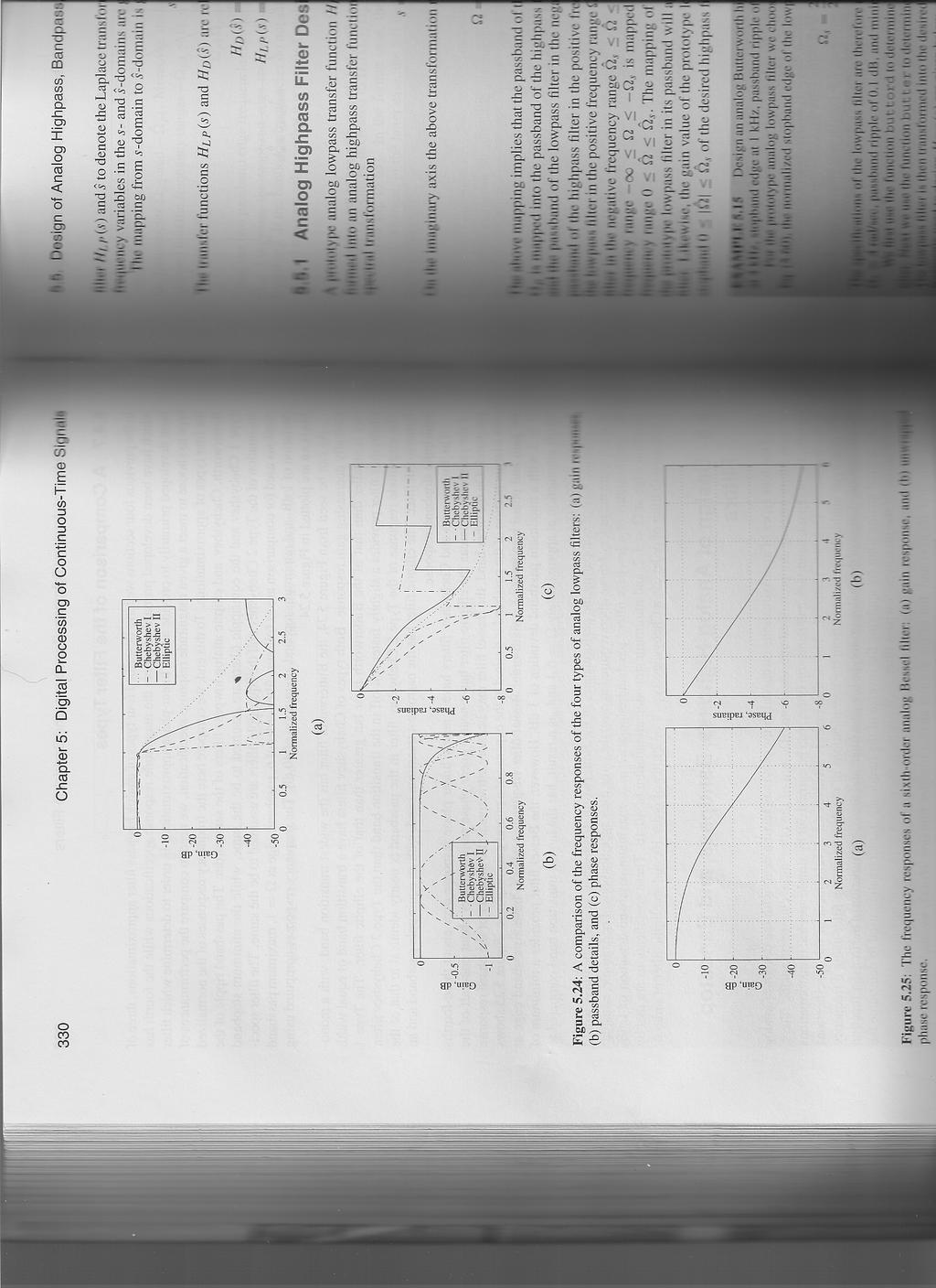
Digital Processing of Continuous-Time Signals
 Chapter 4 Digital Processing of Continuous-Time Signals 清大電機系林嘉文 cwlin@ee.nthu.edu.tw 03-5731152 Original PowerPoint slides prepared by S. K. Mitra 4-1-1 Digital Processing of Continuous-Time Signals Digital
Digital Processing of
 Chapter 4 Digital Processing of Continuous-Time Signals 清大電機系林嘉文 cwlin@ee.nthu.edu.tw 03-5731152 Original PowerPoint slides prepared by S. K. Mitra 4-1-1 Digital Processing of Continuous-Time Signals Digital
NOVEMBER 13, 1996 EE 4773/6773: LECTURE NO. 37 PAGE 1 of 5
 NOVEMBER 3, 996 EE 4773/6773: LECTURE NO. 37 PAGE of 5 Characteristics of Commonly Used Analog Filters - Butterworth Butterworth filters are maimally flat in the passband and stopband, giving monotonicity
UNIT-II MYcsvtu Notes agk
 UNIT-II agk UNIT II Infinite Impulse Response Filter design (IIR): Analog & Digital Frequency transformation. Designing by impulse invariance & Bilinear method. Butterworth and Chebyshev Design Method.
APPENDIX A to VOLUME A1 TIMS FILTER RESPONSES
 APPENDIX A to VOLUME A1 TIMS FILTER RESPONSES A2 TABLE OF CONTENTS... 5 Filter Specifications... 7 3 khz LPF (within the HEADPHONE AMPLIFIER)... 8 TUNEABLE LPF... 9 BASEBAND CHANNEL FILTERS - #2 Butterworth
IIR Filter Design Chapter Intended Learning Outcomes: (i) Ability to design analog Butterworth filters
 Ability to design analog Butterworth filters") IIR Filter Design Chapter Intended Learning Outcomes: (i) Ability to design analog Butterworth filters (ii) Ability to design lowpass IIR filters according to predefined specifications based on analog
IIR Filter Design Chapter Intended Learning Outcomes: (i) Ability to design analog Butterworth filters (ii) Ability to design lowpass IIR filters according to predefined specifications based on analog
LECTURER NOTE SMJE3163 DSP
 LECTURER NOTE SMJE363 DSP (04/05-) ------------------------------------------------------------------------- Week3 IIR Filter Design -------------------------------------------------------------------------
EEO 401 Digital Signal Processing Prof. Mark Fowler
 EEO 4 Digital Signal Processing Prof. Mark Fowler Note Set #34 IIR Design Characteristics of Common Analog Filters Reading: Sect..3.4 &.3.5 of Proakis & Manolakis /6 Motivation We ve seenthat the Bilinear
3 Analog filters. 3.1 Analog filter characteristics
 Chapter 3, page 1 of 11 3 Analog filters This chapter deals with analog filters and the filter approximations of an ideal filter. The filter approximations that are considered are the classical analog
Infinite Impulse Response (IIR) Filter. Ikhwannul Kholis, ST., MT. Universitas 17 Agustus 1945 Jakarta
 Filter. Ikhwannul Kholis, ST., MT. Universitas 17 Agustus 1945 Jakarta") Infinite Impulse Response (IIR) Filter Ihwannul Kholis, ST., MT. Universitas 17 Agustus 1945 Jaarta The Outline 8.1 State-of-the-art 8.2 Coefficient Calculation Method for IIR Filter 8.2.1 Pole-Zero Placement
Infinite Impulse Response (IIR) Filter Ihwannul Kholis, ST., MT. Universitas 17 Agustus 1945 Jaarta The Outline 8.1 State-of-the-art 8.2 Coefficient Calculation Method for IIR Filter 8.2.1 Pole-Zero Placement
Kerwin, W.J. Passive Signal Processing The Electrical Engineering Handbook Ed. Richard C. Dorf Boca Raton: CRC Press LLC, 2000
 Kerwin, W.J. Passive Signal Processing The Electrical Engineering Handbook Ed. Richard C. Dorf Boca Raton: CRC Press LLC, 000 4 Passive Signal Processing William J. Kerwin University of Arizona 4. Introduction
Continuous-Time Analog Filters
 ENGR 4333/5333: Digital Signal Processing Continuous-Time Analog Filters Chapter 2 Dr. Mohamed Bingabr University of Central Oklahoma Outline Frequency Response of an LTIC System Signal Transmission through
Filters. Phani Chavali
 Filters Phani Chavali Filters Filtering is the most common signal processing procedure. Used as echo cancellers, equalizers, front end processing in RF receivers Used for modifying input signals by passing
ECE 203 LAB 2 PRACTICAL FILTER DESIGN & IMPLEMENTATION
 Version 1. 1 of 7 ECE 03 LAB PRACTICAL FILTER DESIGN & IMPLEMENTATION BEFORE YOU BEGIN PREREQUISITE LABS ECE 01 Labs ECE 0 Advanced MATLAB ECE 03 MATLAB Signals & Systems EXPECTED KNOWLEDGE Understanding
PHYS225 Lecture 15. Electronic Circuits
 PHYS225 Lecture 15 Electronic Circuits Last lecture Difference amplifier Differential input; single output Good CMRR, accurate gain, moderate input impedance Instrumentation amplifier Differential input;
NH 67, Karur Trichy Highways, Puliyur C.F, Karur District DEPARTMENT OF INFORMATION TECHNOLOGY DIGITAL SIGNAL PROCESSING UNIT 3
 NH 67, Karur Trichy Highways, Puliyur C.F, 639 114 Karur District DEPARTMENT OF INFORMATION TECHNOLOGY DIGITAL SIGNAL PROCESSING UNIT 3 IIR FILTER DESIGN Structure of IIR System design of Discrete time
Lowpass Filters. Microwave Filter Design. Chp5. Lowpass Filters. Prof. Tzong-Lin Wu. Department of Electrical Engineering National Taiwan University
 Microwave Filter Design Chp5. Lowpass Filters Prof. Tzong-Lin Wu Department of Electrical Engineering National Taiwan University Lowpass Filters Design steps Select an appropriate lowpass filter prototype
4/14/15 8:58 PM C:\Users\Harrn...\tlh2polebutter10rad see.rn 1 of 1
 4/14/15 8:58 PM C:\Users\Harrn...\tlh2polebutter10rad see.rn 1 of 1 % Example 2pole butter tlh % Analog Butterworth filter design % design an 2-pole filter with a bandwidth of 10 rad/sec % Prototype H(s)
Brief Introduction to Signals & Systems. Phani Chavali
 Brief Introduction to Signals & Systems Phani Chavali Outline Signals & Systems Continuous and discrete time signals Properties of Systems Input- Output relation : Convolution Frequency domain representation
Filters and Tuned Amplifiers
 CHAPTER 6 Filters and Tuned Amplifiers Introduction 55 6. Filter Transmission, Types, and Specification 56 6. The Filter Transfer Function 60 6.7 Second-Order Active Filters Based on the Two-Integrator-Loop
EEL 3923C. JD/ Module 3 Elementary Analog Filter Design. Prof. T. Nishida Fall 2010
 EEL 3923C JD/ Module 3 Elementary Analog Filter Design Prof. T. Nishida Fall 2010 Purpose Frequency selection Low pass, high pass, band pass, band stop, notch, etc. Applications II. Filter Fundamentals
8: IIR Filter Transformations
 DSP and Digital (5-677) IIR : 8 / Classical continuous-time filters optimize tradeoff: passband ripple v stopband ripple v transition width There are explicit formulae for pole/zero positions. Butterworth:
(i) Understanding of the characteristics of linear-phase finite impulse response (FIR) filters
 Understanding of the characteristics of linear-phase finite impulse response (FIR) filters") FIR Filter Design Chapter Intended Learning Outcomes: (i) Understanding of the characteristics of linear-phase finite impulse response (FIR) filters (ii) Ability to design linear-phase FIR filters according
FIR Filter Design Chapter Intended Learning Outcomes: (i) Understanding of the characteristics of linear-phase finite impulse response (FIR) filters (ii) Ability to design linear-phase FIR filters according
Octave Functions for Filters. Young Won Lim 2/19/18
 Copyright (c) 2016 2018 Young W. Lim. Permission is granted to copy, distribute and/or modify this document under the terms of the GNU Free Documentation License, Version 1.2 or any later version published
(Refer Slide Time: 02:00-04:20) (Refer Slide Time: 04:27 09:06)
 (Refer Slide Time: 04:27 09:06)") Digital Signal Processing Prof. S. C. Dutta Roy Department of Electrical Engineering Indian Institute of Technology, Delhi Lecture - 25 Analog Filter Design (Contd.); Transformations This is the 25 th
Digital Signal Processing Prof. S. C. Dutta Roy Department of Electrical Engineering Indian Institute of Technology, Delhi Lecture - 25 Analog Filter Design (Contd.); Transformations This is the 25 th
ELEC-C5230 Digitaalisen signaalinkäsittelyn perusteet
 ELEC-C5230 Digitaalisen signaalinkäsittelyn perusteet Lecture 10: Summary Taneli Riihonen 16.05.2016 Lecture 10 in Course Book Sanjit K. Mitra, Digital Signal Processing: A Computer-Based Approach, 4th
Electric Circuit Theory
 Electric Circuit Theory Nam Ki Min nkmin@korea.ac.kr 010-9419-2320 Chapter 15 Active Filter Circuits Nam Ki Min nkmin@korea.ac.kr 010-9419-2320 Contents and Objectives 3 Chapter Contents 15.1 First-Order
Discretization of Continuous Controllers
 Discretization of Continuous Controllers Thao Dang VERIMAG, CNRS (France) Discretization of Continuous Controllers One way to design a computer-controlled control system is to make a continuous-time design
Filter Approximation Concepts
 6 (ESS) Filter Approximation Concepts How do you translate filter specifications into a mathematical expression which can be synthesized? Approximation Techniques Why an ideal Brick Wall Filter can not
4. K. W. Henderson, "Nomograph for Designing Elliptic-Function Filters," Proc. IRE, vol. 46, pp , 1958.
 BIBLIOGRAPHY Books. W. Cauer, Synthesis of Linear Communication Networks (English translation from German edition), McGraw-Hill Book Co., New York, 958. 2. W. K. Chen, Theory and Design of Broadband Matching
Review of Filter Types
 ECE 440 FILTERS Review of Filters Filters are systems with amplitude and phase response that depends on frequency. Filters named by amplitude attenuation with relation to a transition or cutoff frequency.
Design of IIR Digital Filters with Flat Passband and Equiripple Stopband Responses
 Electronics and Communications in Japan, Part 3, Vol. 84, No. 11, 2001 Translated from Denshi Joho Tsushin Gakkai Ronbunshi, Vol. J82-A, No. 3, March 1999, pp. 317 324 Design of IIR Digital Filters with
Filters occur so frequently in the instrumentation and
 FILTER Design CHAPTER 3 Filters occur so frequently in the instrumentation and communications industries that no book covering the field of RF circuit design could be complete without at least one chapter
Chapter 7 Filter Design Techniques. Filter Design Techniques
 Chapter 7 Filter Design Techniques Page 1 Outline 7.0 Introduction 7.1 Design of Discrete Time IIR Filters 7.2 Design of FIR Filters Page 2 7.0 Introduction Definition of Filter Filter is a system that
Chapter 15: Active Filters
 Chapter 15: Active Filters 15.1: Basic filter Responses A filter is a circuit that passes certain frequencies and rejects or attenuates all others. The passband is the range of frequencies allowed to pass
DIGITAL FILTERS. !! Finite Impulse Response (FIR) !! Infinite Impulse Response (IIR) !! Background. !! Matlab functions AGC DSP AGC DSP
 !! Infinite Impulse Response (IIR) !! Background. !! Matlab functions AGC DSP AGC DSP") DIGITAL FILTERS!! Finite Impulse Response (FIR)!! Infinite Impulse Response (IIR)!! Background!! Matlab functions 1!! Only the magnitude approximation problem!! Four basic types of ideal filters with magnitude
DIGITAL FILTERS!! Finite Impulse Response (FIR)!! Infinite Impulse Response (IIR)!! Background!! Matlab functions 1!! Only the magnitude approximation problem!! Four basic types of ideal filters with magnitude
Butterworth, Elliptic, Chebychev Filters
 Objective: Butterworth, Elliptic, Chebychev Filters Know what each filter tries to optimize Know how these filters compare An ideal low pass filter has a gain of one in the passband, zero outside that
Using the isppac 80 Programmable Lowpass Filter IC
 Using the isppac Programmable Lowpass Filter IC Introduction This application note describes the isppac, an In- System Programmable (ISP ) Analog Circuit from Lattice Semiconductor, and the filters that
DESIGN OF FIR AND IIR FILTERS
 DESIGN OF FIR AND IIR FILTERS Ankit Saxena 1, Nidhi Sharma 2 1 Department of ECE, MPCT College, Gwalior, India 2 Professor, Dept of Electronics & Communication, MPCT College, Gwalior, India Abstract This
Microwave Circuits Design. Microwave Filters. high pass
 Used to control the frequency response at a certain point in a microwave system by providing transmission at frequencies within the passband of the filter and attenuation in the stopband of the filter.
Rahman Jamal, et. al.. "Filters." Copyright 2000 CRC Press LLC. <
 Rahman Jamal, et. al.. "Filters." Copyright 000 CRC Press LLC. . Filters Rahman Jamal National Instruments Germany Robert Steer Frequency Devices 8. Introduction 8. Filter Classification
DAPL IIR Filter Module Manual
 DAPL IIR Filter Module Manual DAPL IIR Filter Module applications and command reference Version 1.00 Microstar Laboratories, Inc. This manual contains proprietary information which is protected by copyright.
VCC. Digital 16 Frequency Divider Digital-to-Analog Converter Butterworth Active Filter Sample-and-Hold Amplifier (part 2) Last Update: 03/19/14
 Last Update: 03/19/14") Digital 16 Frequency Divider Digital-to-Analog Converter Butterworth Active Filter Sample-and-Hold Amplifier (part 2) ECE3204 Lab 5 Objective The purpose of this lab is to design and test an active Butterworth
Digital 16 Frequency Divider Digital-to-Analog Converter Butterworth Active Filter Sample-and-Hold Amplifier (part 2) ECE3204 Lab 5 Objective The purpose of this lab is to design and test an active Butterworth
ECE 4213/5213 Homework 10
 Fall 2017 ECE 4213/5213 Homework 10 Dr. Havlicek Work the Projects and Questions in Chapter 7 of the course laboratory manual. For your report, use the file LABEX7.doc from the course web site. Work these
Signal processing preliminaries
 Signal processing preliminaries ISMIR Graduate School, October 4th-9th, 2004 Contents: Digital audio signals Fourier transform Spectrum estimation Filters Signal Proc. 2 1 Digital signals Advantages of
F I R Filter (Finite Impulse Response)
") F I R Filter (Finite Impulse Response) Ir. Dadang Gunawan, Ph.D Electrical Engineering University of Indonesia The Outline 7.1 State-of-the-art 7.2 Type of Linear Phase Filter 7.3 Summary of 4 Types FIR
F I R Filter (Finite Impulse Response) Ir. Dadang Gunawan, Ph.D Electrical Engineering University of Indonesia The Outline 7.1 State-of-the-art 7.2 Type of Linear Phase Filter 7.3 Summary of 4 Types FIR
Design of infinite impulse response (IIR) bandpass filter structure using particle swarm optimization
 bandpass filter structure using particle swarm optimization") Standard Scientific Research and Essays Vol1 (1): 1-8, February 13 http://www.standresjournals.org/journals/ssre Research Article Design of infinite impulse response (IIR) bandpass filter structure using
Standard Scientific Research and Essays Vol1 (1): 1-8, February 13 http://www.standresjournals.org/journals/ssre Research Article Design of infinite impulse response (IIR) bandpass filter structure using
RMS. CATV Broadband Products FILTERS. Connectors Trunk series Drop series Adapters
 RMS FILTERS CATV Broadband Products Connectors Trunk series Drop series Adapters Filters High-pass Low-pass Band-rejection Band-pass RSA attenuator Windows CERTIFICATE NO.4991 Highpass Filter Return Path
Comparative Study of RF/microwave IIR Filters by using the MATLAB
 Comparative Study of RF/microwave IIR Filters by using the MATLAB Ravi kant doneriya,prof. Laxmi shrivastava Abstract In recent years, due to the magnificent development of Filter designs take attention
CHAPTER 8 ANALOG FILTERS
 ANALOG FILTERS CHAPTER 8 ANALOG FILTERS SECTION 8.: INTRODUCTION 8. SECTION 8.2: THE TRANSFER FUNCTION 8.5 THE SPLANE 8.5 F O and Q 8.7 HIGHPASS FILTER 8.8 BANDPASS FILTER 8.9 BANDREJECT (NOTCH) FILTER
Narrow-Band and Wide-Band Frequency Masking FIR Filters with Short Delay
 Narrow-Band and Wide-Band Frequency Masking FIR Filters with Short Delay Linnéa Svensson and Håkan Johansson Department of Electrical Engineering, Linköping University SE8 83 Linköping, Sweden linneas@isy.liu.se
Fig 1 describes the proposed system. Keywords IIR, FIR, inverse Chebyshev, Elliptic, LMS, RLS.
 Design of approximately linear phase sharp cut-off discrete-time IIR filters using adaptive linear techniques of channel equalization. IIT-Madras R.Sharadh, Dual Degree--Communication Systems rsharadh@yahoo.co.in
o algorithmic method (where the processor calculates new circuit programming data) or
 or") Rev:.0.0 Date: th March 004 Purpose This document describes how to dynamically program high-order filters using AnadigmDesigner using algorithmic dynamic reconfiguration. AnadigmDesigner supports two powerful
Rev:.0.0 Date: th March 004 Purpose This document describes how to dynamically program high-order filters using AnadigmDesigner using algorithmic dynamic reconfiguration. AnadigmDesigner supports two powerful
ECE580 Make-up Project 2: Filter Design. November, 30 th 2012
 General Stopband Filter Design Report ECE580 Make-up Project 2: Filter Design by Arne Bostrom, Rick Crispo and Erin Sullivan November, 30 th 2012 Problem Statement The purpose of this project is to find
Window Method. designates the window function. Commonly used window functions in FIR filters. are: 1. Rectangular Window:
 Window Method We have seen that in the design of FIR filters, Gibbs oscillations are produced in the passband and stopband, which are not desirable features of the FIR filter. To solve this problem, window
EKT 356 MICROWAVE COMMUNICATIONS CHAPTER 4: MICROWAVE FILTERS
 EKT 356 MICROWAVE COMMUNICATIONS CHAPTER 4: MICROWAVE FILTERS 1 INTRODUCTION What is a Microwave filter? linear 2-port network controls the frequency response at a certain point in a microwave system provides
Designing Filters Using the NI LabVIEW Digital Filter Design Toolkit
 Application Note 097 Designing Filters Using the NI LabVIEW Digital Filter Design Toolkit Introduction The importance of digital filters is well established. Digital filters, and more generally digital
Live Health Short-term Baseline Preliminary User Guide
 Live Health Short-term Baseline Preliminary User Guide Create Date: February 28, 27 Last Modified Date: April 4, 27 Version. Copyright 27 Computer Associates International, Inc. Staples Drive Framingham,
ELEC3104: Digital Signal Processing Session 1, 2013
 ELEC3104: Digital Signal Processing Session 1, 2013 The University of New South Wales School of Electrical Engineering and Telecommunications LABORATORY 4: DIGITAL FILTERS INTRODUCTION In this laboratory,
Introduction (cont )
") Active Filter 1 Introduction Filters are circuits that are capable of passing signals within a band of frequencies while rejecting or blocking signals of frequencies outside this band. This property of
Active Filter 1 Introduction Filters are circuits that are capable of passing signals within a band of frequencies while rejecting or blocking signals of frequencies outside this band. This property of
NAPIER. University School of Engineering. Engineering Applications Module : SE32101 Active Filter Design 2 nd order Butterworth response
 NAPIER. University School of Engineering Engineering Applications Module : SE3101 nd order Butterworth response C1 4.7n 15V + R1 7.04k R 14.09k In C 4.7n OP1 ua741 + + - R3 10k -15V Out Sallen and key.
AUDIO SIEVING USING SIGNAL FILTERS
 AUDIO SIEVING USING SIGNAL FILTERS A project under V.6.2 Signals and System Engineering Yatharth Aggarwal Sagar Mayank Chauhan Rajan Table of Contents Introduction... 2 Filters... 4 Butterworth Filter...
Part B. Simple Digital Filters. 1. Simple FIR Digital Filters
 Simple Digital Filters Chapter 7B Part B Simple FIR Digital Filters LTI Discrete-Time Systems in the Transform-Domain Simple Digital Filters Simple IIR Digital Filters Comb Filters 3. Simple FIR Digital
Dorf, R.C., Wan, Z. Transfer Functions of Filters The Electrical Engineering Handbook Ed. Richard C. Dorf Boca Raton: CRC Press LLC, 2000
 Dorf, R.C., Wan, Z. Transfer Functions of Filters The Electrical Engineering Handbook Ed. Richard C. Dorf oca Raton: CRC Press LLC, Transfer Functions of Filters Richard C. Dorf University of California,
HIGH FREQUENCY FILTERING OF 24-HOUR HEART RATE DATA
 HIGH FREQUENCY FILTERING OF 24-HOUR HEART RATE DATA Albinas Stankus, Assistant Prof. Mechatronics Science Institute, Klaipeda University, Klaipeda, Lithuania Institute of Behavioral Medicine, Lithuanian
Electronic PRINCIPLES
 MALVINO & BATES Electronic PRINCIPLES SEVENTH EDITION Chapter 21 Active Filters Topics Covered in Chapter 21 Ideal responses Approximate responses Passive ilters First-order stages VCVS unity-gain second-order
Part Numbering System
 Reactel Filters can satisfy a variety of filter requirements. These versatile units cover the broad frequency range of 2 khz to 5 GHz, and are available in either tubular or rectangular packages, connectorized
Lecture 17 z-transforms 2
 Lecture 17 z-transforms 2 Fundamentals of Digital Signal Processing Spring, 2012 Wei-Ta Chu 2012/5/3 1 Factoring z-polynomials We can also factor z-transform polynomials to break down a large system into
Multirate DSP, part 1: Upsampling and downsampling
 Multirate DSP, part 1: Upsampling and downsampling Li Tan - April 21, 2008 Order this book today at www.elsevierdirect.com or by calling 1-800-545-2522 and receive an additional 20% discount. Use promotion
Design Digital Non-Recursive FIR Filter by Using Exponential Window
 International Journal of Emerging Engineering Research and Technology Volume 3, Issue 3, March 2015, PP 51-61 ISSN 2349-4395 (Print) & ISSN 2349-4409 (Online) Design Digital Non-Recursive FIR Filter by
System on a Chip. Prof. Dr. Michael Kraft
 System on a Chip Prof. Dr. Michael Kraft Lecture 4: Filters Filters General Theory Continuous Time Filters Background Filters are used to separate signals in the frequency domain, e.g. remove noise, tune
Figure z1, Direct Programming Method ... Numerator Denominator... Vo/Vi = N(1+D1) Vo(1+D ) = ViN Vo = ViN-VoD
 Vo(1+D ) = ViN Vo = ViN-VoD") Z Transform Basics Design and analysis of control systems are usually performed in the frequency domain; where the time domain process of convolution is replaced by a simple process of multiplication of
Z Transform Basics Design and analysis of control systems are usually performed in the frequency domain; where the time domain process of convolution is replaced by a simple process of multiplication of
Final Exam Solutions June 14, 2006
 Name or 6-Digit Code: PSU Student ID Number: Final Exam Solutions June 14, 2006 ECE 223: Signals & Systems II Dr. McNames Keep your exam flat during the entire exam. If you have to leave the exam temporarily,
Keywords FIR lowpass filter, transition bandwidth, sampling frequency, window length, filter order, and stopband attenuation.
 Volume 7, Issue, February 7 ISSN: 77 8X International Journal of Advanced Research in Computer Science and Software Engineering Research Paper Available online at: www.ijarcsse.com Estimation and Tuning
A PACKAGE FOR FILTER DESIGN BASED ON MATLAB
 A PACKAGE FOR FILTER DESIGN BASED ON MATLAB David Báez-López 1, David Báez-Villegas 2, René Alcántara 3, Juan José Romero 1, and Tomás Escalante 1 Session F4D Abstract Electric filters have a relevant
Massachusetts Institute of Technology Department of Electrical Engineering & Computer Science 6.341: Discrete-Time Signal Processing Fall 2005
 Massachusetts Institute of Technology Department of Electrical Engineering & Computer Science 6.341: Discrete-Time Signal Processing Fall 2005 Project Assignment Issued: Sept. 27, 2005 Project I due: Nov.
Transfer function: a mathematical description of network response characteristics.
 Microwave Filter Design Chp3. Basic Concept and Theories of Filters Prof. Tzong-Lin Wu Department of Electrical Engineering National Taiwan University Transfer Functions General Definitions Transfer function:
The above figure represents a two stage circuit. Recall, the transfer function relates. Vout
 LABORATORY 12: Bode plots/second Order Filters Material covered: Multistage circuits Bode plots Design problem Overview Notes: Two stage circuits: Vin1 H1(s) Vout1 Vin2 H2(s) Vout2 The above figure represents
Decoding a Signal in Noise
 Department of Electrical & Computer Engineering McGill University ECSE-490 DSP Laboratory Experiment 2 Decoding a Signal in Noise 2.1 Purpose Imagine that you have obtained through some, possibly suspect,
Instruction Manual DFP2 Digital Filter Package
 Instruction Manual DFP2 Digital Filter Package Digital Filter Package 2 Software Instructions 2017 Teledyne LeCroy, Inc. All rights reserved. Unauthorized duplication of Teledyne LeCroy, Inc. documentation
ISOlinear Architecture. Silicon Labs CMOS Isolator. Figure 1. ISOlinear Design Architecture. Table 1. Circuit Performance mv 0.
 ISOLATING ANALOG SIGNALS USING THE Si86XX CMOS ISOLATOR FAMILY. Introduction AN559 The ISOlinear reference design (Si86ISOLIN-KIT) provides galvanic isolation for analog signals over a frequency range
Frequency-Response Masking FIR Filters
 Frequency-Response Masking FIR Filters Georg Holzmann June 14, 2007 With the frequency-response masking technique it is possible to design sharp and linear phase FIR filters. Therefore a model filter and
Copyright S. K. Mitra
 1 In many applications, a discrete-time signal x[n] is split into a number of subband signals by means of an analysis filter bank The subband signals are then processed Finally, the processed subband signals
EE247 Lecture 2. Butterworth Chebyshev I Chebyshev II Elliptic Bessel Group delay comparison example. EECS 247 Lecture 2: Filters
 EE247 Lecture 2 Material covered today: Nomenclature Filter specifications Quality factor Frequency characteristics Group delay Filter types Butterworth Chebyshev I Chebyshev II Elliptic Bessel Group delay
Design IIR Filter using MATLAB
 International Journal of Science, Engineering and Technology Research (IJSETR), Volume 4, Issue 2, December 25 Design IIR Filter using MATLAB RainuArya Abstract in Digital Signal Processing (DSP), most
ijdsp Workshop: Exercise 2012 DSP Exercise Objectives
 Objectives DSP Exercise The objective of this exercise is to provide hands-on experiences on ijdsp. It consists of three parts covering frequency response of LTI systems, pole/zero locations with the frequency
Digital Filter Design
 Chapter9 Digital Filter Design Contents 9.1 Overview of Approximation Techniques........ 9-3 9.1.1 Approximation Approaches........... 9-3 9.1.2 FIR Approximation Approaches......... 9-3 9.2 Continuous-Time
Active Filter Design Techniques
 Active Filter Design Techniques 16.1 Introduction What is a filter? A filter is a device that passes electric signals at certain frequencies or frequency ranges while preventing the passage of others.
EE247 - Lecture 2 Filters. EECS 247 Lecture 2: Filters 2005 H.K. Page 1. Administrative. Office hours for H.K. changed to:
 EE247 - Lecture 2 Filters Material covered today: Nomenclature Filter specifications Quality factor Frequency characteristics Group delay Filter types Butterworth Chebyshev I Chebyshev II Elliptic Bessel
Narrow-Band Low-Pass Digital Differentiator Design. Ivan Selesnick Polytechnic University Brooklyn, New York
 Narrow-Band Low-Pass Digital Differentiator Design Ivan Selesnick Polytechnic University Brooklyn, New York selesi@poly.edu http://taco.poly.edu/selesi 1 Ideal Lowpass Digital Differentiator The frequency
Application Note 7. Digital Audio FIR Crossover. Highlights Importing Transducer Response Data FIR Window Functions FIR Approximation Methods
 Application Note 7 App Note Application Note 7 Highlights Importing Transducer Response Data FIR Window Functions FIR Approximation Methods n Design Objective 3-Way Active Crossover 200Hz/2kHz Crossover
Bode plot, named after Hendrik Wade Bode, is usually a combination of a Bode magnitude plot and Bode phase plot:
 Bode plot From Wikipedia, the free encyclopedia A The Bode plot for a first-order (one-pole) lowpass filter Bode plot, named after Hendrik Wade Bode, is usually a combination of a Bode magnitude plot and
ME411 Engineering Measurement & Instrumentation. Winter 2017 Lecture 3
 ME411 Engineering Measurement & Instrumentation Winter 2017 Lecture 3 1 Current Measurement DC or AC current Use of a D Arsonval Meter - electric current carrying conductor passing through a magnetic field
Signals and Systems Lecture 6: Fourier Applications
 Signals and Systems Lecture 6: Fourier Applications Farzaneh Abdollahi Department of Electrical Engineering Amirkabir University of Technology Winter 2012 arzaneh Abdollahi Signal and Systems Lecture 6
Florida International University
 Florida International University College of Electrical Engineering Digital Filters A Practical Method to Design Equiripple FIR Filters Author: Pablo Gomez, Ph.D. Candidate Miami, November, 2001 Abstract
EE 230 Lecture 39. Data Converters. Time and Amplitude Quantization
 EE 230 Lecture 39 Data Converters Time and Amplitude Quantization Review from Last Time: Time Quantization How often must a signal be sampled so that enough information about the original signal is available
A filter is appropriately described by the transfer function. It is a ratio between two polynomials
 Imaginary Part Matlab examples Filter description A filter is appropriately described by the transfer function. It is a ratio between two polynomials H(s) = N(s) D(s) = b ns n + b n s n + + b s a m s m
ALMA Memo 452: Passband Shape Deviation Limits Larry R. D Addario 2003 April 09
 ALMA Memo 452: Passband Shape Deviation Limits Larry R. D Addario 23 April 9 Abstract. Beginning with the ideal passband, which is constant from Nf s /2 to (N + 1)f s /2 and zero elsewhere, where N =,
Number of Sections. Contact factory for specific requirements not listed above.
 Tubular Filters MHz to 20 GHz Chebyshev Response Standard 4 Convenient Sizes Reliable Sturdy Construction Lorch Microwave tubular filters are available in bandpass and lowpass configurations. A low ripple