Chapter 19. Basic Filters
|
|
|
- Gertrude Malone
- 5 years ago
- Views:
Transcription
1 Chapter 19 Basic Filters
2 Objectives Analyze the operation of RC and RL lowpass filters Analyze the operation of RC and RL highpass filters Analyze the operation of band-pass filters Analyze the operation of band-stop filters Investigate a real-world application of filters
3 Low-Pass Filters The range of low frequencies passed by a low-pass filter within a specified limit is called the passband (or bandpass) of the filter. The point considered to be the upper end of the passband is at the critical frequency (f c ). Lowpass filters have an upper critical frequency usually denoted as f CH. Critical frequency is the frequency at which the filter s output voltage is 70.7% of the maximum. Critical frequency is also called the cutoff frequency, break frequency, or -3dB frequency.

4 Figure Low-pass filter block diagram and response curve. Non-ideal: Frequencies from 0 Hz to -3dB are said to be in the passband. Frequencies greater than -3dB but less than or equal to -6dB are said to be in the transition band. Frequencies greater than -6dB are said to be in the stopband.
5 Low-Pass Filters For an RC low-pass filter, the output voltage is taken across the capacitor. For an RL low-pass filter, the output voltage is taken across the resistor.
6 RC Low-Pass Filter When the input is dc, the output voltage equals the input voltage because X C is infinitely large. As the input frequency is increased, X C decreases. As X C decreases, V out also decreases. The critical frequency (f c ) of the filter is reached when X C = R: f c = 1/(2 RC)
7 RC Low-Pass Filter At any frequency, the output voltage magnitude is: V out = (X C / R 2 + X 2 C)V in The ratio of output voltage to input voltage at the critical frequency can be expressed in decibels as: 20 log(v out /V in ) = -3 db
8 RC Low-Pass Filters (Inverted-L) IT = ES/ZT VR = IT x R VC = IT x XC This is a LAG network: VC (Vout) lags ES by (-90 + θ = φ) By Convention, φ is used to denote phase for filter circuits. The distinction between θ and φ is removed when dealing with filter circuits. We use only one symbol φ (phi) to denote phase on filter phasor diagrams.
9 The RC Circuit as a Low Pass Filter The RC Low Pass Filter is also an AC voltage divider, with R the output taken across the Capacitor. Es Vout V OUT = (X C / R 2 +X C2 ) x E S C Xc At low f, X C increases, so R is negligible and V OUT E S, so little attenuation; this is the pass band. At f c, V C = V R because R = X C ; V OUT = E S / 2 or (0.707)E S or 3dB. At f > f c, V OUT decreases, and becomes the stop band. Insertion loss or db ATTEN = 20 log V OUT /V IN = 20 log (X C / R 2 +X C2 )
10 RL Low-Pass Filter The output voltage is taken across the resistor. When the input is dc, the output voltage equals the input voltage because X L is a short. As the input frequency is increased, X L increases. As X L increases, V out decreases. The critical frequency (f c ) of the filter is reached when X L = R: f c = 1/(2 (L/R))
11 RL Low-Pass Filters (Inverted-L) ES = VR + jvl ZT = R + jxl This is a LAG network: VR lags ES by θ By Convention, φ is used to denote phase for filter circuits. The distinction between θ and φ is removed when dealing with filter circuits. We use only one symbol φ (phi) to denote phase on filter phasor diagrams.
12 The RL Circuit as a Low Pass Filter The RL Low Pass Filter is also an AC voltage divider, with the output taken across the Resistor. L V OUT = (R/ R 2 +X L2 ) x E S Es R At low f, X L decreases, so X L is negligible and V OUT E S, so little attenuation; this is the pass band. At f c, V L = V R because R = X L ; V OUT = E S / 2 or (0.707)E S or 3dB. At f > f c, V OUT decreases, and becomes the stop band. Insertion loss or db ATTEN = 20 log V OUT /V IN = 20 log (R/ R 2 +X L2 )
13 Response Curve Roll-Off The maximum output is defined to be 0 db as a reference (V out = V in ). The output drops from 0 db to -3 db at cutoff. Output drops at a fixed roll-off rate above cutoff.
14 Attenuation for a Basic RC or RL Low-Pass Circuit The roll-off rate, or attenuation, as the frequency continues to increase above f C is at -20 db for each tenfold increase in frequency (or -6dB/octave). A tenfold change in frequency is called a decade. The roll-off is a constant -20 db/decade for a basic RC or RL filter (or -6dB/octave). Frequencies from 0Hz to f c are said to be in the passband of the filter. Frequencies above f c are said to be in the stopband of the filter. The frequency response is plotted on a semilog scale. The response curve is called a Bode plot.
15 RC or RL Low-Pass Filter Response Bode Plot
16 Phase Shift in a Low-Pass Filter The RC low-pass filter acts as a lag network. The phase shift between output and input is: = tan -1 (X C /R) The RL low-pass filter also acts as a lag network. The phase shift between output and input is: θ = -tan -1 (X L /R) (which is denoted as on phase-shift diagrams) At the critical frequency, in both cases, phase-shift = -45. As f approaches 0 Hz, decreases and approaches 0.
17 Low-Pass Filters Example 1 Determine the output voltage of each filter below at the specified frequency when Vin = 10V. Determine f c for each filter.

")
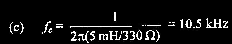
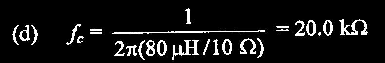
18 Low-Pass Filters Example 1 (cont.)
19 Low-Pass Filters Example 2 For the filter below, calculate the value of C required for each of the following critical frequencies: (a) 60 Hz (b) 500 Hz (c) 1kHz (d) 5kHz Draw the idealized Bode plot for each critical frequency above.
20 Low-Pass Filters Example 2 (cont.)

21 Low-Pass Filters Example 2 (cont.)
22 The Order Of A Filter Filters are often expressed with respect to the rolloff rate designated as the number of poles or the filter order. Poles are defined as the number of capacitors or inductors used in a filter. There are some exceptions to this rule. More on this later!!! Each pole introduces a -20dB/decade roll-off rate. For example, a two-pole filter or second order filter will have a -40dB/decade roll-off rate.
23 Increasing Low-Pass RC Filter Roll-off Rates The number of poles or the order of RC low pass filters is defined as the number of capacitors used. The T and Inverted-L configurations are first-order filters (per section) while the PI configuration is a second-order filter.
24 Increasing Low-Pass RL Filter Roll-off Rates The number of poles or the order of RL low pass filters is defined as the number of inductors used. The PI and Inverted-L configurations are first-order filters (per section) while the T configuration is a second-order filter.
25 High-Pass Filters A high-pass filter allows signals with higher frequencies to pass from input to output while rejecting lower frequencies. The range of high frequencies passed by a highpass filter within a specified limit is called the passband (or bandpass) of the filter. The frequency considered to be the lower end of the passband is called the critical frequency f c or f CH. The critical frequency has an output which is 70.7% of the maximum.

26 Figure High-pass filter block diagram and response curve. Non-ideal: Frequencies from 0 Hz to less than -6dB are said to be in the stopband. Frequencies greater than or equal to -6dB but less than -3dB are said to be in the transition band. Frequencies greater than or equal to -3dB are said to be in the passband.
27 High-Pass Filters For an RC high-pass filter, the output voltage is taken across the resistor. For an RL high-pass filter, the output voltage is taken across the inductor.
28 RC High-Pass Filter When the input frequency is at its critical value, X C =R, the output voltage is 0.707V (-3dB). As the input frequency increases above f C, X C decreases. As X C decreases, the output voltage increases, approaching the value of V in. The critical frequency is: f c = 1/2 RC
29 RC High-Pass Filters (Inverted-L) ES = VR jvc ZT = R jxc This is a LEAD network: VR leads ES by θ By Convention, φ is used to denote phase for filter circuits. The distinction between θ and φ is removed when dealing with filter circuits. We use only one symbol φ (phi) to denote phase on filter phasor diagrams.
30 The RC Circuit as a High Pass Filter The RC High Pass Filter is also an AC voltage divider, with the output taken across the Resistor. C V OUT = (R/ R 2 +X C2 ) x E S At high f, X C decreases, so X C is negligible and V OUT E S, so little attenuation; this is the pass band. At f c, V C = V R because R = X C ; V OUT = E S / 2 or (0.707)E S or 3dB. At f < f c, V OUT decreases, and becomes the stop band. Insertion loss or db ATTEN = 20 log V OUT /V IN = 20 log (R/ R 2 +X C2 ) Es Xc R Vout
31 RL High-Pass Filter When the input frequency is at its critical value, X L =R, the output voltage is 0.707V in (-3dB). As the input frequency increases above f c, X L increases. As X L increases, the output voltage increases, approaching the value of V in. The critical frequency is: f c = 1/(2 (L/R))
32 RL High-Pass Filters (Inverted-L) IT = ES/ZT VR = IT x R VL = IT x XL This is a LEAD network: VL leads ES by (90 - θ) = φ By Convention, φ is used to denote phase for filter circuits. The distinction between θ and φ is removed when dealing with filter circuits. We use only one symbol φ (phi) to denote phase on filter phasor diagrams.
33 The RL Circuit as a High-Pass Filter The RL High Pass Filter is also an AC voltage divider, with the output taken across the Inductor. V OUT = (X L / R 2 +X L2 ) x E S At high f, X L increases, so R is negligible and V OUT E S, so little attenuation; this is the pass band. At f c, V L = V R because R = X L ; V OUT = E S / 2 or (0.707)E S or 3dB. At f < f c, V OUT decreases, and becomes the stop band. Insertion loss or db ATTEN = 20 log V OUT /V IN = 20 log (X L / R 2 +X L2 )
34 High-Pass Filter Response Curve Below f c, the output voltage decreases (rolls off) at a rate of - 20 db/decade. (Alternatively, we can also say that the output voltage increases at a rate of +20dB/decade up to f c.) The figure below shows actual and ideal response.
35 Attenuation for a Basic RC or RL High-Pass Circuit The roll-off rate, or attenuation, as the frequency continues to decrease below f C is at -20 db for each tenfold decrease in frequency (or -6dB/octave). A tenfold change in frequency is called a decade. The roll-off is a constant -20 db/decade for a basic RC or RL filter (or -6dB/octave). Frequencies from f c to infinity are said to be in the passband of the filter. Frequencies below f c are said to be in the stopband of the filter. The frequency response is plotted on a semilog scale. The response curve is called a Bode plot.
36 RC or RL High-Pass Filter Response Bode Plot
37 Phase Shift in a High-Pass Filter The RC high-pass filter acts as a lead network. The phase shift between output and input is: θ = tan -1 (X C /R) (denoted as on phase-shift diagrams) The RL high-pass filter acts as a lead network. The phase shift between output and input is: = 90 - tan -1 (X L /R) At the critical frequency, in both cases, = 45. As f increases, decreases and approaches 0.
38 High-Pass Filters Example 1 Determine the output voltage of each filter below at the specified frequency when Vin = 10V. Determine f c for each filter. Draw the idealized Bode plot for each filter.

")
39 High-Pass Filters Example 1 (cont.)
40 High-Pass Filters Example 1 (cont.)
41 Increasing High-Pass RC Filter Roll-off Rates The number of poles or the order of RC high pass filters is defined as the number of capacitors used. The T and PI configurations are first-order filters (per section) while the T configuration is a second-order filter.
42 Increasing High-Pass RL Filter Roll-off Rates The number of poles or the order of RL high pass filters is defined as the number of inductors used. The T and Inverted-L configurations are first-order filters (per section) while the PI configuration is a second-order filter.
 ) and highpass (f c(h) ) filters overlap; responses")
43 Band-Pass Filters A combination of low-pass and high-pass filters can be used to form a band-pass filter. If the critical frequencies of the low-pass (f c(l) ) and highpass (f c(h) ) filters overlap; responses overlap.
44 Band-Pass Filters (Non-Resonant) Vo Vo Exception to Rule: Bandpass filters with two capacitors or two inductors per section are one pole or first-order because the cutoff frequencies are chosen far enough apart so as to not introduce additional attenuation outside the passband.
45 Band-Pass Filter Bandwidth (Non-Resonant) Non-resonant passive filter circuits use f o to designate the center frequency since f r doesn t exist. The bandwidth (BW) of resonant or non-resonant bandpass filters is the range of frequencies for which the current, and therefore the output voltage, is equal to or greater than 70.7% of its value at the resonant or center frequency, respectively. Applies only to non-resonant passive bandpass filters: Since the cutoff frequencies are chosen far enough apart as to not introduce additional attenuation outside the passband, the order of the bandpass filter is defined differently from just a high-pass or low-pass filter individually. The order of the bandpass filter is the order of either the high-pass or the low-pass section per filter section.
. Although the circuit Q is much greater than 1, there is no voltage magnification across R so the maximum filter voltage gain is 1.")
46 Series Resonant Band-Pass Filter A series resonant circuit has minimum impedance and maximum current at the resonant frequency, f r Most of the input voltage is dropped across the resistor at the resonant frequency, f o (center f ). Although the circuit Q is much greater than 1, there is no voltage magnification across R so the maximum filter voltage gain is 1. A series resonant bandpass filter is a first-order filter when the output voltage is taken across R. BW = f O /Q

47 Band-Pass Filter Example 1 Determine the center frequency for each filter. Neglect R W. If the coil resistance for each filter is 10 ohms, find the bandwidth.

48 Band-Pass Filter Example 1 (cont.)
49 Parallel Resonant Band-Pass Filter A parallel resonant circuit has maximum impedance at resonance. At resonance, the impedance of the tank is high, producing maximum output voltage at resonance. Although the circuit Q is much greater than 1, there is no voltage magnification across a tank circuit so the maximum filter voltage gain is 1. A parallel resonant bandpass filter is a first-order filter when the output voltage is taken across the tank.


50 Band-Pass Filter Example 2 Determine the center frequency for each filter. Neglect R W. If the coil resistance for each filter is 4 ohms, what is the output voltage at resonance when V in = 120V.
51 Band-Pass Filter Example 2 (cont.)

52 Band-Pass Filter Example 2 (cont.)
53 Band-Stop Or Notch Filters A band-stop filter can be formed from a low-pass and a high-pass filter connected in parallel. The low-pass critical frequency (f c(l) ) is set lower than the high-pass critical frequency (f c(h) ).
54 Band-Stop Filters (Non-Resonant) Exception to Rule: Bandstop filters with two capacitors or two inductors per section are one pole or first-order because the cutoff frequencies are chosen far enough apart as to not introduce additional attenuation (or gain) outside the stopband. Vo Vo
55 Band-Stop Filter Bandwidth (Non-Resonant) Non-resonant passive filter circuits use f o to designate the center frequency since f r doesn t exist. The bandwidth (BW) of resonant or non-resonant bandpass filters is the range of frequencies for which the current, and therefore the output voltage, is equal to or greater than 70.7% of its value at the resonant or center frequency, respectively. Applies only to non-resonant passive bandstop filters: Since the cutoff frequencies are chosen far enough apart as to not introduce additional attenuation (or gain) outside the stopband, the order of the bandstop filter is defined differently from just a highpass or low-pass filter individually. The order of the bandstop filter is the order of either the high-pass or the low-pass section per filter section.

56 Series Resonant Band-Stop Filter A series resonant circuit can be used in a band-stop configuration by taking the output across the series LC circuit. At resonant frequency, the impedance is minimum, and therefore the output voltage is minimum. As the LC impedance increases, above and below resonance, output voltage increases. Although the circuit Q is much greater than 1, there is maximum voltage attenuation across the L-C combination. A series resonant bandstop filter is a first-order filter when the output voltage is taken across the L-C combination. BW = f O /Q

57 Band-Stop Filter Example 1 Determine the center frequency for each filter. Neglect R W.

58 Parallel Resonant Band-Stop Filter A parallel resonant circuit can be used in a band-stop configuration by taking the output across the resistor. At resonant frequency, the tank impedance is maximum, and so most of the output voltage appears across it. As the tank impedance decreases, above and below resonance, output voltage increases. Although the circuit Q is much greater than 1, there is maximum voltage attenuation across R. A parallel resonant bandstop filter is a first-order filter when the output voltage is taken across R. BW = f O /Q

59 Band-Stop Filter Example 2 Determine the center frequency for each filter. Neglect R W. If the coil resistance for each filter is 8 ohms, what is the output voltage at resonance when V in = 50V.
60 Band-Stop Filter Example 2 (cont.)

61 Band-Stop Filter Example 2 (cont.)
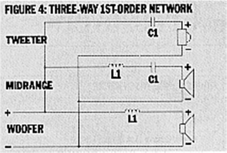
62 Filters Application: Speaker Crossover Networks You should remember: 1. A passive crossover requires no external power source to operate. 2. A passive crossover uses caps, coils and resistors to attenuate the signal level above and/or below a certain frequency. 3. Passive crossover networks are designed to pass selected frequencies to speaker drivers that acoustically reproduce those selected frequencies the most efficiently and accurately. - Speaker systems are designed as one-way, two-way, three-way, and four-way systems. The way means how many speaker drivers are connected together (usually in parallel) per channel output. - For example, a three-way speaker system contains a woofer driver, a midrange driver, and a tweeter driver. The woofer reproduces the low frequencies the best, the midrange the middle frequencies the best, and the tweeter the high frequencies the best for a given frequency range. It is the crossover network s job to make sure each speaker driver receives the range of frequencies it can most accurately and efficiently reproduce acoustically.
63 Filters Application: Speaker Crossover Networks You should remember: 4. Passive crossover networks are designed to pass selected frequencies to speaker drivers that acoustically reproduce those selected frequencies the most efficiently and accurately. Speaker systems are designed as one-way, two-way, three-way, and four-way systems. The way means how many speaker drivers are connected together (in parallel or series) per channel output. For example, a three-way speaker system contains a woofer driver, a midrange driver, and a tweeter driver. The woofer reproduces the low frequencies the best, the midrange the middle frequencies the best, and the tweeter the high frequencies the best for a given frequency range. It is the crossover network s job to make sure each speaker driver receives the range of frequencies it can most accurately and efficiently reproduce acoustically. Cut-off frequency guidelines; note that they are based on the use of 12-dB-per-octave slopes. SUBWOOFERS: Below 100 Hz (low-pass). WOOFERS/MIDBASSES: Between 100 and 500 Hz (low-pass or bandpass). MIDRANGES: Between 300 and 500 Hz (high-pass) and 3,500 and 8,000 Hz (low-pass) bandpass. TWEETERS: Above 5,000 Hz (high-pass). 5. In general, a high-pass filter with a slope of at least 12 db per octave should be used with midranges and tweeters, since this will protect them from potentially damaging low frequencies.

64 Filters Application: Speaker Crossover Networks Simple, one-way speaker systems. Most of the crossover networks shown are LC filters in Inverted-L and T configurations. For low and high pass LC filters, an L-C pair is two-poles or second order when the output voltage is taken across L or C. For bandpass or bandstop, an L-C filter pair is one-pole.
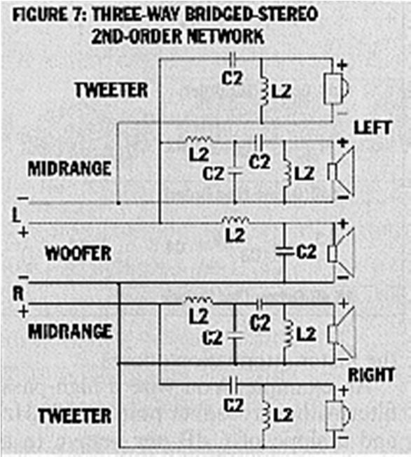
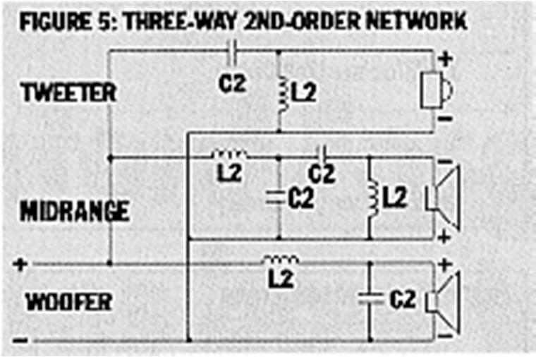
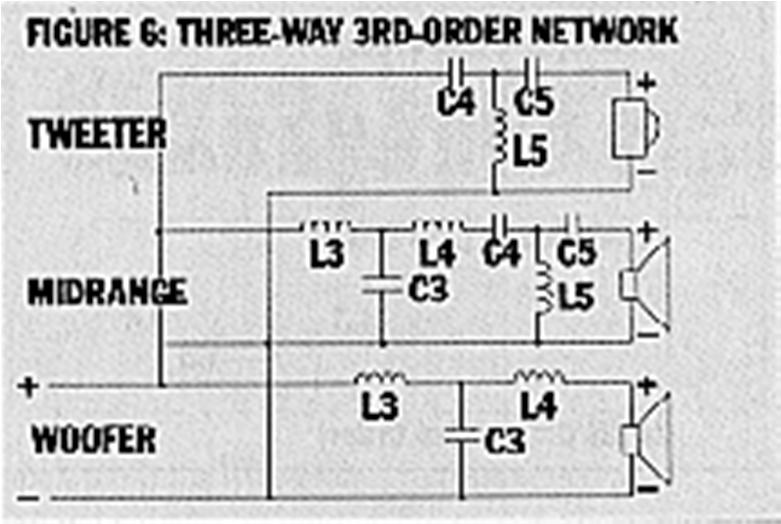
65 Filters Application: Speaker Crossover Networks
66 Filters Application: Speaker Crossover Networks


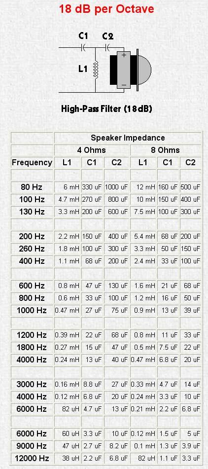
67 Passive Crossover Design Tables
68 Filters Application: Speaker Crossover Networks Passive High Pass Crossovers In the next four slides, there are 4 different crossover configurations. The graph shown after the 4 systems shows the slopes for -6dB (first order), -12dB (second order), -18dB (third order) and -24dB (fourth order) per octave crossovers. The crossover components' colors match its corresponding curve on the graph.

69 Passive High Pass Crossovers In this crossover, the capacitor blocks the lower frequencies while allowing the higher frequencies to pass. Roll-off Rate is -6dB/octave or -20dB/decade

70 Passive High Pass Crossovers In this crossover, the capacitor does the same thing as in the previous diagram. The inductor shunts, to ground, some of the low frequencies that are allowed to pass through the capacitor. This causes a higher roll off rate. Roll-off Rate is -12dB/octave or -40dB/decade
71 Passive High Pass Crossovers Roll-off Rate is -18dB/octave or -60dB/decade

72 Passive High Pass Crossovers Roll-off Rate is -24dB/octave or -80dB/decade

73 Passive High Pass Crossovers
74 Passive Low Pass Crossovers In the next four slides, there are 4 different crossover configurations. The graph shown after the 4 systems shows the slopes for -6dB (first order), -12dB (second order), -18dB (third order) and -24dB (fourth order) per octave crossovers. The crossover components' colors match its corresponding curve on the graph.

75 Passive Low Pass Crossovers In this crossover, the inductor blocks the higher frequencies while allowing the lower frequencies to pass. Roll-off Rate is -6dB/octave or -20dB/decade

76 Passive Low Pass Crossovers In this crossover, the inductor does the same thing as in the previous diagram. The capacitor shunts, to ground, some of the higher frequencies that are allowed to pass through the inductor. This causes a higher roll off rate. Roll-off Rate is -12dB/octave or -40dB/decade

77 Passive Low Pass Crossovers Roll-off Rate is -18dB/octave or -60dB/decade

78 Passive Low Pass Crossovers Roll-off Rate is -24dB/octave or -80dB/decade

79 Passive Low Pass Crossovers
80 Other Types of Crossover Networks Basics: When you double the cone area (add a second speaker with equal properties) while keeping the power constant, you gain 3dB of output. If you reduce the number of speakers by 1/2, you lose 3dB. If you double the power to a driver, you gain 3dB. If you cut the power by 1/2 you lose 3dB. If you double the cone area and the power (by paralleling the second speaker on the amplifier), you gain 6dB. The 'Q' of a filter (crossover) indicates the shape of the curve. For a second order crossover, it can be calculated with the formula: Q=[(R 2 C)/L] 1/2 Where R is the speaker's impedance. C is the capacitor used in the filter. And L is the inductor used in the filter.

81 Other Types of Crossover Networks Basics (continued): Acoustical Output & Power Whenever two loudspeakers are playing the same frequencies in phase, in the same location, there will be up to a 3 db rise in the acoustical output. When crossovers are used, both the low pass filtered loudspeaker and the high pass filtered loudspeaker are down by 3 db at the crossover frequency. Their combined output will be up to 3 db higher at the crossover point. The net result is neither a rise or fall in resistance to the amplifier or acoustical output at the crossover frequency as indicated by the yellow line between the low pass and high pass curves. This means if both loudspeakers are 4 ohm, the amplifier will see a 4 ohm load below, at, and above the crossover frequency (*excluding the natural impedance curves of the loudspeakers). The crossover not only separates the frequency ranges for the different loudspeakers in a speaker system, but also separates these frequency ranges and impedance (resistance) ranges for the amplifier.
82 2nd order Linkwitz-Riley In the following graph, you can see the response for both the high and low frequency drivers. You can also see that the crossover point is 150hz. As previously noted, the on-axis acoustic output of a L-R crossover has a flat response at the crossover frequency. To do this, the crossover point has to be 6 db down (2 nd -order). Since there are 2 drivers (a midrange and a woofer) operating at the crossover point and they presumably have a comparable output and they are receiving the same power (both 6dB down from full power), the output (their summed on-axis acoustic output) will be as if a single driver were playing at the crossover point. This will provide a flat overall frequency response at the crossover point.
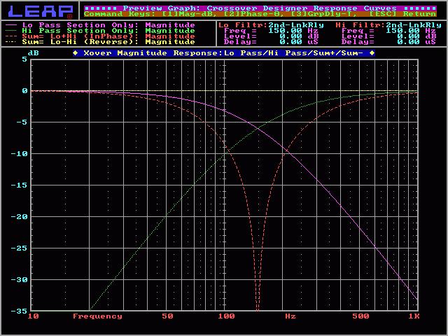
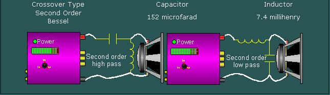
83
84 2nd order Bessel On the next graph, you'll see the response of a 2nd order Bessel crossover. You can see that the crossover point is 5dB down from the pass band. The summed response will give you a slight peak at the crossover point. The high pass and low pass curves have a Q of 0.58.
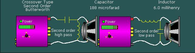
85
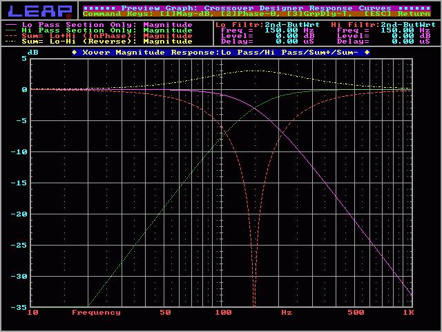
86 2nd order Butterworth On the next graph, you'll see the response of a 2nd order Butterworth crossover. The crossover point is 3dB down from the pass band. The summed response will give you a 3dB peak at the crossover point. The high pass and low pass curves have a Q of
87
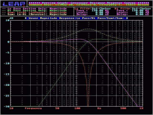
88 2nd order Chebychev On the next graph, you'll see the response of a 2nd order Chebychev crossover. The crossover point is at the same level as the pass band. The summed response will give you a 6dB peak at the crossover point. The high pass and low pass curves have a Q of 1.0.

89
, the circuit becomes a resonant circuit.")
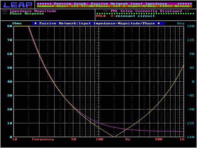
90 Open Crossover Output Warning You may damage your amplifier if you drive a second (or higher) order crossover when the speaker's voice coil is open (the speaker is blown) or if no speaker is connected to the crossover's output. When the speaker is removed (or the voice coil opens), the circuit becomes a resonant circuit. This circuit will, at the crossover frequency (or some multiple of the crossover frequency), present a 0 ohm load to the amplifier. The actual resistance will be only the resistance in the speaker wire and the inductor. Any time that there is audio at the resonant frequency, the amplifier will be stressed the same as if the speaker wires were shorted together. This will drive some amplifiers into protection. Others will blow a fuse or die a horrible painful death. The following graph shows how the impedance of the normal circuit (violet line) never drops below 4 ohms (the speaker's impedance). It also shows how the impedance of the circuit without a speaker (yellow line) drops to 0 ohms at the crossover frequency (for a 2nd order crossover, the resonant frequency is the same as the crossover frequency).
91
92 Summary In an RC low-pass filter, the output voltage is taken across the capacitor and the output lags the input. In an RL low-pass filter, the output voltage is taken across the resistor and the output lags the input. In an RC high-pass filter, the output is taken across the resistor and the output leads the input.
93 Summary In an RL high-pass filter, the output is taken across the inductor and the output leads the input. The roll-off rate of a basic RC or RL filter is -20 db per decade. A band-pass filter passes frequencies between the lower and upper critical frequencies and rejects all others.
94 Summary The bandwidth of a resonant filter is determined by the quality factor (Q) of the circuit and the resonant frequency. Critical frequencies are also called -3 db frequencies. The output voltage is 70.7% of its maximum at the critical frequencies.
A.C. FILTER NETWORKS. Learning Objectives
 C H A P T E 17 Learning Objectives Introduction Applications Different Types of Filters Octaves and Decades of Frequency Decibel System alue of 1 db Low-Pass C Filter Other Types of Low-Pass Filters Low-Pass
Low Pass Filter Introduction
 Low Pass Filter Introduction Basically, an electrical filter is a circuit that can be designed to modify, reshape or reject all unwanted frequencies of an electrical signal and accept or pass only those
EE301 ELECTRONIC CIRCUITS
 EE30 ELECTONIC CICUITS CHAPTE 5 : FILTES LECTUE : Engr. Muhammad Muizz Electrical Engineering Department Politeknik Kota Kinabalu, Sabah. 5. INTODUCTION Is a device that removes or filters unwanted signal.
Introduction (cont )
") Active Filter 1 Introduction Filters are circuits that are capable of passing signals within a band of frequencies while rejecting or blocking signals of frequencies outside this band. This property of
Active Filter 1 Introduction Filters are circuits that are capable of passing signals within a band of frequencies while rejecting or blocking signals of frequencies outside this band. This property of
FREQUENCY RESPONSE AND PASSIVE FILTERS LABORATORY
 FREQUENCY RESPONSE AND PASSIVE FILTERS LABORATORY In this experiment we will analytically determine and measure the frequency response of networks containing resistors, AC source/sources, and energy storage
π Speakers Crossover Electronics 101
 π Speakers Crossover Electronics 101 Overview 1. Resistors - Ohms Law Voltage Dividers and L-Pads 2. Reactive components - Inductors and Capacitors 3. Resonance 4. Peaking 5. Damping Formulas Ohm s Law
Chapter 2. The Fundamentals of Electronics: A Review
 Chapter 2 The Fundamentals of Electronics: A Review Topics Covered 2-1: Gain, Attenuation, and Decibels 2-2: Tuned Circuits 2-3: Filters 2-4: Fourier Theory 2-1: Gain, Attenuation, and Decibels Most circuits
PHYS225 Lecture 15. Electronic Circuits
 PHYS225 Lecture 15 Electronic Circuits Last lecture Difference amplifier Differential input; single output Good CMRR, accurate gain, moderate input impedance Instrumentation amplifier Differential input;
CHAPTER 14. Introduction to Frequency Selective Circuits
 CHAPTER 14 Introduction to Frequency Selective Circuits Frequency-selective circuits Varying source frequency on circuit voltages and currents. The result of this analysis is the frequency response of
EXPERIMENT 1: Characteristics of Passive and Active Filters
 Kathmandu University Department of Electrical and Electronics Engineering ELECTRONICS AND ANALOG FILTER DESIGN LAB EXPERIMENT : Characteristics of Passive and Active Filters Objective: To understand the
Assist Lecturer: Marwa Maki. Active Filters
 Active Filters In past lecture we noticed that the main disadvantage of Passive Filters is that the amplitude of the output signals is less than that of the input signals, i.e., the gain is never greater
Chapter 15: Active Filters
 Chapter 15: Active Filters 15.1: Basic filter Responses A filter is a circuit that passes certain frequencies and rejects or attenuates all others. The passband is the range of frequencies allowed to pass
Electric Circuit Theory
 Electric Circuit Theory Nam Ki Min nkmin@korea.ac.kr 010-9419-2320 Chapter 15 Active Filter Circuits Nam Ki Min nkmin@korea.ac.kr 010-9419-2320 Contents and Objectives 3 Chapter Contents 15.1 First-Order
Application Note 4. Analog Audio Passive Crossover
 Application Note 4 App Note Application Note 4 Highlights Importing Transducer Response Data Importing Transducer Impedance Data Conjugate Impedance Compensation Circuit Optimization n Design Objective
INTRODUCTION TO FILTER CIRCUITS
 INTRODUCTION TO FILTER CIRCUITS 1 2 Background: Filters may be classified as either digital or analog. Digital filters are implemented using a digital computer or special purpose digital hardware. Analog
Frequency Selective Circuits
 Lab 15 Frequency Selective Circuits Names Objectives in this lab you will Measure the frequency response of a circuit Determine the Q of a resonant circuit Build a filter and apply it to an audio signal
The above figure represents a two stage circuit. Recall, the transfer function relates. Vout
 LABORATORY 12: Bode plots/second Order Filters Material covered: Multistage circuits Bode plots Design problem Overview Notes: Two stage circuits: Vin1 H1(s) Vout1 Vin2 H2(s) Vout2 The above figure represents
Processor Setting Fundamentals -or- What Is the Crossover Point?
 The Law of Physics / The Art of Listening Processor Setting Fundamentals -or- What Is the Crossover Point? Nathan Butler Design Engineer, EAW There are many misconceptions about what a crossover is, and
Passive Crossovers MADE EASY
 Passive Crossovers MADE EASY MOBILE AUDIO INTERFACING EQUIPMENT A publication of Pacific Accessory Corporation Pacific Accessory Corporation 1502 S. Santa Fe Street, Santa Ana, CA 92705 www.go2pac.com
Filters occur so frequently in the instrumentation and
 FILTER Design CHAPTER 3 Filters occur so frequently in the instrumentation and communications industries that no book covering the field of RF circuit design could be complete without at least one chapter
Application Note 7. Digital Audio FIR Crossover. Highlights Importing Transducer Response Data FIR Window Functions FIR Approximation Methods
 Application Note 7 App Note Application Note 7 Highlights Importing Transducer Response Data FIR Window Functions FIR Approximation Methods n Design Objective 3-Way Active Crossover 200Hz/2kHz Crossover
Lecture 17 Date: Parallel Resonance Active and Passive Filters
 Lecture 17 Date: 09.10.2017 Parallel Resonance Active and Passive Filters Parallel Resonance At resonance: The voltage V as a function of frequency. At resonance, the parallel LC combination acts like
π Speakers P. O. Box Tulsa, OK (918)
") π Speakers P. O. Box 702006 Tulsa, OK 74170 (918) 663-2131 Speaker motors and passive crossover filters A study of the performance of loudspeakers in the presence of other reactive components Linear motor
π Speakers P. O. Box 702006 Tulsa, OK 74170 (918) 663-2131 Speaker motors and passive crossover filters A study of the performance of loudspeakers in the presence of other reactive components Linear motor
Filter Design, Active Filters & Review. EGR 220, Chapter 14.7, December 14, 2017
 Filter Design, Active Filters & Review EGR 220, Chapter 14.7, 14.11 December 14, 2017 Overview ² Passive filters (no op amps) ² Design examples ² Active filters (use op amps) ² Course review 2 Example:
Analog Filters D R. T A R E K T U T U N J I P H I L A D E L P H I A U N I V E R S I T Y, J O R D A N
 Analog Filters D. T A E K T U T U N J I P H I L A D E L P H I A U N I V E S I T Y, J O D A N 2 0 4 Introduction Electrical filters are deigned to eliminate unwanted frequencies Filters can be classified
An active filter offers the following advantages over a passive filter:
 ACTIVE FILTERS An electric filter is often a frequency-selective circuit that passes a specified band of frequencies and blocks or attenuates signals of frequencies outside this band. Filters may be classified
Operational Amplifiers
 Operational Amplifiers Continuing the discussion of Op Amps, the next step is filters. There are many different types of filters, including low pass, high pass and band pass. We will discuss each of the
How to Connect a Three-Way (Six Speaker) Legatia Speaker System to a 4-Channel Amplifier in a Quasi-Active Crossover Configuration
 Legatia Speaker System to a 4-Channel Amplifier in a Quasi-Active Crossover Configuration") How to Connect a Three-Way (Six Speaker) Legatia Speaker System to a 4-Channel Amplifier in a Quasi-Active Crossover Configuration Hybrid Audio Technologies highly recommends the use of active crossovers
How to Connect a Three-Way (Six Speaker) Legatia Speaker System to a 4-Channel Amplifier in a Quasi-Active Crossover Configuration Hybrid Audio Technologies highly recommends the use of active crossovers
3 Analog filters. 3.1 Analog filter characteristics
 Chapter 3, page 1 of 11 3 Analog filters This chapter deals with analog filters and the filter approximations of an ideal filter. The filter approximations that are considered are the classical analog
Lab 1: Basic RL and RC DC Circuits
 Name- Surname: ID: Department: Lab 1: Basic RL and RC DC Circuits Objective In this exercise, the DC steady state response of simple RL and RC circuits is examined. The transient behavior of RC circuits
Active Filter Design Techniques
 Active Filter Design Techniques 16.1 Introduction What is a filter? A filter is a device that passes electric signals at certain frequencies or frequency ranges while preventing the passage of others.
EK307 Active Filters and Steady State Frequency Response
 EK307 Active Filters and Steady State Frequency Response Laboratory Goal: To explore the properties of active signal-processing filters Learning Objectives: Active Filters, Op-Amp Filters, Bode plots Suggested
Electronic PRINCIPLES
 MALVINO & BATES Electronic PRINCIPLES SEVENTH EDITION Chapter 21 Active Filters Topics Covered in Chapter 21 Ideal responses Approximate responses Passive ilters First-order stages VCVS unity-gain second-order
9 A small tutorial. 9.1 Loudspeaker boxes
 9 A small tutorial This section is a very small tutorial about different aspects of loudspeaker construction. As explained before the intention is not to explain everything. Instead the idea is to only
Active Filter. Low pass filter High pass filter Band pass filter Band stop filter
 Active Filter Low pass filter High pass filter Band pass filter Band stop filter Active Low-Pass Filters Basic Low-Pass filter circuit At critical frequency, esistance capacitance X c ω c πf c So, critical
Pre-Lab. Introduction
 Pre-Lab Read through this entire lab. Perform all of your calculations (calculated values) prior to making the required circuit measurements. You may need to measure circuit component values to obtain
Advanced Measurements
 Albaha University Faculty of Engineering Mechanical Engineering Department Lecture 9: Wheatstone Bridge and Filters Ossama Abouelatta o_abouelatta@yahoo.com Mechanical Engineering Department Faculty of
EE-2302 Passive Filters and Frequency Response
 EE2302 Passive Filters and Frequency esponse Objective he student should become acquainted with simple passive filters for performing highpass, lowpass, and bandpass operations. he experimental tasks also
SEEBURG acoustic line. active systempanel 2. owner s manual
 SEEBURG acoustic line active systempanel 2 owner s manual TABLE OF CONTENTS 1 INTRODUCTION 1 1.1 How to use this manual 2 2 THE CONTROLS AND CONNECTORS 2 3 OPERATING THE SP2 4 3.1 Active frequency dividing
Kent Bertilsson Muhammad Amir Yousaf
 Today s topics Analog System (Rev) Frequency Domain Signals in Frequency domain Frequency analysis of signals and systems Transfer Function Basic elements: R, C, L Filters RC Filters jw method (Complex
Electrical Circuits II (ECE233b)
") Electrical ircuits II (EE33b) ariablefrequency Network Performance (Part 3) Anestis Dounavis The University of Western Ontario Faculty of Engineering Science Scaling Often the values of circuit parameters
Electrical ircuits II (EE33b) ariablefrequency Network Performance (Part 3) Anestis Dounavis The University of Western Ontario Faculty of Engineering Science Scaling Often the values of circuit parameters
ITT Technical Institute ET245 Devices II Unit 5 Chapter
 ITT Technical Institute ET245 Devices II Unit 5 Chapter 7.1 7.3 Unit 5 Agenda Lecture: Chapter 7, Sections 7.1 7.3 Lab 3, Linear Op amp Circuits continued from last week Assignment: Complete Problems (pg
Stereo 3-Way Active Crossover User Manual Model K231 Sublime Acoustic, LLC
 Stereo 3-Way Active Crossover User Manual Model K231 Sublime Acoustic, LLC Features Stereo 3-way Active Crossover for driving separate subwoofer, midrange and tweeter amplifiers Linkwitz-Riley crossover
RaneNote 119 LINKWITZ-RILEY ACTIVE CROSSOVERS UP TO 8TH- ORDER: AN OVERVIEW
 RaneNote 119 Filter Fundamentals LRC & Gyrator Equalizers Parametric Equalizers Constant-Q Equalizers Interpolating Constant-Q Equalizers Dennis Bohn Rane Corporation LINKWITZ-RILEY ACTIVE CROSSOVERS UP
Analog Design-filters
 Analog Design-filters Introduction and Motivation Filters are networks that process signals in a frequency-dependent manner. The basic concept of a filter can be explained by examining the frequency dependent
Butterworth Active Bandpass Filter using Sallen-Key Topology
 Butterworth Active Bandpass Filter using Sallen-Key Topology Technical Report 5 Milwaukee School of Engineering ET-3100 Electronic Circuit Design Submitted By: Alex Kremnitzer Date: 05-11-2011 Date Performed:
Lab 9: Operational amplifiers II (version 1.5)
") Lab 9: Operational amplifiers II (version 1.5) WARNING: Use electrical test equipment with care! Always double-check connections before applying power. Look for short circuits, which can quickly destroy
Lab 9: Operational amplifiers II (version 1.5) WARNING: Use electrical test equipment with care! Always double-check connections before applying power. Look for short circuits, which can quickly destroy
Analog Electronics. Lecture. Op-amp Circuits and Active Filters. Muhammad Amir Yousaf
 Analog Electronics Lecture Op-amp Circuits and Active Filters Muhammad Amir Yousaf Instrumentation Amplifiers An instrumentation amplifier (IA) amplifies the voltage difference between its terminals. It
Lab 9 Frequency Domain
 Lab 9 Frequency Domain 1 Components Required Resistors Capacitors Function Generator Multimeter Oscilloscope 2 Filter Design Filters are electric components that allow applying different operations to
CHAPTER 6 Frequency Response, Bode. Plots, and Resonance
 CHAPTER 6 Frequency Response, Bode Plots, and Resonance CHAPTER 6 Frequency Response, Bode Plots, and Resonance 1. State the fundamental concepts of Fourier analysis. 2. Determine the output of a filter
EE233 Autumn 2016 Electrical Engineering University of Washington. EE233 HW7 Solution. Nov. 16 th. Due Date: Nov. 23 rd
 EE233 HW7 Solution Nov. 16 th Due Date: Nov. 23 rd 1. Use a 500nF capacitor to design a low pass passive filter with a cutoff frequency of 50 krad/s. (a) Specify the cutoff frequency in hertz. fc c 50000
Resonance. Resonance curve.
 Resonance This chapter will introduce the very important resonant (or tuned) circuit, which is fundamental to the operation of a wide variety of electrical and electronic systems in use today. The resonant
LCR Parallel Circuits
 Module 10 AC Theory Introduction to What you'll learn in Module 10. The LCR Parallel Circuit. Module 10.1 Ideal Parallel Circuits. Recognise ideal LCR parallel circuits and describe the effects of internal
v(t) = V p sin(2π ft +φ) = V p cos(2π ft +φ + π 2 )
 = V p sin(2π ft +φ) = V p cos(2π ft +φ + π 2 )") 1 Let us revisit sine and cosine waves. A sine wave can be completely defined with three parameters Vp, the peak voltage (or amplitude), its frequency w in radians/second or f in cycles/second (Hz), and
1 Let us revisit sine and cosine waves. A sine wave can be completely defined with three parameters Vp, the peak voltage (or amplitude), its frequency w in radians/second or f in cycles/second (Hz), and
Application Note 5. Analog Audio Active Crossover
 App Note Highlights Importing Transducer Response Data Generic Transfer Function Modeling Circuit Optimization Cascade Circuit Synthesis n Design Objective 3-Way Active Crossover 4th Order Crossover 200Hz/2kHz
Kerwin, W.J. Passive Signal Processing The Electrical Engineering Handbook Ed. Richard C. Dorf Boca Raton: CRC Press LLC, 2000
 Kerwin, W.J. Passive Signal Processing The Electrical Engineering Handbook Ed. Richard C. Dorf Boca Raton: CRC Press LLC, 000 4 Passive Signal Processing William J. Kerwin University of Arizona 4. Introduction
APPENDIX A to VOLUME A1 TIMS FILTER RESPONSES
 APPENDIX A to VOLUME A1 TIMS FILTER RESPONSES A2 TABLE OF CONTENTS... 5 Filter Specifications... 7 3 khz LPF (within the HEADPHONE AMPLIFIER)... 8 TUNEABLE LPF... 9 BASEBAND CHANNEL FILTERS - #2 Butterworth
Passive Crossovers MADE EASY. Pre-made Crossovers. Mobile Audio Interfacing Equipment $9.95
 Premade Crossovers $9.95 Competition and super deluxe systems are nice to do. This is particularly true when a lot of special crossovers are designed with different ohm loads in the various frequency sections.
3-Way Active Crossover Model XOVER-3. Xkitz.com. User s Manual. Features. Rev 2.1
 3-Way Active Crossover Model XOVER-3 User s Manual Rev 2.1 Xkitz.com Features 3-way Active Crossover for driving separate subwoofer, midrange and tweeter amplifiers Linkwitz-Riley crossover, 4 th order,
Active Filters - Revisited
 Active Filters - Revisited Sources: Electronic Devices by Thomas L. Floyd. & Electronic Devices and Circuit Theory by Robert L. Boylestad, Louis Nashelsky Ideal and Practical Filters Ideal and Practical
The Mimir. Enclosure and stuffing. Drive units
 The Mimir Named after Mimir, a primal god of Norse mythology who was renowned for his knowledge and wisdom, we present a new high-end two-way speaker kit. The Mimir consist of an 18 cm long throw woofer
Experiment 9 AC Circuits
 Experiment 9 AC Circuits "Look for knowledge not in books but in things themselves." W. Gilbert (1540-1603) OBJECTIVES To study some circuit elements and a simple AC circuit. THEORY All useful circuits
ONLINE TUTORIALS. Log on using your username & password. (same as your ) Choose a category from menu. (ie: audio)
 Choose a category from menu. (ie: audio)") ONLINE TUTORIALS Go to http://uacbt.arizona.edu Log on using your username & password. (same as your email) Choose a category from menu. (ie: audio) Choose what application. Choose which tutorial movie.
ONLINE TUTORIALS Go to http://uacbt.arizona.edu Log on using your username & password. (same as your email) Choose a category from menu. (ie: audio) Choose what application. Choose which tutorial movie.
Core Technology Group Application Note 6 AN-6
 Characterization of an RLC Low pass Filter John F. Iannuzzi Introduction Inductor-capacitor low pass filters are utilized in systems such as audio amplifiers, speaker crossover circuits and switching power
FIRST WATT B4 USER MANUAL
 FIRST WATT B4 USER MANUAL 6/23/2012 Nelson Pass Introduction The B4 is a stereo active crossover filter system designed for high performance and high flexibility. It is intended for those who feel the
EKT 356 MICROWAVE COMMUNICATIONS CHAPTER 4: MICROWAVE FILTERS
 EKT 356 MICROWAVE COMMUNICATIONS CHAPTER 4: MICROWAVE FILTERS 1 INTRODUCTION What is a Microwave filter? linear 2-port network controls the frequency response at a certain point in a microwave system provides
Tapped Inductor Bandpass Filter Design. High Speed Signal Path Applications 7/21/2009 v1.6
 Tapped Inductor Bandpass Filter Design High Speed Signal Path Applications 7/1/009 v1.6 Tapped Inductor BP Filter 1 st order (6 db/oct) LOW frequency roll-off Shunt LT 4 th order (4 db/oct) HIGH frequency
High-Performance Audio Applications of The LM833
 High-Performance Audio Applications of The LM833 Designers of quality audio equipment have long recognized the value of a low noise gain block with audiophile performance. The LM833 is such a device: a
Quadra 15 Available in Black and White
 S P E C I F I C A T I O N S Quadra 15 Available in Black and White Frequency response, 1 meter onaxis, swept-sine in anechoic environment: 64 Hz to 18 khz (±3 db) Usable low frequency limit (-10 db point):
2-Way Active Crossover Model XOVER-2. Xkitz.com. User s Manual. Features. Rev 5.0
 2-Way Active Crossover Model XOVER-2 User s Manual Rev 5.0 Xkitz.com Features 2-way Active Crossover for driving separate woofer and tweeter amplifiers Linkwitz-Riley crossover, 4 th order, 24dB/Octave
Outcomes: Core Competencies for ECE145A/218A
 Outcomes: Core Competencies for ECE145A/18A 1. Transmission Lines and Lumped Components 1. Use S parameters and the Smith Chart for design of lumped element and distributed L matching networks. Able to
Review of Filter Types
 ECE 440 FILTERS Review of Filters Filters are systems with amplitude and phase response that depends on frequency. Filters named by amplitude attenuation with relation to a transition or cutoff frequency.
AC Measurements with the Agilent 54622D Oscilloscope
 AC Measurements with the Agilent 54622D Oscilloscope Objectives: At the end of this experiment you will be able to do the following: 1. Correctly configure the 54622D for measurement of voltages. 2. Perform
An active filters means using amplifiers to improve the filter. An acive second-order RC low-pass filter still has two RC components in series.
 Active Filters An active filters means using amplifiers to improve the filter. An acive second-order low-pass filter still has two components in series. Hjω ( ) -------------------------- 2 = = ----------------------------------------------------------
Quadra 10 Available in Black and White
 S P E C I F I C A T I O N S Quadra 10 Available in Black and White Frequency response, 1 meter on-axis, swept-sine in anechoic environment: 74 Hz 18 khz (±3 db) Usable low frequency limit (-10 db point):
Chapter 31. Alternating Current. PowerPoint Lectures for University Physics, 14th Edition Hugh D. Young and Roger A. Freedman Lectures by Jason Harlow
 Chapter 31 Alternating Current PowerPoint Lectures for University Physics, 14th Edition Hugh D. Young and Roger A. Freedman Lectures by Jason Harlow Learning Goals for Chapter 31 Looking forward at How
CHAPTER 8 ANALOG FILTERS
 ANALOG FILTERS CHAPTER 8 ANALOG FILTERS SECTION 8.: INTRODUCTION 8. SECTION 8.2: THE TRANSFER FUNCTION 8.5 THE SPLANE 8.5 F O and Q 8.7 HIGHPASS FILTER 8.8 BANDPASS FILTER 8.9 BANDREJECT (NOTCH) FILTER
AC Circuits. "Look for knowledge not in books but in things themselves." W. Gilbert ( )
") AC Circuits "Look for knowledge not in books but in things themselves." W. Gilbert (1540-1603) OBJECTIVES To study some circuit elements and a simple AC circuit. THEORY All useful circuits use varying
AC Circuits "Look for knowledge not in books but in things themselves." W. Gilbert (1540-1603) OBJECTIVES To study some circuit elements and a simple AC circuit. THEORY All useful circuits use varying
EE 230 Lab Lab nf C 2. A. Low-Q low-pass active filters. (a) 10 k! Figure 1. (a) First-order low-pass. (b) Second-order low-pass.
 10 k! Figure 1. (a) First-order low-pass. (b) Second-order low-pass.") Second-order filter circuits This time, we measure frequency response plots for second-order filters. We start by examining a simple 2nd-order low-pass filter. The we look at the various arrangements of
Second-order filter circuits This time, we measure frequency response plots for second-order filters. We start by examining a simple 2nd-order low-pass filter. The we look at the various arrangements of
EXPERIMENT NUMBER 8 Introduction to Active Filters
 EXPERIMENT NUMBER 8 Introduction to Active Filters i-1 Preface: Preliminary exercises are to be done and submitted individually. Laboratory hardware exercises are to be done in groups. This laboratory
Filter Notes. You may have memorized a formula for the voltage divider - if not, it is easily derived using Ohm's law, Vo Vi
 Filter Notes You may have memorized a formula for the voltage divider - if not, it is easily derived using Ohm's law, Vo Vi R2 R+ R2 If you recall the formula for capacitive reactance, the divider formula
App Note Highlights Importing Transducer Response Data Generic Transfer Function Modeling Circuit Optimization Digital IIR Transform IIR Z Root Editor
 Application Note 6 App Note Application Note 6 Highlights Importing Transducer Response Data Generic Transfer Function Modeling Circuit Optimization Digital IIR Transform IIR Z Root Editor n Design Objective
The Five-Minute Filter University, July Session
 The Five-Minute Filter University, July Session Jul 1, 2006 By: Ed Ramsden Sensors Magazine http://process.sensorsmag.com/ What Filters Do Back in the late 1970s comedian Don Novello (a.k.a. Father Guido
Lecture 16 Date: Frequency Response (Contd.)
") Lecture 16 Date: 03.10.2017 Frequency Response (Contd.) Bode Plot (contd.) Bode Plot (contd.) Bode Plot (contd.) not every transfer function has all seven factors. To sketch the Bode plots for a generic
Lecture 16 Date: 03.10.2017 Frequency Response (Contd.) Bode Plot (contd.) Bode Plot (contd.) Bode Plot (contd.) not every transfer function has all seven factors. To sketch the Bode plots for a generic
EXPERIMENT 4: RC, RL and RD CIRCUITs
 EXPERIMENT 4: RC, RL and RD CIRCUITs Equipment List Resistor, one each of o 330 o 1k o 1.5k o 10k o 100k o 1000k 0.F Ceramic Capacitor 4700H Inductor LED and 1N4004 Diode. Introduction We have studied
ActiveLowPassFilter -- Overview
 ActiveLowPassFilter -- Overview OBJECTIVES: At the end of performing this experiment, learners would be able to: Describe the concept of active Low Pass Butterworth Filter Obtain the roll-off factor and
Bandpass Filters Using Capacitively Coupled Series Resonators
 8.8 Filters Using Coupled Resonators 441 B 1 B B 3 B N + 1 1 3 N (a) jb 1 1 jb jb 3 jb N jb N + 1 N (b) 1 jb 1 1 jb N + 1 jb N + 1 N + 1 (c) J 1 J J Z N + 1 0 Z +90 0 Z +90 0 Z +90 0 (d) FIGURE 8.50 Development
The G4EGQ RAE Course Lesson 4A AC theory
 AC. CIRCUITS This lesson introduces inductors into our AC. circuit. We then look at the result of having various combinations of capacitance, inductance and resistance in the same circuit. This leads us
PHYS 3322 Modern Laboratory Methods I AC R, RC, and RL Circuits
 Purpose PHYS 3322 Modern Laboratory Methods I AC, C, and L Circuits For a given frequency, doubling of the applied voltage to resistors, capacitors, and inductors doubles the current. Hence, each of these
ECE 203 LAB 2 PRACTICAL FILTER DESIGN & IMPLEMENTATION
 Version 1. 1 of 7 ECE 03 LAB PRACTICAL FILTER DESIGN & IMPLEMENTATION BEFORE YOU BEGIN PREREQUISITE LABS ECE 01 Labs ECE 0 Advanced MATLAB ECE 03 MATLAB Signals & Systems EXPECTED KNOWLEDGE Understanding
Filters and Tuned Amplifiers
 CHAPTER 6 Filters and Tuned Amplifiers Introduction 55 6. Filter Transmission, Types, and Specification 56 6. The Filter Transfer Function 60 6.7 Second-Order Active Filters Based on the Two-Integrator-Loop
Crossover Design by Software
 ALMA Europe 2009 Paper Presentation: Crossover Design by Software Peter Larsen The Purpose of the Crossover: 1. Protect midrange and tweeter from LF overload 2. Obtain smooth transition between drivers
Testing and Stabilizing Feedback Loops in Today s Power Supplies
 Keywords Venable, frequency response analyzer, impedance, injection transformer, oscillator, feedback loop, Bode Plot, power supply design, open loop transfer function, voltage loop gain, error amplifier,
+ + G c (s G p (s. a) What is overall transfer closed-loop transfer function θ(s)
 What is overall transfer closed-loop transfer function θ(s)") Problem 1 (35 pts) Department of Mechanical Engineering Massachusetts Institute of Technology 2.14 Analysis and Design of Feedback Control Systems Fall 2004 Quiz 1 Wednesday October 6, 2004 OPEN BOOK A
Problem 1 (35 pts) Department of Mechanical Engineering Massachusetts Institute of Technology 2.14 Analysis and Design of Feedback Control Systems Fall 2004 Quiz 1 Wednesday October 6, 2004 OPEN BOOK A
Introduction to Signals, Passive RC Filters and Opamps
 Introduction to Signals, ive RC Filters and Opamps LB Introduction In this laboratory exercise you design, build and test some simple filter circuits. his is mainly for you to get comfortable with circuit
Quadra 12 Available in Black and White
 S P E C I F I C A T I O N S Quadra 12 Available in Black and White Frequency response, 1 meter onaxis, swept-sine in anechoic environment: 76 Hz to 18 khz (±3 db) Usable low frequency limit (-10 db point):
Third Year (Electrical & Telecommunication Engineering)
") Z PRACTICAL WORK BOOK For The Course EE-315 Electric Filter For Third Year (Electrical & Telecommunication Engineering) Name of Student: Class: Batch : Discipline: Class Roll No.: Examination Seat No.
Z PRACTICAL WORK BOOK For The Course EE-315 Electric Filter For Third Year (Electrical & Telecommunication Engineering) Name of Student: Class: Batch : Discipline: Class Roll No.: Examination Seat No.
Input Filter Design for Switching Power Supplies Michele Sclocchi Application Engineer National Semiconductor
 Input Filter Design for Switching Power Supplies Michele Sclocchi Application Engineer National Semiconductor The design of a switching power supply has always been considered a kind of magic and art,
Audio Applications for Op-Amps, Part III By Bruce Carter Advanced Analog Products, Op Amp Applications Texas Instruments Incorporated
 Audio Applications for OpAmps, Part III By Bruce Carter Advanced Analog Products, Op Amp Applications Texas Instruments Incorporated This is the third in a series of articles on singlesupply audio circuits.
C7: Speaker Components
 Reference this. 2 C7: Speaker Components The C7 project was directed by JL Audio s Chief Engineer and CEO, Lucio Proni, with a clear mission to create our finest-ever automotive component speakers. Challenging