Filter Notes. You may have memorized a formula for the voltage divider - if not, it is easily derived using Ohm's law, Vo Vi
|
|
|
- Leon Lee
- 6 years ago
- Views:
Transcription
1 Filter Notes You may have memorized a formula for the voltage divider - if not, it is easily derived using Ohm's law, Vo Vi R2 R+ R2 If you recall the formula for capacitive reactance, the divider formula works fine when R2 is replaced by a capacitor. j Vo 2π fc Vi + j2π frc R j 2π fc This is the formula for the transfer function of an elementary low pass filter. Consider two frequency ranges:. Very low frequencies ( f 0) Vo Vi + 0 Flat response - no change in amplitude and no phase shift. 2. Very high frequencies (denominator dominated by second term) Vo Vi j2π frc Amplitude dropping like /f - phase shift of -90 We define a frequency midway between these two extreme ranges, f f C. The cutoff frequency is that frequency at which Vo Vi + j Vo * Vi - phase shift is -45 So 2πf C RC, and f C 2π RC
2 Filter Prep. Sketch what you expect for "Signal + Noise" for both cases. Time domain - Amplitude say from -.2 volts to +.2 volts and time from 0-00 milliseconds. Frequency domain - Amplitude arbitrary and frequency from 0Hz to 0KHz (logarithmic). 2. Characterize the noises - can you associate one case with additive jitter (static) and the other with drift?. Which is which? 3. Recall filters from ac circuits - draw circuit diagrams for high pass and low pass RC filters. Choose resistors and capacitors to realize ) low pass with fc 500Hz, and 2) high pass with fc 20Hz. What is the order of these filters? If these analog filters were used on our two cases, how much improvement in signal/noise ratio should we expect? What order digital filter shall we use in LabView? Solution: The elemental RC filters have similar forms The formula for cutoff frequency is the same, f C /(2πRC). Choose a plentiful C, say C 0. μf. So, R /(2πf C C) and I get: Low pass - fc 500Hz - R 3,85 Ohms (Use a 3.2K), and High pass - fc 20Hz - R 79,68 Ohms (Use an 80K). These are both first order filters - Response in the stop band is rolling off at -20 db/decade or -6 db/octave. For both filters the cutoff frequency is one octave away from the noise - therefore the noise would be smashed by a factor of 2. Expect the 0. volt noise amplitudes to be reduced to 0.05 volts - a 6 db improvement in S/N ratio in both cases. In LabView let's specify sixth order filters (no problem if we allow plenty of taps - filter length at least 30). We would expect noise attenuation of 20 db/ decade or 36 db/octave. With our one octave separation we would expect to smash the noise by a factor of 64. The 0. volt noise amplitudes should be reduced to about volts - a 36 db improvement in S/N ratio in both cases
3 Design of Butterworth Filters An example of pole placement using op amps
4 What in the World are Poles? Circuit designers use pole location in the complex frequency plane as an indication of expected circuit performance. Poles are the (perhaps complex) roots of the denominator of the circuit s transfer function, V o /E i. The Butterworth filter response and the Tchebyscheff filter response are among the most popular, physically realizable approximations to the ideal low pass filter. The Butterworth response is defined in terms of the location of its poles in the complex plane. We will concentrate on the Butterworth response, but learn to pronounce and spell Tchebyscheff. It s even more impressive than Kirchhoff.

5 Approximations to an ideal low pass filter

6 Circuit s Transfer Function squared, Vo / Ei 2

7 Poles of F 2 in the Complex Frequency Plane
8 Let us show that the low pass filters in Chapter are truly Butterworth. The authors of your text give us the transfer function (equation -b) for the -20 db/decade filter shown as figure -2a. A F(j ω) CL + jω RC In order to be Butterworth, the poles of F(jω) F(-jω) must divide the circle into equal arcs while avoiding the imaginary axis (2 o clock). Let s just look at the poles of F(jω) in the left half plane. The -20 db/decade filter clearly has one real pole at jω - /(RC). The circle is divided equally (two 80 arcs) while avoiding the imaginary axis. The filter is Butterworth, and its cutoff frequency is at ω c /(RC). This might be called a first order or a one pole Butterworth..
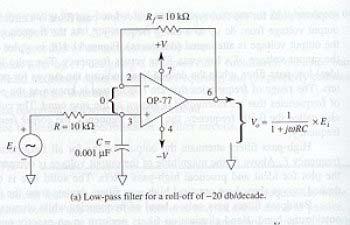
9
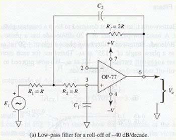
10 The authors of your text don t give us the transfer function for the -40 db/decade filter shown as figure -4a. It is fairly easy to show that: A F(j ω) CL j 2ωRC + (j ω) R CC By the quadratic formula, we see that the roots of the denominator are at: 2 roots at ± RC 2 C C RC 2 2 Our -40 db/decade filter recipe calls for C 2 2 C ; so our two complex poles are at (-+j) / (RC 2 ) and (--j) / (RC 2 ). In polar form, the poles are at.44 / (RC 2 ) 35 and.44 / (RC 2 ) 225. The circle is divided equally (four 90 arcs). The filter is Butterworth, and its cutoff frequency is at ω c.44 / (RC 2 ). or ω c.707/ (RC ) This might be called a second order or a two pole Butterworth.
11 The -60 db/decade filter introduces the idea of cascading stages in order to introduce more poles. The -20 db/decade stage places a negative real pole at -/RC 3. The -40 db/decade stage again places a complex pair of poles according to: roots at ± RC 2 C C RC 2 2 This time a different recipe is required: C /2 C 3 and C 2 2 C 3. Now the roots are at (-+j 3) /(RC 2 ) and (--j 3) /(RC 2 ). In polar form (and in terms of C 3 ) the poles are at /(RC 3 ) 20 and /(RC 3 ) 240 The circle is divided equally (six 60 arcs). The filter is Butterworth, and its cutoff frequency is at ω c /(RC 3 ) This might be called a third order or a three pole Butterworth.
12 A Butterworth Summary The Butterworth response is popular because it is so transparent to data in the passband. The amplitude response is as flat as possible, and the phase response is very gentle as well. The Butterworth response is realized by placing poles - at equal spacing - on a circle in the complex frequency plane. The filters in Chapter are indeed Butterworth. We could generalize the procedure, and design Butterworth filters of higher order. Just place poles where they need to be. We could generalize the procedure, and design most any circuit that was defined in term of pole location.
Review of Filter Types
 ECE 440 FILTERS Review of Filters Filters are systems with amplitude and phase response that depends on frequency. Filters named by amplitude attenuation with relation to a transition or cutoff frequency.
EXPERIMENT 1: Characteristics of Passive and Active Filters
 Kathmandu University Department of Electrical and Electronics Engineering ELECTRONICS AND ANALOG FILTER DESIGN LAB EXPERIMENT : Characteristics of Passive and Active Filters Objective: To understand the
Introduction (cont )
") Active Filter 1 Introduction Filters are circuits that are capable of passing signals within a band of frequencies while rejecting or blocking signals of frequencies outside this band. This property of
Active Filter 1 Introduction Filters are circuits that are capable of passing signals within a band of frequencies while rejecting or blocking signals of frequencies outside this band. This property of
Operational Amplifiers
 Operational Amplifiers Continuing the discussion of Op Amps, the next step is filters. There are many different types of filters, including low pass, high pass and band pass. We will discuss each of the
Chapter 15: Active Filters
 Chapter 15: Active Filters 15.1: Basic filter Responses A filter is a circuit that passes certain frequencies and rejects or attenuates all others. The passband is the range of frequencies allowed to pass
Active Filters - Revisited
 Active Filters - Revisited Sources: Electronic Devices by Thomas L. Floyd. & Electronic Devices and Circuit Theory by Robert L. Boylestad, Louis Nashelsky Ideal and Practical Filters Ideal and Practical
Active Filter. Low pass filter High pass filter Band pass filter Band stop filter
 Active Filter Low pass filter High pass filter Band pass filter Band stop filter Active Low-Pass Filters Basic Low-Pass filter circuit At critical frequency, esistance capacitance X c ω c πf c So, critical
Lecture 8: More on Operational Amplifiers (Op Amps)
") Lecture 8: More on Operational mplifiers (Op mps) Input Impedance of Op mps and Op mps Using Negative Feedback: Consider a general feedback circuit as shown. ssume that the amplifier has input impedance
Lecture 8: More on Operational mplifiers (Op mps) Input Impedance of Op mps and Op mps Using Negative Feedback: Consider a general feedback circuit as shown. ssume that the amplifier has input impedance
Exercise 2: High-Pass Filters
 Exercise 2: High-Pass Filters EXERCISE OBJECTIVE When you have completed this exercise, you will be able to calculate and measure the cutoff frequencies oscilloscope. DISCUSSION of inductors, capacitors,
3 Analog filters. 3.1 Analog filter characteristics
 Chapter 3, page 1 of 11 3 Analog filters This chapter deals with analog filters and the filter approximations of an ideal filter. The filter approximations that are considered are the classical analog
University of Michigan EECS 311: Electronic Circuits Fall 2008 LAB 2 ACTIVE FILTERS
 University of Michigan EECS 311: Electronic Circuits Fall 2008 LAB 2 ACTIVE FILTERS Issued 9/22/2008 Pre Lab Completed 9/29/2008 Lab Due in Lecture 10/6/2008 Introduction In this lab you will design a
PHYS 536 Active Filters
 PHYS 536 Active Filters Introduction Active filters provide a sudden change in signal amplitude for a small change in frequency. Several filters can be used in series to increase the attenuation outside
NH 67, Karur Trichy Highways, Puliyur C.F, Karur District DEPARTMENT OF INFORMATION TECHNOLOGY DIGITAL SIGNAL PROCESSING UNIT 3
 NH 67, Karur Trichy Highways, Puliyur C.F, 639 114 Karur District DEPARTMENT OF INFORMATION TECHNOLOGY DIGITAL SIGNAL PROCESSING UNIT 3 IIR FILTER DESIGN Structure of IIR System design of Discrete time
Basic Analog Circuits
 Basic Analog Circuits Overview This tutorial is part of the National Instruments Measurement Fundamentals series. Each tutorial in this series, will teach you a specific topic of common measurement applications,
ActiveLowPassFilter -- Overview
 ActiveLowPassFilter -- Overview OBJECTIVES: At the end of performing this experiment, learners would be able to: Describe the concept of active Low Pass Butterworth Filter Obtain the roll-off factor and
Electric Circuit Theory
 Electric Circuit Theory Nam Ki Min nkmin@korea.ac.kr 010-9419-2320 Chapter 15 Active Filter Circuits Nam Ki Min nkmin@korea.ac.kr 010-9419-2320 Contents and Objectives 3 Chapter Contents 15.1 First-Order
Comparison of Signal Attenuation of Multiple Frequencies Between Passive and Active High-Pass Filters
 Comparison of Signal Attenuation of Multiple Frequencies Between Passive and Active High-Pass Filters Aaron Batker Pritzker Harvey Mudd College 23 November 203 Abstract Differences in behavior at different
1) Consider the circuit shown in figure below. Compute the output waveform for an input of 5kHz
 Consider the circuit shown in figure below. Compute the output waveform for an input of 5kHz") ) Consider the circuit shown in figure below. Compute the output waveform for an input of 5kHz Solution: a) Input is of constant amplitude of 2 V from 0 to 0. ms and 2 V from 0. ms to 0.2 ms. The output
) Consider the circuit shown in figure below. Compute the output waveform for an input of 5kHz Solution: a) Input is of constant amplitude of 2 V from 0 to 0. ms and 2 V from 0. ms to 0.2 ms. The output
Analog Electronics. Lecture. Op-amp Circuits and Active Filters. Muhammad Amir Yousaf
 Analog Electronics Lecture Op-amp Circuits and Active Filters Muhammad Amir Yousaf Instrumentation Amplifiers An instrumentation amplifier (IA) amplifies the voltage difference between its terminals. It
EXPERIMENT 4: RC, RL and RD CIRCUITs
 EXPERIMENT 4: RC, RL and RD CIRCUITs Equipment List An assortment of resistor, one each of (330, 1k,1.5k, 10k,100k,1000k) Function Generator Oscilloscope 0.F Ceramic Capacitor 100H Inductor LED and 1N4001
Analog Circuits Prof. Jayanta Mukherjee Department of Electrical Engineering Indian Institute of Technology - Bombay. Week 05 Module 07 Tutorial No 06
 Analog Circuits Prof. Jayanta Mukherjee Department of Electrical Engineering Indian Institute of Technology - Bombay Week 05 Module 07 Tutorial No 06 Welcome back to next tutorial video, last in last tutorial
A.C. FILTER NETWORKS. Learning Objectives
 C H A P T E 17 Learning Objectives Introduction Applications Different Types of Filters Octaves and Decades of Frequency Decibel System alue of 1 db Low-Pass C Filter Other Types of Low-Pass Filters Low-Pass
EXPERIMENT 14 Variable-frequency networks
 EXPEIMENT 14 Variable-frequency networks The objective of this experiment is to: Investigate networks excited with variable-frequency sinusoidal signals I. Introduction The ac steady-state behavior of
An active filters means using amplifiers to improve the filter. An acive second-order RC low-pass filter still has two RC components in series.
 Active Filters An active filters means using amplifiers to improve the filter. An acive second-order low-pass filter still has two components in series. Hjω ( ) -------------------------- 2 = = ----------------------------------------------------------
Mechatronics. Analog and Digital Electronics: Studio Exercises 1 & 2
 Mechatronics Analog and Digital Electronics: Studio Exercises 1 & 2 There is an electronics revolution taking place in the industrialized world. Electronics pervades all activities. Perhaps the most important
EK307 Active Filters and Steady State Frequency Response
 EK307 Active Filters and Steady State Frequency Response Laboratory Goal: To explore the properties of active signal-processing filters Learning Objectives: Active Filters, Op-Amp Filters, Bode plots Suggested
Midterm Next Week. Midterm next week in lab. Duration: 1 hour (2-3pm)
") Midterm Next Week Midterm next week in lab. Duration: 1 hour (2-3pm) Material on midterm: - Everything from first 4 weeks of class. - Thévenin s Theorem & Source Impedance. - Impedance of resistors, capacitors,
Midterm Next Week Midterm next week in lab. Duration: 1 hour (2-3pm) Material on midterm: - Everything from first 4 weeks of class. - Thévenin s Theorem & Source Impedance. - Impedance of resistors, capacitors,
Chapter 19. Basic Filters
 Chapter 19 Basic Filters Objectives Analyze the operation of RC and RL lowpass filters Analyze the operation of RC and RL highpass filters Analyze the operation of band-pass filters Analyze the operation
CHAPTER 6 Frequency Response, Bode. Plots, and Resonance
 CHAPTER 6 Frequency Response, Bode Plots, and Resonance CHAPTER 6 Frequency Response, Bode Plots, and Resonance 1. State the fundamental concepts of Fourier analysis. 2. Determine the output of a filter
VCC. Digital 16 Frequency Divider Digital-to-Analog Converter Butterworth Active Filter Sample-and-Hold Amplifier (part 2) Last Update: 03/19/14
 Last Update: 03/19/14") Digital 16 Frequency Divider Digital-to-Analog Converter Butterworth Active Filter Sample-and-Hold Amplifier (part 2) ECE3204 Lab 5 Objective The purpose of this lab is to design and test an active Butterworth
Digital 16 Frequency Divider Digital-to-Analog Converter Butterworth Active Filter Sample-and-Hold Amplifier (part 2) ECE3204 Lab 5 Objective The purpose of this lab is to design and test an active Butterworth
Lab 9: Operational amplifiers II (version 1.5)
") Lab 9: Operational amplifiers II (version 1.5) WARNING: Use electrical test equipment with care! Always double-check connections before applying power. Look for short circuits, which can quickly destroy
Lab 9: Operational amplifiers II (version 1.5) WARNING: Use electrical test equipment with care! Always double-check connections before applying power. Look for short circuits, which can quickly destroy
Kent Bertilsson Muhammad Amir Yousaf
 Today s topics Analog System (Rev) Frequency Domain Signals in Frequency domain Frequency analysis of signals and systems Transfer Function Basic elements: R, C, L Filters RC Filters jw method (Complex
Third Year (Electrical & Telecommunication Engineering)
") Z PRACTICAL WORK BOOK For The Course EE-315 Electric Filter For Third Year (Electrical & Telecommunication Engineering) Name of Student: Class: Batch : Discipline: Class Roll No.: Examination Seat No.
Z PRACTICAL WORK BOOK For The Course EE-315 Electric Filter For Third Year (Electrical & Telecommunication Engineering) Name of Student: Class: Batch : Discipline: Class Roll No.: Examination Seat No.
An active filter offers the following advantages over a passive filter:
 ACTIVE FILTERS An electric filter is often a frequency-selective circuit that passes a specified band of frequencies and blocks or attenuates signals of frequencies outside this band. Filters may be classified
Figure Derive the transient response of RLC series circuit with sinusoidal input. [15]
![Figure Derive the transient response of RLC series circuit with sinusoidal input. [15]](/thumbs/84/91046828.jpg "Figure Derive the transient response of RLC series circuit with sinusoidal input. [15]") COURTESY IARE Code No: R09220205 R09 SET-1 B.Tech II Year - II Semester Examinations, December-2011 / January-2012 NETWORK THEORY (ELECTRICAL AND ELECTRONICS ENGINEERING) Time: 3 hours Max. Marks: 80 Answer
COURTESY IARE Code No: R09220205 R09 SET-1 B.Tech II Year - II Semester Examinations, December-2011 / January-2012 NETWORK THEORY (ELECTRICAL AND ELECTRONICS ENGINEERING) Time: 3 hours Max. Marks: 80 Answer
LINEAR IC APPLICATIONS
 1 B.Tech III Year I Semester (R09) Regular & Supplementary Examinations December/January 2013/14 1 (a) Why is R e in an emitter-coupled differential amplifier replaced by a constant current source? (b)
EE42: Running Checklist of Electronics Terms Dick White
 EE42: Running Checklist of Electronics Terms 14.02.05 Dick White Terms are listed roughly in order of their introduction. Most definitions can be found in your text. Terms2 TERM Charge, current, voltage,
An audio circuit collection, Part 3
 Texas Instruments Incorporated An audio circuit collection, Part 3 By Bruce Carter Advanced Linear Products, Op Amp Applications Introduction This is the third in a series of articles on single-supply
Active Filter Design Techniques
 Active Filter Design Techniques 16.1 Introduction What is a filter? A filter is a device that passes electric signals at certain frequencies or frequency ranges while preventing the passage of others.
FREQUENCY RESPONSE AND PASSIVE FILTERS LABORATORY
 FREQUENCY RESPONSE AND PASSIVE FILTERS LABORATORY In this experiment we will analytically determine and measure the frequency response of networks containing resistors, AC source/sources, and energy storage
Introduction to Signals and Systems Lecture #9 - Frequency Response. Guillaume Drion Academic year
 Introduction to Signals and Systems Lecture #9 - Frequency Response Guillaume Drion Academic year 2017-2018 1 Transmission of complex exponentials through LTI systems Continuous case: LTI system where
LIC & COMMUNICATION LAB MANUAL
 LIC & Communication Lab Manual LIC & COMMUNICATION LAB MANUAL FOR V SEMESTER B.E (E& ( E&C) (For private circulation only) NAME: DEPARTMENT OF ELECTRONICS & COMMUNICATION SRI SIDDHARTHA INSTITUTE OF TECHNOLOGY
Lab 5 Second Order Transient Response of Circuits
 Lab 5 Second Order Transient Response of Circuits Lab Performed on November 5, 2008 by Nicole Kato, Ryan Carmichael, and Ti Wu Report by Ryan Carmichael and Nicole Kato E11 Laboratory Report Submitted
v(t) = V p sin(2π ft +φ) = V p cos(2π ft +φ + π 2 )
 = V p sin(2π ft +φ) = V p cos(2π ft +φ + π 2 )") 1 Let us revisit sine and cosine waves. A sine wave can be completely defined with three parameters Vp, the peak voltage (or amplitude), its frequency w in radians/second or f in cycles/second (Hz), and
1 Let us revisit sine and cosine waves. A sine wave can be completely defined with three parameters Vp, the peak voltage (or amplitude), its frequency w in radians/second or f in cycles/second (Hz), and
Homework Assignment 06
 Question 1 (2 points each unless noted otherwise) Homework Assignment 06 1. True or false: when transforming a circuit s diagram to a diagram of its small-signal model, we replace dc constant current sources
Homework Assignment 04
 Question 1 (Short Takes) Homework Assignment 04 1. Consider the single-supply op-amp amplifier shown. What is the purpose of R 3? (1 point) Answer: This compensates for the op-amp s input bias current.
NOVEMBER 13, 1996 EE 4773/6773: LECTURE NO. 37 PAGE 1 of 5
 NOVEMBER 3, 996 EE 4773/6773: LECTURE NO. 37 PAGE of 5 Characteristics of Commonly Used Analog Filters - Butterworth Butterworth filters are maimally flat in the passband and stopband, giving monotonicity
Application Note. Design Notes for a 2-Pole Filter with Differential Input. by Steven Green. Figure 1. 2-Pole Low-Pass Filter with Differential Input
 AN48 Application Note Design Notes for a 2-Pole Filter with Differential Input by Steven Green C5 AIN- R3 AIN R3 C5 Figure 1. 2-Pole Low-Pass Filter with Differential Input Introduction The CS4329 evaluation
Figure 1: Closed Loop System
 SIGNAL GENERATORS 3. Introduction Signal sources have a variety of applications including checking stage gain, frequency response, and alignment in receivers and in a wide range of other electronics equipment.
Frequency Selective Circuits
 Lab 15 Frequency Selective Circuits Names Objectives in this lab you will Measure the frequency response of a circuit Determine the Q of a resonant circuit Build a filter and apply it to an audio signal
EXPERIMENT 4: RC, RL and RD CIRCUITs
 EXPERIMENT 4: RC, RL and RD CIRCUITs Equipment List Resistor, one each of o 330 o 1k o 1.5k o 10k o 100k o 1000k 0.F Ceramic Capacitor 4700H Inductor LED and 1N4004 Diode. Introduction We have studied
Low Pass Filter Introduction
 Low Pass Filter Introduction Basically, an electrical filter is a circuit that can be designed to modify, reshape or reject all unwanted frequencies of an electrical signal and accept or pass only those
Filter Design, Active Filters & Review. EGR 220, Chapter 14.7, December 14, 2017
 Filter Design, Active Filters & Review EGR 220, Chapter 14.7, 14.11 December 14, 2017 Overview ² Passive filters (no op amps) ² Design examples ² Active filters (use op amps) ² Course review 2 Example:
Electronics Lab. (EE21338)
") Princess Sumaya University for Technology The King Abdullah II School for Engineering Electrical Engineering Department Electronics Lab. (EE21338) Prepared By: Eng. Eyad Al-Kouz October, 2012 Table of
Princess Sumaya University for Technology The King Abdullah II School for Engineering Electrical Engineering Department Electronics Lab. (EE21338) Prepared By: Eng. Eyad Al-Kouz October, 2012 Table of
Poles and Zeros of H(s), Analog Computers and Active Filters
, Analog Computers and Active Filters") Poles and Zeros of H(s), Analog Computers and Active Filters Physics116A, Draft10/28/09 D. Pellett LRC Filter Poles and Zeros Pole structure same for all three functions (two poles) HR has two poles and
Poles and Zeros of H(s), Analog Computers and Active Filters Physics116A, Draft10/28/09 D. Pellett LRC Filter Poles and Zeros Pole structure same for all three functions (two poles) HR has two poles and
OPERATIONAL AMPLIFIER PREPARED BY, PROF. CHIRAG H. RAVAL ASSISTANT PROFESSOR NIRMA UNIVRSITY
 OPERATIONAL AMPLIFIER PREPARED BY, PROF. CHIRAG H. RAVAL ASSISTANT PROFESSOR NIRMA UNIVRSITY INTRODUCTION Op-Amp means Operational Amplifier. Operational stands for mathematical operation like addition,
Filters and Tuned Amplifiers
 CHAPTER 6 Filters and Tuned Amplifiers Introduction 55 6. Filter Transmission, Types, and Specification 56 6. The Filter Transfer Function 60 6.7 Second-Order Active Filters Based on the Two-Integrator-Loop
Lecture 2 Analog circuits. IR detection
 Seeing the light.. Lecture Analog circuits I t IR light V 9V V Q OP805 RL IR detection Noise sources: Electrical (60Hz, 0Hz, 80Hz.) Other electrical IR from lights IR from cameras (autofocus) Visible light
EE233 Autumn 2016 Electrical Engineering University of Washington. EE233 HW7 Solution. Nov. 16 th. Due Date: Nov. 23 rd
 EE233 HW7 Solution Nov. 16 th Due Date: Nov. 23 rd 1. Use a 500nF capacitor to design a low pass passive filter with a cutoff frequency of 50 krad/s. (a) Specify the cutoff frequency in hertz. fc c 50000
Phy 335, Unit 4 Transistors and transistor circuits (part one)
") Mini-lecture topics (multiple lectures): Phy 335, Unit 4 Transistors and transistor circuits (part one) p-n junctions re-visited How does a bipolar transistor works; analogy with a valve Basic circuit
Mini-lecture topics (multiple lectures): Phy 335, Unit 4 Transistors and transistor circuits (part one) p-n junctions re-visited How does a bipolar transistor works; analogy with a valve Basic circuit
EEL 3923C. JD/ Module 3 Elementary Analog Filter Design. Prof. T. Nishida Fall 2010
 EEL 3923C JD/ Module 3 Elementary Analog Filter Design Prof. T. Nishida Fall 2010 Purpose Frequency selection Low pass, high pass, band pass, band stop, notch, etc. Applications II. Filter Fundamentals
AC BEHAVIOR OF COMPONENTS
 AC BEHAVIOR OF COMPONENTS AC Behavior of Capacitor Consider a capacitor driven by a sine wave voltage: I(t) 2 1 U(t) ~ C 0-1 -2 0 2 4 6 The current: is shifted by 90 o (sin cos)! 1.0 0.5 0.0-0.5-1.0 0
Using the isppac 80 Programmable Lowpass Filter IC
 Using the isppac Programmable Lowpass Filter IC Introduction This application note describes the isppac, an In- System Programmable (ISP ) Analog Circuit from Lattice Semiconductor, and the filters that
Experiment 8 Frequency Response
 Experiment 8 Frequency Response W.T. Yeung, R.A. Cortina, and R.T. Howe UC Berkeley EE 105 Spring 2005 1.0 Objective This lab will introduce the student to frequency response of circuits. The student will
Chapter 2. The Fundamentals of Electronics: A Review
 Chapter 2 The Fundamentals of Electronics: A Review Topics Covered 2-1: Gain, Attenuation, and Decibels 2-2: Tuned Circuits 2-3: Filters 2-4: Fourier Theory 2-1: Gain, Attenuation, and Decibels Most circuits
NAPIER. University School of Engineering. Engineering Applications Module : SE32101 Active Filter Design 2 nd order Butterworth response
 NAPIER. University School of Engineering Engineering Applications Module : SE3101 nd order Butterworth response C1 4.7n 15V + R1 7.04k R 14.09k In C 4.7n OP1 ua741 + + - R3 10k -15V Out Sallen and key.
Simple AC Circuits. Introduction
 Simple AC Circuits Introduction Each problem in this problem set involves the steady state response of a linear, time-invariant circuit to a single sinusoidal input. Such a response is known to be sinusoidal
Analog Design-filters
 Analog Design-filters Introduction and Motivation Filters are networks that process signals in a frequency-dependent manner. The basic concept of a filter can be explained by examining the frequency dependent
University Tunku Abdul Rahman LABORATORY REPORT 1
 University Tunku Abdul Rahman FACULTY OF ENGINEERING AND GREEN TECHNOLOGY UGEA2523 COMMUNICATION SYSTEMS LABORATORY REPORT 1 Signal Transmission & Distortion Student Name Student ID 1. Low Hui Tyen 14AGB06230
Test Your Understanding
 074 Part 2 Analog Electronics EXEISE POBLEM Ex 5.3: For the switched-capacitor circuit in Figure 5.3b), the parameters are: = 30 pf, 2 = 5pF, and F = 2 pf. The clock frequency is 00 khz. Determine the
ELC224 Final Review (12/10/2009) Name:
 Name:") ELC224 Final Review (12/10/2009) Name: Select the correct answer to the problems 1 through 20. 1. A common-emitter amplifier that uses direct coupling is an example of a dc amplifier. 2. The frequency
ELC224 Final Review (12/10/2009) Name: Select the correct answer to the problems 1 through 20. 1. A common-emitter amplifier that uses direct coupling is an example of a dc amplifier. 2. The frequency
EE301 ELECTRONIC CIRCUITS
 EE30 ELECTONIC CICUITS CHAPTE 5 : FILTES LECTUE : Engr. Muhammad Muizz Electrical Engineering Department Politeknik Kota Kinabalu, Sabah. 5. INTODUCTION Is a device that removes or filters unwanted signal.
Design and comparison of butterworth and chebyshev type-1 low pass filter using Matlab
 Research Cell: An International Journal of Engineering Sciences ISSN: 2229-6913 Issue Sept 2011, Vol. 4 423 Design and comparison of butterworth and chebyshev type-1 low pass filter using Matlab Tushar
EK307 Passive Filters and Steady State Frequency Response
 EK307 Passive Filters and Steady State Frequency Response Laboratory Goal: To explore the properties of passive signal-processing filters Learning Objectives: Passive filters, Frequency domain, Bode plots
CHAPTER 14. Introduction to Frequency Selective Circuits
 CHAPTER 14 Introduction to Frequency Selective Circuits Frequency-selective circuits Varying source frequency on circuit voltages and currents. The result of this analysis is the frequency response of
The diodes keep the output waveform from getting too large.
 Wien Bridge Oscillat CIRCUIT: The Wien bridge oscillat, see Fig., consists of two voltage dividers. It oscillates (approximately) sinusoidally at the frequency that produces the same voltage out of both
Department of Mechanical and Aerospace Engineering. MAE334 - Introduction to Instrumentation and Computers. Final Examination.
 Name: Number: Department of Mechanical and Aerospace Engineering MAE334 - Introduction to Instrumentation and Computers Final Examination December 12, 2002 Closed Book and Notes 1. Be sure to fill in your
NPTEL Online Course: Control Engineering
 NPTEL Online Course: Control Engineering Dr. Ramkrishna Pasumarthy and Dr.Viswanath Assignment - 0 : s. A passive band pass filter with is one which: (a) Attenuates signals between the two cut-off frequencies
Assist Lecturer: Marwa Maki. Active Filters
 Active Filters In past lecture we noticed that the main disadvantage of Passive Filters is that the amplitude of the output signals is less than that of the input signals, i.e., the gain is never greater
Homework Assignment 07
 Homework Assignment 07 Question 1 (Short Takes). 2 points each unless otherwise noted. 1. A single-pole op-amp has an open-loop low-frequency gain of A = 10 5 and an open loop, 3-dB frequency of 4 Hz.
Electronics basics for MEMS and Microsensors course
 Electronics basics for course, a.a. 2017/2018, M.Sc. in Electronics Engineering Transfer function 2 X(s) T(s) Y(s) T S = Y s X(s) The transfer function of a linear time-invariant (LTI) system is the function
When you have completed this exercise, you will be able to determine the frequency response of an
 RC Coupling When you have completed this exercise, you will be able to determine the frequency response of an oscilloscope. The way in which the gain varies with frequency is called the frequency response.
Lab 6 rev 2.1-kdp Lab 6 Time and frequency domain analysis of LTI systems
 Lab 6 Time and frequency domain analysis of LTI systems 1 I. GENERAL DISCUSSION In this lab and the next we will further investigate the connection between time and frequency domain responses. In this
ECE 203 LAB 2 PRACTICAL FILTER DESIGN & IMPLEMENTATION
 Version 1. 1 of 7 ECE 03 LAB PRACTICAL FILTER DESIGN & IMPLEMENTATION BEFORE YOU BEGIN PREREQUISITE LABS ECE 01 Labs ECE 0 Advanced MATLAB ECE 03 MATLAB Signals & Systems EXPECTED KNOWLEDGE Understanding
Operational Amplifier BME 360 Lecture Notes Ying Sun
 Operational Amplifier BME 360 Lecture Notes Ying Sun Characteristics of Op-Amp An operational amplifier (op-amp) is an analog integrated circuit that consists of several stages of transistor amplification
Design IIR Filters Using Cascaded Biquads
 Design IIR Filters Using Cascaded Biquads This article shows how to implement a Butterworth IIR lowpass filter as a cascade of second-order IIR filters, or biquads. We ll derive how to calculate the coefficients
BME 3512 Bioelectronics Laboratory Two - Passive Filters
 BME 35 Bioelectronics Laboratory Two - Passive Filters Learning Objectives: Understand the basic principles of passive filters. Laboratory Equipment: Agilent Oscilloscope Model 546A Agilent Function Generator
Op-Amp Simulation Part II
 Op-Amp Simulation Part II EE/CS 5720/6720 This assignment continues the simulation and characterization of a simple operational amplifier. Turn in a copy of this assignment with answers in the appropriate
Butterworth Active Bandpass Filter using Sallen-Key Topology
 Butterworth Active Bandpass Filter using Sallen-Key Topology Technical Report 5 Milwaukee School of Engineering ET-3100 Electronic Circuit Design Submitted By: Alex Kremnitzer Date: 05-11-2011 Date Performed:
INTRODUCTION TO AC FILTERS AND RESONANCE
 AC Filters & Resonance 167 Name Date Partners INTRODUCTION TO AC FILTERS AND RESONANCE OBJECTIVES To understand the design of capacitive and inductive filters To understand resonance in circuits driven
Chapter 31 Alternating Current
 Chapter 31 Alternating Current In this chapter we will learn how resistors, inductors, and capacitors behave in circuits with sinusoidally vary voltages and currents. We will define the relationship between
y(n)= Aa n u(n)+bu(n) b m sin(2πmt)= b 1 sin(2πt)+b 2 sin(4πt)+b 3 sin(6πt)+ m=1 x(t)= x = 2 ( b b b b
= Aa n u(n)+bu(n) b m sin(2πmt)= b 1 sin(2πt)+b 2 sin(4πt)+b 3 sin(6πt)+ m=1 x(t)= x = 2 ( b b b b") Exam 1 February 3, 006 Each subquestion is worth 10 points. 1. Consider a periodic sawtooth waveform x(t) with period T 0 = 1 sec shown below: (c) x(n)= u(n). In this case, show that the output has the
Exam 1 February 3, 006 Each subquestion is worth 10 points. 1. Consider a periodic sawtooth waveform x(t) with period T 0 = 1 sec shown below: (c) x(n)= u(n). In this case, show that the output has the
ME411 Engineering Measurement & Instrumentation. Winter 2017 Lecture 3
 ME411 Engineering Measurement & Instrumentation Winter 2017 Lecture 3 1 Current Measurement DC or AC current Use of a D Arsonval Meter - electric current carrying conductor passing through a magnetic field
RC and RL Circuits. Figure 1: Capacitor charging circuit.
 RC and RL Circuits Page 1 RC and RL Circuits RC Circuits In this lab we study a simple circuit with a resistor and a capacitor from two points of view, one in time and the other in frequency. The viewpoint
Designing Information Devices and Systems II Fall 2018 Elad Alon and Miki Lustig Homework 4
 EECS 6B Designing Information Devices and Systems II Fall 208 Elad Alon and Miki Lustig Homework 4 This homework is solely for your own practice. However, everything on it is in scope for midterm, and
ISOlinear Architecture. Silicon Labs CMOS Isolator. Figure 1. ISOlinear Design Architecture. Table 1. Circuit Performance mv 0.
 ISOLATING ANALOG SIGNALS USING THE Si86XX CMOS ISOLATOR FAMILY. Introduction AN559 The ISOlinear reference design (Si86ISOLIN-KIT) provides galvanic isolation for analog signals over a frequency range
Exercise 1: Series Resonant Circuits
 Series Resonance AC 2 Fundamentals Exercise 1: Series Resonant Circuits EXERCISE OBJECTIVE When you have completed this exercise, you will be able to compute the resonant frequency, total current, and
Automotive Electronics. [pl.wikipedia.org]
![Automotive Electronics. [pl.wikipedia.org]](/thumbs/86/94869866.jpg "Automotive Electronics. [pl.wikipedia.org]") Automotive Electronics [pl.wikipedia.org] Sensors A large number of sensors are installed in vehicles. Acting as perception elements, the sensors have the task of converting a physical or chemical variable-
Automotive Electronics [pl.wikipedia.org] Sensors A large number of sensors are installed in vehicles. Acting as perception elements, the sensors have the task of converting a physical or chemical variable-
AC CURRENTS, VOLTAGES, FILTERS, and RESONANCE
 July 22, 2008 AC Currents, Voltages, Filters, Resonance 1 Name Date Partners AC CURRENTS, VOLTAGES, FILTERS, and RESONANCE V(volts) t(s) OBJECTIVES To understand the meanings of amplitude, frequency, phase,
CHAPTER 8 ANALOG FILTERS
 ANALOG FILTERS CHAPTER 8 ANALOG FILTERS SECTION 8.: INTRODUCTION 8. SECTION 8.2: THE TRANSFER FUNCTION 8.5 THE SPLANE 8.5 F O and Q 8.7 HIGHPASS FILTER 8.8 BANDPASS FILTER 8.9 BANDREJECT (NOTCH) FILTER