CE EMC TEST REPORT. TESTED : June 22 to 23, 2010 APPLICANT : LOGITECH FAR EAST LTD.
|
|
|
- Barrie King
- 6 years ago
- Views:
Transcription
1 CE EMC TEST REPORT REPORT NO. : CE990621E07 MODEL NO. : M-U0026 RECEIVED : June 21, 2010 TESTED : June 22 to 23, 2010 ISSUED : June 24, 2010 APPLICANT : LOGITECH FAR EAST LTD. ADDRESS : #2 Creation Rd. 4, Science-Based Ind. Park Hsinchu Taiwan, R.O.C. ISSUED BY : Bureau Veritas Consumer Products Services (H.K.) Ltd., Taoyuan Branch Hsin Chu Laboratory LAB ADDRESS : No. 81-1, Lu Liao Keng, 9th Ling,Wu Lung Tsuen, Chiung Lin Hsiang, Hsin Chu Hsien 307, Taiwan TEST LOCATION (1): No. 81-1, Lu Liao Keng, 9th Ling,Wu Lung Tsuen, Chiung Lin Hsiang, Hsin Chu Hsien 307, Taiwan TEST LOCATION (2): No. 49, Ln. 206, Wende Rd., Shangshan Tsuen, Chiung Lin Hsiang, Hsin Chu Hsien 307, Taiwan This test report consists of 61 pages in total. It may be duplicated completely for legal use with the approval of the applicant. It should not be reproduced except in full, without the written approval of our laboratory. The client should not use it to claim product certification, approval, or endorsement by TAF or any government agencies. The test results in the report only apply to the tested sample. Report No.: CE990621E07 1 Report Format Version 3.0.3
2 Table of Contents 1 CERTIFICATION SUMMARY OF TEST RESULTS MEASUREMENT UNCERTAINTY GENERAL INFORMATION GENERAL DESCRIPTION OF EUT GENERAL DESCRIPTION OF TEST MODE GENERAL DESCRIPTION OF APPLIED STANDARDS DESCRIPTION OF SUPPORT UNITS CONFIGURATION OF SYSTEM UNDER TEST EMISSION TEST CONDUCTED EMISSION MEASUREMENT LIMITS OF CONDUCTED EMISSION MEASUREMENT TEST INSTRUMENTS TEST PROCEDURE DEVIATION FROM TEST STANDARD TEST SETUP EUT OPERATING CONDITIONS TEST RESULTS RADIATED EMISSION MEASUREMENT LIMITS OF RADIATED EMISSION MEASUREMENT TEST INSTRUMENTS TEST PROCEDURE DEVIATION FROM TEST STANDARD TEST SETUP EUT OPERATING CONDITIONS TEST RESULTS HARMONICS CURRENT MEASUREMENT LIMITS OF HARMONICS CURRENT MEASUREMENT TEST INSTRUMENTS TEST PROCEDURE TEST SETUP EUT OPERATING CONDITIONS TEST RESULTS VOLTAGE FLUCTUATION AND FLICKER MEASUREMENT LIMITS OF VOLTAGE FLUCTUATION AND FLICKER MEASUREMENT TEST INSTRUMENTS TEST PROCEDURE TEST SETUP EUT OPERATING CONDITIONS TEST RESULTS IMMUNITY TEST GENERAL DESCRIPTION GENERAL PERFORMANCE CRITERIA DESCRIPTION EUT OPERATING CONDITION ELECTROSTATIC DISCHARGE IMMUNITY TEST (ESD) TEST SPECIFICATION...30 Report No.: CE990621E07 2 Report Format Version 3.0.3
3 5.4.2 TEST INSTRUMENTS TEST PROCEDURE DEVIATION FROM TEST STANDARD TEST SETUP TEST RESULTS RADIATED, RADIO-FREQUENCY, ELECTROMAGNETIC FIELD IMMUNITY TEST (RS) TEST SPECIFICATION TEST INSTRUMENTS TEST PROCEDURE TEST SETUP TEST RESULTS ELECTRICAL FAST TRANSIENT/BURST IMMUNITY TEST (EFT) TEST SPECIFICATION TEST INSTRUMENTS TEST PROCEDURE TEST SETUP TEST RESULTS SURGE IMMUNITY TEST TEST SPECIFICATION TEST INSTRUMENTS TEST PROCEDURE TEST SETUP TEST RESULTS IMMUNITY TO CONDUCTED DISTURBANCES INDUCED BY RF FIELDS (CS) TEST SPECIFICATION TEST INSTRUMENTS TEST PROCEDURE TEST SETUP TEST RESULTS POWER FREQUENCY MAGNETIC FIELD IMMUNITY TEST TEST SPECIFICATION TEST INSTRUMENTS TEST PROCEDURE TEST SETUP TEST RESULTS VOLTAGE DIP/SHORT INTERRUPTIONS/VOLTAGE VARIATIONS (DIP) IMMUNITY TEST TEST SPECIFICATION TEST INSTRUMENTS TEST PROCEDURE TEST SETUP TEST RESULTS PHOTOGRAPHS OF THE TEST CONFIGURATION APPENDIX - INFORMATION ON THE TESTING LABORATORIES...61 Report No.: CE990621E07 3 Report Format Version 3.0.3
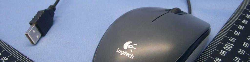
4 1 CERTIFICATION PRODUCT: Corded Mouse BRAND NAME: Logitech MODEL NO.: M-U0026 TESTED: June 22 to 23, 2010 TEST SAMPLE: ENGINEERING SAMPLE APPLICANT: LOGITECH FAR EAST LTD. STANDARDS: EN 55022:2006+A1:2007, Class B EN 55024:1998+A1:2001 AS/NZS CISPR 22:2006, Class B +A2:2003 EN :2006, Class A EN :2008 IEC :2008 ED.2.0 IEC :2008 ED.3.1 IEC :2004 ED.2.0 IEC :2005 ED.2.0 IEC :2008 ED.3.0 IEC :2009 ED.2.0 IEC :2004 ED.2.0 The above equipment (Model: M-U0026) has been tested by Bureau Veritas Consumer Products Services (H.K.) Ltd., Taoyuan Branch, and found compliance with the requirement of the above standards. The test record, data evaluation & Equipment Under Test (EUT) configurations represented herein are true and accurate accounts of the measurements of the sample s EMC characteristics under the conditions specified in this report. PREPARED BY :, DATE: June 24, 2010 ( Carol Liao, Specialist ) TECHNICAL ACCEPTANCE :, DATE: June 24, 2010 ( Ray Yeh, Deputy Manager ) APPROVED BY :, DATE: June 24, 2010 ( May Chen, Deputy Manager ) Report No.: CE990621E07 4 Report Format Version 3.0.3
5 2 SUMMARY OF TEST RESULTS The EUT has been tested according to the following specifications: EMISSION Standard Test Type Result Remarks Conducted Test PASS Meets Class B Limit Minimum passing margin is db at MHz EN 55022:2006 +A1:2007, Class B EN :2006, Class A EN :2008 IEC :2008 ED.2.0 IEC :2008 ED.3.1 Telecom port conducted emission test Radiated Test Harmonic current emissions Voltage fluctuations & flicker NA PASS PASS PASS Not Applicable Meets Class B Limit Minimum passing margin is db at MHz The power consumption of EUT is less than 75W and no limits apply Meets the requirements IMMUNITY (EN 55024:1998+A1:2001+A2:2003) Standard Test Type Result Remarks Electrostatic discharge Meets the requirements of PASS immunity test Performance Criterion A Radiated, radio-frequency, Meets the requirements of PASS electromagnetic field Performance Criterion A immunity test IEC :2004 ED.2.0 IEC :2005 ED.2.0 IEC :2008 ED.3.0 IEC :2009 ED.2.0 IEC :2004 ED.2.0 Electrical fast transient / burst immunity test. Surge immunity test Immunity to conducted disturbances, induced by radio-frequency fields Power frequency magnetic field immunity test. Voltage dips, short interruptions and voltage variations immunity tests PASS PASS PASS PASS PASS Meets the requirements of Performance Criterion B Meets the requirements of Performance Criterion A Meets the requirements of Performance Criterion A Meets the requirements of Performance Criterion A Meets the requirements of Voltage Dips: i) >95% reduction period, Performance Criterion A ii) 30% reduction - 25 period, Performance Criterion A Voltage Interruptions: i) >95% reduction -250 period, Performance Criterion C Report No.: CE990621E07 5 Report Format Version 3.0.3
6 2.1 MEASUREMENT UNCERTAINTY Where relevant, the following measurement uncertainty levels have been estimated for tests performed on the EUT as specified in CISPR : This uncertainty represents an expanded uncertainty expressed at approximately the 95% confidence level using a coverage factor of k=2. Measurement Conducted emissions Radiated emissions (30MHz-1GHz) Value 2.45 db 3.21 db Report No.: CE990621E07 6 Report Format Version 3.0.3
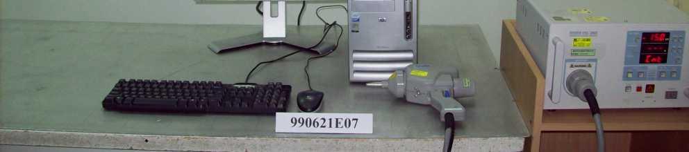
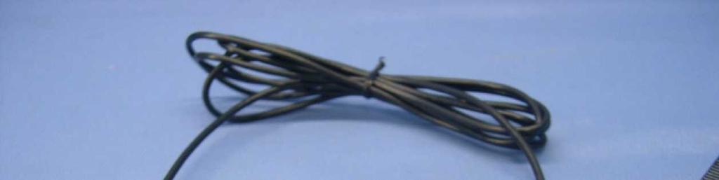
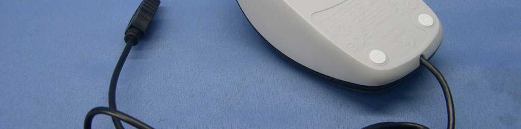
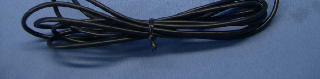
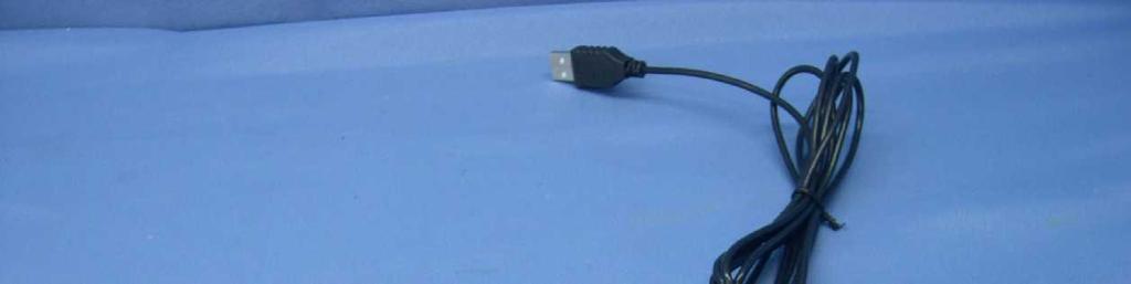
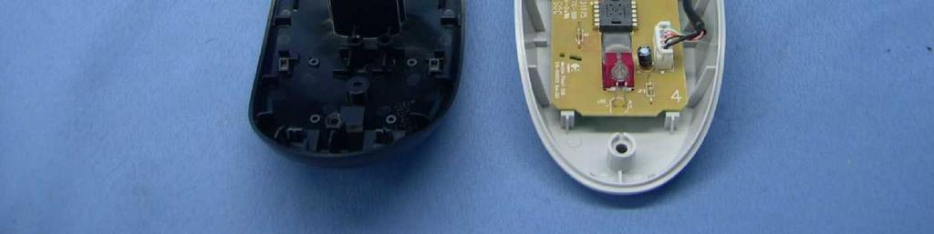
7 3 GENERAL INFORMATION 3.1 GENERAL DESCRIPTION OF EUT PRODUCT Corded Mouse MODEL NO. M-U0026 POWER SUPPLY DC 5V from host equipment POWER CORD NA DATA CABLE SUPPLIED USB cable (shielded, 1.85 m) INTERFACE USB interface NOTE: 1. For a more detailed features description, please refer to the manufacturer's specifications or the User's Manual. 3.2 GENERAL DESCRIPTION OF TEST MODE The EUT was tested under following test mode: Test Mode Mode 1 Description Normal mode Report No.: CE990621E07 7 Report Format Version 3.0.3
8 3.3 GENERAL DESCRIPTION OF APPLIED STANDARDS The EUT is a kind of IT equipment and, according to the specifications of the manufacturers, must comply with the requirements of the following standards: EN 55022:2006+A;2007, Class B AS/NZS CISPR 22:2006, Class B EN :2006, Class A EN :2008 EN 55024:1998+A1:2001+A2:2003 IEC :2008 ED.2.0 IEC :2008 ED.3.1 IEC :2004 ED.2.0 IEC :2005 ED.2.0 IEC :2008 ED.3.0 IEC :2009 ED.2.0 IEC :2004 ED.2.0 Note: The above IEC basic standards are applied with latest version if customer has no special requirement All tests have been performed and recorded as per the above standards. Report No.: CE990621E07 8 Report Format Version 3.0.3
9 3.4 DESCRIPTION OF SUPPORT UNITS The EUT has been tested as an independent unit together with other necessary accessories or support units. The following support units or accessories were used to form a representative test configuration during the tests. Conducted test No. Product Brand Model No. Serial No. FCC ID 1 PERSONAL COMPUTER DELL DCSM G84QL1S FCC DoC 2 MONITOR DELL E228WFPc CN-OX765G P-0BTM FCC DoC 3 PRINTER EPSON LQ-300+ DCGY FCC DoC 4 MODEM ACEEX IFAXDM KEYBOARD DELL SK-8115 MY-0DJ B-0476 FCC DoC Radiated test No. Product Brand Model No. Serial No. FCC ID 1 PERSONAL COMPUTER DELL DCSCMF 9KKB32S FCC DoC 2 MONITOR DELL E2210Hc CN-OG337R S-OQDS FCC DoC 3 PRINTER CANON K10202 FASF84644 FCC DoC 4 MODEM ACEEX IFAXDM KEYBOARD DELL SK-8115 MY-0DJ B-0476 FCC DoC Harmonics Current / Voltage Fluctuation and Flicker / Immunity test No. Product Brand Model No. Serial No. FCC ID 1 PERSONAL COMPUTER HP DX7300MT SGH7500R7H FCC DoC 2 MONITOR DELL 2007FPb CN-0DC V-12WS FCC DoC 3 KEYBOARD DELL SK-8115 MY-0J V-0350 FCC DoC Conducted / Radiated test No. Signal cable description 1 NA m braid shielded wire, terminated with VGA connector via metallic frame, with two cores m braid shielded wire, terminated with DB25 and centronics connector via metallic frame, w/o core m braid shielded wire, terminated with DB25 and DB9 connector via metallic frame, w/o core m foil shielded wire, terminal by frame, USB Connector, w/o Core. Harmonics Current / Voltage Fluctuation and Flicker / Immunity test No. Signal cable description 1 NA m braid shielded wire, terminated with VGA connector via metallic frame, with two cores m foil shielded wire, terminal by frame, USB Connector, w/o Core. NOTE: All power cords of the above support units are non shielded (1.8m). Report No.: CE990621E07 9 Report Format Version 3.0.3
10 3.5 CONFIGURATION OF SYSTEM UNDER TEST For Conducted and Radiated test: 3. PRINTER 1. PC 2. MONITOR 4. MODEM USB cable (1.85m) 5. KEYBOARD EUT TEST TABLE For Harmonics Current / Voltage Fluctuation and Flicker / Immunity test: 1. PC 2. MONITOR USB cable (1.85m) 3. KEYBOARD EUT TEST TABLE Report No.: CE990621E07 10 Report Format Version 3.0.3
11 4 EMISSION TEST 4.1 CONDUCTED EMISSION MEASUREMENT LIMITS OF CONDUCTED EMISSION MEASUREMENT TEST STANDARD: EN FREQUENCY (MHz) Class A (dbuv) Class B (dbuv) Quasi-peak Average Quasi-peak Average NOTE: (1) The lower limit shall apply at the transition frequencies. (2) The limit decreases in line with the logarithm of the frequency in the range of 0.15 to 0.50 MHz. (3) All emanations from a class A/B digital device or system, including any network of conductors and apparatus connected thereto, shall not exceed the level of field strengths specified above TEST INSTRUMENTS DESCRIPTION & MANUFACTURER ROHDE & SCHWARZ Test Receiver Line-Impedance Stabilization Network (for EUT) Line-Impedance Stabilization Network (for Peripheral) MODEL NO. SERIAL NO. CALIBRATED DATE CALIBRATED UNTIL ESCS Mar. 01, 2010 Feb. 28, 2011 NSLK Sep. 23, 2009 Sep. 22, 2010 ENV June 11, 2010 June 10, 2011 RF Cable (JYEBAO) 5DFB COACAB-001 Dec. 14, 2009 Dec. 13, ohms Terminator 50 3 Oct. 28, 2009 Oct. 27, 2010 Software BV ADT_Cond_V7.3.7 NA NA NA Note: 1. The calibration interval of the above test instruments is 12 months and the calibrations are traceable to NML/ROC and NIST/USA. 2. The test was performed in Shielded Room No. A. 3 The VCCI Con A Registration No. is C-817. Report No.: CE990621E07 11 Report Format Version 3.0.3
12 4.1.3 TEST PROCEDURE a. The EUT was placed 0.4 meters from the conducting wall of the shielded room with EUT being connected to the power mains through a line impedance stabilization network (LISN). Other support units were connected to the power mains through another LISN. The two LISNs provide 50 Ohm/ 50uH of coupling impedance for the measuring instrument. b. Both lines of the power mains connected to the EUT were checked for maximum conducted interference. c. The frequency range from 150 khz to 30 MHz was searched. Emission levels over 10dB under the prescribed limits could not be reported DEVIATION FROM TEST STANDARD No deviation TEST SETUP Vertical Reference Ground Plane Test Receiver 40cm EUT LISN 80cm Note: 1.Support units were connected to second LISN. 2.Both of LISNs (AMN) are 80 cm from EUT and at least 80 from other units and other metal planes Horizontal Reference Ground Plane For the actual test configuration, please refer to the related item Photographs of the Test Configuration. Report No.: CE990621E07 12 Report Format Version 3.0.3
13 4.1.6 EUT OPERATING CONDITIONS 1. Turn on the power of all equipment. 2. Set the EUT under typical use condition. 3. PC runs test program mspaint.exe. 4. PC sends "H" messages to monitor, and displays H messages on its screen. 5. PC sends "H" messages to modem. 6. PC sends "H" messages to printer, and the printer prints them on paper. 7. Repeat steps 2-6. Report No.: CE990621E07 13 Report Format Version 3.0.3
14 4.1.7 TEST RESULTS TEST MODE Mode 1 PHASE Line (L) INPUT POWER (SYSTEM) 230Vac, 50 Hz 6dB BANDWIDTH 9 khz ENVIRONMENTAL CONDITIONS 25 deg. C, 60 % RH, 1014 hpa TESTED BY Max Tseng Freq. Corr. Reading Value Emission Level Limit Margin No Factor [db (uv)] [db (uv)] [db (uv)] (db) [MHz] (db) Q.P. AV. Q.P. AV. Q.P. AV. Q.P. AV REMARKS: 1. Q.P. and AV. are abbreviations of quasi-peak and average individually. 2. "-": The Quasi-peak reading value also meets average limit and measurement with the average detector is unnecessary. 3. The emission levels of other frequencies were very low against the limit. 4. Margin value = Emission level - Limit value 5. Correction factor = Insertion loss + Cable loss 6. Emission Level = Correction Factor + Reading Value. Report No.: CE990621E07 14 Report Format Version 3.0.3
] [db (uv)] [db (uv)] (db) [MHz] (db) Q.P. AV. Q.P. AV. Q.P. AV. Q.P. AV. 1 0.166 0.05 36.29-36.34-65.18 55.18-28.84-2 0.205 0.05 48.04-48.")
15 TEST MODE Mode 1 PHASE Neutral (N) INPUT POWER (SYSTEM) ENVIRONMENTAL CONDITIONS 230Vac, 50 Hz 6dB BANDWIDTH 9 khz 25 deg. C, 60 % RH, 1014 hpa TESTED BY Max Tseng Freq. Corr. Reading Value Emission Level Limit Margin No Factor [db (uv)] [db (uv)] [db (uv)] (db) [MHz] (db) Q.P. AV. Q.P. AV. Q.P. AV. Q.P. AV REMARKS: 1. Q.P. and AV. are abbreviations of quasi-peak and average individually. 2. "-": The Quasi-peak reading value also meets average limit and measurement with the average detector is unnecessary. 3. The emission levels of other frequencies were very low against the limit. 4. Margin value = Emission level - Limit value 5. Correction factor = Insertion loss + Cable loss 6. Emission Level = Correction Factor + Reading Value. Report No.: CE990621E07 15 Report Format Version 3.0.3
16 4.2 RADIATED EMISSION MEASUREMENT LIMITS OF RADIATED EMISSION MEASUREMENT TEST STANDARD: EN FOR FREQUENCY BELOW 1000 MHz FREQUENCY Class A (at 10m) Class B (at 10m) (MHz) dbuv/m dbuv/m FOR FREQUENCY ABOVE 1000 MHz FREQUENCY (GHz) Class A (dbuv/m) (at 3m) Class B (dbuv/m) (at 3m) PEAK AVERAGE PEAK AVERAGE 1 to to NOTE: (1) The lower limit shall apply at the transition frequencies. (2) Emission level (dbuv/m) = 20 log Emission level (uv/m). (3) All emanation from a class A/B digital device or system, including any network of conductors and apparatus connected thereto, shall not exceed the level of field strengths specified above. FREQUENCY RANGE OF RADIATED MEASUREMENT (For unintentional radiators) Highest frequency generated or Upper frequency of measurement used in the device or on which the device operates or tunes (MHz) Range (MHz) Below Above 1000 Up to 5 times of the highest frequency or 6 GHz, whichever is less Report No.: CE990621E07 16 Report Format Version 3.0.3
17 4.2.2 TEST INSTRUMENTS DESCRIPTION & CALIBRATED CALIBRATED MODEL NO. SERIAL NO. MANUFACTURER DATE UNTIL Agilent E4443A MY Aug. 03, 2009 Aug. 02, 2010 Spectrum Analyzer E4443A MY Oct. 31, 2009 Oct. 30, 2010 Agilent N9039A MY Nov. 20, 2009 Nov. 19, 2010 Pre-Selector N9039A MY July 25, 2009 July 24, 2010 Agilent Signal Generator N5181A MY July 20, 2009 July 19, 2010 Mini-Circuits ZFL-1000VH2B AMP-ZFL-01 Nov. 18, 2009 Nov. 17, 2010 Pre-Amplifier ZFL-1000VH2B AMP-ZFL-02 Nov. 18, 2009 Nov. 17, 2010 Mini-Circuits Pre_Amplifier ZVA-183-S+ AMP-ZVA-01 Nov. 18, 2009 Nov. 17, 2010 (1~18GHz) SPACEK LABS (15~40GHz) SLKKa K16 NA NA SCHWARZBECK VULB Sep. 30, 2009 Sep. 29, 2010 Trilog Broadband Antenna VULB Sep. 30, 2009 Sep. 29, 2010 SCHWARZBECK BBHA Sep. 30, 2009 Sep. 29, 2010 Horn Antenna BBHA D-783 Sep. 30, 2009 Sep. 29, 2010 RF CABLE NA RF RF RF Dec. 24, 2009 Dec. 23, 2010 ADT_Radiated_ Software NA NA NA V CT Antenna Tower & NA NA NA NA Turn Table Note: 1. The calibration interval of the above test instruments is 12 months and the calibrations are traceable to NML/ROC and NIST/USA. 2. The test was performed in 10m Chamber No. F. 3. The FCC Site Registration No. is The VCCI Site Registration No. is R-3252 & G The CANADA Site Registration No. is IC 7450H-1. Report No.: CE990621E07 17 Report Format Version 3.0.3
18 4.2.3 TEST PROCEDURE a. The EUT was placed on the top of a rotating table 0.8 meters above the ground at a 10 meters Semi-anechoic chamber room. The table was rotated 360 degrees to determine the position of the highest radiation. b. The EUT was set 10 meters away from the interference-receiving antenna, which was mounted on the top of a variable-height antenna tower. c. The antenna is a broadband antenna, and its height is varied from one meter to four meters above the ground to determine the maximum value of the field strength. Both horizontal and vertical polarization of the antenna are set to make the measurement. d. For each suspected emission, the EUT was arranged to its worst case and then the antenna was tuned to heights from 1 meter to 4 meters and the turn table was turned from 0 degrees to 360 degrees to find the maximum reading. e. The test-receiver system was set to quasi-peak detect function and specified bandwidth with maximum hold mode when the test frequency is below 1 GHz. NOTE: The resolution bandwidth of test receiver/spectrum analyzer is 120kHz for Quasi-peak detection (QP) at frequency below 1GHz DEVIATION FROM TEST STANDARD No deviation Report No.: CE990621E07 18 Report Format Version 3.0.3

19 4.2.5 TEST SETUP For the actual test configuration, please refer to the related item Photographs of the Test Configuration EUT OPERATING CONDITIONS Same as Report No.: CE990621E07 19 Report Format Version 3.0.3
20 4.2.7 TEST RESULTS TEST MODE Mode1 INPUT POWER (SYSTEM) 230Vac, 50Hz FREQUENCY RANGE MHz DETECTOR FUNCTION & BANDWIDTH Quasi-Peak, 120kHz ENVIRONMENTAL CONDITIONS 27 deg. C, 75 % RH, 1014 hpa TESTED BY Kyle Huang No. ANTENNA POLARITY & TEST DISTANCE: HORIZONTAL AT 10 M Freq. (MHz) Emission Level (dbuv/m) Limit (dbuv/m) Margin (db) Antenna Height (m) Table Angle (Degree) Raw Value (dbuv) Correction Factor (db/m) QP H QP H QP H QP H QP H QP H REMARKS: 1. Emission level(dbuv/m)=raw Value(dBuV) + Correction Factor(dB/m) 2. Correction Factor(dB/m) = Antenna Factor (db/m) + Cable Factor (db) 3. The other emission levels were very low against the limit. 4. Margin value = Emission level Limit value. Report No.: CE990621E07 20 Report Format Version 3.0.3

21 TEST MODE Mode 1 FREQUENCY RANGE MHz INPUT POWER (SYSTEM) DETECTOR FUNCTION & BANDWIDTH 230Vac, 50Hz Quasi-Peak, 120kHz ENVIRONMENTAL CONDITIONS 27 deg. C, 75 % RH, 1014 hpa TESTED BY Kyle Huang No. ANTENNA POLARITY & TEST DISTANCE: VERTICAL AT 10 M Freq. (MHz) Emission Level (dbuv/m) Limit (dbuv/m) Margin (db) Antenna Height (m) Table Angle (Degree) Raw Value (dbuv) Correction Factor (db/m) QP V QP V QP V QP V QP V QP V REMARKS: 1. Emission level(dbuv/m)=raw Value(dBuV) + Correction Factor(dB/m) 2. Correction Factor(dB/m) = Antenna Factor (db/m) + Cable Factor (db) 3. The other emission levels were very low against the limit. 4. Margin value = Emission level Limit value. Report No.: CE990621E07 21 Report Format Version 3.0.3
22 4.3 HARMONICS CURRENT MEASUREMENT LIMITS OF HARMONICS CURRENT MEASUREMENT TEST STANDARD: EN Limits for Class A equipment Harmonics Max. permissible Harmonics Order harmonics current Order n A n Limits for Class D equipment Max. permissible Max. permissible harmonics current per harmonics current watt ma/w A Odd harmonics Odd Harmonics only <=n<= x15/n 15<=n<= /n 0.15x15/n Even harmonics <=n<= x8/n NOTE: 1. The classifications of equipment are defined in Section 5 of EN The above limits for all equipment except for lighting equipment are for all applications having an active input power > 75 W. No limits apply for equipment with an active input power up to and including 75 W TEST INSTRUMENTS DESCRIPTION & MANUFACTURER EMC PARTNER EMC Emission Tester MODEL NO. SERIAL NO. CALIBRATED DATE CALIBRATED UNTIL HAR1000-1P 086 Aug. 11, 2009 Aug. 10, 2010 EMC Partner(Software) HARCS_V4.16 NA NA NA NOTE: 1. The calibration interval of the above test instruments is 12 months and the calibrations are traceable to NML/ROC and NIST/USA. 2. The test was performed in EMS room. Report No.: CE990621E07 22 Report Format Version 3.0.3
23 4.3.3 TEST PROCEDURE a. The EUT was placed on the top of a wooden table 0.8 meters above the ground and operated to produce the maximum harmonic components under normal operating conditions for each successive harmonic component in turn. b. The classification of EUT is according to section 5 of EN The EUT is classified as follows: Class A: Balanced three-phase equipment, Household appliances excluding equipment as Class D, Tools excluding portable tools, Dimmers for incandescent lamps, audio equipment, equipment not specified in one of the three other classes. Class B: Portable tools.; Arc welding equipment which is not professional equipment Class C: Lighting equipment. Class D: Equipment having a specified power less than or equal to 600 W of the following types: Personal computers and personal computer monitors and television receivers. c. The correspondent test program of test instrument to measure the current harmonics emanated from EUT is chosen. The measure time shall be not less than the time necessary for the EUT to be exercised TEST SETUP EUT For the actual test configuration, please refer to the related item Photographs of the Test Configuration EUT OPERATING CONDITIONS 1. Turn on the power of all equipment. 2. Set the EUT for typical use condition. 3. PC runs test program mspaint.exe. 4. Repeat steps 2-3. Report No.: CE990621E07 23 Report Format Version 3.0.3
24 4.3.6 TEST RESULTS FUNDAMENTAL VOLTAGE/AMPERE Vrms / Arms POWER FREQUENCY 50 Hz POWER CONSUMPTION W POWER FACTOR ENVIRONMENTAL CONDITIONS 25 deg. C, 63 % RH, 1014 hpa TESTED BY Jason Huang NOTE: Limits are not specified for equipment with a rated power of 75W or less (other than lighting equipment). Report No.: CE990621E07 24 Report Format Version 3.0.3
25 4.4 VOLTAGE FLUCTUATION AND FLICKER MEASUREMENT LIMITS OF VOLTAGE FLUCTUATION AND FLICKER MEASUREMENT TEST STANDARD: EN TEST ITEM LIMIT NOTE P st 1.0 P st means short-term flicker indicator. P lt 0.65 P lt means long-term flicker indicator. 500 T T dt (ms) dt means maximum time that dt exceeds 3.3 %. 4% d d max (%) max means maximum relative voltage change. 3.3% dc means relative steady-state voltage dc (%) change TEST INSTRUMENTS DESCRIPTION & MANUFACTURER EMC PARTNER EMC Emission Tester MODEL NO. SERIAL NO. CALIBRATED DATE CALIBRATED UNTIL HAR1000-1P 086 Aug. 11, 2009 Aug. 10, 2010 EMC Partner(Software) HARCS_V4.16 NA NA NA NOTE: 1. The calibration interval of the above test instruments is 12 months and the calibrations are traceable to NML/ROC and NIST/USA. 2. The test was performed in EMS room TEST PROCEDURE a. The EUT was placed on the top of a wooden table 0.8 meters above the ground and operated to produce the most unfavorable sequence of voltage changes under normal operating conditions. b. During the flick measurement, the measure time shall include that part of whole operation cycle in which the EUT produce the most unfavorable sequence of voltage changes. The observation period for short-term flicker indicator is 10 minutes and the observation period for long-term flicker indicator is 2 hours. Report No.: CE990621E07 25 Report Format Version 3.0.3
26 4.4.4 TEST SETUP EUT For the actual test configuration, please refer to the related item Photographs of the Test Configuration EUT OPERATING CONDITIONS Same as Report No.: CE990621E07 26 Report Format Version 3.0.3
27 4.4.6 TEST RESULTS FUNDAMENTAL VOLTAGE/AMPERE OBSERVATION PERIOD (TP) ENVIRONMENTAL CONDITIONS Vrms / Arms POWER FREQUENCY 50 Hz 10 min. POWER FACTOR deg. C, 63 % RH, 1014 hpa TESTED BY Jason Huang TEST PARAMETER MEASUREMENT VALUE LIMIT REMARKS P st Pass P lt Pass T dt (ms) Pass d max (%) % Pass dc (%) % Pass NOTE: (1) P st means short-term flicker indicator. (2) P lt means long-term flicker indicator. (3) T dt means maximum time that dt exceeds 3.3 %. (4) d max means maximum relative voltage change. (5) dc means relative steady-state voltage change. Report No.: CE990621E07 27 Report Format Version 3.0.3
28 5 IMMUNITY TEST 5.1 GENERAL DESCRIPTION Product Standard: EN 55024:1998+A1:2001+A2:2003 Basic Standard, Specification, and Performance Criteria: IEC IEC IEC IEC IEC IEC Electrostatic Discharge - ESD: 8kV air discharge, 4kV Contact discharge, Performance Criterion B Radio-Frequency Electromagnetic Field Susceptibility Test - RS: MHz, 3V/m, 80% AM (1kHz), Performance Criterion A Electrical Fast Transient/Burst - EFT, Power line: 1kV, Signal line: 0.5kV, Performance Criterion B Surge Immunity Test: 1.2/50 us Open Circuit Voltage, 8 /20 us Short Circuit Current AC Power Line: line to line 1 kv, line to earth 2kV DC Power Line: line to earth 0.5kV Signal line: 1kV Performance Criterion B Conducted Radio Frequency Disturbances Test - CS: MHz, 3V, 80% AM, 1kHz, Performance Criterion A Power Frequency Magnetic Field Test, 50 Hz, 1A/m, Performance Criterion A IEC Voltage Dips: i) >95% reduction -0.5 period, Performance Criteria B ii) 30% reduction - 25 period, Performance Criterion C Voltage Interruptions: i) >95% reduction period, Performance Criterion C Report No.: CE990621E07 28 Report Format Version 3.0.3
29 5.2 GENERAL PERFORMANCE CRITERIA DESCRIPTION According to Clause 7.1 of EN standard, the following describes the general performance criteria. CRITERION A CRITERION B CRITERION C The equipment shall continue to operate as intended without operator intervention. No degradation of performance or loss of function is allowed below a performance level specified by the manufacturer when the equipment is used as intended. The performance level may be replaced by a permissible loss of performance. If the minimum performance level or the permissible performance loss is not specified by the manufacturer, then either of these may be derived from the product description and documentation, and by what the user may reasonably expect from the equipment if used as intended. After the test, the equipment shall continue to operate as intended without operator intervention. No degradation of performance or loss of function is allowed, after the application of the phenomenon below a performance level specified by the manufacturer, when the equipment is used as intended. The performance level may be replaced by a permissible loss of performance. During the test, degradation of performance is allowed. However, no change of operating state if stored data is allowed to persist after the test. If the minimum performance level (or the permissible performance loss) is not specified by the manufacturer, then either of these may be derived from the product description and documentation, and by what the user may reasonably expect from the equipment if used as intended. Loss of function is allowed, provided the function is self-recoverable, or can be restored by the operation of the controls by the user in accordance with the manufacturer s instructions. Functions, and/or information stored in non-volatile memory, or protected by a battery backup, shall not be lost. 5.3 EUT OPERATING CONDITION Same as Report No.: CE990621E07 29 Report Format Version 3.0.3
30 5.4 ELECTROSTATIC DISCHARGE IMMUNITY TEST (ESD) TEST SPECIFICATION Basic Standard: IEC Discharge Impedance: 330 ohm / 150 pf Discharge Voltage: Air Discharge 2, 4, 8, 10, 12, 15 kv (Direct) Contact Discharge 2, 4, 6, 8 kv (Direct/Indirect) Polarity: Positive / Negative Number of Discharge: Air Discharge: min. 20 times at each test point Contact Discharge: min. 50 times at each test point Discharge Mode: Single Discharge Discharge Period: 1-second minimum TEST INSTRUMENTS DESCRIPTION & SERIAL CALIBRATED CALIBRATED MODEL NO. MANUFACTURER NO. DATE UNTIL NoiseKen, ESD Simulator ESS-100L(A) 0189C01491 July 17, 2009 July 16, 2010 Key Tek, ESD Simulator MZ-15/EC June 11, 2010 June 10, 2011 Key Tek, ESD Simulator MZ-15/EC Jan. 06, 2010 Jan. 05, 2011 NoiseKen, ESD Simulator ESS-2002 ESS /244 May 07, 2010 May 08, 2011 NOTE: 1. The calibration interval of the above test instruments is 12 months and the calibrations are traceable to NML/ROC and NIST/USA. 2. The test was performed in ESD room A TEST PROCEDURE The discharges shall be applied in two ways: a. Contact discharges to the conductive surfaces and coupling planes: The EUT shall be exposed to at least 200 discharges, 100 each at negative and positive polarity, at a minimum of four test points. One of the test points shall be subjected to at least 50 indirect discharges to the center of the front edge of the horizontal coupling plane. The remaining three test points shall each receive at least 50 direct contact discharges. If no direct contact test points are available, then at least 200 indirect discharges shall be applied in the indirect mode. Test shall be performed at a maximum repetition rate of one discharge per second. b. Air discharges at slots and apertures and insulating surfaces: On those parts of the EUT where it is not possible to perform contact discharge testing, the equipment should be investigated to identify user accessible points where breakdown may occur. Such points are tested using the air discharge method. This investigation should be restricted to those area normally handled by the user. A minimum of 10 single air discharges shall be applied to the selected test point for each such area. Report No.: CE990621E07 30 Report Format Version 3.0.3
31 The basic test procedure was in accordance with IEC : a. Electrostatic discharges were applied only to those points and surfaces of the EUT that are accessible to users during normal operation. b. The test was performed with at least ten single discharges on the pre-selected points in the most sensitive polarity. c. The time interval between two successive single discharges was at least 1 second. d. The ESD generator was held perpendicularly to the surface to which the discharge was applied and the return cable was at least 0.2 meters from the EUT. e. Contact discharges were applied to the non-insulating coating, with the pointed tip of the generator penetrating the coating and contacting the conducting substrate. f. Air discharges were applied with the round discharge tip of the discharge electrode approaching the EUT as fast as possible (without causing mechanical damage) to touch the EUT. After each discharge, the ESD generator was removed from the EUT and re-triggered for a new single discharge. The test was repeated until all discharges were complete. g. At least ten single discharges (in the most sensitive polarity) were applied to the Horizontal Coupling Plane at points on each side of the EUT. The ESD generator was positioned at a distance of 0.1 meters from the EUT with the discharge electrode touching the HCP. h. At least ten single discharges (in the most sensitive polarity) were applied to the center of one vertical edge of the Vertical Coupling Plane in sufficiently different positions that the four faces of the EUT were completely illuminated. The VCP (dimensions 0.5m x 0.5m) was placed vertically to and 0.1 meters from the EUT DEVIATION FROM TEST STANDARD As per client requests, the following discharge levels were also applied: Contact Discharge 6, 8kV for indirect contact discharge Air Discharge 10, 12, 15 kv for direct air discharge. Report No.: CE990621E07 31 Report Format Version 3.0.3
32 5.4.5 TEST SETUP 1m 0.1m Vertical coupling plane Nearest Wall PS ESD Generator Horizontal coupling plane EUT 0.5mm Isolation Support 80cm 470k X4 Reference Ground Plane For the actual test configuration, please refer to the related item Photographs of the Test Configuration. NOTE: TABLE-TOP EQUIPMENT The configuration consisted of a wooden table 0.8 meters high standing on the Ground Reference Plane. The GRP consisted of a sheet of aluminum at least 0.25mm thick, and 2.5 meters square connected to the protective grounding system. A Horizontal Coupling Plane (1.6m x 0.8m) was placed on the table and attached to the GRP by means of a cable with 940kΩ total impedance. The equipment under test, was installed in a representative system as described in section 7 of IEC , and its cables were placed on the HCP and isolated by an insulating support of 0.5mm thickness. A distance of 1-meter minimum was provided between the EUT and the walls of the laboratory and any other metallic structure. FLOOR-STANDING EQUIPMENT The equipment under test was installed in a representative system as described in section 7 of IEC , and its cables were isolated from the Ground Reference Plane by an insulating support of 0.1-meter thickness. The GRP consisted of a sheet of aluminum that is at least 0.25mm thick, and 2.5 meters square connected to the protective grounding system and extended at least 0.5 meters from the EUT on all sides. Report No.: CE990621E07 32 Report Format Version 3.0.3
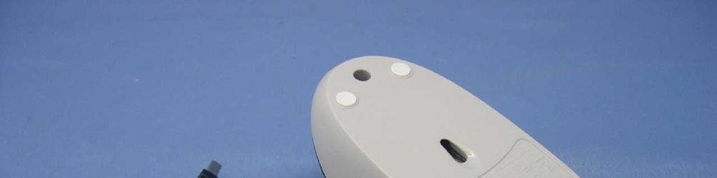
33 5.4.6 TEST RESULTS TEST MODE Mode 1 ENVIRONMENTAL CONDITIONS 26 deg. C, 41 % RH, 1014 hpa INPUT POWER (SYSTEM) TESTED BY 230Vac, 50 Hz Jason Huang TEST RESULTS OF DIRECT APPLICATION Discharge Polarity Contact Performance Test Point Air Discharge Level (kv) (+/-) Discharge Criterion 2, 4, 8, 10, +/- 1 ~ 6 NA Note (1) A 12, 15 Note: No conductive surfaces found, therefore no contact discharge was executed. Description of test point: Please refer to following page for representative mark only. Discharge Level (kv) TEST RESULTS OF INDIRECT APPLICATION Horizontal Vertical Polarity Test Point Coupling Coupling (+/-) Plane Plane Performance Criterion 2, 4, 6, 8 +/- 1 ~ 4 Note (1) Note (1) A Description of test point: 1. Front side 2. Right side 3. Left side 4. Rear side NOTE: (1) There was no change compared with initial operation during the test. (2) The EUT function delayed during the test but it could be self-recoverable after the test. The air discharge level which over 8kV and contact discharge which over 4kV is not required by EN for IT equipment. It is according to the requirement of the manufacturer; the data of test result is only for manufacture s reference. Report No.: CE990621E07 33 Report Format Version 3.0.3


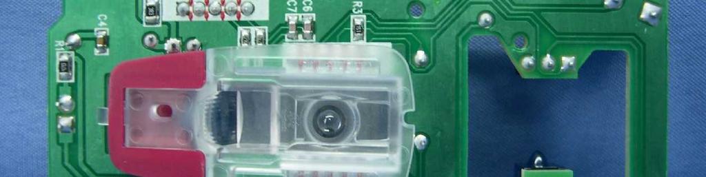
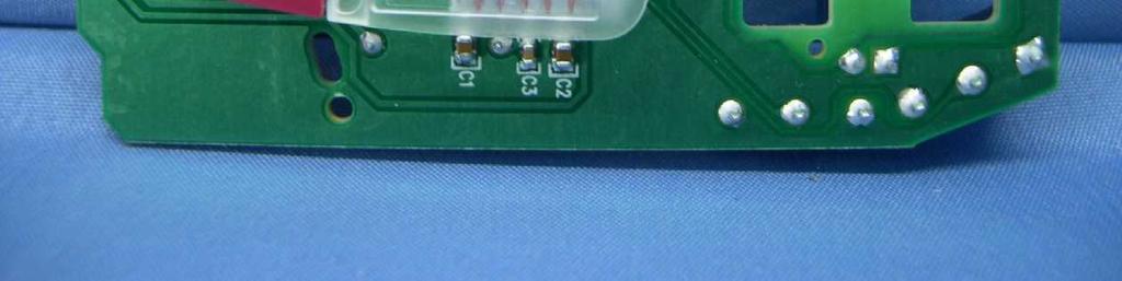
34 DESCRIPTION OF TEST POINT Report No.: CE990621E07 34 Report Format Version 3.0.3


35 5 6 Report No.: CE990621E07 35 Report Format Version 3.0.3
36 5.5 RADIATED, RADIO-FREQUENCY, ELECTROMAGNETIC FIELD IMMUNITY TEST (RS) TEST SPECIFICATION Basic Standard: IEC Frequency Range: 80 MHz MHz Field Strength: 3 V/m Modulation: 1kHz Sine Wave, 80%, AM Modulation Frequency Step: 1 % of fundamental Polarity of Horizontal and Vertical Antenna: Antenna Height: 1.5m Dwell Time: 3 seconds TEST INSTRUMENTS DESCRIPTION & MANUFACTURER MODEL NO. SERIAL NO. CALIBRATED DATE CALIBRATED UNTIL AR Power Amplifier 150W1000M NA NA AR Power Amplifier 60S1G3M NA NA AR LOG ANTENNA AT5080ANT NA NA BOONTON RF Voltage Meter 4232A Dec. 19, 2009 Dec. 18, 2010 R&S Signal Generator SML Dec. 28, 2009 Dec. 27, 2010 Electric Field Probe FP Dec. 04, 2009 Dec. 03, 2010 ADT RS Test Workbench(Software) ADT_RS_V7.5 NA NA NA NOTE: 1. The calibration interval of the above test instruments is 12 months and the calibrations are traceable to NML/ROC and NIST/USA. 2. The test was performed in Chamber Room No. B. 3. The transmit antenna was located at a distance of 2.0 meters from the EUT. Report No.: CE990621E07 36 Report Format Version 3.0.3
37 5.5.3 TEST PROCEDURE The test procedure was in accordance with IEC a. The testing was performed in a fully-anechoic chamber. b. The frequency range is swept from 80 MHz to 1000 MHz with the signal 80% amplitude modulated with a 1kHz sine wave. c. The dwell time at each frequency shall not be less than the time necessary for the EUT to be exercised and to respond, but shall in no case be less than 0,5s. d. The field strength level was 3V/m. e. The test was performed with the EUT exposed to both vertically and horizontally polarized fields on each of the four sides TEST SETUP 3m measurement distance in a Full Anechoic Chamber EUT RF Amplifier RF Generator and control system Monitoring system For the actual test configuration, please refer to the related item Photographs of the Test Configuration. NOTE: TABLETOP EQUIPMENT The EUT installed in a representative system as described in section 7 of IEC was placed on a non-conductive table 0.8 meters in height. The system under test was connected to the power and signal wire according to relevant installation instructions. FLOOR STANDING EQUIPMENT The EUT installed in a representative system as described in section 7 of IEC was placed on a non-conductive wood support 0.1 meters in height. The system under test was connected to the power and signal wire according to relevant installation instructions. Report No.: CE990621E07 37 Report Format Version 3.0.3
38 5.5.5 TEST RESULTS TEST MODE Mode 1 INPUT POWER (SYSTEM) 230Vac, 50 Hz ENVIRONMENTAL CONDITIONS 23 deg. C, 57 % RH, 1014 hpa TESTED BY Mike Hsieh Frequency (MHz) Result Polarity Azimuth Field Strength (V/m) PASS V&H PASS V&H PASS V&H PASS V&H Observation Note Performance Criterion A NOTE: There was no change compared with the initial operation during the test. Report No.: CE990621E07 38 Report Format Version 3.0.3
39 5.6 ELECTRICAL FAST TRANSIENT/BURST IMMUNITY TEST (EFT) TEST SPECIFICATION Basic Standard: IEC Test Voltage: Power Line 1kV / 2kVSignal/Control Line 0.5kV / 2kV Polarity: Positive & Negative Impulse 5 khz Frequency: Impulse 5/50 ns Wave shape : Burst Duration: 15 ms Burst Period: 300 ms Test Duration: 1 min TEST INSTRUMENTS DESCRIPTION & CALIBRATED CALIBRATED MODEL NO. SERIAL NO. MANUFACTURER DATE UNTIL EMC PARTNER, TRANSIENT TRA1Z332N 683 Apr. 20, 2010 Apr. 19, 2011 EMC PARTNER, CN-EFT100 CN-EFT NA NA Adapter (EMC Partner) NA SU1ADA-002 NA NA Test EMC Partner(Software) Manger_V1.53 NA NA NA NOTE: 1. The calibration interval of the above test instruments is 12 months and the calibrations are traceable to NML/ROC and NIST/USA. 2. The test was performed in EMS room B TEST PROCEDURE a. Both positive and negative polarity discharges were applied. b. The length of the hot wire from the coaxial output of the EFT generator to the terminals on the EUT should be 0.5m±0.05m. c. The duration time of each test sequential was 1 minute. d. The transient/burst waveform was in accordance with IEC , 5/50ns. Report No.: CE990621E07 39 Report Format Version 3.0.3
40 5.6.4 TEST SETUP NOTE: l length between clamp and the EUT to be tested (should be 0.5 ± 0.05m) (A) location for supply line coupling (B) location for signal lines coupling For the actual test configuration, please refer to the related item Photographs of the Test Configuration. NOTE: EUTs, whether stationary floor-mounted or table top, and equipment designed to be mounted in other configurations, shall be placed on a ground reference plane and shall be insulated from it by an insulating support 0,1 m ± 0,01 m thick. A minimum distance of 0.5m was provided between the EUT and the walls of the laboratory or any other metallic structure. Report No.: CE990621E07 40 Report Format Version 3.0.3
41 5.6.5 TEST RESULTS TEST MODE Mode 1 ENVIRONMENTAL CONDITIONS 23 deg. C, 45 % RH, 1014 hpa INPUT POWER (SYSTEM) TESTED BY 230Vac, 50Hz Jason Huang POWER PORT VOLTAGE (kv) TEST POINT POLARITY (+/-) OBSERVATION PERFORMANCE CRITERION 1 L1 +/- Note (1) B 1 L2 +/- Note (1) B 1 GND +/- Note (1) B 1 L1, L2-GND +/- Note (1) B NOTE: (1) The mouse cursor was delayed during the test but it could be self-recoverable after the test. The EUT function lost during the test but could be self-recoverable after the test. Report No.: CE990621E07 41 Report Format Version 3.0.3
42 5.7 SURGE IMMUNITY TEST TEST SPECIFICATION Basic Standard: IEC Wave-Shape: Combination Wave 1.2/50 us Open Circuit Voltage 8 /20 us Short Circuit Current Test Voltage: Power Line 0.5 kv / 1 kv / 2 kv Surge Input/Output: L1-L2 / L1-G / L2-G / L1, L2-G Generator Source 2 ohm between networks Impedance: 12 ohm between network and ground Polarity: Positive/Negative Phase Angle (degree): 0 / 90 / 180 / 270 Pulse Repetition Rate: 1 time / 20 sec. Number of Tests: 5 positive and 5 negative at selected points TEST INSTRUMENTS DESCRIPTION & CALIBRATED CALIBRATED MODEL NO. SERIAL NO. MANUFACTURER DATE UNTIL EMC PARTNER, TRANSIENT TRA1Z332N 683 Apr. 20, 2010 Apr. 19, 2011 EMC PARTNER, CDN-UTP8 CDN-UTP8 012 Apr. 20, 2010 Apr. 19, 2011 Adapter (EMC PARTNER) NA SU1ADA-002 NA NA EMC Partner(Software) Test Manger_V1.53 NA NA NA KeyTek, EMS Simulator EMC Pro May 04, 2010 May 03, 2011 Adapter (EMC Pro) NA SU1ADA-001 NA NA KeyTek(Software) CEWare32_V3.0 NA NA NA NOTE: 1. The calibration interval of the above test instruments is 12 months and the calibrations are traceable to NML/ROC and NIST/USA. 2. The test was performed in EMS room B. Report No.: CE990621E07 42 Report Format Version 3.0.3
43 5.7.3 TEST PROCEDURE a. For EUT power supply: The surge is to be applied to the EUT power supply terminals via the capacitive coupling network. Decoupling networks are required in order to avoid possible adverse effects on equipment not under test that may be powered by the same lines, and to provide sufficient decoupling impedance to the surge wave. The power cord between the EUT and the coupling/decoupling networks shall be 2 meters in length (or shorter). b. For test applied to unshielded unsymmetrically operated interconnection lines of EUT: The surge is applied to the lines via the capacitive coupling. The coupling / decoupling networks shall not influence the specified functional conditions of the EUT. The interconnection line between the EUT and the coupling/decoupling networks shall be 2 meters in length (or shorter). c. For test applied to unshielded symmetrically operated interconnection / telecommunication lines of EUT: The surge is applied to the lines via gas arrestors coupling. Test levels below the ignition point of the coupling arrestor cannot be specified. The interconnection line between the EUT and the coupling/decoupling networks shall be 2 meters in length (or shorter) TEST SETUP Combination Wave Generator Coupling & DecouplingNetwork AC Power Line L 2m EUT For the actual test configuration, please refer to the related item Photographs of the Test Configuration. Report No.: CE990621E07 43 Report Format Version 3.0.3
44 5.7.5 TEST RESULTS TEST MODE Mode 1 INPUT POWER (SYSTEM) 230Vac, 50 Hz ENVIRONMENTAL CONDITIONS 23 deg. C, 45 % RH, 1014 hpa TESTED BY Jason Huang POWER PORT VOLTAGE (kv) TEST POINT POLARITY (+/-) OBSERVATION PERFORMANCE CRITERION 0.5, 1 L1-L2 +/- NOTE(1) A 0.5, 1, 2 L1-GND +/- NOTE(1) A 0.5, 1, 2 L2-GND +/- NOTE(1) A NOTE: (1) There was no change compared with the initial operation during the test. (2) The EUT power was shut down during the test but could self-recoverable after the test. Report No.: CE990621E07 44 Report Format Version 3.0.3
45 5.8 IMMUNITY TO CONDUCTED DISTURBANCES INDUCED BY RF FIELDS (CS) TEST SPECIFICATION Basic Standard: IEC Frequency Range: 0.15 MHz - 80 MHz Voltage Level: 3 V r.m.s. Modulation: 1kHz Sine Wave, 80%, AM Modulation Frequency Step: 1 % of fundamental Coupled Cable: Power Mains, Unshielded Coupling Device: CDN-M3 (3 wires),clamp Dwell Time 3 seconds TEST INSTRUMENTS DESCRIPTION & MANUFACTURER MODEL NO. SERIAL NO. CALIBRATED DATE CALIBRATE D UNTIL R&S Signal Generator SML Dec. 21, 2009 Dec. 20, 2010 AR Amplifier 75A250AM NA NA BOONTON RF Voltage Meter 4232A Dec. 19, 2009 Dec. 18, 2010 LUTHIE EM Injection Clamp EM May 25, 2010 May 24, 2011 FCC CDN M2 FCC-801-M2-16A Jan. 11, 2010 Jan. 10, 2011 FCC CDN M3 FCC-801-M3-16A Jan. 12, 2010 Jan. 11, 2011 Fischer Custom Communications Inc Coupling Decoupling Network Fischer Custom Communications Inc Coupling Decoupling Network Fischer Custom Communications Inc Coupling Decoupling Network ADT CS Test Workbench(Software) FCC-801-T Oct. 27, 2009 Oct. 26, 2010 FCC-801-T Oct. 27, 2009 Oct. 26, 2010 FCC-801-T Oct. 27, 2009 Oct. 26, 2010 ADT_CS_V7.4.2 NA NA NA NOTE: 1. The calibration interval of the above test instruments is 12 months and the calibrations are traceable to NML/ROC and NIST/USA. 2. The test was performed in Chamber Room No. B. Report No.: CE990621E07 45 Report Format Version 3.0.3
46 5.8.3 TEST PROCEDURE a. The EUT shall be tested within its intended operating and climatic conditions. b. The test shall be performed with the test generator connected to each of the coupling and decoupling devices in turn, while the other non-excited RF input ports of the coupling devices are terminated by a 50-ohm load resistor. c. The frequency range is swept from 150 khz to 80 MHz, using the signal level established during the setting process and with a disturbance signal of 80 % amplitude. The signal is modulated with a 1 khz sine wave, pausing to adjust the RF signal level or the switch coupling devices as necessary. Where the frequency is swept incrementally, the step size shall not exceed 1 % of the preceding frequency value. d. The dwell time of the amplitude modulated carrier at each frequency shall not be less than the time necessary for the EUT to be exercised and to respond, but shall in no case be less than 0,5 s. The sensitive frequencies (e.g. clock frequencies) shall be analyzed separately. e. Attempts should be made to fully exercise the EUT during testing, and to fully interrogate all exercise modes selected for susceptibility. Report No.: CE990621E07 46 Report Format Version 3.0.3
47 5.8.4 TEST SETUP NOTE: 1. The EUT clearance from any metallic obstacles shall be at least 0.5m. 2. All non-excited input ports of the CDNs shall be terminated by 50Ω loads. 3. The EUT is setup 0.1m above Reference Ground Plane 4. The CDNs and / or EM clamp used for real test depends on ports and cables configuration of EUT. For the actual test configuration, please refer to the related item Photographs of the Test Configuration. FLOOR-STANDING EQUIPMENT The equipment to be tested is placed on an insulating support of 0.1 meters height above a ground reference plane. All relevant cables shall be provided with the appropriate coupling and decoupling devices at a distance between 0.1 meters and 0.3 meters from the projected geometry of the EUT on the ground reference plane. Report No.: CE990621E07 47 Report Format Version 3.0.3
48 5.8.5 TEST RESULTS TEST MODE Mode 1 ENVIRONMENTAL CONDITIONS 23 deg. C, 45 % RH, 1014 hpa INPUT POWER (SYSTEM) TESTED BY 230Vac, 50 Hz Jason Huang FOR MAINS POWER: Frequency (MHz) Voltage Level (Vr.m.s.) Cable Injection Method Obser-vati on Performance Criterion AC power line CDN-M3 Note (1) A NOTE: (1) There was no change compared with the initial operation during the test. Report No.: CE990621E07 48 Report Format Version 3.0.3
49 5.9 POWER FREQUENCY MAGNETIC FIELD IMMUNITY TEST TEST SPECIFICATION Basic Standard: IEC Frequency Range: 50Hz Field Strength: 1 A/m Observation Time: 1 minute Inductance Coil: Helmholtz coil, diameter 1.5m TEST INSTRUMENTS DESCRIPTION & MANUFACTURER BELL, Triaxial Elf Magnetic Field Meter MONTENA, Helmholt Coil MODEL NO. SERIAL NO. CALIBRATED CALIBRATED DATE UNTIL 4090 NA Feb. 03, 2010 Feb. 02, 2011 HC NA NA NA NOTE: 1. The calibration interval of the above test instruments is 12 months and the calibrations are traceable to NML/ROC and NIST/USA. 2. The test was performed in EMS room TEST PROCEDURE a. The equipment is configured and connected to satisfy its functional requirements. b. The power supply, input and output circuits shall be connected to the sources of power supply, control and signal. c. The cables supplied or recommended by the equipment manufacturer shall be used. 1 meter of all cables used shall be exposed to the magnetic field. Report No.: CE990621E07 49 Report Format Version 3.0.3
50 5.9.4 TEST SETUP 1,5m Double induction Coil EUT Test Generator Reference Ground Plane For the actual test configuration, please refer to the related item Photographs of the Test Configuration. NOTE: TABLETOP EQUIPMENT The equipment shall be subjected to the test magnetic field by using the induction coil of standard dimension (diameter 1.5m). The EUT placement shall then be rotated by 90 degrees in order to expose to the test field with different orientations. Report No.: CE990621E07 50 Report Format Version 3.0.3
51 5.9.5 TEST RESULTS TEST MODE Mode 1 ENVIRONMENTAL CONDITIONS 25 deg. C, 60 % RH, 1014 hpa INPUT POWER (SYSTEM) TESTED BY 230Vac, 50 Hz Jason Huang DIRECTION RESULTS OBSERVATION PERFORMANCE CRITERION X PASS Note A Y PASS Note A Z PASS Note A NOTE: There was no change compared with the initial operation during the test. Report No.: CE990621E07 51 Report Format Version 3.0.3
52 5.10 VOLTAGE DIP/SHORT INTERRUPTIONS/VOLTAGE VARIATIONS (DIP) IMMUNITY TEST TEST SPECIFICATION Basic Standard: IEC Test levels: Voltage Dips: i) >95% reduction -0.5 period ii) 30% reduction - 25 period Voltage Interruptions: >95% reduction period Interval between Event: Minimum ten seconds Phase Angle (degree): 0 / 180 Test Cycle: 3 times TEST INSTRUMENTS DESCRIPTION & CALIBRATED CALIBRATED MODEL NO. SERIAL NO. MANUFACTURER DATE UNTIL EMC PARTNER, TRANSIENT TRA1Z332N 1121 Jan. 29, 2010 Jan. 28, 2011 Adapter (EMC PARTNER) NA SU1ADA-002 NA NA EMC Partner(Software) Test Manger_V1.53 NA NA NA KeyTek, EMS Simulator EMC Pro May 12, 2010 May 11, 2011 Adapter (EMC Pro) NA SU1ADA-001 NA NA KeyTek(Software) CEWare32_V3.0 NA NA NA NOTE: 1. The calibration interval of the above test instruments is 12 months and the calibrations are traceable to NML/ROC and NIST/USA. 2. The test was performed in EMS room B TEST PROCEDURE The EUT shall be tested for each selected combination of test levels and duration with a sequence of tree dips/interruptions with intervals of 10 s minimum (between each test event). Each representative mode of operation shall be tested. Abrupt changes in supply voltage shall occur at zero crossings of the voltage waveform. Report No.: CE990621E07 52 Report Format Version 3.0.3
53 TEST SETUP Voltage Dips Generator AC Power Line EUT For the actual test configuration, please refer to the related item Photographs of the Test Configuration. Report No.: CE990621E07 53 Report Format Version 3.0.3
54 TEST RESULTS TEST MODE Mode 1 INPUT POWER ENVIRONMENTAL CONDITIONS 23 deg. C, 45% RH, 1014 hpa TESTED BY 230Vac / 240Vac / 100Vac, 50 Hz Jason Huang VOLTAGE % REDUCTION Input Power for testing: 230Vac, 50 Hz (Normal Voltage) PERIODS RESULTS OBSERVATION PERFORMANCE CRITERION > PASS Note (1) A PASS Note (1) A > PASS Note (2) C VOLTAGE % REDUCTION Input Power for testing: 240Vac, 50 Hz (Maximum Voltage) PERIODS RESULTS OBSERVATION PERFORMANCE CRITERION > PASS Note (1) A PASS Note (1) A > PASS Note (2) C VOLTAGE % REDUCTION Input Power for testing: 100Vac, 50 Hz (Minimum Voltage) PERIODS RESULTS OBSERVATION PERFORMANCE CRITERION > PASS Note (1) A PASS Note (1) A > PASS Note (2) C NOTE: (1) There was no change compared with initial operation during the test. (2) The EUT function loss during the test, but could be recovered to normal operation by reset PC manually after the test. (3) The PC shut down during the test, but could be recovered to normal operation by reset manually after the test. Report No.: CE990621E07 54 Report Format Version 3.0.3
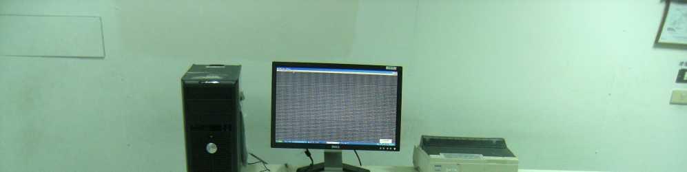
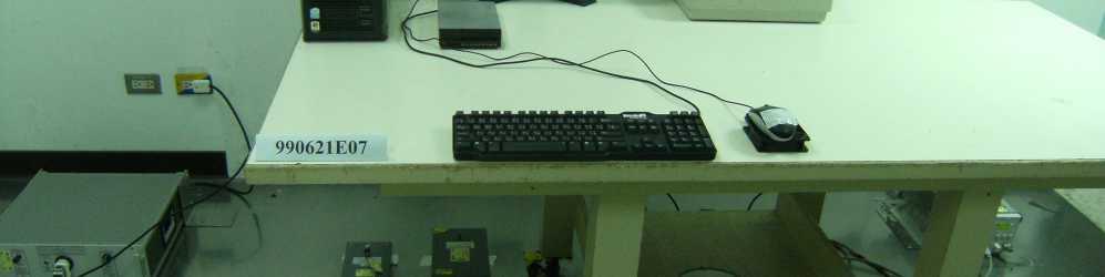
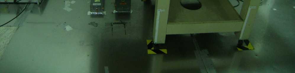
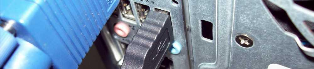
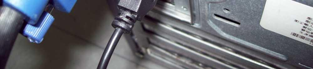
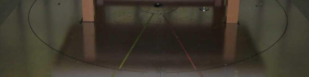
55 6 PHOTOGRAPHS OF THE TEST CONFIGURATION CONDUCTED EMISSION TEST Report No.: CE990621E07 55 Report Format Version 3.0.3


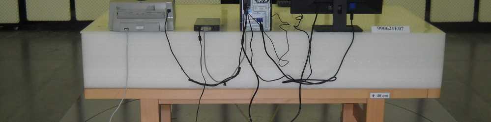
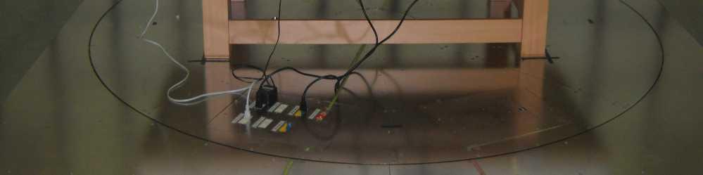
56 RADIATED EMISSION TEST Report No.: CE990621E07 56 Report Format Version 3.0.3


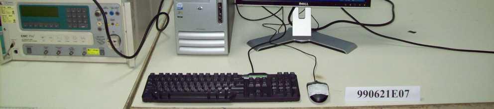


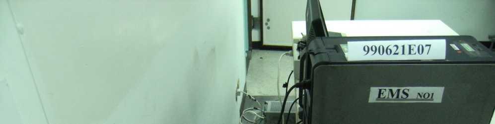
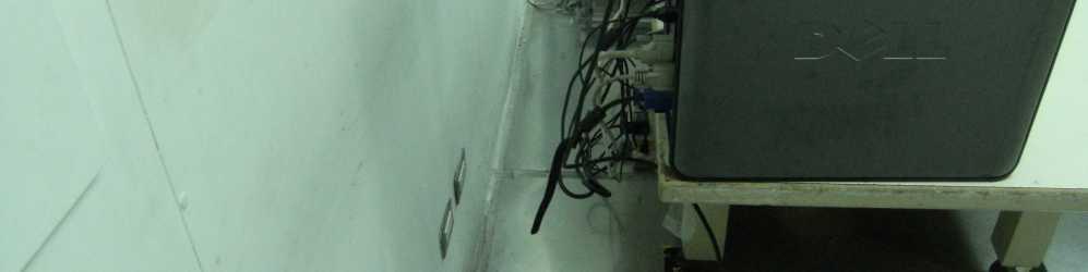
57 HARMONICS EMISSION TEST & VOLTAGE FLUCTUATIONS AND FLICKER TEST ESD TEST Report No.: CE990621E07 57 Report Format Version 3.0.3


58 RS TEST EFT TEST Report No.: CE990621E07 58 Report Format Version 3.0.3


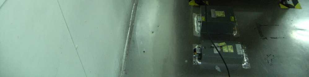
59 SURGE & VOLTAGE DIPS AND INTERRUPTIONS TEST CONDUCTED SUSCEPTIBILITY TEST Report No.: CE990621E07 59 Report Format Version 3.0.3


60 POWER-FREQUENCY MAGNETIC FIELDS TEST Report No.: CE990621E07 60 Report Format Version 3.0.3
61 7 APPENDIX - INFORMATION ON THE TESTING LABORATORIES We, Bureau Veritas Consumer Products Services (H.K.) Ltd., Taoyuan Branch, were founded in 1988 to provide our best service in EMC, Radio, Telecom and Safety consultation. Our laboratories are accredited and approved according to ISO/IEC 17025: Copies of accreditation certificates of our laboratories obtained from approval agencies can be downloaded from our web site: If you have any comments, please feel free to contact us at the following: Linko EMC/RF Lab: Tel: Fax: Hsin Chu EMC/RF Lab: Tel: Fax: Hwa Ya EMC/RF/Safety/Telecom Lab: Tel: Fax: service@adt.com.tw Web Site: The address and road map of all our labs can be found in our web site also. --- END --- Report No.: CE990621E07 61 Report Format Version 3.0.3

62 Page: 1

63 Page: 2


64 Page: 3
65 Page: 4
VCCI TEST REPORT. TESTED : June 22 to 23, 2010 APPLICANT : LOGITECH FAR EAST LTD.
 VCCI TEST REPORT REPORT NO. : V990621E07 MODEL NO. : M-U0026 RECEIVED : June 21, 2010 TESTED : June 22 to 23, 2010 ISSUED : June 24, 2010 APPLICANT : LOGITECH FAR EAST LTD. ADDRESS : #2 Creation Rd. 4,
FCC DoC TEST REPORT. TESTED : Sep. 01 to 02, 2010 APPLICANT : LOGITECH FAR EAST LTD.
 FCC DoC TEST REPORT REPORT NO. : FD990901E04 MODEL NO. : Y-R0016 RECEIVED : Sep. 01, 2010 TESTED : Sep. 01 to 02, 2010 ISSUED DATE : Sep. 07, 2010 APPLICANT : LOGITECH FAR EAST LTD. ADDRESS : #2 Creation
EMC TEST REPORT. ADDRESS : #2 Creation Rd. 4, Science-Based Ind. Park Hsinchu Taiwan, R.O.C.
 EMC TEST REPORT REPORT NO. : RM110613E07 MODEL NO. : M-R0027 RECEIVED : June 13, 2011 TESTED : June 17, 2011 ISSUED : June 22, 2011 APPLICANT : LOGITECH FAR EAST LTD. ADDRESS : #2 Creation Rd. 4, Science-Based
FCC DoC TEST REPORT. ADDRESS : #2 Creation Rd. 4, Science-Based Ind. Park Hsinchu Taiwan, R.O.C.
 FCC DoC TEST REPORT REPORT NO. : FD990811E03 MODEL NO. : A-E0001 RECEIVED : Aug. 11, 2010 TESTED : Aug. 13 to 17, 2010 ISSUED DATE : Aug. 20, 2010 APPLICANT : LOGITECH FAR EAST LTD. ADDRESS : #2 Creation
FCC DoC TEST REPORT. ADDRESS : #2 Creation Rd. 4, Science-Based Ind. Park Hsinchu Taiwan, R.O.C.
 FCC DoC TEST REPORT REPORT NO. : FD981207H01 MODEL NO. : N-I0004 RECEIVED : Dec 07, 2009 TESTED : Dec. 08, 2009 ISSUED: Dec. 14, 2009 APPLICANT : LOGITECH FAR EAST LTD. ADDRESS : #2 Creation Rd. 4, Science-Based
FCC DoC TEST REPORT. ISSUED BY : Bureau Veritas Consumer Products Services (H.K.) Ltd., Taoyuan Branch Hsin Chu Laboratory
 Ltd., Taoyuan Branch Hsin Chu Laboratory") FCC DoC TEST REPORT REPORT NO. : FD110511E05 MODEL NO. : A-00033 RECEIVED : May 11, 2011 TESTED : May 13, 2011 ISSUED: June 30, 2011 APPLICANT : Logitech Inc. ADDRESS : 6505 Kaiser Drive, Fremont, CA 94555
FCC DoC TEST REPORT REPORT NO. : FD110511E05 MODEL NO. : A-00033 RECEIVED : May 11, 2011 TESTED : May 13, 2011 ISSUED: June 30, 2011 APPLICANT : Logitech Inc. ADDRESS : 6505 Kaiser Drive, Fremont, CA 94555
FCC TEST REPORT. ADDRESS: #2 Creation Rd. 4, Science-Based Ind. Park Hsinchu Taiwan, R.O.C.
 FCC TEST REPORT REPORT NO.: RF991014E04 MODEL NO.: M-R0018 FCC ID: JNZMR0018 RECEIVED: Oct. 14, 2010 TESTED: Oct. 19, 2010 ISSUED: Oct. 22, 2010 APPLICANT: LOGITECH FAR EAST LTD. ADDRESS: #2 Creation Rd.
EMC TEST REPORT. Report No.: CE10-LIE040101E
 EMC TEST REPORT Report No.: CE10-LIE040101E Product: LED TUBE Model No.: T10, T8, T5 Applicant: Shenzhen Saiju Electronic Co., Ltd. Address: 2nd. Xianshun Industrial Park, Gushu, Xixiang, Bao an, Shenzhen,
FCC Verification Test Report
 FCC Verification Test Report Report No.: Test Model: FV130424E06E VC-A50, PTC-120 Series Model: VC-X50, VC-X30, VC-501, VC-502, VC-301, VC-302, VC-302X, VC-502X, VC-A50X (where X can be A to Z for marketing
EMC TEST REPORT For MPP SOLAR INC Inverter/ Charger Model Number : PIP 4048HS
 EMC-E20130903E EMC TEST REPORT For MPP SOLAR INC Inverter/ Charger Model Number : PIP 4048HS Prepared for : MPP SOLAR INC Address : 4F, NO. 50-1, SECTION 1, HSIN-SHENG S. RD. TAIPEI, TAIWAN Prepared by
FCC Test Report (15.249)
") FCC Test Report (15.249) Report No.: FCC ID: Test Model: RF150529E01 JNZNR0010 N-R0010 Received Date: May 29, 2015 Test Date: June 04 to 08, 2015 Issued Date: June 16, 2015 Applicant: LOGITECH FAR EAST
FCC Test Report (15.249) Report No.: FCC ID: Test Model: RF150529E01 JNZNR0010 N-R0010 Received Date: May 29, 2015 Test Date: June 04 to 08, 2015 Issued Date: June 16, 2015 Applicant: LOGITECH FAR EAST
FCC TEST REPORT. LAB ADDRESS: No. 47, 14 th Ling, Chia Pau Tsuen, Linko Hsiang 244, Taipei Hsien, Taiwan, R.O.C.
 FCC TEST REPORT REPORT NO.: RF951204L06A MODEL NO.: WRT54G V8 RECEIVED: Jan. 13, 2007 TESTED: Jan. 13 ~ Jan. 16, 2007 ISSUED: Jan. 17, 2007 APPLICANT: Cisco-Linksys LLC ADDRESS: 121 Theory Drive Irvine,
CE EMC TEST REPORT. LAB LOCATION : No. 81-1, Lu Liao Keng, 9 Ling, Wu Lung Tsuen, Chiung Lin Hsiang, Hsin Chu Hsien, Taiwan
 CE EMC TEST REPORT REPORT NO. : CE951115H04B MODEL NO. : MD15 RECEIVED : Nov. 27, 2006 TESTED : Dec. 04 to 27, 2006 ISSUED: March 07, 2007 APPLICANT : CTC UNION TECHNOLOGIES CO., LTD. ADDRESS : 8F, No.
TEST REPORT. Building 6, XinXinTian Industrial Park, XinSha Road, ShaJing, Baoan District, ShenZhen, China. Shenzhen Innokin Technology Co.
 TEST REPORT Applicant Address Shenzhen Innokin Technology Co., Ltd Building 6, XinXinTian Industrial Park, XinSha Road, ShaJing, Baoan District, ShenZhen, China Manufacturer or Supplier Address Product
FCC TEST REPORT (Z-Wave)
") FCC TEST REPORT (Z-Wave) REPORT NO.: RF130927E08E-2 MODEL NO.: FiOS-G1100 FCC ID: 2ABTEG1100 RECEIVED: Sep. 27, 2013 TESTED: Oct. 07 to Dec. 06, 2013 ISSUED: Mar. 21, 2014 APPLICANT: Verizon Online LLC
FCC TEST REPORT (Z-Wave) REPORT NO.: RF130927E08E-2 MODEL NO.: FiOS-G1100 FCC ID: 2ABTEG1100 RECEIVED: Sep. 27, 2013 TESTED: Oct. 07 to Dec. 06, 2013 ISSUED: Mar. 21, 2014 APPLICANT: Verizon Online LLC
EN 55022: 2010+AC:2011 Clause 6.1 Pass. Harmonic Current EN :2006+A1:2009+A2:2009 Class A N/A
 Reference No.: WT12106773-N-S-E Page 2 of 33 1 Test Summary Test Item Mains Terminal Disturbance Voltage, 150KHz to 30MHz Radiation Emission, 30MHz to 1000MHz EMISSION Test Standard Class / Severity Result
Supplemental Transmit Simultaneously Test Report
 Supplemental Transmit Simultaneously Test Report REPORT NO.: RF141003E10-2 MODEL NO.: EX6150 FCC ID: PY314300283 RECEIVED: Oct. 03, 2014 TESTED: Oct. 09 to Dec. 08, 2014 ISSUED: Jan. 12, 2015 APPLICANT:
TEST REPORT. Building 6,XinXinTian Industrial Park, XinSha Road, ShaJing, Baoan District, ShenZhen, China
 TEST REPORT Applicant Address Innokin Technology Co.,Ltd Building 6,XinXinTian Industrial Park, XinSha Road, ShaJing, Baoan District, ShenZhen, China Manufacturer or Supplier Address Product Innokin Technology
EN 55015: 2013 Clause Pass. EN 55015: 2013 Clause Pass. EN 55015: 2013 Clause Pass
 Reference No.: WTD15S0730643E Page 2 of 42 1 Test Summary Test Item Conducted Disturbance at Mains Terminal, 9kHz to 30MHz Radiation electromagnetic disturbance, 9kHz to 30MHz Radiation Emission, 30MHz
FCC Test Report RF141003E10B-1. Report No.: PY FCC ID: EX6150. Test Model: Received Date: Apr. 17, Test Date: Apr. 22 to July 21, 2015
 FCC Test Report Report No.: FCC ID: Test Model: RF141003E10B-1 PY314300283 EX6150 Received Date: Apr. 17, 2015 Test Date: Apr. 22 to July 21, 2015 Issued Date: Aug. 03, 2015 Applicant: NETGEAR, Inc. Address:
CE EMC TEST REPORT VIVOTEK INC.
 CE EMC TEST REPORT REPORT NO.: CE921001R05 MODEL NO.: IP 2112 / IP 2122 RECEIVED: October 16, 2003 TESTED: October 16~ November 03, 2003 APPLICANT: ADDRESS: VIVOTEK INC. 6F, No.192, Lien-Chen Rd., Chung-Ho,
FCC TEST REPORT th Lin, Chiapau Tsun, Linko, Taipei, Taiwan, R.O.C. No. 19, Hwa Ya 2 nd Rd., Kueishan, Taoyuan, Taiwan, R.O.C.
 FCC TEST REPORT REPORT NO.: RF941130L05 MODEL NO.: WAP54G ver. 3.1 RECEIVED: Jan. 23, 2006 TESTED: Jan. 23 ~ Feb. 27, 2006 ISSUED: Mar. 02, 2006 APPLICANT: Cisco-Linksys LLC ADDRESS: 121 Theory Drive Irvine,
CE EMC TEST REPORT. ADDRESS: No. 25, Wu-Gong 6th Rd., Wu Ku Industrial Park, Taipei Hsien, Taiwan, R. O. C.
 CE EMC TEST REPORT REPORT NO.: CE990923D04 MODEL NO.: Y-U0012 RECEIVED: Sep. 23, 2010 TESTED: Sep. 24 ~ 29, 2010 ISSUED: Sep. 30, 2010 APPLICANT: Chicony Electronics Co., Ltd. ADDRESS: No. 25, Wu-Gong
CE EMC TEST REPORT CE940127L06 VIVOTEK INC.
 CE EMC TEST REPORT REPORT NO. : MODEL NO. : CE940127L06 PZ6112, PZ6122, PZ7112, PZ7122, ANC-808V RECEIVED : Jan. 27, 2005 TESTED : Mar. 08 to Apr. 17, 2005 ISSUED : Apr. 18, 2005 APPLICANT : VIVOTEK INC.
FCC 15B Test Report. : BTv4.0 Dual Mode USB Dongle. Address : Thompson Ave. / Lenexa, Kansas / / USA
 FCC 15B Test Report Equipment Model No. Brand Name Applicant : BTv4.0 Dual Mode USB Dongle : BT820 : Laird Technologies : Laird Technologies Address : 11160 Thompson Ave. / Lenexa, Kansas / 66219 / USA
FCC TEST REPORT (RFID)
") FCC TEST REPORT (RFID) REPORT NO.: RF130923D14-2 MODEL NO.: DC-NU2-UMPC FCC ID: 2AA69001 RECEIVED: Sep. 23, 2013 TESTED: Oct. 11 ~ 17, 2013 ISSUED: Oct. 25, 2013 APPLICANT: Capsule Technologie SAS ADDRESS:
FCC TEST REPORT (RFID) REPORT NO.: RF130923D14-2 MODEL NO.: DC-NU2-UMPC FCC ID: 2AA69001 RECEIVED: Sep. 23, 2013 TESTED: Oct. 11 ~ 17, 2013 ISSUED: Oct. 25, 2013 APPLICANT: Capsule Technologie SAS ADDRESS:
EMC REPORT. ShenZhen KY Technology Co.,Ltd. No.369, BaoTian 1st RD, TieGang Industrial Park, Xixiang Town, Baoan District, ShenZhen, PRC.
 Report No.: UNI2016121702ER-01 Page 1 / 30 ShenZhen KY Technology Co.,Ltd EMC REPORT Prepared For: ShenZhen KY Technology Co.,Ltd Product Name: Smart bracelet No.369, BaoTian 1st RD, TieGang Industrial
FCC TEST REPORT. SendFar Technology Co., Ltd.
 FCC TEST REPORT REPORT NO.: RF921021R02 MODEL NO.: WPC-3110 RECEIVED: October 21, 2003 TESTED: November 14 ~ November 16, 2003 APPLICANT: ADDRESS: SendFar Technology Co., Ltd. 15FL., NO.866-2, JUNGJENG
EMC TEST REPORT. for. Coliy Technology Co.,Ltd. Fluxgate Gaussmeter
 Page 1 of 48 EMC TEST REPORT for Coliy Technology Co.,Ltd. Fluxgate Gaussmeter Prepared for : Coliy Technology Co.,Ltd. Address : Block B,9 th Floor,Xinzhongtai Business Building,Gushu 2nd Road,Xi Town,Bao
EMC TEST REPORT. according to
 EMC TEST REPORT according to European Standard EN 55022:2006/A1:2007 Class B, EN 61000-3-2:2006, EN 61000-3-3:1995/A1:2001/A2:2006, EN 55024:1998/A1:2001/A2:2003 (IEC 61000-4-2:Edition 1.2:2001-04, IEC
TEST REPORT... 1 CONTENT...
 CONTENT TEST REPORT... 1 CONTENT... 2 1 TEST RESULTS SUMMARY... 3 2 EMC RESULTS CONCLUSION... 4 3 LABORATORY MEASUREMENTS... 6 4 EMI TEST... 7 4.1 CONTINUOUS CONDUCTED DISTURBANCE VOLTAGE TEST... 7 4.2
Harmonic Current emission EN :2014 Class A Pass. Voltage Fluctuation and Flicker EN :2013 Clause 5 Pass
 Reference No.: WTS15F0323845E Page 2 of 33 1 Test Summary Test Item Mains Terminal Disturbance Voltage, 148.5kHz to 30MHz Disturbance Power, 30MHz to 300MHz Discontinuous Disturbance (Click) Radiated Emission,
ITUNER NETWORKS CORPORATION EMC REPORT Fremont Blvd. Fremont, CA
 Shenzhen BST Technology Co., Ltd. ITUNER NETWORKS CORPORATION EMC REPORT Prepared For : ITUNER NETWORKS CORPORATION 47801 Fremont Blvd. Fremont, CA. 94538 Product Name: PicoPSU-150 Trade Name: PicoPSU
Discontinuous Disturbance (Click) EN :2006+A1:2009+A2:2011 Clause N/A** Radiated Emission, 30MHz to 1000MHz
 EN :2006+A1:2009+A2:2011 Clause N/A** Radiated Emission, 30MHz to 1000MHz") Reference No.: WTN13F0706038E Page 2 of 40 1 Test Summary Test Item Mains Terminal Disturbance Voltage, 148.5kHz to 30MHz Disturbance Power, 30MHz to 300MHz EMISSION Test Standard Class / Severity Result
Reference No.: WTN13F0706038E Page 2 of 40 1 Test Summary Test Item Mains Terminal Disturbance Voltage, 148.5kHz to 30MHz Disturbance Power, 30MHz to 300MHz EMISSION Test Standard Class / Severity Result
TEST SUMMARY. Prüfbericht - Nr.: Test Report No.: Seite 2 von 27. Page 2 of 27
 15072768 001 Seite 2 von 27 Page 2 of 27 TEST SUMMARY 4.1.1 HARMONICS ON AC MAINS 4.1.2 VOLTAGE CHANGES, VOLTAGE FLUCTUATIONS AND FLICKER ON AC MAINS 4.1.3 MAINS TERMINAL CONTINUOUS DISTURBANCE VOLTAGE
Equipment : AC/DC ADAPTER Test Model No. : ADP-90MD H Applicant : DELTA ELECTRONICS, INC. Test Report No. : CE130910D06
 Equipment : AC/DC ADAPTER Test Model No. : ADP-90MD H Applicant : DELTA ELECTRONICS, INC. Test Report No. : CE130910D06 We, Bureau Veritas Consumer Products Services (H.K.) Ltd., Taoyuan Branch, declare
TEST REPORT. The submitted sample of the above equipment has been tested for according to the requirements of the following standards:
 TEST REPORT Applicant Address Innokin Technology Co., Ltd Building 6, XinXinTian Industrial Park, XinSha Road, ShaJing, Baoan District, ShenZhen, China Manufacturer or Supplier Address Product Innokin
RADIO TEST REPORT (AS/NZS 4268)
") RADIO TEST REPORT (AS/NZS 4268) REPORT NO.: RC991014E04 MODEL NO.: M-R0018 RECEIVED: Oct. 14, 2010 TESTED: Oct. 19, 2010 ISSUED: Oct. 25, 2010 APPLICANT: LOGITECH FAR EAST LTD. ADDRESS: #2 Creation Rd.
RADIO TEST REPORT (AS/NZS 4268) REPORT NO.: RC991014E04 MODEL NO.: M-R0018 RECEIVED: Oct. 14, 2010 TESTED: Oct. 19, 2010 ISSUED: Oct. 25, 2010 APPLICANT: LOGITECH FAR EAST LTD. ADDRESS: #2 Creation Rd.
CE EMC Test Report GUANGZHOU DMKEMOTOR CO. LTD
 CE REPORT CE EMC Test Report Equipment under Test: Model /Type: Applicant: Address: Manufacturer: Address: Laboratory: Address: Report Number Brush D.C. Motor D5D120-24GU D2D10-12GN, D2D10-24GN, D2D10-36GN,
VCCI TEST REPORT. According to. Class B ITE. Equipment : USB video camera
 VCCI TEST REPORT According to Class B ITE Equipment : USB video camera Model No. : V-U0011 Applicant : Logitech Far East Ltd. 2 Creation Road IV, Science-Based Ind. Park, Hsinchu, Taiwan. The test result
Shenzhen Toby Technology Co., Ltd. EMC Test Report. Report No.: TB-EMC Page: 1 of 20
 Shenzhen Toby Technology Co., Ltd. Report No.: TB-EMC125641 Page: 1 of 20 EMC Test Report Application No. : TB12114299 Applicant : Newmb Technology Co., Ltd. Equipment Under Test (EUT) EUT Name : USB HUB
Test Report. Guangdong East Power Co., Ltd. Fully Automatic AC Voltage Regulator. Brand Name:
 Test Report Applicant: Product Name: Brand Name: Model No.: Guangdong East Power Co., Ltd. Fully Automatic AC Voltage Regulator EAST ZTY-30KVA Date of Receipt : Aug. 30, 2013 Date of Test: Sep. 03, 2013
VCCI TEST REPORT. According to. V-3/ , TECHNICAL REQUIREMENTS, Class B ITE. Equipment : USB video camera. Model No. : V-U0017 / V-U0021
 VCCI TEST REPORT According to V-3/2009.04, TECHNICAL REQUIREMENTS, Class B ITE Equipment : USB video camera Model No. : V-U0017 / V-U0021 Applicant : Logitech Far East Ltd. 2 Creation Road IV, Science-Based
TEST SUMMARY. Prüfbericht - Nr.: Test Report No.: Seite 2 von 25. Page 2 of 25
 15072259 001 Seite 2 von 25 Page 2 of 25 TEST SUMMARY 4.1.1 HARMONICS ON AC MAINS 4.1.2 VOLTAGE FLUCTUATIONS ON AC MAINS 4.1.3 MAINS TERMINAL CONTINUOUS DISTURBANCE VOLTAGE 4.1.4 DISCONTINUOUS INTERFERENCE
TEST REPORT. Report No. : EM/2008/80003 Page : 1 of 54
 Equipment Under Test Brand Name Model No. Added Model(s) Applicant Address of Applicant Page : 1 of 54 TEST REPORT : AC Servo Motor : Kingservo : AC 400W servo motor : N/A : Ho Fo Automation CO., LTD :
EMC Test Report For Changzhou Airwheel Technology Co.,Ltd. Airwheel Model: A6S,A6,A6P,A6PS,A6T,A6TS
 EMC Test Report For Changzhou Airwheel Technology Co.,Ltd. Airwheel Model: A6S,A6,A6P,A6PS,A6T,A6TS Prepared For : Prepared By : Changzhou Airwheel Technology Co.,Ltd. Fl.5, East of No. 10 Building, high-tech
APPLICATION FOR EMC DIRECTIVE. On Behalf of. Shenzhen Qinhan Lighting Co., Ltd. led flood light. Trade Name:
 APPLICATION FOR EMC DIRECTIVE On Behalf of Shenzhen Qinhan Lighting Co., Ltd led flood light Trade Name: Model: QH-TGC-400W, QH-TGC-300W, QH-TGC-500W, QH-TGC-800W, QH-TGC-1000W Prepared For : Shenzhen
CE-EMC TEST REPORT. Prepared for : T&T Assoociates London LTD Suite#306 CityGate House, Bussinedd Centre Stratford, Romford Road, London
 CE-EMC TEST REPORT Prepared for : T&T Assoociates London LTD Suite#306 CityGate House, Bussinedd Centre Stratford, 246-250 Romford Road, London Product: CCTV Camera Trade Name: Model Name: INNOVEXS IPBQH20HH205,
Prepared for Address. : KST DIGITAL TECHNOLOGY LIMITED : No.226, Pangu Street, Meixian, Meizhou, Guangdong. Prepared by
 EMC TEST REPORT For KST DIGITAL TECHNOLOGY LIMITED Coreless Servo Model No.: X12-508 Additional Model No.: DS215MG, DS315MG, DS213MG, DS313MG, DS12C, DS12T, X12-306 Prepared for Address : KST DIGITAL TECHNOLOGY
FCC TEST REPORT (15.407)
") FCC TEST REPORT (15.407) REPORT NO.: RF141003E10-1 MODEL NO.: EX6150 FCC ID: PY314300283 RECEIVED: Oct. 03, 2014 TESTED: Oct. 09 to Dec. 09, 2014 ISSUED: Jan. 12, 2015 APPLICANT: NETGEAR, Inc. ADDRESS:
FCC TEST REPORT (15.407) REPORT NO.: RF141003E10-1 MODEL NO.: EX6150 FCC ID: PY314300283 RECEIVED: Oct. 03, 2014 TESTED: Oct. 09 to Dec. 09, 2014 ISSUED: Jan. 12, 2015 APPLICANT: NETGEAR, Inc. ADDRESS:
EMC TEST REPORT. Report No. : EM/2004/10096 Page : 1 of 19
 EMC TEST REPORT Page : 1 of 19 Equipment Under Test Model No. Applicant Address of Applicant : Bluetooth Headset : FB-HS01 : Formosa Teletek Corporation : 358, Huaya 2 nd Rd., Gueishan shiang, Taoyuan,
EMC TEST REPORT for LEDELS LIGHTING CO., LTD. LED module Model No. : LL-F12T4815X6B
 Page 1 of 27 Report No. R011412016E-1 EMC TEST REPORT for LEDELS LIGHTING CO., LTD LED module Model No. : LL-F12T4815X6B Prepared for : LEDELS LIGHTING CO., LTD Address : 5F, Block C, Mingjinhai Ind. Park,
Overview of EMC Regulations and Testing. Prof. Tzong-Lin Wu Department of Electrical Engineering National Taiwan University
 Overview of EMC Regulations and Testing Prof. Tzong-Lin Wu Department of Electrical Engineering National Taiwan University What is EMC Electro-Magnetic Compatibility ( 電磁相容 ) EMC EMI (Interference) Conducted
ELECTRONICS TESTING CENTER(ETC), TAIWAN
, TAIWAN") File No. : 06-03-RBF-111-01 EMC TESTING DEPARTMENT II Page: 1 / 35 TEST REPORT Responsible Party Manufacturer Description of Product Trade Name : Huan Vu Enterprise Co., Ltd. : Huan Vu Enterprise Co.,
File No. : 06-03-RBF-111-01 EMC TESTING DEPARTMENT II Page: 1 / 35 TEST REPORT Responsible Party Manufacturer Description of Product Trade Name : Huan Vu Enterprise Co., Ltd. : Huan Vu Enterprise Co.,
EMC TEST REPORT for SHENZHEN MUST ENERGY TECHNOLOGY CO., LTD
 Page 1 of 45 Report No. R011607240E EMC TEST REPORT for SHENZHEN MUST ENERGY TECHNOLOGY CO., LTD INVERTER CHARGER Model No.: PV35-4K DC24V MPK, PV35-4K DC48V MPK, PV35-5K DC48V MPK, PV35-6K DC48V MPK Prepared
EMC TEST REPORT. Report No.: TS EME Model No.: 33XR-A Issued Date: Jan. 08, 2009
 Page 1 of 18 EMC TEST REPORT Report No.: TS08100063-EME Model No.: 33XR-A Issued Date: Jan. 08, 2009 Applicant: Test Method/ Standard: Test By: FLUKE CORP. 6920 Seaway Blvd, M/S 266D Everett, WA 98203
EMC TEST REPORT For ShenZhen ZhangQing Electronic LTD poe tester Model No.: WS POE Tester/Detector Additional Model No: Please Refer to Page 8
 EMC TEST REPORT For ShenZhen ZhangQing Electronic LTD poe tester Model No.: WS POE Tester/Detector Additional Model No: Please Refer to Page 8 Prepared for Address : ShenZhen ZhangQing Electronic LTD :
TEST REPORT. Table of Contents
 Page:2 of 24 Table of Contents 1. DOCUMENT POLICY AND TEST STATEMENT... 3 1.1 DOCUMENT POLICY...3 1.2 TEST STATEMENT...3 2. DESCRIPTION OF EUT AND TEST MODE... 4 2.1 GENERAL DESCRIPTION OF EUT...4 2.2
CE TEST CERTIFICATION
 according to Certification No.: E5NC004 European Standard EN 61000-6-4:2001 EN 61000-3-2: 2000, EN 61000-3-3:1995/A1:2001 and EN 61000-6-2:2001 ( IEC 61000-4-2:1995/A1:1998, IEC 61000-4-3: 1995/A1:1998,
1 SUMMARY OF STANDARDS AND RESULTS
 1 SUMMARY OF STANDARDS AND RESULTS 1.1 Description of Standards and Results The EUT have been tested according to the applicable standards as referenced below: EMISSION Description of Test Item Standard
EMC REPORT DONGGUAN FIT-WATCH CO., LTD. 18#,Hedong No.1 road,jinsha village,changan town, Dongguan City, Guangdong Province.
 DONGGUAN FIT-WATCH CO., LTD. EMC REPORT Prepared For : DONGGUAN FIT-WATCH CO., LTD. 18#,Hedong No.1 road,jinsha village,changan town, Dongguan City, Guangdong Province Product Name : Trade Name : Model
RADIO TEST REPORT (AS/NZS 4268)
") RADIO TEST REPORT (AS/NZS 4268) REPORT NO.: RC990901E04 MODEL NO.: Y-R0016 RECEIVED: Sep. 01, 2010 TESTED: Sep. 01 to 02, 2010 ISSUED: Sep. 08, 2010 APPLICANT: LOGITECH FAR EAST LTD. ADDRESS: #2 Creation
RADIO TEST REPORT (AS/NZS 4268) REPORT NO.: RC990901E04 MODEL NO.: Y-R0016 RECEIVED: Sep. 01, 2010 TESTED: Sep. 01 to 02, 2010 ISSUED: Sep. 08, 2010 APPLICANT: LOGITECH FAR EAST LTD. ADDRESS: #2 Creation
EMC TEST REPORT For. Shenzhen Ruideou Keji Youxian Gongsi. Shenzhen Ruideou Keji Youxian Gongsi
 EMC TEST REPORT For Shenzhen Ruideou Keji Youxian Gongsi Product Name: Trademark: Milligram Scale WAOAW Model Number: W-01-50 Prepared For : Address: Prepared By : Address: Shenzhen Ruideou Keji Youxian
FCC TEST REPORT. ISSUED BY: Bureau Veritas Consumer Products Services (H.K.) Ltd., Taoyuan Branch
 Ltd., Taoyuan Branch") FCC TEST REPORT REPORT NO.: RF971218L04 MODEL NO.: ESR-9753 (Refer to item 3.1 for more detail) RECEIVED: Dec. 18, 2008 TESTED: Dec. 22 ~ Dec. 25, 2008 ISSUED: Dec. 31, 2008 APPLICANT: Senao Networks Inc.
FCC TEST REPORT REPORT NO.: RF971218L04 MODEL NO.: ESR-9753 (Refer to item 3.1 for more detail) RECEIVED: Dec. 18, 2008 TESTED: Dec. 22 ~ Dec. 25, 2008 ISSUED: Dec. 31, 2008 APPLICANT: Senao Networks Inc.
CE TEST CERTIFICATION
 Certification No.: E5DC001 according to European Standard EN 61000-6-4:2001 EN 61000-3-2: 2000, EN 61000-3-3:1995/A1:2001 and EN 61000-6-2:2001 ( IEC 61000-4-2:1995/A1:1998, IEC 61000-4-3: 1995/A1:1998,
Discontinuous Disturbance (Click) EN : 2011 Clause Pass Radiated Emission, 30MHz to 1000MHz
 EN : 2011 Clause Pass Radiated Emission, 30MHz to 1000MHz") Reference No.: WTU15U0933879E Page 2 of 45 1 Test Summary Test Item Mains Terminal Disturbance Voltage, 148.5kHz to 30MHz Disturbance Power, 30MHz to 300MHz EMISSION Test Standard Class / Severity Result
Reference No.: WTU15U0933879E Page 2 of 45 1 Test Summary Test Item Mains Terminal Disturbance Voltage, 148.5kHz to 30MHz Disturbance Power, 30MHz to 300MHz EMISSION Test Standard Class / Severity Result
Test Report GUANGDONG EAST POWER CO., LTD
 Test Report Applicant: Product Name: Brand Name: Model No.: GUANGDONG EAST POWER CO., LTD Online High Frequency UPS EAST EA906IIRTS, EA906IIRTH Date of Receipt : Feb. 26, 2014 Date of Test: Mar. 24, 2014
TEST SUMMARY Seite 2 von 27. Prüfbericht - Nr.: Test Report No HARMONICS ON AC MAINS RESULT: Passed
 17035561 001 Seite 2 von 27 Page 2 of 27 TEST SUMMARY 5.1.1 HARMONICS ON AC MAINS RESULT: Passed 5.1.2 VOLTAGE FLUCTUATIONS ON AC MAINS RESULT: Passed 5.1.3 TERMINAL CONTINUOUS DISTURBANCE VOLTAGE AT RESULT:
CE EMC Test Certification
 Certification No.: EC57C001 CE EMC Test Certification According to European Standard EN 55022:1998/A1:2000/A2:2003 Class A, EN 61000-3-2: 2000, EN 61000-3-3:1995/A1:2001 and EN 55024:1998/A1:2001/A2:2003
for Issued for Supremevalue Technology CO., Ltd 4/F,A4 Bldg.,Yinlong Industrial Park,292# Shenshan Rd,518116, Longgang District,Shenzhen,China.
 EMC TEST REPORT for Product: Car Charger Trade Mark: MEKNIC Model: SV-PC01,SV-PC02,SV-PC03,SV-PC04,SV-PC05, SV-PC06,SV-PC07,SV-PC08,SV-PC09,SV-PC10, SV-PC11,SV-PC12,SV-PC13,SV-PC14,SV-PC15, SV-PC16,SV-PC17,SV-PC18,SV-PC19,SV-PC20
CE EMC TEST REPORT. APPLICANT: LSI Corporation ADDRESS: 3718 N. Rock Road Wichita, KS USA
 CE EMC TEST REPORT REPORT NO.: CE990610C19A MODEL NO.: 25121 (refer to 3.1 for more details) RECEIVED: Jun. 10, 2010 TESTED: Jun. 18 ~ Jun. 24, 2010 ISSUED: Dec. 07, 2012 APPLICANT: LSI Corporation ADDRESS:
EMC TEST REPORT for : DONGGUAN EVER DEVELOPMENT ELECTRONIC CO., Electronic calculator Model No.: KF15758
 Page 1 of 20 Report No. R011604553E EMC TEST REPORT for DONGGUAN EVER DEVELOPMENT ELECTRONIC CO., LTD. Electronic calculator Model No.: KF15758 Prepared for Address Prepared by Address : DONGGUAN EVER
FCC 47 CFR PART 15 SUBPART B
 FCC 47 CFR PART 15 SUBPART B TEST REPORT For DC TO DC CONVERTER Model : D100 Series Issued for MicroPower Direct, LLC 232 Tosca Drive Stoughton, MA02072 U.S.A. Issued by Compliance Certification Services
EMC TEST REPORT. For. Switching Mode Power Adaptor. Model No.: 9W/14.4V/EU(18V/1.0A), 19W/14.4V/EU(12V/1.5A)
, 19W/14.4V/EU(12V/1.5A)") EMC TEST REPORT For Company Limited Liability «Faraday Electronics» Switching Mode Power Adaptor Model No.: 9W/14.4V/EU(18V/1.0A), 19W/14.4V/EU(12V/1.5A) Prepared For : Company Limited Liability «Faraday
EMC TEST REPORT For Company Limited Liability «Faraday Electronics» Switching Mode Power Adaptor Model No.: 9W/14.4V/EU(18V/1.0A), 19W/14.4V/EU(12V/1.5A) Prepared For : Company Limited Liability «Faraday
EMC Test Report. Report Number: M030826
 Page 1 of 36 EMC Technologies Pty Ltd ABN 82 057 105 549 57 Assembly Drive Tullamarine Victoria Australia 3043 Ph: + 613 9335 3333 Fax: + 613 9338 9260 email: melb@emctech.com.au EMC Test Report Report
FCC 15B Test Report. : Bluetooth 4.2 Dual Mode USB HCI Module (Refer to item for more details) (Refer to item for more details)
 (Refer to item for more details)") FCC 15B Test Report Equipment Model No. Brand Name Applicant Address Standard : Bluetooth 4.2 Dual Mode USB HCI Module (Refer to item 1.1.1 for more details) : BT850-SA (Refer to item 1.1.1 for more details)
FCC 15B Test Report Equipment Model No. Brand Name Applicant Address Standard : Bluetooth 4.2 Dual Mode USB HCI Module (Refer to item 1.1.1 for more details) : BT850-SA (Refer to item 1.1.1 for more details)
EMC TEST REPORT. NORTE SIRIUS ENTERPRISE CO., LTD , Shin-Sheng St., Chung-Ho Dist, New Taipei City, Taiwan
 Page 1 of 32 EMC TEST REPORT Report No.: TS11020117-EME Model No.: NS-PSE, NS-POINTED, NS-PSQUARE, NS-PF-S, NS-PT, NS-PR, NS-PU, NS-PF-H, NS-BALIBA, NS-FLEXMA Issued Date: Mar. 01, 2011 Applicant: NORTE
SUZHOU MAILI ELECTRICAL APPLIANCE CO., LTD NO.666,JIANLIN RD, XUGUAN SUBAREA, SUZHOU HIGH-TECH ZONE
 EMC TEST REPORT For SUZHOU MAILI ELECTRICAL APPLIANCE CO., LTD Product Name: Pure sine wave power inverter Trademark: Model : Prepared For : Address: Prepared By : Address: ML-1000W ML-300W---ML-8000W.
TEST REPORT. Table of Contents
 Page:2 of 35 Table of Contents 1. DOCUMENT POLICY AND TEST STATEMENT... 4 1.1 DOCUMENT POLICY...4 1.2 TEST STATEMENT...4 1.3 EUT MODIFICATION...4 2. DESCRIPTION OF EUT AND TEST MODE... 5 2.1 GENERAL DESCRIPTION
Guangdong East Power Co., Ltd. Uninterruptible Power Systems
 Test Report Applicant: Product Name: Brand Name: Model No.: Guangdong East Power Co., Ltd. Uninterruptible Power Systems EAST EA8806, EA8804 Date of Receipt : Nov. 01, 2012 Date of Test: Nov. 03, 2012
EMC TEST REPORT. For. Boardcon Technology Limited. MINI9G45 Computer on Module. Model No. : MINI9G45
 REPORT NO. PRSZ15110502E EMC TEST REPORT For Boardcon Technology Limited. MINI9G45 Computer on Module Model No. : MINI9G45 Prepared For : Boardcon Technology Limited. : Room 702, Hua Feng Xin An Business
EMC VERIFICATION SUMMARY Report No.: SZHH
 EMC VERIFICATION SUMMARY Toy ITE Others Additional Models: 0801 to 0899 INCLUSIVE, 0804, 0804W, 0805, 0806, 0807, 0808, 0809, 0811, 0811W, 0812, 0813, 0814,0815, 0816, 0817,0817 ROOM 619, 6/F. PENINSULA
EMC TEST REPORT. According to
 EMC TEST REPORT According to EN 55022:2006/A1:2007 (Class B) EN 55024 : 1998/ A1:2001/ A2:2003 EN 61000-3-2 : 2006/A1:2009/A2:2009 IEC 61000-4-2 : 2008 EN 61000-3-3 : 2008 IEC 61000-4-3 : 2010 IEC 61000-4-4
CE EMC TEST REPORT. MANUFACTURER : TP-Link Technologies Co., Ltd.
 CE EMC TEST REPORT REPORT NO. : EH6D2816-01 MODEL NO. : Archer VR2800 RECEIVED DATE : Dec. 28, 2016 FINAL TESTED DATE : Mar. 31, 2017 ISSUED DATE : Apr. 06, 2017 TEST STANDARD : EN 301 489-1 V1.9.2 (2011-09),
EMC TEST REPORT. : 4F, No. 50-1, Section 1, Hsin-Sheng S. Rd. Taipei, Taiwan. Taiwan
 EMC TEST REPORT For MPP SOLAR INC Model Number: PIP 2424MS Prepare for Address : MPP Solar Inc : 4F, No. 50-1, Section 1, Hsin-Sheng S. Rd. Taipei, Taiwan Prepare by Address : MPP Solar In : 4F, No. 50-1,
FCC TEST REPORT (WLAN )
") FCC TEST REPORT (WLAN 15.247) REPORT : RF130923D14 MODEL : DC-NU2-UMPC FCC ID: 2AA69001 RECEIVED: Sep. 23, 2013 TESTED: Sep. 24 ~ Oct. 24, 2013 ISSUED: Oct. 25, 2013 APPLICANT: Capsule Technologie SAS
FCC TEST REPORT (WLAN 15.247) REPORT : RF130923D14 MODEL : DC-NU2-UMPC FCC ID: 2AA69001 RECEIVED: Sep. 23, 2013 TESTED: Sep. 24 ~ Oct. 24, 2013 ISSUED: Oct. 25, 2013 APPLICANT: Capsule Technologie SAS
EMC TEST REPORT For DONGHUA ELECTRIC STOCK CO., LTD. OF ZHEJIANG
 EMC TEST REPORT For DONGHUA ELECTRIC STOCK CO., LTD. OF ZHEJIANG SWITCHING POWER SUPPLY Model No. HSM-50-12~48 HSM-15-5~24, HSM-35-12~48. : DONGHUA ELECTRIC STOCK CO., LTD. OF ZHEJIANG : No.3 Tengfei Road,
TEST REPORT. Product: Thermo-Hygrometer Model No.: FL-201, FL-201W Trade mark: N/A Report No.: TCT151014E001 Issued Date: Oct. 15, 2015.
 TEST REPORT Product: Thermo-Hygrometer Model No.: FL-201, FL-201W Trade mark: N/A Report No.: TCT151014E001 Issued Date: Oct. 15, 2015 Issued for: Shenzhen Flus Technology Co., Ltd 3rd Floor, Lantian Building,
TEST REPORT. Table of Contents
 Page:2 of 28 Table of Contents 1. DOCUMENT POLICY AND TEST STATEMENT... 3 1.1 DOCUMENT POLICY... 3 1.2 TEST STATEMENT... 3 2. DESCRIPTION OF EUT AND TEST MODE... 4 2.1 GENERAL DESCRIPTION OF EUT... 4 2.2
CONFORMANCE TEST REPORT FOR EN /-6
 CONFORMANCE TEST REPORT FOR EN 301489-1/-6 Client: Product: Model: Manufacturer/supplier: Aztech Systems Limited DECT Phone H315-S1 (FP) Aztech Systems Limited Date test item received: 2006/05/09 Date
2620 Modular Measurement and Control System
 European Union (EU) Council Directive 89/336/EEC Electromagnetic Compatibility (EMC) Test Report 2620 Modular Measurement and Control System Sensoray March 31, 2006 April 4, 2006 Tests Conducted by: ElectroMagnetic
FCC SUPPLEMENTARY TEST REPORT
 FCC SUPPLEMENTARY TEST REPORT REPORT NO.: RF960612H07C MODEL NO.: WRP400 RECEIVED: Apr. 24, 2009 TESTED: June 05 to July 10, 2009 ISSUED: July 13, 2009 APPLICANT: Cisco-Linksys LLC ADDRESS: 121 Theory
CE EMC TEST REPORT. Model Name: JZH-RF898B JZH-RX898B Report No.: BCTC E. Prepared for
 Shenzhen BCTC Technology Co., Ltd. Report No.: BCTC-160608172-2E CE EMC TEST REPORT Product: Fishing bite alarm Trade Name: Model Name: JZH-RF898B JZH-RX898B Report No.: BCTC-160608172-2E Prepared for
Test Report. Ningbo Goldmore Industrial Co.,Ltd.
 Test Report Applicant: Ningbo Goldmore Industrial Co.,Ltd. Product Name: Brand Name: Model No.: LED CAMPING LANTERN with FAN N/A XJH-8098 Date of Receipt : Sep. 23, 2014 Date of Test: Sep. 25, 2014 Date
FCC TEST REPORT (15.407)
") FCC TEST REPORT (15.407) REPORT : RF141108C01-1 MODEL : AP 100X FCC ID: 2ACTO-AP100X RECEIVED: Nov. 08, 2014 TESTED: Nov. 19 ~ Nov. 26, 2014 ISSUED: Dec. 02, 2014 APPLICANT: Sophos Ltd ADDRESS: The Pentagon,Abingdon,OX14
FCC TEST REPORT (15.407) REPORT : RF141108C01-1 MODEL : AP 100X FCC ID: 2ACTO-AP100X RECEIVED: Nov. 08, 2014 TESTED: Nov. 19 ~ Nov. 26, 2014 ISSUED: Dec. 02, 2014 APPLICANT: Sophos Ltd ADDRESS: The Pentagon,Abingdon,OX14
Test Report Report No.: G150424B02-03EN Date: May. 07, 2015 Page 1 of 49
 Test Report Report No.: G150424B02-03EN Date: May. 07, 2015 Page 1 of 49 The following information was submitted and identified by/on behalf of the client as: Applicant : Ningbo Shanhuang Electric Appliance
FCC C2PC Test Report
 FCC C2PC Test Report FCC ID Equipment Model No. Brand Name Applicant : SQGBT800 : BTv4.0 Dual Mode USB Dongle : BT820 : Laird Technologies : Laird Technologies Address : 11160 Thompson Ave. / Lenexa, Kansas
CE-EMC TEST REPORT. Test report On Behalf of MAZi Security Systems GmbH For TVI CCTV Camera Model No.: TDE-11S; Serial Model See Page 2
 Page 1 of 55 CE-EMC TEST REPORT Test report On Behalf of MAZi Security Systems GmbH For TVI CCTV Camera Model No.: TDE-11S; Serial Model See Page 2 Prepared for : MAZi Security Systems GmbH Ostwall 216,
CE/EMC TEST REPORT. For HK QNOVATOR TECHNOLOGY CO.,LIMITED GS02-M X1, BL02, GS01, GS01-M, GS02, GS03, GS04, GS05, GS06, GS07, GS08, GS09, GS10
 CE/EMC TEST REPORT For HK QNOVATOR TECHNOLOGY CO.,LIMITED Product Name: Vacuum Tube Amplifier Trademark: Model Number: Prepared For: Address: Gemtune GS02-M X1, BL02, GS01, GS01-M, GS02, GS03, GS04, GS05,
EMC test report AU01+E04
 Customer: Altuflevskoye shosse,h.48,bld.1pr.1,room39 Moscow,127566 Russia EMC test report 130504-AU01+E04 This test report may not be copied or published in a part without the written authorization of