CE EMC TEST REPORT. APPLICANT: LSI Corporation ADDRESS: 3718 N. Rock Road Wichita, KS USA
|
|
|
- Opal Chase
- 6 years ago
- Views:
Transcription
 Ltd., Taoyuan Branch LAB ADDRESS: No.")
1 CE EMC TEST REPORT REPORT NO.: CE990610C19A MODEL NO.: (refer to 3.1 for more details) RECEIVED: Jun. 10, 2010 TESTED: Jun. 18 ~ Jun. 24, 2010 ISSUED: Dec. 07, 2012 APPLICANT: LSI Corporation ADDRESS: 3718 N. Rock Road Wichita, KS USA ISSUED BY: Bureau Veritas Consumer Products Services (H.K.) Ltd., Taoyuan Branch LAB ADDRESS: No. 19, Hwa Ya 2nd Rd., Wen Hwa Tsuen, Kwei Shan Hsiang, Taoyuan Hsien 333, Taiwan This report should not be used by the client to claim product certification, approval, or endorsement by TAF or any government agencies. This report is for your exclusive use. Any copying or replication of this report to or for any other person or entity, or use of our name or trademark, is permitted only with our prior written permission. This report sets forth our findings solely with respect to the test samples identified herein. The results set forth in this report are not indicative or representative of the quality or characteristics of the lot from which a test sample was taken or any similar or identical product unless specifically and expressly noted. Our report includes all of the tests requested by you and the results thereof based upon the information that you provided to us. You have 60 days from date of issuance of this report to notify us of any material error or omission caused by our negligence, provided, however, that such notice shall be in writing and shall specifically address the issue you wish to raise. A failure to raise such issue within the prescribed time shall constitute your unqualified acceptance of the completeness of this report, the tests conducted and the correctness of the report contents. Unless specific mention, the uncertainty of measurement has been explicitly taken into account to declare the compliance or non-compliance to the specification Report No.: CE990610C19A 1 of 98 Report Format Version 5.0.1
2 Table of Contents RELEASE CONTROL RECORD CERTIFICATION SUMMARY OF TEST RESULTS MEASUREMENT UNCERTAINTY GENERAL INFORMATION GENERAL DESCRIPTION OF EUT THE PHOTO OF LOCATION OF EUT IN HOST THE PHOTO OF TOP AND BOTTOM SIDE OF EUT THE PHOTO OF NOISE SOURCES OF EUT THE CIRCUIT BLOCK DIAGRAM OF EUT ID LABEL SPECIFICATION DESCRIPTION OF TEST MODES GENERAL DESCRIPTION OF THE APPLIED STANDARD DESCRIPTION OF SUPPORT UNITS CONFIGURATION OF SYSTEM UNDER TEST EMISSION TEST CONDUCTED EMISSION MEASUREMENT LIMITS OF CONDUCTED EMISSION MEASUREMENT TEST INSTRUMENTS TEST PROCEDURE DEVIATION FROM TEST STANDARD TEST SETUP EUT OPERATING CONDITIONS TEST RESULTS NOISE FLOOR MEASUREMENT RADIATED EMISSION MEASUREMENT LIMITS OF RADIATED EMISSION MEASUREMENT TEST INSTRUMENTS TEST PROCEDURE DEVIATION FROM TEST STANDARD TEST SETUP EUT OPERATING CONDITIONS TEST RESULTS NOISE FLOOR MEASUREMENT Report No.: CE990610C19A 2 of 98 Report Format Version 5.0.1
3 4.3 HARMONICS CURRENT MEASUREMENT LIMITS OF HARMONICS CURRENT MEASUREMENT TEST INSTRUMENTS TEST PROCEDURE DEVIATION FROM TEST STANDARD TEST SETUP EUT OPERATING CONDITIONS TEST RESULTS VOLTAGE FLUCTUATION AND FLICKS MEASUREMENT LIMITS OF VOLTAGE FLUCTUATION AND FLICKS MEASUREMENT TEST INSTRUMENTS TEST PROCEDURE DEVIATION FROM TEST STANDARD TEST SETUP EUT OPERATING CONDITIONS TEST RESULTS IMMUNITY TEST GENERAL DESCRIPTION GENERAL PERFORMANCE CRITERIA DESCRIPTION PARTICULAR PERFORMANCE CRITERIA DESCRIPTION FOR LAN FUNCTION OF EUT EUT OPERATING CONDITION ELECTROSTATIC DISCHARGE IMMUNITY TEST (ESD) TEST SPECIFICATION TEST INSTRUMENTS TEST PROCEDURE DEVIATION FROM TEST STANDARD TEST SETUP TEST RESULTS RADIATED, RADIO-FREQUENCY, ELECTROMAGNETIC FIELD IMMNITY TEST (RS) TEST SPECIFICATION TEST INSTRUMENTS TEST PROCEDURE DEVIATION FROM TEST STANDARD TEST SETUP Report No.: CE990610C19A 3 of 98 Report Format Version 5.0.1
4 5.6.6 TEST RESULTS ELECTRICAL FAST TRANSIENT/BURST IMMUNITY TEST (EFT) TEST SPECIFICATION TEST INSTRUMENTS TEST PROCEDURE DEVIATION FROM TEST STANDARD TEST SETUP TEST RESULTS SURGE IMMUNITY TEST TEST SPECIFICATION TEST INSTRUMENTS TEST PROCEDURE DEVIATION FROM TEST STANDARD TEST SETUP TEST RESULTS IMMUNITY TO CONDUCTED DISTURBANCES INDUCED BY RF FIELDS (CS) TEST SPECIFICATION TEST INSTRUMENTS TEST PROCEDURE DEVIATION FROM TEST STANDARD TEST SETUP TEST RESULTS POWER FREQUENCY MAGNETIC FIELD IMMUNITY TEST TEST SPECIFICATION TEST INSTRUMENTS TEST PROCEDURE DEVIATION FROM TEST STANDARD TEST SETUP TEST RESULTS VOLTAGE DIP/SHORT INTERRUPTIONS/VOLTAGE VARIATIONS (DIP) IMMUNITY TEST TEST SPECIFICATION TEST INSTRUMENTS TEST PROCEDURE DEVIATION FROM TEST STANDARD TEST SETUP Report No.: CE990610C19A 4 of 98 Report Format Version 5.0.1
5 TEST RESULTS PHOTOGRAPHS OF THE TEST CONFIGURATION INFORMATION ON THE TESTING LABORATORIES Report No.: CE990610C19A 5 of 98 Report Format Version 5.0.1
6 RELEASE CONTROL RECORD ISSUE NO. REASON FOR CHANGE DATE ISSUED CE990610C19A Original release. Dec. 07, 2012 Report No.: CE990610C19A 6 of 98 Report Format Version 5.0.1
7 1 CERTIFICATION PRODUCT: PCI-E SAS Raid Card BRAND: LSI MODEL NO.: (refer to 3.1 for more details) APPLICANT: LSI Corporation TESTED: Jun. 18 ~ Jun. 24, 2010 TEST SAMPLE: ENGINEERING SAMPLE STANDARD: EN 55022:2010 +AC:2011, Class B EN :2006 +A1:2009 +A2:2009, Class D EN :2008 EN 55024:2010 IEC :2008 ED. 2.0 / EN :2009 IEC :2010 ED. 3.2 / EN :2006 +A1:2008 +A2:2010 IEC :2012 ED.3.0 / EN :2004 +A1:2010 IEC :2005 ED. 2.0 / EN :2006 IEC :2008 ED. 3.0 / EN :2009 IEC :2009 ED. 2.0 / EN :2010 IEC :2004 ED. 2.0 / EN :2004 The above equipment (Model: 25152) has been tested by Bureau Veritas Consumer Products Services (H.K.) Ltd., Taoyuan Branch, and found compliance with the requirement of the above standards. The test record, data evaluation & Equipment Under Test (EUT) configurations represented herein are true and accurate accounts of the measurements of the sample s EMC characteristics under the conditions specified in this report. PREPARED BY :, DATE : Dec. 07, 2012 Suntee Liu / Specialist APPROVED BY :, DATE : Dec. 07, 2012 David Liu / Senior Engineer Report No.: CE990610C19A 7 of 98 Report Format Version 5.0.1
8 2 SUMMARY OF TEST RESULTS After estimating all the combination of every test mode, the result shown as below is the worst case. The EUT has been tested according to the following specifications. EMISSION Standard Test Type Result Remarks Tested By EN 55022:2010 +AC:2011, Class B EN :2006 +A1:2009 +A2:2009, Class D EN : 2008 Conducted emission test Radiated emission test (30MHz~1GHz) Radiated emission test (1GHz~6GHz) Harmonic current emission test Voltage fluctuations & flicker tests PASS PASS PASS PASS Worst emission frequency is MHz at Line 2 And minimum passing margin is db, Quasi-Peak Worst emission frequency is MHz at Horizontal And minimum passing margin is db, Average Height of antenna is 1.00 m Angle of turntable is 360 deg Meets the requirements Meets the requirements Eason Chen Eason Chen Whisky Chang JN Chen JN Chen Report No.: CE990610C19A 8 of 98 Report Format Version 5.0.1
9 IMMUNITY (EN 55024:2010) Standard Test Type Result Remarks Tested By IEC :2008 ED. 2.0 / EN :2009 IEC :2010 ED. 3.2 / EN :2006 +A1:2008 +A2:2010 IEC :2012 ED.3.0 / EN :2004 +A1:2010 IEC :2005 ED. 2.0 / EN :2006 IEC :2008 ED. 3.0 / EN :2009 IEC :2009 ED. 2.0 / EN :2010 IEC :2004 ED. 2.0 / EN :2004 Electrostatic discharge immunity test Radiated, radio-frequency, electromagnetic field immunity test Electrical fast transient / burst immunity test Surge immunity test Immunity to conducted disturbances, induced by radio-frequency fields Power frequency magnetic field immunity test. Voltage dips, short interruptions and voltage variations immunity tests PASS PASS PASS PASS PASS PASS PASS Meets the requirements of Performance Criterion A Meets the requirements of Performance Criterion A Meets the requirements of Performance Criterion A Meets the requirements of Performance Criterion A Meets the requirements of Performance Criterion A Meets the requirements of Performance Criterion A Meets the requirements of Voltage Dips: 1. >95% reduction - Performance Criterion A 2. 30% reduction Performance Criterion A Voltage Interruptions: 1. >95% reduction Performance Criterion C Dark Su Andy Chang Brian Hsieh Dark Su Mitch Jen JN Chen JN Chen Report No.: CE990610C19A 9 of 98 Report Format Version 5.0.1
10 2.1 MEASUREMENT UNCERTAINTY Where relevant, the following measurement uncertainty levels have been estimated for tests performed on the EUT as specified in CISPR : This uncertainty represents an expanded uncertainty expressed at approximately the 95% confidence level using a coverage factor of k=2. Measurement Frequency Uncertainty Conducted emission 150kHz ~ 30MHz 2.44 db Radiated emission 30MHz ~ 1GHz Above 1GHz 3.84 db 2.26 db The listed uncertainties are the worst case uncertainty for the entire range of measurement. Please note that the uncertainty values are provided for informational purposes only and are not used in determining the PASS/FAIL results. Report No.: CE990610C19A 10 of 98 Report Format Version 5.0.1
11 3 GENERAL INFORMATION 3.1 GENERAL DESCRIPTION OF EUT PRODUCT MODEL NO. POWER SUPPLY DATA CABLE PCI-E SAS Raid Card (refer to Note for more details) 3.3 / 12 Vdc from host equipment NA ACCESSORY DEVICE NA FIRMWARE IDENTIFICATION NOTE: 1. This report is issued as a duplicate report to the original BVADT report no.: CE990610C19. The difference compared with original report is updating all standards to the latest version. Due to no affect any test item, we did not re-test. 2. All models are listed as below. Brand LSI Model Product Number i e i4e Difference Two internal minisas4i SAS/SATA connectors Eight SAS/SATA HDDs Two external minisas4x SAS/SATA connectors Two external storages One internal minisas4i SAS/SATA connector One external minisas4x SAS/SATA connector Four SAS/SATA HDDs and one external storage 3. The EUT is a PCI-E SAS Raid Card and its features are listed as below. Feature Description of the EUT Operation with SAS and SATA drives. PCIe 2.0 compliant for x8 lane slots. Two internal, mini SAS 4i SAS/SATA2 connectors. 512MB on-board DDR2-800 cache. PCI Low Profile form factor compliant. Connection to attached ibbu08 (intelligent Battery Backup unit). Model: BAT 1S1P Part number: L Serial number: SY SO Highest Frequency 3GHz 2.5GHz 3GHz Report No.: CE990610C19A 11 of 98 Report Format Version 5.0.1

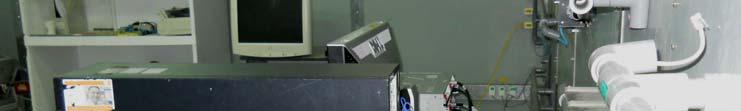
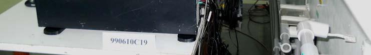
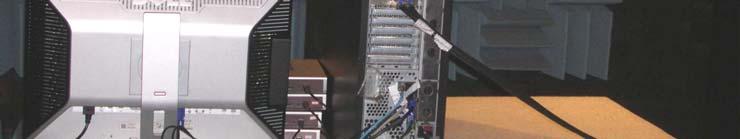
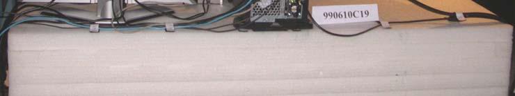
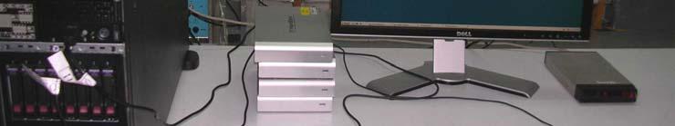
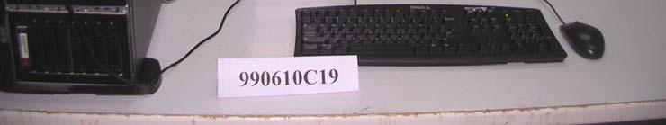
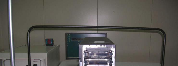
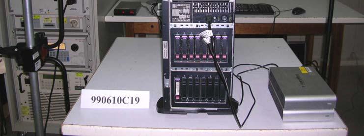
12 4. The client provided the following HDDs, which were installed into server for pre-test, and chosen the worst configuration for final test. HDD Brand Model No. Capacity Total SAS HDD Seagate ST SS 146GB 7 SAS HDD Seagate ST SS 146GB 1 SATA HDD Fujitsu MHW2060BK G2 60GB 8 5. The above EUT information was declared by manufacturer and for more detailed features description, please refer to the manufacturer's specifications or User's Manual THE PHOTO OF LOCATION OF EUT IN HOST Report No.: CE990610C19A 12 of 98 Report Format Version 5.0.1


13 3.1.2 THE PHOTO OF TOP AND BOTTOM SIDE OF EUT Model <Top Side> <Bottom Side> Report No.: CE990610C19A 13 of 98 Report Format Version 5.0.1


14 Model <Top Side> <Bottom Side> Report No.: CE990610C19A 14 of 98 Report Format Version 5.0.1

15 Model <Top Side> <Bottom Side> Report No.: CE990610C19A 15 of 98 Report Format Version 5.0.1

, Y5A2 (150MHz)> Report No.")
16 3.1.3 THE PHOTO OF NOISE SOURCES OF EUT Model <Y5L1 (133.33MHz), Y5L2 (150MHz)> Model <Y5A1 (133.33MHz), Y5A2 (150MHz)> Report No.: CE990610C19A 16 of 98 Report Format Version 5.0.1
, Y5L2 (150MHz)> Report No.")
17 Model <Y5L1 (133.33MHz), Y5L2 (150MHz)> Report No.: CE990610C19A 17 of 98 Report Format Version 5.0.1
18 3.1.4 THE CIRCUIT BLOCK DIAGRAM OF EUT Model Report No.: CE990610C19A 18 of 98 Report Format Version 5.0.1
19 Model Report No.: CE990610C19A 19 of 98 Report Format Version 5.0.1
20 Model Report No.: CE990610C19A 20 of 98 Report Format Version 5.0.1


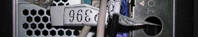
21 3.1.5 ID LABEL SPECIFICATION Model <Top Side> <Bottom Side> Report No.: CE990610C19A 21 of 98 Report Format Version 5.0.1


22 Model <Top Side> <Bottom Side> Report No.: CE990610C19A 22 of 98 Report Format Version 5.0.1

23 Model <Top Side> <Bottom Side> Report No.: CE990610C19A 23 of 98 Report Format Version 5.0.1
24 3.2 DESCRIPTION OF TEST MODES The EUT is designed for power from host with AC power supply of rating V, 50/60Hz. For radiated emission evaluation, 240Vac/50Hz (for AS/NZS CISPR 22), 230Vac/50Hz (for EN 55022), 120Vac/60Hz (for FCC Part 15), 110Vac/60Hz (for CNS 13438) and 100Vac/50Hz (for VCCI) had been covered during the pre-test. The worst radiated emission below 1GHz data was found at 230Vac/50Hz and recorded in the applied test report. The EUT was pre-tested under following modes, and test mode 3 was the worst case for final test. Test Mode Test Condition 1 EUT (25121) + SATA HDD (MHW2060BK G2) * 8 EUT (25121) + SAS HDD (ST SS) *7 + SAS HDD 2 (ST SS) *1 3 EUT (25152) + HDD storage (0834) *2 EUT (25305) + SATA HDD (MHW2060BK G2) * 4 + HDD storage 4 (0834) *1 Report No.: CE990610C19A 24 of 98 Report Format Version 5.0.1
25 3.3 GENERAL DESCRIPTION OF THE APPLIED STANDARD The EUT is a kind of ITE equipment, and according to the specifications of the manufacturers, must comply with the requirements of the following standards: EN 55022:2010 +AC:2011, Class B EN :2006 +A1:2009 +A2:2009, Class D EN :2008 EN 55024:2010 IEC :2008 ED. 2.0 / EN :2009 IEC :2010 ED. 3.2 / EN :2006 +A1:2008 +A2:2010 IEC :2012 ED.3.0 / EN :2004 +A1:2010 IEC :2005 ED. 2.0 / EN :2006 IEC :2008 ED. 3.0 / EN :2009 IEC :2009 ED. 2.0 / EN :2010 IEC :2004 ED. 2.0 / EN :2004 Note: The above IEC / EN basic standards are applied with latest version if customer has no special requirement. All tests have been performed and recorded as per the above standards. Report No.: CE990610C19A 25 of 98 Report Format Version 5.0.1
26 3.4 DESCRIPTION OF SUPPORT UNITS The EUT has been tested as an independent unit together with other necessary accessories or support units. The following support units or accessories were used to form a representative test configuration during the tests. For emission test NO. PRODUCT BRAND MODEL NO. SERIAL NO. FCC ID 1 SERVER HP HSTNS-2123 NA NA 2 HDD STORAGE *2 LSI 0834 NA NA 3 24" LCD MONITOR DELL 2408FPb CN-0G293H S-A00 FCC DoC Approved 4 MODEM ACEEX 1414V/ IFAXDM EXTERNAL HARD DISK EXTERNAL HARD DISK EXTERNAL HARD DISK EXTERNAL HARD DISK DELL DELL DELL DELL RD1000 RD1000 RD1000 RD KEYBOARD DELL SK-8110 HK-0XM Q-0005 CN-0F088R D-0009-A00 HK-0XM Q-001E CN-0F088R D-0005-A00 MY-05N B NA NA NA NA FCC DoC Approved 10 MOUSE DELL M071KC FCC DoC Approved 11 NOTEBOOK DELL PP18L D1T5W1S QDS-BRCM1019 NO. SIGNAL CABLE DESCRIPTION OF THE ABOVE SUPPORT UNITS Shielded / Length / Core Non-shielded Manufacturer Model Number or Part Number 1 NA NA NA NA 2 6 m mini SAS cable, w/o core Shielded MOLEX m VGA cable, with 2 cores Shielded NA NA m DB25 & DB9 cable, w/o core Shielded NA NA 5 2 m USB cable, with 2 cores Shielded NA NA 6 2 m USB cable, with 2 cores Shielded NA NA 7 2 m USB cable, with 2 cores Shielded NA NA 8 2 m USB cable, with 2 cores Shielded NA NA 9 2 m shielded PS/2 cable, w/o core Shielded NA NA 10 2 m shielded PS/2 cable, w/o core Shielded NA NA m RJ45 cable, w/o core Non-shielded NA NA Report No.: CE990610C19A 26 of 98 Report Format Version 5.0.1
27 NOTE: 1. AC power cord of the above support unit is non-shielded (1.8 m). 2. Item 11 act as a communication partner to link with server. 3. Item 1 and mini SAS cables were provided by the customer. For harmonic, flicker & immunity tests NO. PRODUCT BRAND MODEL NO. SERIAL NO. FCC ID 1 SERVER HP HSTNS-2123 NA NA 2 HDD STORAGE *2 LSI 0834 NA NA 3 24" LCD MONITOR DELL 2408FPb CN-0G293H S-A00 FCC DoC Approved 4 MODEM ACEEX 1414V/ IFAXDM EXTERNAL HARD DISK EXTERNAL HARD DISK EXTERNAL HARD DISK EXTERNAL HARD DISK Sarotech FHD-354US E80P NA Sarotech FHD-354UA E80L NA HARD BOX FHD-354US2 E80E NA SEAGATE FreeAgent XTreme 2GEROG04 NA 9 KEYBOARD DELL RT7D20 CN-04N BM-B213 AQ6-7D20 10 MOUSE DELL M071KC FCC DoC Approved 11 NOTEBOOK DELL D600 19LP91S QDS-BRCM1005-D NO. SIGNAL CABLE DESCRIPTION OF THE ABOVE SUPPORT UNITS Shielded / Length / Core Non-shielded Manufacturer Model Number or Part Number 1 NA NA NA NA 2 6 m mini SAS cable, w/o core Shielded MOLEX m VGA cable, with 2 cores Shielded NA NA m DB25 & DB9 cable, w/o core Shielded NA NA 5 2 m USB cable, w/o cores Shielded NA NA 6 2 m USB cable, w/o cores Shielded NA NA 7 2 m USB cable, w/o cores Shielded NA NA 8 2 m USB cable, w/o cores Shielded NA NA 9 2 m shielded PS/2 cable, w/o core Shielded NA NA 10 2 m shielded PS/2 cable, w/o core Shielded NA NA m RJ45 cable, w/o core Non-shielded NA NA Report No.: CE990610C19A 27 of 98 Report Format Version 5.0.1
28 NOTE: 1. AC power cord of the above support unit is non-shielded (1.8 m). 2. Item 11 act as a communication partner to link with server. 3. Item 1 and mini SAS cables were provided by the customer. 3.5 CONFIGURATION OF SYSTEM UNDER TEST Conducted emission test (Power from host equipment) HDD Storage *2 Modem Monitor EUT Server HDD *4 *Test Table Keyboard Mouse Notebook *Kept in a remote area Report No.: CE990610C19A 28 of 98 Report Format Version 5.0.1
29 Radiated emission test HDD Storage *2 (Power from host equipment) Modem EUT Server Monitor HDD *4 *Test Table Keyboard Mouse Notebook *Kept in a remote area Report No.: CE990610C19A 29 of 98 Report Format Version 5.0.1
30 For harmonic, flicker & immunity tests (Power from host equipment) Modem EUT Server Monitor HDD *4 *Test Table Keyboard Mouse Notebook HDD Storage *2 *Kept in a remote area Report No.: CE990610C19A 30 of 98 Report Format Version 5.0.1
31 4 EMISSION TEST 4.1 CONDUCTED EMISSION MEASUREMENT LIMITS OF CONDUCTED EMISSION MEASUREMENT TEST STANDARD: EN Frequency (MHz) Class A (dbuv) Class B (dbuv) Quasi-peak Average Quasi-peak Average NOTE: 1. The lower limit shall apply at the transition frequencies. 2. The limit decreases in line with the logarithm of the frequency in the range of 0.15 to 0.50 MHz. 3. All emanations from a class A/B digital device or system, including any network of conductors and apparatus connected thereto, shall not exceed the level of field strengths specified above TEST INSTRUMENTS DESCRIPTION & MANUFACTURER Test Receiver ROHDE & SCHWARZ RF signal cable Woken LISN SCHWARZBECK LISN ROHDE & SCHWARZ Software ADT MODEL NO. SERIAL NO. DATE OF CALIBRATION DUE DATE OF CALIBRATION ESCS Dec. 16, 2009 Dec. 15, D-FB Cable-HYC01-01 Nov. 12, 2009 Nov. 11, 2010 NNBL Jun. 12, 2010 Jun. 12, 2011 ESH3-Z /001 Feb., 10, 2010 Feb. 09, 2011 ADT_Cond_ V7.3.7 NA NA NA NOTE: 1. The calibration interval of the above test instruments is 12 months and the calibrations are traceable to NML/ROC and NIST/USA. 2. The test was performed in HwaYa Shielded Room The VCCI Site Registration No. is C Report No.: CE990610C19A 31 of 98 Report Format Version 5.0.1
32 4.1.3 TEST PROCEDURE a. The EUT was placed 0.4 meters from the conducting wall of the shielded room with EUT being connected to the power mains through a line impedance stabilization network (LISN). Other support units were connected to the power mains through another LISN. The two LISNs provide 50 Ohm/ 50uH of coupling impedance for the measuring instrument. b. Both lines of the power mains connected to the EUT were checked for maximum conducted interference. c. The frequency range from 150 khz to 30 MHz was searched. Emission levels under (Limit - 20dB) was not reported DEVIATION FROM TEST STANDARD No deviation. Report No.: CE990610C19A 32 of 98 Report Format Version 5.0.1
33 4.1.5 TEST SETUP V ertical Ground Reference Plane Test Receiver 40cm EUT LISN 80cm Horizontal Ground Reference Plane Note: 1.Support units were connected to second LISN. 2.Both of LISNs (AMN) are 80 cm from EUT and at least 80 cm from other units and other metal planes For the actual test configuration, please refer to the related item Photographs of the Test Configuration EUT OPERATING CONDITIONS a. The EUT was installed into server. b. The server ran test software (WinHpattern) to sent H patterns to LCD monitor, and LCD monitor displayed them. c. The server ran test software (WinHpattern) to exercise the EUT with providing data access as well as writing and reading data to external disk drives. d. The server ran test software (smasher.exe) to exercise the EUT with providing data access as well as writing and reading data to internal disk drives. e. The server sent messages to modem. f. Steps b~e were repeated. Report No.: CE990610C19A 33 of 98 Report Format Version 5.0.1
 Reading Value [db (uv)] Emission Level [db (uv)] Limit [db (uv)] Margin (db) Q.P. AV. Q.P. AV. Q.P. AV. Q.P. AV. 1 0.248 0.11 45.44-45.55-61.84 51.84-16.28-2 0.345 0.12 37.")
34 4.1.7 TEST RESULTS INPUT POWER (SYSTEM) 230 Vac, 50 Hz TESTED DATE Jun. 21, dB BANDWIDTH 9 khz PHASE Line 1 ENVIRONMENTAL CONDITIONS 20 deg. C, 65% RH, 981 hpa TESTED BY Eason Chen No Freq. [MHz] Corr. Factor (db) Reading Value [db (uv)] Emission Level [db (uv)] Limit [db (uv)] Margin (db) Q.P. AV. Q.P. AV. Q.P. AV. Q.P. AV REMARKS: 1. Q.P. and AV. are abbreviations of quasi-peak and average individually. 2. "-": The Quasi-peak reading value also meets average limit and measurement with the average detector is unnecessary. 3. The emission levels of other frequencies were very low against the limit. 4. Margin value = Emission level - Limit value 5. Correction factor = Insertion loss + Cable loss 6. Emission Level = Correction Factor + Reading Value. Report No.: CE990610C19A 34 of 98 Report Format Version 5.0.1
35 INPUT POWER (SYSTEM) 230 Vac, 50 Hz TESTED DATE Jun. 21, dB BANDWIDTH 9 khz PHASE Line 2 ENVIRONMENTAL CONDITIONS 20 deg. C, 65% RH, 981 hpa TESTED BY Eason Chen No Freq. [MHz] Corr. Factor (db) Reading Value [db (uv)] Emission Level [db (uv)] Limit [db (uv)] Margin (db) Q.P. AV. Q.P. AV. Q.P. AV. Q.P. AV REMARKS: 1. Q.P. and AV. are abbreviations of quasi-peak and average individually. 2. "-": The Quasi-peak reading value also meets average limit and measurement with the average detector is unnecessary. 3. The emission levels of other frequencies were very low against the limit. 4. Margin value = Emission level - Limit value 5. Correction factor = Insertion loss + Cable loss 6. Emission Level = Correction Factor + Reading Value. Report No.: CE990610C19A 35 of 98 Report Format Version 5.0.1

36 4.1.8 NOISE FLOOR MEASUREMENT Line 1 Line 2 Report No.: CE990610C19A 36 of 98 Report Format Version 5.0.1
37 4.2 RADIATED EMISSION MEASUREMENT LIMITS OF RADIATED EMISSION MEASUREMENT TEST STANDARD: EN Frequency (MHz) Class A (at 10m) Class B (at 10m) Quasi-peak (dbuv/m) Quasi-peak (dbuv/m) Frequency (MHz) Class A (at 3m) Class B (at 3m) Peak (dbuv/m) Average (dbuv/m) Peak (dbuv/m) Average (dbuv/m) NOTE: 1. The lower limit shall apply at the transition frequencies. 2. Emission level (dbuv/m) = 20 log Emission level (uv/m). 3. All emanations from a class A/B digital device or system, including any network of conductors and apparatus connected thereto, shall not exceed the level of field strengths specified above. FREQUENCY RANGE OF RADIATED MEASUREMENT Highest frequency generated or used within the EUT or on which the EUT operates or tunes (MHz) Upper frequency of measurement range (MHz) Below Above 1000 Up to 5 times of the highest frequency or 6 GHz, whichever is less Report No.: CE990610C19A 37 of 98 Report Format Version 5.0.1
38 4.2.2 TEST INSTRUMENTS Frequency range 30MHz ~ 1GHz DESCRIPTION & MANUFACTURER MODEL NO. SERIAL NO. DATE OF CALIBRATION DUE DATE OF CALIBRATION Test Receiver ROHDE & SCHWARZ Test Receiver ROHDE & SCHWARZ Spectrum Analyzer ROHDE & SCHWARZ BILOG Antenna SCHWARZBECK ESIB Dec. 11, 2009 Dec. 10, 2010 ESIB Sep. 18, 2009 Sep. 17, 2010 FSP Dec. 31, 2009 Dec. 30, 2010 VULB Apr. 27, 2010 Apr. 26, 2011 BILOG Antenna SCHWARZBECK HORN Antenna EMCO Preamplifier Agilent Preamplifier Agilent Preamplifier Agilent RF signal cable Woken RF signal cable Woken Software ADT VULB Apr. 27, 2010 Apr. 26, Jul. 29, 2009 Jul. 28, D 2944A10636 Dec. 10, 2009 Dec. 09, D 2944A10637 Dec. 10, 2009 Dec. 09, B 3008A01959 Dec. 10, 2009 Dec. 09, D-FB Cable-Hych1-01 Oct. 24, 2009 Oct. 23, D-FB Cable-Hych1-02 Oct. 24, 2009 Oct. 23, 2010 ADT_Radiated_ V NA NA NA Antenna Tower(V) MFA NA NA Antenna Tower(H) MFA NA NA Turn Table DS NA NA Controller MF NA NA Controller MF NA NA RF signal cable EAST COST Microwave HP 160S-29 NA Feb. 12, 2010 Feb. 11, 2011 NOTE: 1. The calibration interval of the above test instruments is 12 months and the calibrations are traceable to NML/ROC and NIST/USA. 2. The test was performed in HwaYa Chamber The FCC Site Registration No. is The IC Site Registration No. is IC 7450F The VCCI Site Registration No. is R Report No.: CE990610C19A 38 of 98 Report Format Version 5.0.1
39 Frequency range above 1GHz DESCRIPTION & MANUFACTURER Test Receiver ROHDE & SCHWARZ Spectrum Analyzer ROHDE & SCHWARZ BILOG Antenna SCHWARZBECK HORN Antenna SCHWARZBECK HORN Antenna SCHWARZBECK Preamplifier Agilent Preamplifier Agilent RF signal cable HUBER+SUHNER RF signal cable HUBER+SUHNER Software ADT. Antenna Tower ADT. Turn Table ADT. Controller ADT. MODEL NO. SERIAL NO. DATE OF CALIBRATION DUE DATE OF CALIBRATION ESIB Dec. 21, 2009 Dec. 20, 2010 FSP Jan. 11, 2010 Jan. 10, 2011 VULB Apr. 29, 2010 Apr. 28, 2011 BBHA 9120 D 9120D-405 Feb. 03, 2010 Feb. 02, 2011 BBHA 9170 BBHA Jul. 06, 2009 Jul. 05, D 2944A10629 Nov. 04, 2009 Nov. 03, B 3008A01959 Dec. 10, 2009 Dec. 09, 2010 SUCOFLEX /6 Aug. 28, 2009 Aug. 27, 2010 SUCOFLEX /4 Aug. 28, 2009 Aug. 27, 2010 ADT_Radiated_ V NA NA NA AT100 AT NA NA TT100. TT NA NA SC100. SC NA NA NOTE: 1. The calibration interval of the above test instruments is 12 months and the calibrations are traceable to NML/ROC and NIST/USA. 2. The test was performed in HwaYa Chamber The horn antenna and HP preamplifier (model: 8449B) are used only for the measurement of emission frequency above 1GHz if tested. 4. The FCC Site Registration No. is The IC Site Registration No. is IC 7450F The VCCI Site Registration No. is G-18. Report No.: CE990610C19A 39 of 98 Report Format Version 5.0.1
40 4.2.3 TEST PROCEDURE Frequency range 30MHz ~ 1GHz a. The EUT was placed on the top of a rotating table 0.8 meters above the ground at a 10 meter semi-anechoic chamber room. The table was rotated 360 degrees to determine the position of the highest radiation. b. The EUT was set 10 meters away from the interference-receiving antenna, which was mounted on the top of a variable-height antenna tower. c. The height of antenna is varied from 1 meter to 4 meters above the ground to determine the maximum value of the field strength. Both horizontal and vertical polarizations of the antenna are set to make the measurement. d. For each suspected emission, the EUT was arranged to its worst case and then the antenna was tuned to heights from 1 meter to 4 meters and the rotatable table was turned from 0 degrees to 360 degrees to find the maximum reading. e. The test-receiver system was set to quasi-peak detect function and specified bandwidth with maximum hold mode when the test frequency is below 1 GHz. NOTE: The resolution bandwidth of test receiver/spectrum analyzer is 120 khz for Quasi-Peak (QP) detection at frequency below 1 GHz. Report No.: CE990610C19A 40 of 98 Report Format Version 5.0.1
41 Frequency range above 1GHz a. The EUT was placed on the top of a rotating table 0.8 meters above the ground at a 3 meter semi-anechoic chamber room. The table was rotated 360 degrees to determine the position of the highest radiation. b. The EUT was set 3 meters away from the interference-receiving antenna, which was mounted on the top of a variable-height antenna tower. c. The height of antenna can be varied from 1 meter to 4 meters, the height of adjustment depends on the EUT height and the antenna 3dB beamwidth both, to detect the maximum value of the field strength. Both horizontal and vertical polarizations of the antenna are set to make the measurement. d. For each suspected emission, the EUT was arranged to its worst case and then the antenna was tuned to heights and the rotatable table was turned from 0 degrees to 360 degrees to find the maximum reading. e. The test-receiver system was set to peak and average detect function and specified bandwidth with maximum hold mode when the test frequency is above 1 GHz. NOTE: 1. The resolution bandwidth is 1MHz and video bandwidth of test receiver/spectrum analyzer is 3 MHz for Peak (PK) detection at frequency above 1 GHz. The resolution bandwidth of test receiver/spectrum analyzer is 1 MHz for Average (AV) detection at frequency above 1 GHz. 2. For measurement of frequency above 1000 MHz, the EUT was set 3 meters away from the receiver antenna DEVIATION FROM TEST STANDARD No deviation. Report No.: CE990610C19A 41 of 98 Report Format Version 5.0.1

42 4.2.5 TEST SETUP Frequency range 30MHz ~ 1GHz Frequency range above 1GHz EUT& Support Units 3m Ant. Tower 1-4m* Variable Turn Table Absorber 80cm Ground Plane Spectrum analyzer * : depends on the EUT height and the antenna 3dB beamwidth both, refer to section 7.3 of CISPR For the actual test configuration, please refer to the related Item Photographs of the Test Configuration EUT OPERATING CONDITIONS Same as Report No.: CE990610C19A 42 of 98 Report Format Version 5.0.1
43 4.2.7 TEST RESULTS INPUT POWER (SYSTEM) FREQUENCY RANGE ENVIRONMENTAL CONDITIONS 230 Vac, 50 Hz TESTED DATE Jun. 20, MHz 22 deg. C, 65% RH, 981 hpa DETECTOR FUNCTION & BANDWIDTH TESTED BY Quasi-Peak, 120 khz Eason Chen No. Freq. (MHz) ANTENNA POLARITY & TEST DISTANCE: HORIZONTAL AT 10 M Emission Level (dbuv/m) Limit (dbuv/m) Margin (db) Antenna Height (m) Table Angle (Degree) Raw Value (dbuv) Correction Factor (db/m) QP H QP H QP H QP H QP H QP H QP H REMARKS: 1. Emission level(dbuv/m)=raw Value(dBuV) + Correction Factor(dB/m) 2. Correction Factor(dB/m) = Antenna Factor (db/m) + Cable Factor (db) 3. The other emission levels were very low against the limit. 4. Margin value = Emission level Limit value. Report No.: CE990610C19A 43 of 98 Report Format Version 5.0.1

44 INPUT POWER (SYSTEM) FREQUENCY RANGE ENVIRONMENTAL CONDITIONS 230 Vac, 50 Hz TESTED DATE Jun. 20, MHz 22 deg. C, 65% RH, 981 hpa DETECTOR FUNCTION & BANDWIDTH TESTED BY Quasi-Peak, 120 khz Eason Chen No. Freq. (MHz) ANTENNA POLARITY & TEST DISTANCE: VERTICAL AT 10 M Emission Level (dbuv/m) Limit (dbuv/m) Margin (db) Antenna Height (m) Table Angle (Degree) Raw Value (dbuv) Correction Factor (db/m) QP V QP V QP V QP V QP V QP V REMARKS: 1. Emission level(dbuv/m)=raw Value(dBuV) + Correction Factor(dB/m) 2. Correction Factor(dB/m) = Antenna Factor (db/m) + Cable Factor (db) 3. The other emission levels were very low against the limit. 4. Margin value = Emission level Limit value. Report No.: CE990610C19A 44 of 98 Report Format Version 5.0.1
45 INPUT POWER (SYSTEM) FREQUENCY RANGE ENVIRONMENTAL CONDITIONS 230 Vac, 50 Hz TESTED DATE Jun. 18, GHz 25 deg. C, 67% RH, 981 hpa DETECTOR FUNCTION & BANDWIDTH TESTED BY Peak/Average, 1 MHz Whisky Chang No. Freq. (MHz) ANTENNA POLARITY & TEST DISTANCE: HORIZONTAL AT 3 M Emission Level (dbuv/m) Limit (dbuv/m) Margin (db) Antenna Height (m) Table Angle (Degree) Raw Value (dbuv) Correction Factor (db/m) PK H AV H PK H AV H PK H AV H REMARKS: 1. Emission level(dbuv/m)=raw Value(dBuV) + Correction Factor(dB/m) 2. Correction Factor(dB/m) = Antenna Factor (db/m) + Cable Factor (db) 3. The other emission levels were very low against the limit. 4. Margin value = Emission level Limit value. Report No.: CE990610C19A 45 of 98 Report Format Version 5.0.1

46 INPUT POWER (SYSTEM) FREQUENCY RANGE ENVIRONMENTAL CONDITIONS 230 Vac, 50 Hz TESTED DATE Jun. 18, GHz 25 deg. C, 67% RH, 981 hpa DETECTOR FUNCTION & BANDWIDTH TESTED BY Peak/Average, 1 MHz Whisky Chang No. Freq. (MHz) ANTENNA POLARITY & TEST DISTANCE: VERTICAL AT 3 M Emission Level (dbuv/m) Limit (dbuv/m) Margin (db) Antenna Height (m) Table Angle (Degree) Raw Value (dbuv) Correction Factor (db/m) PK V AV V PK V AV V PK V AV V REMARKS: 1. Emission level(dbuv/m)=raw Value(dBuV) + Correction Factor(dB/m) 2. Correction Factor(dB/m) = Antenna Factor (db/m) + Cable Factor (db) 3. The other emission levels were very low against the limit. 4. Margin value = Emission level Limit value. Report No.: CE990610C19A 46 of 98 Report Format Version 5.0.1
47 4.2.8 NOISE FLOOR MEASUREMENT Frequency range 30MHz ~ 1GHz Horizontal Vertical Report No.: CE990610C19A 47 of 98 Report Format Version 5.0.1
48 Frequency range above 1GHz Horizontal Vertical Report No.: CE990610C19A 48 of 98 Report Format Version 5.0.1
49 4.3 HARMONICS CURRENT MEASUREMENT LIMITS OF HARMONICS CURRENT MEASUREMENT TEST STANDARD: EN Limits for Class A equipment Harmonics Order n Max. permissible harmonics current A Harmonics Order n Limits for Class D equipment Max. permissible harmonics current per watt ma/w Odd Harmonics only Odd harmonics <=n<= x15/n 15<=n<= /n 0.15x15/n Even harmonics <=n<= x8/n Max. permissible harmonics current A NOTE: 1. Class A and Class D are classified according to item section 5 of EN According to section 7 of EN , the above limits for all equipment except for lighting equipment having an active input power > 75 W and no limits apply for equipment with an active input power up to and including 75 W. Report No.: CE990610C19A 49 of 98 Report Format Version 5.0.1
50 4.3.2 TEST INSTRUMENTS DESCRIPTION & MANUFACTURER MODEL NO. SERIAL NO. DATE OF CALIBRATION DUE DATE OF CALIBRATION Schaffner AC Power Source NSG Nov. 12, 2009 Nov. 11, 2010 Schaffner Signal Conditioning Unit- Lumped Impedance Software CCN LR Nov. 12, 2009 Nov. 11, 2010 Schaffner Win 2100V3 NOTE: 1. The test was performed in Hwa Ya EMS Room. NA NA NA 2. The calibration interval of the above test instruments is 12 months and the calibrations are traceable to NML/ROC and NIST/USA TEST PROCEDURE a. The EUT was placed on the top of a wooden table 0.8 meters above the ground and operated to produce the maximum harmonic components under normal operating conditions for each successive harmonic component in turn. b. The classification of EUT is according to section 5 of EN The EUT is classified as follows: Class A: Balanced three-phase equipment, Household appliances excluding equipment as Class D, Tools excluding portable tools, Dimmers for incandescent lamps, audio equipment, equipment not specified in one of the three other classes. Class B: Portable tools. Arc welding equipment which is not professional equipment. Class C: Lighting equipment. Class D: Equipment having a specified power less than or equal to 600 W of the following types: Personal computers, personal computer monitors and TV receivers. c. The correspondent test program of test instrument to measure the current harmonics emanated from EUT is chosen. The measure time shall be not less than the time necessary for the EUT to be exercised DEVIATION FROM TEST STANDARD No deviation. Report No.: CE990610C19A 50 of 98 Report Format Version 5.0.1
51 4.3.5 TEST SETUP EUT For the actual test configuration, please refer to the related item Photographs of the Test Configuration EUT OPERATING CONDITIONS a. The EUT was installed into server. b. The server ran test software (WinHpattern) to sent H patterns to LCD monitor, and LCD monitor displayed them. c. The server ran test software (WinHpattern) to exercise the EUT with providing data access as well as writing and reading data to external disk drives. d. The server ran test software (smasher.exe) to exercise the EUT with providing data access as well as writing and reading data to internal disk drives. e. The server sent messages to modem. f. Steps b~e were repeated. Report No.: CE990610C19A 51 of 98 Report Format Version 5.0.1
52 4.3.7 TEST RESULTS FUNDAMENTAL VOLTAGE/AMPERE RATED POWER CONSUMPTION ENVIRONMENTAL CONDITIONS Vrms Amps W 24 deg. C, 51% RH, 981 hpa TEST DATE Jun. 24, 2010 POWER FREQUENCY POWER FACTOR Hz TEST DURATION 3 min. TESTED BY JN Chen Current RMS(Amps) Harmonic # Report No.: CE990610C19A 52 of 98 Report Format Version 5.0.1
53 Harm # Harms (avg) 100% Limit Harms (max) 150% Limit (A) (A) (A) (A) Test Result PASS PASS PASS PASS PASS PASS PASS PASS PASS PASS PASS PASS PASS PASS PASS PASS PASS PASS PASS NOTE: Dynamic limits were applied for this test. The highest harmonics values in the above table may not occur at the same window as the maximum harmonics/limit ratio. Report No.: CE990610C19A 53 of 98 Report Format Version 5.0.1
54 4.4 VOLTAGE FLUCTUATION AND FLICKS MEASUREMENT LIMITS OF VOLTAGE FLUCTUATION AND FLICKS MEASUREMENT TEST STANDARD: EN Test Item Limit Note Pst 1.0 Pst means short-term flicker indicator. Plt 0.65 Plt means long-term flicker indicator. Tdt (ms) 500 Tdt means maximum time that dt exceeds 3.3 %. dmax (%) 4% dmax means maximum relative voltage change. dc (%) 3.3% dc means relative steady-state voltage change TEST INSTRUMENTS DESCRIPTION & MANUFACTURER MODEL NO. SERIAL NO. DATE OF CALIBRATION DUE DATE OF CALIBRATION Schaffner AC Power Source NSG Nov. 12, 2009 Nov. 11, 2010 Schaffner Signal Conditioning Unit- Lumped Impedance Software CCN LR Nov. 12, 2009 Nov. 11, 2010 Schaffner Win 2100V3 NOTE: 1. The test was performed in Hwa Ya EMS Room. NA NA NA 2. The calibration interval of the above test instruments is 12 months and the calibrations are traceable to NML/ROC and NIST/USA TEST PROCEDURE a. The EUT was placed on the top of a wooden table 0.8 meters above the ground and operated to produce the most unfavorable sequence of voltage changes under normal operating conditions. b. During the flick measurement, the measure time shall include that part of whole operation cycle in which the EUT produce the most unfavorable sequence of voltage changes. The observation period for short-term flicker indicator is 10 minutes and the observation period for long-term flicker indicator is 2 hours. Report No.: CE990610C19A 54 of 98 Report Format Version 5.0.1
55 4.4.4 DEVIATION FROM TEST STANDARD The requirement is according to client s specification TEST SETUP EUT For the actual test configuration, please refer to the related item Photographs of the Test Configuration EUT OPERATING CONDITIONS Same as Report No.: CE990610C19A 55 of 98 Report Format Version 5.0.1
56 4.4.7 TEST RESULTS FUNDAMENTAL VOLTAGE/AMPERE ENVIRONMENTAL CONDITIONS OBSERVATION PERIOD (Tp) TESTED BY Vrms Amps 24 deg. C, 51% RH, 981 hpa TEST DATE Jun. 24, 2010 POWER FREQUENCY Hz 120 min. POWER FACTOR JN Chen Test Parameter Measurement Value Limit Remark P st PASS P lt PASS T dt (ms) PASS d max (%) % PASS dc (%) 0 3.3% PASS NOTE: 1. P st means short-term flicker indicator. 2. P lt means long-term flicker indicator. 3. T dt means maximum time that dt exceeds 3.3 %. 4. d max means maximum relative voltage change. 5. dc means relative steady-state voltage change. Report No.: CE990610C19A 56 of 98 Report Format Version 5.0.1
57 5 IMMUNITY TEST 5.1 GENERAL DESCRIPTION Product Standard EN EN Basic Standard, specification requirement, and Performance Criteria EN EN EN EN EN EN Electrostatic Discharge ESD: 8 kv air discharge, 4 kv contact discharge, Performance Criterion B Radio-Frequency Electromagnetic Field Susceptibility Test RS: MHz, 3 V/m, 80% AM (1 khz), Performance Criterion A Electrical Fast Transient/Burst - EFT AC power line: 1 kv, DC power line: 0.5 kv, Signal line: 0.5 kv Performance Criterion B Surge Immunity Test: 1.2/50 us Open Circuit Voltage, 8/20 us Short Circuit Current AC power line: line to line 1 kv, line to earth 2 kv, DC power line: line to earth 0.5 kv, Signal line: 1 kv Performance Criterion B Conducted Radio Frequency Disturbances Test CS: MHz, 3 Vrms, 80% AM, 1 khz, Performance Criterion A Power Frequency Magnetic Field Test, 50 Hz, 1 A/m, Performance Criterion A Voltage Dips: i) >95% reduction -0.5 period, Performance Criterion B ii) 30% reduction 25 period, Performance Criterion C Voltage Interruptions: i) >95% reduction 250 period, Performance Criterion C Report No.: CE990610C19A 57 of 98 Report Format Version 5.0.1
58 5.2 GENERAL PERFORMANCE CRITERIA DESCRIPTION According to Clause 7.1 of EN standard, the following describes the general performance criteria. Criterion A Criterion B Criterion C The equipment shall continue to operate as intended without operator intervention. No degradation of performance or loss of function is allowed below a performance level specified by the manufacturer when the equipment is used as intended. The performance level may be replaced by a permissible loss of performance. If the minimum performance level or the permissible performance loss is not specified by the manufacturer, then either of these may be derived from the product description and documentation, and by what the user may reasonably expect from the equipment if used as intended. After the test, the equipment shall continue to operate as intended without operator intervention. No degradation of performance or loss of function is allowed, after the application of the phenomenon below a performance level specified by the manufacturer, when the equipment is used as intended. The performance level may be replaced by a permissible loss of performance. During the test, degradation of performance is allowed. However, no change of operating state if stored data is allowed to persist after the test. If the minimum performance level (or the permissible performance loss) is not specified by the manufacturer, then either of these may be derived from the product description and documentation, and by what the user may reasonably expect from the equipment if used as intended. Loss of function is allowed, provided the function is self-recoverable, or can be restored by the operation of the controls by the user in accordance with the manufacturer s instructions. Functions, and/or information stored in non-volatile memory, or protected by a battery backup, shall not be lost. Report No.: CE990610C19A 58 of 98 Report Format Version 5.0.1
59 5.3 PARTICULAR PERFORMANCE CRITERIA DESCRIPTION FOR LAN FUNCTION OF EUT Criterion A Criterion B Criterion C During and after the test, the EUT shall operate without: - error rate beyond the figure defined by the manufacturer; - requests for retry beyond the figure defined by the manufacturer; - speed of data transmission rate beyond the figure defined by the manufacturer; - protocol failure; - loss of link Error rate, request for retry and speed of data transmission rate may be degraded during the application of the test. Degradation of the performance as described in criteria A is permitted provided that the normal operation of the EUT is self-recoverable to the condition immediately before the application of the test. In these cases, operator response is permitted to re-initiate an operation. Degradation of the performance as described in criteria A and B is permitted provided that the normal operation of the EUT is self-recoverable to the condition immediately before the application of the test or can be restored after the test by the operator. 5.4 EUT OPERATING CONDITION Same as Report No.: CE990610C19A 59 of 98 Report Format Version 5.0.1
60 5.5 ELECTROSTATIC DISCHARGE IMMUNITY TEST (ESD) TEST SPECIFICATION Basic Standard: EN Discharge Impedance: 330 ohm / 150 pf Discharge Voltage: Air Discharge: 2, 4, 8 kv (Direct) Contact Discharge: 2, 4, 6 kv (Direct / Indirect) Polarity: Positive & Negative Number of Discharge: Air Discharge: min. 20 times at each test point Contact Discharge: min. 50 times at each test point Discharge Mode: Single Discharge Discharge Period: 1 second minimum TEST INSTRUMENTS DESCRIPTION & MANUFACTURER Electronic Discharge Simulator (KeyTek) MODEL NO. SERIAL NO. DATE OF CALIBRATION DUE DATE OF CALIBRATION MZ-151EC May 26, 2010 May 25, 2011 NOTE: 1. The test was performed in Hwa Ya ESD Room No The calibration interval of the above test instruments is 12 months and the calibrations are traceable to NML/ROC and NIST/USA. Report No.: CE990610C19A 60 of 98 Report Format Version 5.0.1
61 5.5.3 TEST PROCEDURE The discharges shall be applied in two ways: a. Contact discharges to the conductive surfaces and coupling planes: The EUT shall be exposed to at least 200 discharges, 100 each at negative and positive polarity, at a minimum of four test points. One of the test points shall be subjected to at least 50 indirect discharges to the center of the front edge of the horizontal coupling plane. The remaining three test points shall each receive at least 50 direct contact discharges. If no direct contact test points are available, then at least 200 indirect discharges shall be applied in the indirect mode. Test shall be performed at a maximum repetition rate of one discharge per second. b. Air discharges at slots and apertures and insulating surfaces: On those parts of the EUT where it is not possible to perform contact discharge testing, the equipment should be investigated to identify user accessible points where breakdown may occur. Such points are tested using the air discharge method. This investigation should be restricted to those area normally handled by the user. A minimum of 10 single air discharges shall be applied to the selected test point for each such area. The basic test procedure was in accordance with EN : a. Electrostatic discharges were applied only to those points and surfaces of the EUT that are accessible to users during normal operation. b. The test was performed with at least ten single discharges on the pre-selected points in the most sensitive polarity. c. The time interval between two successive single discharges was at least 1 second. d. The ESD generator was held perpendicularly to the surface to which the discharge was applied and the return cable was at least 0.2 meters from the EUT. e. Contact discharges were applied to the non-insulating coating, with the pointed tip of the generator penetrating the coating and contacting the conducting substrate. f. Air discharges were applied with the round discharge tip of the discharge electrode approaching the EUT as fast as possible (without causing mechanical damage) to touch the EUT. After each discharge, the ESD generator was removed from the EUT and re-triggered for a new single discharge. The test was repeated until all discharges were complete. g. At least ten single discharges (in the most sensitive polarity) were applied to the Horizontal Coupling Plane at points on each side of the EUT. The ESD generator was positioned horizontally at a distance of 0.1 meters from the EUT with the discharge electrode touching the HCP. h. At least ten single discharges (in the most sensitive polarity) were applied to the center of one vertical edge of the Vertical Coupling Plane in sufficiently different positions that the four faces of the EUT were completely illuminated. The VCP (dimensions 0.5m x 0.5m) was placed vertically to and 0.1 meters from the EUT. Report No.: CE990610C19A 61 of 98 Report Format Version 5.0.1
62 5.5.4 DEVIATION FROM TEST STANDARD The requirement is according to client s specification TEST SETUP For the actual test configuration, please refer to the related item Photographs of the Test Configuration. NOTE: TABLE-TOP EQUIPMENT The configuration consisted of a wooden table 0.8 meters high standing on the Ground Reference Plane. The GRP consisted of a sheet of aluminum at least 0.25mm thick, and 2.5 meters square connected to the protective grounding system. A Horizontal Coupling Plane (1.6m x 0.8m) was placed on the table and attached to the GRP by means of a cable with 940kΩ total impedance. The equipment under test, was installed in a representative system as described in section 7 of EN , and its cables were placed on the HCP and isolated by an insulating support of 0.5mm thickness. A distance of 1-meter minimum was provided between the EUT and the walls of the laboratory and any other metallic structure. FLOOR-STANDING EQUIPMENT The equipment under test was installed in a representative system as described in section 7 of EN , and its cables were isolated from the Ground Reference Plane by an insulating support of 0.1-meter thickness. The GRP consisted of a sheet of aluminum that is at least 0.25mm thick, and 2.5 meters square connected to the protective grounding system and extended at least 0.5 meters from the EUT on all sides. Report No.: CE990610C19A 62 of 98 Report Format Version 5.0.1
63 5.5.6 TEST RESULTS INPUT POWER (SYSTEM) ENVIRONMENTAL CONDITIONS 230 Vac, 50 Hz TEST DATE Apr. 22, deg. C, 53% RH 1012 hpa TESTED BY Dark Su Discharge Level (kv) Polarity TEST RESULTS OF DIRECT APPLICATION Test Point Contact Discharge Air Discharge Performance Criterion 2, 4, 6 +/- 1-4 NOTE NA A 2, 4, 8 +/- 5-7 NA NOTE A Description of test point: Please refer to following photos for representative mark only. Discharge Level (kv) Polarity TEST RESULTS OF INDIRECT APPLICATION Test Point Horizontal Coupling Plane Vertical Coupling Plane Performance Criterion 2, 4, 6 +/- 4 sides NOTE NOTE A Description of test point: 1. Front side 2. Rear side 3. Right side 4. Left side NOTE: There was no change compared with initial operation during and after the test. Report No.: CE990610C19A 63 of 98 Report Format Version 5.0.1


64 1 Report No.: CE990610C19A 64 of 98 Report Format Version 5.0.1


65 2 7 3 Report No.: CE990610C19A 65 of 98 Report Format Version 5.0.1


66 4 5 Report No.: CE990610C19A 66 of 98 Report Format Version 5.0.1


67 Report No.: CE990610C19A 67 of 98 Report Format Version
68 5.6 RADIATED, RADIO-FREQUENCY, ELECTROMAGNETIC FIELD IMMNITY TEST (RS) TEST SPECIFICATION Basic Standard: EN Frequency Range: 80 MHz ~ 1000 MHz, 100 MHz, MHz, 150 MHz, 300 MHz, 533 MHz, 800 MHz Field Strength: 3 V/m Modulation: 1 khz Sine Wave, 80%, AM Modulation Frequency Step: 1 % of preceding frequency value Polarity of Antenna: Horizontal and Vertical Antenna Height: 1.5 m Dwell Time: 3, 60 seconds TEST INSTRUMENTS DESCRIPTION & MANUFACTURER MODEL NO. SERIAL NO. DATE OF CALIBRATION DUE DATE OF CALIBRATION Boonton RF Power Meter 4232A Apr. 22, 2010 Apr. 21, 2011 R&S Signal Generator SML Aug. 31, 2009 Aug. 30, 2010 LOG ANTENNA AT5080ANT NA NA Amplifier 60S1G3M NA NA Amplifier RF TEST SYSCTRLR SC1000M NA NA Amplifier 150W NA NA Amplifier DC7144A NA NA POWER SENSOR EMC Apr. 22, 2010 Apr. 21, 2011 POWER SENSOR EMC Apr. 22, 2010 Apr. 21, 2011 Software ADT_RS_V450 NA NA NA NOTE: 1. The test was performed in Hwa Ya RS Room The calibration interval of the above test instruments is 12 months and the calibrations are traceable to NML/ROC and NIST/USA. 3. The transmit antenna was located at a distance of 2.0 meters from the EUT. (For frequency range 80MHz ~ 1GHz). Report No.: CE990610C19A 68 of 98 Report Format Version 5.0.1
69 5.6.3 TEST PROCEDURE The test procedure was in accordance with EN a. The testing was performed in a fully-anechoic chamber. b. The frequency range is swept from 80 MHz to 1000 MHz, 100 MHz, MHz, 150 MHz, 300 MHz, 533 MHz, 800 MHz, with the signal 80% amplitude modulated with a 1 khz sinewave. c. The dwell time at each frequency shall not be less than the time necessary for the EUT to be exercised and to respond, but shall in no case be less than 0.5s. d. The field strength level was 3 V/m. e. The test was performed with the EUT exposed to both vertically and horizontally polarized fields on each of the four sides DEVIATION FROM TEST STANDARD The requirement is according to client s specification. Report No.: CE990610C19A 69 of 98 Report Format Version 5.0.1
70 5.6.5 TEST SETUP EUT RF Amplifier RF Generator and control system Monitoring system For the actual test configuration, please refer to the related item Photographs of the Test Configuration. NOTE: TABLETOP EQUIPMENT The EUT installed in a representative system as described in section 7 of EN was placed on a non-conductive table 0.8 meters in height. The system under test was connected to the power and signal wire according to relevant installation instructions. FLOOR STANDING EQUIPMENT The EUT installed in a representative system as described in section 7 of EN was placed on a non-conductive wood support 0.1 meters in height. The system under test was connected to the power and signal wire according to relevant installation instructions. Report No.: CE990610C19A 70 of 98 Report Format Version 5.0.1
71 5.6.6 TEST RESULTS INPUT POWER (SYSTEM) ENVIRONMENTAL CONDITIONS 230 Vac, 50 Hz TEST DATE Jun. 23, deg. C, 56% RH 1014 hpa TESTED BY Andy Chang Frequency (MHz) Polarity Azimuth Field Strength (V/m) Dwell Time (sec.) Observation Performance Criterion V&H 0, 90, 180, NOTE A 100 V&H 0, 90, 180, NOTE A V&H 0, 90, 180, NOTE A 150 V&H 0, 90, 180, NOTE A 300 V&H 0, 90, 180, NOTE A 533 V&H 0, 90, 180, NOTE A 800 V&H 0, 90, 180, NOTE A NOTE: There was no change compared with initial operation during and after the test. Report No.: CE990610C19A 71 of 98 Report Format Version 5.0.1
72 5.7 ELECTRICAL FAST TRANSIENT/BURST IMMUNITY TEST (EFT) TEST SPECIFICATION Basic Standard: EN Test Voltage: Power line: 1 kv Signal line: 0.5 kv Polarity: Positive & Negative Impulse Frequency: 5 khz Impulse Waveshape: 5/50 ns Burst Duration: 15 ms Burst Period: 300 ms Test Duration: 1 min TEST INSTRUMENTS DESCRIPTION & MANUFACTURER EMC-Partner EFT Generator EMC-Partner Capacitive Coupling clamp MODEL NO. SERIAL NO. DATE OF CALIBRATION DUE DATE OF CALIBRATION TRA2000EFT-C1 623 Sep. 10, 2009 Sep. 09, 2010 CN-EFT NA NA EFT Adapter WONPRO WA EF1Ada-001 NA NA Software EMC-Partner GENECS NA NA NA NOTE: 1. The test was performed in Hwa Ya EFT Room. 2. The calibration interval of the above test instruments is 12 months and the calibrations are traceable to NML/ROC and NIST/USA TEST PROCEDURE a. Both positive and negative polarity discharges were applied. b. The length of the hot wire from the coaxial output of the EFT generator to the terminals on the EUT was 0.5 m. c. The duration time of each test sequential was 1 minute. d. The transient/burst waveform was in accordance with EN , 5/50ns. Report No.: CE990610C19A 72 of 98 Report Format Version 5.0.1
73 5.7.4 DEVIATION FROM TEST STANDARD No deviation TEST SETUP NOTE: / length between clamp and the EUT to be tested (should be 0.5 m ± 0.05 m) (A) location for supply line coupling (B) location for signal lines coupling For the actual test configuration, please refer to the related item Photographs of the Test Configuration. NOTE: EUTs, whether stationary floor-mounted or table top, and equipment designed to be mounted in other configurations, shall be placed on a ground reference plane and shall be insulated from it by an insulating support 0.1 m ± 0.01 m thick. A minimum distance of 0.5m was provided between the EUT and the walls of the laboratory or any other metallic structure. Report No.: CE990610C19A 73 of 98 Report Format Version 5.0.1
74 5.7.6 TEST RESULTS INPUT POWER (SYSTEM) ENVIRONMENTAL CONDITIONS 230 Vac, 50 Hz TEST DATE Jun. 23, deg. C, 56% RH 1014 hpa TESTED BY Brian Hsieh Test Point Polarity Test Level (kv) Observation Performance Criterion L1 +/- 1 NOTE A L2 +/- 1 NOTE A PE +/- 1 NOTE A L1-L2-PE +/- 1 NOTE A Mini SAS cable +/- 0.5 NOTE A NOTE: There was no change compared with initial operation during and after the test. Report No.: CE990610C19A 74 of 98 Report Format Version 5.0.1
75 5.8 SURGE IMMUNITY TEST TEST SPECIFICATION Basic Standard: EN Wave-Shape: Combination Wave 1.2/50 us Open Circuit Voltage 8 /20 us Short Circuit Current Test Voltage: Power port: 0.5, 1, 2 kv Surge Input/Output: L1-L2, L1-PE, L2-PE Generator Source Impedance: 2 ohm between networks 12 ohm between network and ground Polarity: Positive/Negative Phase Angle: 0 /90 /180 /270 Pulse Repetition Rate: 60 sec. Number of Tests: 5 positive and 5 negative at selected points TEST INSTRUMENTS DESCRIPTION & MANUFACTURER Modular Impulse Generator EMC-Partner Modular MODEL NO. SERIAL NO. DATE OF CALIBRATION DUE DATE OF CALIBRATION MIG0603IN3 352 Aug. 28, 2009 Aug. 27, 2010 EMC-Partner CDN UTP8 011 Aug. 28, 2009 Aug. 27, 2010 Surge Adapter WONPRO WA SU1 Ada-001 NA NA NOTE: 1. The test was performed in Hwa Ya Surge Room. 2. The calibration interval of the above test instruments is 12 months and the calibrations are traceable to NML/ROC and NIST/USA. Report No.: CE990610C19A 75 of 98 Report Format Version 5.0.1
76 5.8.3 TEST PROCEDURE a. For EUT power supply: The surge is to be applied to the EUT power supply terminals via the capacitive coupling network. Decoupling networks are required in order to avoid possible adverse effects on equipment not under test that may be powered by the same lines, and to provide sufficient decoupling impedance to the surge wave. The power cord between the EUT and the coupling/decoupling networks shall be 2 meters in length (or shorter). b. For test applied to unshielded unsymmetrically operated interconnection lines of EUT: The surge is applied to the lines via the capacitive coupling. The coupling / decoupling networks shall not influence the specified functional conditions of the EUT. The interconnection line between the EUT and the coupling/decoupling networks shall be 2 meters in length (or shorter). c. For test applied to unshielded symmetrically operated interconnection / telecommunication lines of EUT: The surge is applied to the lines via gas arrestors coupling. Test levels below the ignition point of the coupling arrestor cannot be specified. The interconnection line between the EUT and the coupling/decoupling networks shall be 2 meters in length (or shorter) DEVIATION FROM TEST STANDARD No deviation. Report No.: CE990610C19A 76 of 98 Report Format Version 5.0.1
77 5.8.5 TEST SETUP Combination Wave Generator Coupling & DecouplingNetwork AC/DC Power Line (if any) Signal Line (if any) L 2m EUT For the actual test configuration, please refer to the related item Photographs of the Test Configuration. Report No.: CE990610C19A 77 of 98 Report Format Version 5.0.1
78 5.8.6 TEST RESULTS INPUT POWER (SYSTEM) ENVIRONMENTAL CONDITIONS 230 Vac, 50 Hz TEST DATE Jun. 22, deg. C, 56% RH 1014 hpa TESTED BY Dark Su AC/DC Power Port Voltage (kv) Test Point Polarity Observation Performance Criterion 0.5, 1 L1-L2 +/- NOTE NOTE NOTE NOTE A 0.5, 1, 2 L1-PE +/- NOTE NOTE NOTE NOTE A 0.5, 1, 2 L2-PE +/- NOTE NOTE NOTE NOTE A NOTE: There was no change compared with initial operation during and after the test. Report No.: CE990610C19A 78 of 98 Report Format Version 5.0.1
79 5.9 IMMUNITY TO CONDUCTED DISTURBANCES INDUCED BY RF FIELDS (CS) TEST SPECIFICATION Basic Standard: EN Frequency Range: 0.15 MHz ~ 80 MHz Field Strength: 3 V r.m.s. Modulation: 1 khz Sine Wave, 80%, AM Modulation Frequency Step: 1 % of preceding frequency value Coupled Cable: Power Mains, Unshielded Coupling Device: CDN-M3 (3 wires), EM-Clamp Report No.: CE990610C19A 79 of 98 Report Format Version 5.0.1
80 5.9.2 TEST INSTRUMENTS DESCRIPTION & SERIAL DATE OF DUE DATE OF MODEL NO. MANUFACTURER NO. CALIBRATION CALIBRATION FCC POWER LINE COUPLING M/N:FCC-801 DECOUPLING NETWORK -M1-25A Nov. 08, 2009 Nov. 07, 2010 FCC POWER LINE COUPLING M/N:FCC-801 DECOUPLING NETWORK -M2-25A Nov. 08, 2009 Nov. 07, 2010 FCC POWER LINE COUPLING M/N:FCC-801 DECOUPLING NETWORK -M2-25A Nov. 08, 2009 Nov. 07, 2010 FCC POWER LINE COUPLING M/N:FCC-801 DECOUPLING NETWORK -M3-25A Nov. 08, 2009 Nov. 07, 2010 FCC POWER LINE COUPLING M/N:FCC-801 DECOUPLING NETWORK -M3-25A Nov. 08, 2009 Nov. 07, 2010 FCC SIGNAL LINE POWER LINE COUPLING DECOUPLING P/N:FCC-801-T Nov. 08, 2009 Nov. 07, 2010 NETWORK FCC SIGNAL LINE POWER LINE COUPLING DECOUPLING P/N:FCC-801-T Nov. 08, 2009 Nov. 07, 2010 NETWORK FCC SIGNAL LINE POWER LINE COUPLING DECOUPLING P/N:FCC-801-T Nov. 08, 2009 Nov. 07, 2010 NETWORK EMI Injection Clamp P/N:F-203I -23MM 434 Nov. 08, 2009 Nov. 07, 2010 BOONTON 4232ARF POWER METER 4232A Nov. 10, 2009 Nov. 09, 2010 R&S Signal generator SML Aug. 31, 2009 Aug. 30, 2010 Software ADT_CS_V37 NA NA NA POWER SENSOR EMC Nov. 10, 2009 Nov. 09, 2010 POWER SENSOR EMC Nov. 10, 2009 Nov. 09, 2010 NOTE: 1. The test was performed in Hwa Ya CS Room. 2. The calibration interval of the above test instruments is 12 months and the calibrations are traceable to NML/ROC and NIST/USA. Report No.: CE990610C19A 80 of 98 Report Format Version 5.0.1
81 5.9.3 TEST PROCEDURE a. The EUT shall be tested within its intended operating and climatic conditions. b. The test shall be performed with the test generator connected to each of the coupling and decoupling devices in turn, while the other non-excited RF input ports of the coupling devices are terminated by a 50-ohm load resistor. c. The frequency range is swept from 150 khz to 80 MHz, using the signal level established during the setting process and with a disturbance signal of 80 % amplitude. The signal is modulated with a 1 khz sine wave, pausing to adjust the RF signal level or the switch coupling devices as necessary. The sweep rate shall not exceed 1.5 x 10⁻³ decades/s. The step size shall not exceed 1 % of the start and thereafter 1 % of preceding frequency value where the frequency is swept incrementally. d. The dwell time at each frequency shall not be less than the time necessary for the EUT to be exercised, and able to respond. Sensitive frequencies such as clock frequency(ies) and harmonics or frequencies of dominant interest, shall be analyzed separately. e. Attempts should be made to fully exercise the EUT during testing, and to fully interrogate all exercise modes selected for susceptibility DEVIATION FROM TEST STANDARD No deviation. Report No.: CE990610C19A 81 of 98 Report Format Version 5.0.1
82 5.9.5 TEST SETUP Note: 1. The EUT is setup 0.1 m above Ground Reference Plane 2. The CDNs and / or EM clamp used for real test depends on ports and cables configuration of EUT. For the actual test configuration, please refer to the related item Photographs of the Test Configuration. Report No.: CE990610C19A 82 of 98 Report Format Version 5.0.1
83 5.9.6 TEST RESULTS INPUT POWER (SYSTEM) ENVIRONMENTAL CONDITIONS 230 Vac, 50 Hz TEST DATE Jun. 23, deg. C, 53% RH 1012 hpa TESTED BY Mitch Jen Frequency Band (MHz) Applied Voltage (Vrms) Tested Line Injection Method Observation Performance Criterion Power CDN-M3 NOTE A Mini SAS cable EM-Clamp NOTE A NOTE: There was no change compared with initial operation during and after the test. Report No.: CE990610C19A 83 of 98 Report Format Version 5.0.1
84 5.10 POWER FREQUENCY MAGNETIC FIELD IMMUNITY TEST TEST SPECIFICATION Basic Standard: EN Frequency Range: 50 Hz Field Strength: 1 A/m Observation Time: 1 minute Inductance Coil: Rectangular type, 1mx1m TEST INSTRUMENTS DESCRIPTION & MANUFACTURER Schaffner Induction Coil Interface MODEL NO. SERIAL NO. DATE OF CALIBRATION DUE DATE OF CALIBRATION INA NA NA Schaffner AC Power Source NSG Nov. 05, 2009 Nov. 04, 2010 Schaffner INA702 Coil INA NA NA Software Schaffner Win 2120V3 NA NA NA NOTE: 1. The test was performed in Hwa Ya EMS Room. 2. The calibration interval of the above test instruments is 12 months and the calibrations are traceable to NML/ROC and NIST/USA TEST PROCEDURE a. The equipment is configured and connected to satisfy its functional requirements. b. The power supply, input and output circuits shall be connected to the sources of power supply, control and signal. c. The cables supplied or recommended by the equipment manufacturer shall be used. 1 meter of all cables used shall be exposed to the magnetic field DEVIATION FROM TEST STANDARD No deviation. Report No.: CE990610C19A 84 of 98 Report Format Version 5.0.1
85 TEST SETUP Test Generator EUT For the actual test configuration, please refer to the related item Photographs of the Test Configuration. NOTE: TABLETOP EQUIPMENT The equipment shall be subjected to the test magnetic field by using the induction coil of standard dimension (1 m x 1 m). The induction coil shall then be rotated by 90 degrees in order to expose the EUT to the test field with different orientations. FLOOR-STANDING EQUIPMENT The equipment shall be subjected to the test magnetic field by using induction coils of suitable dimensions. The test shall be repeated by moving and shifting the induction coils, in order to test the whole volume of the EUT for each orthogonal direction. The test shall be repeated with the coil shifted to different positions along the side of the EUT, in steps corresponding to 50 % of the shortest side of the coil. The induction coil shall then be rotated by 90 degrees in order to expose the EUT to the test field with different orientations. Report No.: CE990610C19A 85 of 98 Report Format Version 5.0.1
86 TEST RESULTS INPUT POWER (SYSTEM) ENVIRONMENTAL CONDITIONS 230 Vac, 50 Hz TEST DATE Jun. 24, deg. C, 53% RH 1012 hpa TESTED BY JN Chen Direction Field Strength (A/m) Observation Performance Criterion X - Axis 1 NOTE A Y - Axis 1 NOTE A Z - Axis 1 NOTE A NOTE: There was no change compared with the initial operation during the test. Report No.: CE990610C19A 86 of 98 Report Format Version 5.0.1
87 5.11 VOLTAGE DIP/SHORT INTERRUPTIONS/VOLTAGE VARIATIONS (DIP) IMMUNITY TEST TEST SPECIFICATION Basic Standard: EN Test Levels: Voltage Dips: i) >95% reduction voltage for 0.5 period ii) 30% reduction voltage for 25 period Voltage Interruptions: i) >95% reduction voltage for 250 period Test Duration Time: 3 test events in sequence Interval between Event: 10 seconds Phase Angle: 0 / TEST INSTRUMENTS DESCRIPTION & MANUFACTURER MODEL NO. SERIAL NO. DATE OF CALIBRATION DUE DATE OF CALIBRATION Schaffner AC Power Source NSG Nov. 12, 2009 Nov. 11, 2010 Schaffner Signal Conditioning Unit- Lumped Impedance Software CCN LR Nov. 12, 2009 Nov. 11, 2010 Schaffner Win 2100V3 NOTE: 1. The test was performed in Hwa Ya EMS Room. NA NA NA 2. The calibration interval of the above test instruments is 12 months and the calibrations are traceable to NML/ROC and NIST/USA TEST PROCEDURE The EUT shall be tested for each selected combination of test levels and duration with a sequence of 3 dips/interruptions with intervals of 10 s minimum (between each test event). Each representative mode of operation shall be tested. Abrupt changes in supply voltage shall occur at zero crossings of the voltage waveform. Report No.: CE990610C19A 87 of 98 Report Format Version 5.0.1
88 DEVIATION FROM TEST STANDARD No deviation TEST SETUP Voltage Dips Generator AC Power Line EUT For the actual test configuration, please refer to the related item Photographs of the Test Configuration. Report No.: CE990610C19A 88 of 98 Report Format Version 5.0.1
89 TEST RESULTS INPUT POWER (SYSTEM) ENVIRONMENTAL CONDITIONS Vac, 50 Hz TEST DATE Jun. 24, deg. C, 53% RH 1012 hpa TESTED BY JN Chen Voltage Dips (% Reduction) Duration (Period) Ut: 230Vac, 50Hz Total Events (time) Observation Performance Criterion > NOTE 1 A NOTE 1 A > NOTE 2 C Voltage Dips (% Reduction) Duration (Period) Ut: 240Vac, 50Hz Total Events (time) Observation Performance Criterion > NOTE 1 A NOTE 1 A > NOTE 2 C Voltage Dips (% Reduction) Duration (Period) Ut: 100Vac, 50Hz Total Events (time) Observation Performance Criterion > NOTE 1 A NOTE 1 A > NOTE 2 C NOTE: 1. There was no change compared with the initial operation during the test. 2. The EUT s power was off during the test, and must be recovered manually. Report No.: CE990610C19A 89 of 98 Report Format Version 5.0.1


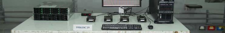
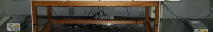

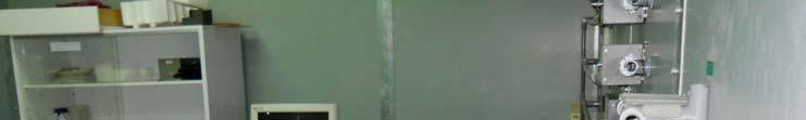


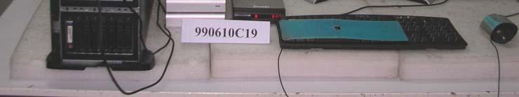
90 6 PHOTOGRAPHS OF THE TEST CONFIGURATION Conducted Emission Test Report No.: CE990610C19A 90 of 98 Report Format Version 5.0.1
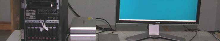
91 Radiated Emission Test (Frequency range 30MHz ~ 1GHz) Report No.: CE990610C19A 91 of 98 Report Format Version 5.0.1


92 Radiated Emission Test (Frequency range above 1GHz) Report No.: CE990610C19A 92 of 98 Report Format Version 5.0.1


93 Harmonics Emission Test & Voltage Fluctuation and Flicker Test ESD Test Report No.: CE990610C19A 93 of 98 Report Format Version 5.0.1


94 RS Test EFT Test Report No.: CE990610C19A 94 of 98 Report Format Version 5.0.1


95 Surge Test CS Test (Power line) Report No.: CE990610C19A 95 of 98 Report Format Version 5.0.1


96 CS Test (Mini SAS cable) Magnetic Test Report No.: CE990610C19A 96 of 98 Report Format Version 5.0.1

97 Voltage Dip and Interruption Test Report No.: CE990610C19A 97 of 98 Report Format Version 5.0.1
TEST REPORT. Building 6, XinXinTian Industrial Park, XinSha Road, ShaJing, Baoan District, ShenZhen, China. Shenzhen Innokin Technology Co.
 TEST REPORT Applicant Address Shenzhen Innokin Technology Co., Ltd Building 6, XinXinTian Industrial Park, XinSha Road, ShaJing, Baoan District, ShenZhen, China Manufacturer or Supplier Address Product
FCC DoC TEST REPORT. TESTED : Sep. 01 to 02, 2010 APPLICANT : LOGITECH FAR EAST LTD.
 FCC DoC TEST REPORT REPORT NO. : FD990901E04 MODEL NO. : Y-R0016 RECEIVED : Sep. 01, 2010 TESTED : Sep. 01 to 02, 2010 ISSUED DATE : Sep. 07, 2010 APPLICANT : LOGITECH FAR EAST LTD. ADDRESS : #2 Creation
FCC TEST REPORT. LAB ADDRESS: No. 47, 14 th Ling, Chia Pau Tsuen, Linko Hsiang 244, Taipei Hsien, Taiwan, R.O.C.
 FCC TEST REPORT REPORT NO.: RF951204L06A MODEL NO.: WRT54G V8 RECEIVED: Jan. 13, 2007 TESTED: Jan. 13 ~ Jan. 16, 2007 ISSUED: Jan. 17, 2007 APPLICANT: Cisco-Linksys LLC ADDRESS: 121 Theory Drive Irvine,
VCCI TEST REPORT. TESTED : June 22 to 23, 2010 APPLICANT : LOGITECH FAR EAST LTD.
 VCCI TEST REPORT REPORT NO. : V990621E07 MODEL NO. : M-U0026 RECEIVED : June 21, 2010 TESTED : June 22 to 23, 2010 ISSUED : June 24, 2010 APPLICANT : LOGITECH FAR EAST LTD. ADDRESS : #2 Creation Rd. 4,
FCC TEST REPORT th Lin, Chiapau Tsun, Linko, Taipei, Taiwan, R.O.C. No. 19, Hwa Ya 2 nd Rd., Kueishan, Taoyuan, Taiwan, R.O.C.
 FCC TEST REPORT REPORT NO.: RF941130L05 MODEL NO.: WAP54G ver. 3.1 RECEIVED: Jan. 23, 2006 TESTED: Jan. 23 ~ Feb. 27, 2006 ISSUED: Mar. 02, 2006 APPLICANT: Cisco-Linksys LLC ADDRESS: 121 Theory Drive Irvine,
FCC TEST REPORT (15.407)
") FCC TEST REPORT (15.407) REPORT : RF141108C01-1 MODEL : AP 100X FCC ID: 2ACTO-AP100X RECEIVED: Nov. 08, 2014 TESTED: Nov. 19 ~ Nov. 26, 2014 ISSUED: Dec. 02, 2014 APPLICANT: Sophos Ltd ADDRESS: The Pentagon,Abingdon,OX14
FCC TEST REPORT (15.407) REPORT : RF141108C01-1 MODEL : AP 100X FCC ID: 2ACTO-AP100X RECEIVED: Nov. 08, 2014 TESTED: Nov. 19 ~ Nov. 26, 2014 ISSUED: Dec. 02, 2014 APPLICANT: Sophos Ltd ADDRESS: The Pentagon,Abingdon,OX14
FCC Verification Test Report
 FCC Verification Test Report Report No.: Test Model: FV141111C02 SPC-2845 Series Model: Vecow SPC Series, SPC-2145, SPC-2845-W4, SPC-2845X, SPC-2845R, SPC-2845D, SPC-XXXXXXXXXX ( X can be 0-9, A-Z or blank
FCC TEST REPORT. ISSUED BY: Bureau Veritas Consumer Products Services (H.K.) Ltd., Taoyuan Branch
 Ltd., Taoyuan Branch") FCC TEST REPORT REPORT NO.: RF971218L04 MODEL NO.: ESR-9753 (Refer to item 3.1 for more detail) RECEIVED: Dec. 18, 2008 TESTED: Dec. 22 ~ Dec. 25, 2008 ISSUED: Dec. 31, 2008 APPLICANT: Senao Networks Inc.
FCC TEST REPORT REPORT NO.: RF971218L04 MODEL NO.: ESR-9753 (Refer to item 3.1 for more detail) RECEIVED: Dec. 18, 2008 TESTED: Dec. 22 ~ Dec. 25, 2008 ISSUED: Dec. 31, 2008 APPLICANT: Senao Networks Inc.
FCC DoC TEST REPORT. ADDRESS : #2 Creation Rd. 4, Science-Based Ind. Park Hsinchu Taiwan, R.O.C.
 FCC DoC TEST REPORT REPORT NO. : FD990811E03 MODEL NO. : A-E0001 RECEIVED : Aug. 11, 2010 TESTED : Aug. 13 to 17, 2010 ISSUED DATE : Aug. 20, 2010 APPLICANT : LOGITECH FAR EAST LTD. ADDRESS : #2 Creation
FCC Test Report. TD-W8961N, TD-W8961ND (refer to item 3.1 for more details)
") FCC Test Report Report No.: FCC ID: Test Model: RF150625C21 TE7TDW8961NDV4 TD-W8961N, TD-W8961ND (refer to item 3.1 for more details) Received Date: Jun. 25, 2014 Test Date: Jul. 03 ~ Sep. 15, 2015 Issued
FCC Test Report Report No.: FCC ID: Test Model: RF150625C21 TE7TDW8961NDV4 TD-W8961N, TD-W8961ND (refer to item 3.1 for more details) Received Date: Jun. 25, 2014 Test Date: Jul. 03 ~ Sep. 15, 2015 Issued
FCC DoC TEST REPORT. ADDRESS : #2 Creation Rd. 4, Science-Based Ind. Park Hsinchu Taiwan, R.O.C.
 FCC DoC TEST REPORT REPORT NO. : FD981207H01 MODEL NO. : N-I0004 RECEIVED : Dec 07, 2009 TESTED : Dec. 08, 2009 ISSUED: Dec. 14, 2009 APPLICANT : LOGITECH FAR EAST LTD. ADDRESS : #2 Creation Rd. 4, Science-Based
FCC TEST REPORT (RFID)
") FCC TEST REPORT (RFID) REPORT NO.: RF130923D14-2 MODEL NO.: DC-NU2-UMPC FCC ID: 2AA69001 RECEIVED: Sep. 23, 2013 TESTED: Oct. 11 ~ 17, 2013 ISSUED: Oct. 25, 2013 APPLICANT: Capsule Technologie SAS ADDRESS:
FCC TEST REPORT (RFID) REPORT NO.: RF130923D14-2 MODEL NO.: DC-NU2-UMPC FCC ID: 2AA69001 RECEIVED: Sep. 23, 2013 TESTED: Oct. 11 ~ 17, 2013 ISSUED: Oct. 25, 2013 APPLICANT: Capsule Technologie SAS ADDRESS:
TEST REPORT. The submitted sample of the above equipment has been tested for according to the requirements of the following standards:
 TEST REPORT Applicant Address Innokin Technology Co., Ltd Building 6, XinXinTian Industrial Park, XinSha Road, ShaJing, Baoan District, ShenZhen, China Manufacturer or Supplier Address Product Innokin
FCC TEST REPORT. ADDRESS: #2 Creation Rd. 4, Science-Based Ind. Park Hsinchu Taiwan, R.O.C.
 FCC TEST REPORT REPORT NO.: RF991014E04 MODEL NO.: M-R0018 FCC ID: JNZMR0018 RECEIVED: Oct. 14, 2010 TESTED: Oct. 19, 2010 ISSUED: Oct. 22, 2010 APPLICANT: LOGITECH FAR EAST LTD. ADDRESS: #2 Creation Rd.
FCC TEST REPORT (Bluetooth)
") FCC TEST REPORT (Bluetooth) REPORT NO.: RF130801C01D MODEL NO.: HB-2000 FCC ID: OGSHB2000 RECEIVED: Aug. 01, 2013 TESTED: Aug. 20 ~ Oct. 18, 2013 ISSUED: Oct. 21, 2013 APPLICANT: Applied Wireless identifications
FCC TEST REPORT (Bluetooth) REPORT NO.: RF130801C01D MODEL NO.: HB-2000 FCC ID: OGSHB2000 RECEIVED: Aug. 01, 2013 TESTED: Aug. 20 ~ Oct. 18, 2013 ISSUED: Oct. 21, 2013 APPLICANT: Applied Wireless identifications
FCC DoC TEST REPORT. ISSUED BY : Bureau Veritas Consumer Products Services (H.K.) Ltd., Taoyuan Branch Hsin Chu Laboratory
 Ltd., Taoyuan Branch Hsin Chu Laboratory") FCC DoC TEST REPORT REPORT NO. : FD110511E05 MODEL NO. : A-00033 RECEIVED : May 11, 2011 TESTED : May 13, 2011 ISSUED: June 30, 2011 APPLICANT : Logitech Inc. ADDRESS : 6505 Kaiser Drive, Fremont, CA 94555
FCC DoC TEST REPORT REPORT NO. : FD110511E05 MODEL NO. : A-00033 RECEIVED : May 11, 2011 TESTED : May 13, 2011 ISSUED: June 30, 2011 APPLICANT : Logitech Inc. ADDRESS : 6505 Kaiser Drive, Fremont, CA 94555
FCC 15B Test Report. : BTv4.0 Dual Mode USB Dongle. Address : Thompson Ave. / Lenexa, Kansas / / USA
 FCC 15B Test Report Equipment Model No. Brand Name Applicant : BTv4.0 Dual Mode USB Dongle : BT820 : Laird Technologies : Laird Technologies Address : 11160 Thompson Ave. / Lenexa, Kansas / 66219 / USA
FCC TEST REPORT (WLAN )
") FCC TEST REPORT (WLAN 15.247) REPORT NO.: RF140220D04 MODEL NO.: LAPAC1750 FCC ID: Q87-LAPAC1750 RECEIVED: Feb. 20, 2014 TESTED: Feb. 20 ~ Mar. 24, 2014 ISSUED: Apr. 14, 2014 APPLICANT: Linksys LLC ADDRESS:
FCC TEST REPORT (WLAN 15.247) REPORT NO.: RF140220D04 MODEL NO.: LAPAC1750 FCC ID: Q87-LAPAC1750 RECEIVED: Feb. 20, 2014 TESTED: Feb. 20 ~ Mar. 24, 2014 ISSUED: Apr. 14, 2014 APPLICANT: Linksys LLC ADDRESS:
EMC TEST REPORT. ADDRESS : #2 Creation Rd. 4, Science-Based Ind. Park Hsinchu Taiwan, R.O.C.
 EMC TEST REPORT REPORT NO. : RM110613E07 MODEL NO. : M-R0027 RECEIVED : June 13, 2011 TESTED : June 17, 2011 ISSUED : June 22, 2011 APPLICANT : LOGITECH FAR EAST LTD. ADDRESS : #2 Creation Rd. 4, Science-Based
FCC 15B Test Report. : Bluetooth 4.2 Dual Mode USB HCI Module (Refer to item for more details) (Refer to item for more details)
 (Refer to item for more details)") FCC 15B Test Report Equipment Model No. Brand Name Applicant Address Standard : Bluetooth 4.2 Dual Mode USB HCI Module (Refer to item 1.1.1 for more details) : BT850-SA (Refer to item 1.1.1 for more details)
FCC 15B Test Report Equipment Model No. Brand Name Applicant Address Standard : Bluetooth 4.2 Dual Mode USB HCI Module (Refer to item 1.1.1 for more details) : BT850-SA (Refer to item 1.1.1 for more details)
VCCI TEST REPORT. According to. V-3/ , TECHNICAL REQUIREMENTS, Class B ITE. Equipment : USB video camera. Model No. : V-U0017 / V-U0021
 VCCI TEST REPORT According to V-3/2009.04, TECHNICAL REQUIREMENTS, Class B ITE Equipment : USB video camera Model No. : V-U0017 / V-U0021 Applicant : Logitech Far East Ltd. 2 Creation Road IV, Science-Based
FCC TEST REPORT (15.407)
") FCC TEST REPORT (15.407) REPORT NO.: RF150508C06A-7 MODEL: WT2 FCC ID: A4R-WT2 RECEIVED: May 08, 2015 TESTED: Jun. 10, 2015 ~ Jun. 18, 2015 ISSUED: Aug. 05, 2016 APPLICANT: Google Inc. ADDRESS: 1600 Amphitheatre
FCC TEST REPORT (15.407) REPORT NO.: RF150508C06A-7 MODEL: WT2 FCC ID: A4R-WT2 RECEIVED: May 08, 2015 TESTED: Jun. 10, 2015 ~ Jun. 18, 2015 ISSUED: Aug. 05, 2016 APPLICANT: Google Inc. ADDRESS: 1600 Amphitheatre
FCC Test Report. Report No.: RF160715C03-1 FCC ID: PY Test Model: EX6150v2. Received Date: Jul. 11, Test Date: Jul. 15 ~ Aug.
 FCC Test Report Report No.: FCC ID: Test Model: RF160715C03-1 PY316100334 EX6150v2 Received Date: Jul. 11, 2016 Test Date: Jul. 15 ~ Aug. 02, 2016 Issued Date: Aug. 03, 2016 Applicant: NETGEAR Inc. Address:
FCC TEST REPORT. SendFar Technology Co., Ltd.
 FCC TEST REPORT REPORT NO.: RF921021R02 MODEL NO.: WPC-3110 RECEIVED: October 21, 2003 TESTED: November 14 ~ November 16, 2003 APPLICANT: ADDRESS: SendFar Technology Co., Ltd. 15FL., NO.866-2, JUNGJENG
TEST REPORT. Building 6,XinXinTian Industrial Park, XinSha Road, ShaJing, Baoan District, ShenZhen, China
 TEST REPORT Applicant Address Innokin Technology Co.,Ltd Building 6,XinXinTian Industrial Park, XinSha Road, ShaJing, Baoan District, ShenZhen, China Manufacturer or Supplier Address Product Innokin Technology
EMC TEST REPORT. according to
 EMC TEST REPORT according to European Standard EN 55022:2006/A1:2007 Class B, EN 61000-3-2:2006, EN 61000-3-3:1995/A1:2001/A2:2006, EN 55024:1998/A1:2001/A2:2003 (IEC 61000-4-2:Edition 1.2:2001-04, IEC
FCC Test Report (15.249)
") FCC Test Report (15.249) Report No.: FCC ID: Test Model: RF150529E01 JNZNR0010 N-R0010 Received Date: May 29, 2015 Test Date: June 04 to 08, 2015 Issued Date: June 16, 2015 Applicant: LOGITECH FAR EAST
FCC Test Report (15.249) Report No.: FCC ID: Test Model: RF150529E01 JNZNR0010 N-R0010 Received Date: May 29, 2015 Test Date: June 04 to 08, 2015 Issued Date: June 16, 2015 Applicant: LOGITECH FAR EAST
FCC TEST REPORT (WLAN )
") FCC TEST REPORT (WLAN 15.247) REPORT : RF130923D14 MODEL : DC-NU2-UMPC FCC ID: 2AA69001 RECEIVED: Sep. 23, 2013 TESTED: Sep. 24 ~ Oct. 24, 2013 ISSUED: Oct. 25, 2013 APPLICANT: Capsule Technologie SAS
FCC TEST REPORT (WLAN 15.247) REPORT : RF130923D14 MODEL : DC-NU2-UMPC FCC ID: 2AA69001 RECEIVED: Sep. 23, 2013 TESTED: Sep. 24 ~ Oct. 24, 2013 ISSUED: Oct. 25, 2013 APPLICANT: Capsule Technologie SAS
FCC Test Report R Lumewave IoT Platform
 FCC Test Report Report No.: FCC ID: Test Model: Series Model: RF170620C22-3 Y6S-IOTADV IoT Platform Advance 72201R Lumewave IoT Platform Received Date: Apr. 26, 2017 Test Date: Jul. 03 ~ Aug. 31, 2017
FCC Test Report. Report No.: RF160715C03 FCC ID: PY Test Model: EX6150v2. Received Date: Jul. 11, Test Date: Jul. 15 ~ Aug.
 FCC Test Report Report No.: FCC ID: Test Model: RF160715C03 PY316100334 EX6150v2 Received Date: Jul. 11, 2016 Test Date: Jul. 15 ~ Aug. 02, 2016 Issued Date: Aug. 03, 2016 Applicant: NETGEAR Inc. Address:
CE EMC Test Certification
 Certification No.: EC57C001 CE EMC Test Certification According to European Standard EN 55022:1998/A1:2000/A2:2003 Class A, EN 61000-3-2: 2000, EN 61000-3-3:1995/A1:2001 and EN 55024:1998/A1:2001/A2:2003
VCCI TEST REPORT. According to. Class B ITE. Equipment : USB video camera
 VCCI TEST REPORT According to Class B ITE Equipment : USB video camera Model No. : V-U0011 Applicant : Logitech Far East Ltd. 2 Creation Road IV, Science-Based Ind. Park, Hsinchu, Taiwan. The test result
FCC TEST REPORT. Summit Data Communications, Inc. Advance Data Technology Corporation
 FCC TEST REPORT REPORT NO.: RF950331L08 MODEL NO.: SDC-MCF10G RECEIVED: Jun. 05, 2006 TESTED: Jun. 05 ~ 22, 2006 ISSUED: Jun. 26, 2006 APPLICANT: ADDRESS: Summit Data Communications, Inc. 526 South Main
FCC Test Report. Report No.: RF170922C07 FCC ID: 2AGDE-WRT3061. Test Model: WRT3061. Received Date: Sep. 22, 2017
 FCC Test Report Report No.: RF170922C07 FCC ID: 2AGDE-WRT3061 Test Model: WRT3061 Received Date: Sep. 22, 2017 Test Date: Oct. 11, 2017 ~ Oct. 17, 2017 Issued Date: Nov. 29, 2017 Applicant: WondaLink Inc.
CE EMC TEST REPORT. TESTED : June 22 to 23, 2010 APPLICANT : LOGITECH FAR EAST LTD.
 CE EMC TEST REPORT REPORT NO. : CE990621E07 MODEL NO. : M-U0026 RECEIVED : June 21, 2010 TESTED : June 22 to 23, 2010 ISSUED : June 24, 2010 APPLICANT : LOGITECH FAR EAST LTD. ADDRESS : #2 Creation Rd.
TEST REPORT. 4F,-4, No.669 Jingping Rd., Zhonghe City, TaiPei county 235, Taiwan R.O.C.
 TEST REPORT Applicant: Address: Asian Express Holding Ltd. 4F,-4, No.669 Jingping Rd., Zhonghe City, TaiPei county 235, Taiwan R.O.C. Manufacturer or Supplier Address Product: Brand Name: Asian Express
FCC C2PC Test Report
 FCC C2PC Test Report FCC ID Equipment Model No. Brand Name Applicant : SQGBT800 : BTv4.0 Dual Mode USB Dongle : BT820 : Laird Technologies : Laird Technologies Address : 11160 Thompson Ave. / Lenexa, Kansas
FCC Test Report RF141003E10B-1. Report No.: PY FCC ID: EX6150. Test Model: Received Date: Apr. 17, Test Date: Apr. 22 to July 21, 2015
 FCC Test Report Report No.: FCC ID: Test Model: RF141003E10B-1 PY314300283 EX6150 Received Date: Apr. 17, 2015 Test Date: Apr. 22 to July 21, 2015 Issued Date: Aug. 03, 2015 Applicant: NETGEAR, Inc. Address:
EN RF Test Report
 EN 300 440 RF Test Report Report No.: Test Model: RE150707C22B EYAGJN Received Date: Jul. 07, 2015 Test Date: Jul. 14, 2015 Issued Date: Apr. 14, 2017 Applicant: TAIYO YUDEN CO., LTD. Address: 8-1, Sakae-cho,
CE TEST CERTIFICATION
 according to Certification No.: E5NC004 European Standard EN 61000-6-4:2001 EN 61000-3-2: 2000, EN 61000-3-3:1995/A1:2001 and EN 61000-6-2:2001 ( IEC 61000-4-2:1995/A1:1998, IEC 61000-4-3: 1995/A1:1998,
FCC 15B Test Report. : Bluetooth 4.2 module (BLE only) (Refer to item for more details)
 (Refer to item for more details)") FCC 15B Test Report Equipment Model No. Brand Name Applicant Address Standard : Bluetooth 4.2 module (BLE only) : BL652-SA, BL652-SC (Refer to item 1.1.1 for more details) : Laird Technologies : Laird
FCC 15B Test Report Equipment Model No. Brand Name Applicant Address Standard : Bluetooth 4.2 module (BLE only) : BL652-SA, BL652-SC (Refer to item 1.1.1 for more details) : Laird Technologies : Laird
FCC 15B Test Report. : ac/a/b/g/n + Bluetooth 4.2 module (please refer to section for more details.)
") FCC 15B Test Report Equipment Model No. Brand Name Applicant Address Standard : 802.11 ac/a/b/g/n + Bluetooth 4.2 module (please refer to section 1.1.1 for more details.) : ST60-2230C (please refer to
FCC 15B Test Report Equipment Model No. Brand Name Applicant Address Standard : 802.11 ac/a/b/g/n + Bluetooth 4.2 module (please refer to section 1.1.1 for more details.) : ST60-2230C (please refer to
EN 55015: 2013 Clause Pass. EN 55015: 2013 Clause Pass. EN 55015: 2013 Clause Pass
 Reference No.: WTD15S0730643E Page 2 of 42 1 Test Summary Test Item Conducted Disturbance at Mains Terminal, 9kHz to 30MHz Radiation electromagnetic disturbance, 9kHz to 30MHz Radiation Emission, 30MHz
EN 55022: 2010+AC:2011 Clause 6.1 Pass. Harmonic Current EN :2006+A1:2009+A2:2009 Class A N/A
 Reference No.: WT12106773-N-S-E Page 2 of 33 1 Test Summary Test Item Mains Terminal Disturbance Voltage, 150KHz to 30MHz Radiation Emission, 30MHz to 1000MHz EMISSION Test Standard Class / Severity Result
EMI Test Report. : BTv4.0 Dual Mode USB Dongle
 EMI Test Report Equipment Model No. Brand Name Applicant Address Standard : BTv4.0 Dual Mode USB Dongle : BT820 : Laird Technologies : Laird Technologies Received Date : Jan. 23, 2017 W66N220 Commerce
CE TEST CERTIFICATION
 Certification No.: E5DC001 according to European Standard EN 61000-6-4:2001 EN 61000-3-2: 2000, EN 61000-3-3:1995/A1:2001 and EN 61000-6-2:2001 ( IEC 61000-4-2:1995/A1:1998, IEC 61000-4-3: 1995/A1:1998,
EMC TEST REPORT. Report No.: CE10-LIE040101E
 EMC TEST REPORT Report No.: CE10-LIE040101E Product: LED TUBE Model No.: T10, T8, T5 Applicant: Shenzhen Saiju Electronic Co., Ltd. Address: 2nd. Xianshun Industrial Park, Gushu, Xixiang, Bao an, Shenzhen,
CE EMC TEST REPORT. LAB LOCATION : No. 81-1, Lu Liao Keng, 9 Ling, Wu Lung Tsuen, Chiung Lin Hsiang, Hsin Chu Hsien, Taiwan
 CE EMC TEST REPORT REPORT NO. : CE951115H04B MODEL NO. : MD15 RECEIVED : Nov. 27, 2006 TESTED : Dec. 04 to 27, 2006 ISSUED: March 07, 2007 APPLICANT : CTC UNION TECHNOLOGIES CO., LTD. ADDRESS : 8F, No.
CE EMC TEST REPORT VIVOTEK INC.
 CE EMC TEST REPORT REPORT NO.: CE921001R05 MODEL NO.: IP 2112 / IP 2122 RECEIVED: October 16, 2003 TESTED: October 16~ November 03, 2003 APPLICANT: ADDRESS: VIVOTEK INC. 6F, No.192, Lien-Chen Rd., Chung-Ho,
FCC Test Report. Zebra Technologies Corporation. Zebra Technologies Corporation
 FCC Test Report Report No.: FCC ID: Test Model: RF170427C12-6 UZ7TC25AJ TC25AJ Received Date: Apr. 27, 2017 Test Date: May 06 ~ Aug. 16, 2017 Issued Date: Sep. 14, 2017 Applicant: Zebra Technologies Corporation
FCC TEST REPORT. ISSUED BY: Bureau Veritas Consumer Products Services (H.K.) Ltd., Taoyuan Branch
 Ltd., Taoyuan Branch") FCC TEST REPORT REPORT NO.: RF140730D07 MODEL NO.: F5L174 FCC ID: K7SF5L174 RECEIVED: Jul. 30, 2014 TESTED: Aug. 22 ~ 28, 2014 ISSUED: Aug. 29, 2014 APPLICANT: Belkin International, Inc. ADDRESS: 12045
FCC TEST REPORT REPORT NO.: RF140730D07 MODEL NO.: F5L174 FCC ID: K7SF5L174 RECEIVED: Jul. 30, 2014 TESTED: Aug. 22 ~ 28, 2014 ISSUED: Aug. 29, 2014 APPLICANT: Belkin International, Inc. ADDRESS: 12045
FCC TEST REPORT. ISSUED BY: Bureau Veritas Consumer Products Services (H.K.) Ltd., Taoyuan Branch
 Ltd., Taoyuan Branch") FCC TEST REPORT REPORT NO.: RF140728D03 MODEL NO.: F5L171 FCC ID: K7SF5L171 RECEIVED: Jul. 28, 2014 TESTED: Aug. 21 ~ 22, 2014 ISSUED: Aug. 26, 2014 APPLICANT: Belkin International, Inc. ADDRESS: 12045
FCC TEST REPORT REPORT NO.: RF140728D03 MODEL NO.: F5L171 FCC ID: K7SF5L171 RECEIVED: Jul. 28, 2014 TESTED: Aug. 21 ~ 22, 2014 ISSUED: Aug. 26, 2014 APPLICANT: Belkin International, Inc. ADDRESS: 12045
FCC Test Report. (For 5.18 ~ 5.24GHz, ~ 5.825GHz) 5455 Great America Parkway, Santa Clara, CA USA
 5455 Great America Parkway, Santa Clara, CA USA") FCC Test Report (For 5.18 ~ 5.24GHz, 5.745 ~ 5.825GHz) Report No.: FCC ID: Test Model: RF170417C09-1 2AKCZ-0C1 APL42-0C1 Received Date: Apr. 17, 2017 Test Date: Apr. 28 ~ Jun. 06, 2017 Issued Date: Jun.
FCC Test Report (For 5.18 ~ 5.24GHz, 5.745 ~ 5.825GHz) Report No.: FCC ID: Test Model: RF170417C09-1 2AKCZ-0C1 APL42-0C1 Received Date: Apr. 17, 2017 Test Date: Apr. 28 ~ Jun. 06, 2017 Issued Date: Jun.
FCC Verification Test Report
 FCC Verification Test Report Report No.: Test Model: FV130424E06E VC-A50, PTC-120 Series Model: VC-X50, VC-X30, VC-501, VC-502, VC-301, VC-302, VC-302X, VC-502X, VC-A50X (where X can be A to Z for marketing
TEST REPORT. Table of Contents
 Page:2 of 24 Table of Contents 1. DOCUMENT POLICY AND TEST STATEMENT... 3 1.1 DOCUMENT POLICY...3 1.2 TEST STATEMENT...3 2. DESCRIPTION OF EUT AND TEST MODE... 4 2.1 GENERAL DESCRIPTION OF EUT...4 2.2
Prepared for Address. : KST DIGITAL TECHNOLOGY LIMITED : No.226, Pangu Street, Meixian, Meizhou, Guangdong. Prepared by
 EMC TEST REPORT For KST DIGITAL TECHNOLOGY LIMITED Coreless Servo Model No.: X12-508 Additional Model No.: DS215MG, DS315MG, DS213MG, DS313MG, DS12C, DS12T, X12-306 Prepared for Address : KST DIGITAL TECHNOLOGY
TEST REPORT. Table of Contents
 Page:2 of 28 Table of Contents 1. DOCUMENT POLICY AND TEST STATEMENT... 3 1.1 DOCUMENT POLICY... 3 1.2 TEST STATEMENT... 3 2. DESCRIPTION OF EUT AND TEST MODE... 4 2.1 GENERAL DESCRIPTION OF EUT... 4 2.2
EMI Test Report. W66N220 Commerce Court, Cedarburg, Wisconsin 53012, USA : CISPR 32:2015/COR1:2016, Class B AS/NZS CISPR 32:2015, Class B
 EMI Test Report Equipment Model No. Brand Name Applicant Address Standard : Bluetooth 5.0 BLE Dongle : BL654 : Laird : Laird Technologies Received Date : Jan. 30, 2018 W66N220 Commerce Court, Cedarburg,
Discontinuous Disturbance (Click) EN :2006+A1:2009+A2:2011 Clause N/A** Radiated Emission, 30MHz to 1000MHz
 EN :2006+A1:2009+A2:2011 Clause N/A** Radiated Emission, 30MHz to 1000MHz") Reference No.: WTN13F0706038E Page 2 of 40 1 Test Summary Test Item Mains Terminal Disturbance Voltage, 148.5kHz to 30MHz Disturbance Power, 30MHz to 300MHz EMISSION Test Standard Class / Severity Result
Reference No.: WTN13F0706038E Page 2 of 40 1 Test Summary Test Item Mains Terminal Disturbance Voltage, 148.5kHz to 30MHz Disturbance Power, 30MHz to 300MHz EMISSION Test Standard Class / Severity Result
Harmonic Current emission EN :2014 Class A Pass. Voltage Fluctuation and Flicker EN :2013 Clause 5 Pass
 Reference No.: WTS15F0323845E Page 2 of 33 1 Test Summary Test Item Mains Terminal Disturbance Voltage, 148.5kHz to 30MHz Disturbance Power, 30MHz to 300MHz Discontinuous Disturbance (Click) Radiated Emission,
Supplemental Transmit Simultaneously Test Report
 Supplemental Transmit Simultaneously Test Report REPORT NO.: RF141003E10-2 MODEL NO.: EX6150 FCC ID: PY314300283 RECEIVED: Oct. 03, 2014 TESTED: Oct. 09 to Dec. 08, 2014 ISSUED: Jan. 12, 2015 APPLICANT:
EMC TEST REPORT For MPP SOLAR INC Inverter/ Charger Model Number : PIP 4048HS
 EMC-E20130903E EMC TEST REPORT For MPP SOLAR INC Inverter/ Charger Model Number : PIP 4048HS Prepared for : MPP SOLAR INC Address : 4F, NO. 50-1, SECTION 1, HSIN-SHENG S. RD. TAIPEI, TAIWAN Prepared by
FCC TEST REPORT. for. 47 CFR, Part 15, Subpart C. SPORTON International Inc.
 FCC TEST REPORT for 47 CFR, Part 15, Subpart C Equipment Trade Name Model No. FCC ID Filing Type Applicant : GamePad : Genius : Wireless G-12X : FSUGG0005 : Certification : KYE Systems Corp. No. 492, Sec.
EMC TEST REPORT. Report No.: TS EME Model No.: 33XR-A Issued Date: Jan. 08, 2009
 Page 1 of 18 EMC TEST REPORT Report No.: TS08100063-EME Model No.: 33XR-A Issued Date: Jan. 08, 2009 Applicant: Test Method/ Standard: Test By: FLUKE CORP. 6920 Seaway Blvd, M/S 266D Everett, WA 98203
ITUNER NETWORKS CORPORATION EMC REPORT Fremont Blvd. Fremont, CA
 Shenzhen BST Technology Co., Ltd. ITUNER NETWORKS CORPORATION EMC REPORT Prepared For : ITUNER NETWORKS CORPORATION 47801 Fremont Blvd. Fremont, CA. 94538 Product Name: PicoPSU-150 Trade Name: PicoPSU
Equipment : UPS Brand Name : Test Model No. : SRT3000RMXLW-IEC Multiple Listing :
 Equipment : UPS Brand Name : Test Model No. : SRT3000RMXLW-IEC Multiple Listing : SRT3000RMXLTxxxxxxxxxx SRT (means series name) 3000 (means maximum VA output) RM (means Rack Mounted) or none (means Tower
FCC C2PC Test Report
 FCC C2PC Test Report FCC ID Equipment Model No. Brand Name Applicant Address : TLZ-NM230NF : IEEE 802.11 b/g/n Wireless LAN and Bluetooth combo M.2 1216 module : AW-NM230NF-H : AzureWave : AzureWave Technologies,
EMC TEST REPORT. NORTE SIRIUS ENTERPRISE CO., LTD , Shin-Sheng St., Chung-Ho Dist, New Taipei City, Taiwan
 Page 1 of 32 EMC TEST REPORT Report No.: TS11020117-EME Model No.: NS-PSE, NS-POINTED, NS-PSQUARE, NS-PF-S, NS-PT, NS-PR, NS-PU, NS-PF-H, NS-BALIBA, NS-FLEXMA Issued Date: Mar. 01, 2011 Applicant: NORTE
FCC DoC Test Report. Series Model: xxxzeus-248yt-xxxxxxx (The "y" is E & S,"x" Can be 0 to 9 & A to Z,"-" or blank ) Received Date: Feb.
 Received Date: Feb.") FCC DoC Test Report Report No.: FD160805D06B Test Model: Zeus-248ST-A1-0101 Series Model: xxxzeus-248yt-xxxxxxx (The "y" is E & S,"x" Can be 0 to 9 & A to Z,"-" or blank ) Received Date: Feb. 9, 2017 Test
FCC DoC Test Report Report No.: FD160805D06B Test Model: Zeus-248ST-A1-0101 Series Model: xxxzeus-248yt-xxxxxxx (The "y" is E & S,"x" Can be 0 to 9 & A to Z,"-" or blank ) Received Date: Feb. 9, 2017 Test
FCC Test Report (IEEE )
") FCC Test Report (IEEE 802.15.4) Report No.: RF170714C04A-1 FCC ID: ZQAH17 Test Model: A0078 Received Date: July 14, 2017 Test Date: July 26 to Aug. 26, 2017 Issued Date: Sep. 08, 2017 Applicant: Nest Labs,
FCC Test Report (IEEE 802.15.4) Report No.: RF170714C04A-1 FCC ID: ZQAH17 Test Model: A0078 Received Date: July 14, 2017 Test Date: July 26 to Aug. 26, 2017 Issued Date: Sep. 08, 2017 Applicant: Nest Labs,
EMC REPORT. ShenZhen KY Technology Co.,Ltd. No.369, BaoTian 1st RD, TieGang Industrial Park, Xixiang Town, Baoan District, ShenZhen, PRC.
 Report No.: UNI2016121702ER-01 Page 1 / 30 ShenZhen KY Technology Co.,Ltd EMC REPORT Prepared For: ShenZhen KY Technology Co.,Ltd Product Name: Smart bracelet No.369, BaoTian 1st RD, TieGang Industrial
CE EMC TEST REPORT. ADDRESS: No. 25, Wu-Gong 6th Rd., Wu Ku Industrial Park, Taipei Hsien, Taiwan, R. O. C.
 CE EMC TEST REPORT REPORT NO.: CE990923D04 MODEL NO.: Y-U0012 RECEIVED: Sep. 23, 2010 TESTED: Sep. 24 ~ 29, 2010 ISSUED: Sep. 30, 2010 APPLICANT: Chicony Electronics Co., Ltd. ADDRESS: No. 25, Wu-Gong
TEST SUMMARY. Prüfbericht - Nr.: Test Report No.: Seite 2 von 27. Page 2 of 27
 15072768 001 Seite 2 von 27 Page 2 of 27 TEST SUMMARY 4.1.1 HARMONICS ON AC MAINS 4.1.2 VOLTAGE CHANGES, VOLTAGE FLUCTUATIONS AND FLICKER ON AC MAINS 4.1.3 MAINS TERMINAL CONTINUOUS DISTURBANCE VOLTAGE
CONFORMANCE TEST REPORT FOR EN /-6
 CONFORMANCE TEST REPORT FOR EN 301489-1/-6 Client: Product: Model: Manufacturer/supplier: Aztech Systems Limited DECT Phone H315-S1 (FP) Aztech Systems Limited Date test item received: 2006/05/09 Date
FCC Test Report (PART 24)
") FCC Test Report (PART 24) Report No.: RF171016C36 FCC ID: 2AGDE-WRT3061 Test Model: WRT3061 Received Date: Oct. 16, 2017 Test Date: Nov. 04, 2017 ~ Dec. 07, 2017 Issued Date: Dec. 07, 2017 Applicant: WondaLink
FCC Test Report (PART 24) Report No.: RF171016C36 FCC ID: 2AGDE-WRT3061 Test Model: WRT3061 Received Date: Oct. 16, 2017 Test Date: Nov. 04, 2017 ~ Dec. 07, 2017 Issued Date: Dec. 07, 2017 Applicant: WondaLink
Shenzhen Toby Technology Co., Ltd. EMC Test Report. Report No.: TB-EMC Page: 1 of 20
 Shenzhen Toby Technology Co., Ltd. Report No.: TB-EMC125641 Page: 1 of 20 EMC Test Report Application No. : TB12114299 Applicant : Newmb Technology Co., Ltd. Equipment Under Test (EUT) EUT Name : USB HUB
TEST REPORT... 1 CONTENT...
 CONTENT TEST REPORT... 1 CONTENT... 2 1 TEST RESULTS SUMMARY... 3 2 EMC RESULTS CONCLUSION... 4 3 LABORATORY MEASUREMENTS... 6 4 EMI TEST... 7 4.1 CONTINUOUS CONDUCTED DISTURBANCE VOLTAGE TEST... 7 4.2
FCC Test Report. RBS50, SRR60, SRS60 (refer to item 3.1 for more details)
") FCC Test Report Report No.: FCC ID: Test Model: Series Mode: RF160621C27V PY316200341 RBR50 RBS50, SRR60, SRS60 (refer to item 3.1 for more details) Received Date: May 16, 2018 Test Date: May 18 ~ May
FCC Test Report Report No.: FCC ID: Test Model: Series Mode: RF160621C27V PY316200341 RBR50 RBS50, SRR60, SRS60 (refer to item 3.1 for more details) Received Date: May 16, 2018 Test Date: May 18 ~ May
FCC 47 CFR PART 15 SUBPART B
 FCC 47 CFR PART 15 SUBPART B TEST REPORT For DC TO DC CONVERTER Model : D100 Series Issued for MicroPower Direct, LLC 232 Tosca Drive Stoughton, MA02072 U.S.A. Issued by Compliance Certification Services
Discontinuous Disturbance (Click) EN : 2011 Clause Pass Radiated Emission, 30MHz to 1000MHz
 EN : 2011 Clause Pass Radiated Emission, 30MHz to 1000MHz") Reference No.: WTU15U0933879E Page 2 of 45 1 Test Summary Test Item Mains Terminal Disturbance Voltage, 148.5kHz to 30MHz Disturbance Power, 30MHz to 300MHz EMISSION Test Standard Class / Severity Result
Reference No.: WTU15U0933879E Page 2 of 45 1 Test Summary Test Item Mains Terminal Disturbance Voltage, 148.5kHz to 30MHz Disturbance Power, 30MHz to 300MHz EMISSION Test Standard Class / Severity Result
FCC Test Report. : ASE Group 4F,No 133, Sec 4, Mingsheng E Rd, Songshan Dist, Taipei, Taiwan
 FCC Test Report Equipment : Wireless Pedometer/Tracker Brand Name : ASE Group Model No. : M903 Standard : 47 CFR FCC Part 15B Device Class : Class B Applicant Manufacturer : ASE Group 4F,No 133, Sec 4,
Equipment : AC/DC ADAPTER Test Model No. : ADP-90MD H Applicant : DELTA ELECTRONICS, INC. Test Report No. : CE130910D06
 Equipment : AC/DC ADAPTER Test Model No. : ADP-90MD H Applicant : DELTA ELECTRONICS, INC. Test Report No. : CE130910D06 We, Bureau Veritas Consumer Products Services (H.K.) Ltd., Taoyuan Branch, declare
TEST REPORT. Table of Contents
 Page:2 of 43 Table of Contents 1. DOCUMENT POLICY AND TEST STATEMENT... 4 1.1 DOCUMENT POLICY... 4 1.2 TEST STATEMENT... 4 2. DESCRIPTION OF EUT AND TEST MODE... 4 2.1 GENERAL DESCRIPTION OF EUT... 4 2.2
FCC TEST REPORT. Cisco-Linksys LLC. 121 Theory Drive, Irvine, CA (USA) Advance Data Technology Corporation
 Advance Data Technology Corporation") FCC TEST REPORT REPORT NO.: RF940919L07 MODEL NO.: WMP54G ver. 4.1 RECEIVED: Sep. 19, 2005 TESTED: Sep. 19 ~ Sep. 22, 2005 ISSUED: Sep. 23, 2005 APPLICANT: ADDRESS: Cisco-Linksys LLC 121 Theory Drive,
FCC TEST REPORT REPORT NO.: RF940919L07 MODEL NO.: WMP54G ver. 4.1 RECEIVED: Sep. 19, 2005 TESTED: Sep. 19 ~ Sep. 22, 2005 ISSUED: Sep. 23, 2005 APPLICANT: ADDRESS: Cisco-Linksys LLC 121 Theory Drive,
TEST SUMMARY. Prüfbericht - Nr.: Test Report No.: Seite 2 von 25. Page 2 of 25
 15072259 001 Seite 2 von 25 Page 2 of 25 TEST SUMMARY 4.1.1 HARMONICS ON AC MAINS 4.1.2 VOLTAGE FLUCTUATIONS ON AC MAINS 4.1.3 MAINS TERMINAL CONTINUOUS DISTURBANCE VOLTAGE 4.1.4 DISCONTINUOUS INTERFERENCE
IC Test Report. : 3147A-BT900US : Intelligent BT4.0 Dual Mode USB Dongle
 IC Test Report IC Equipment Model No. Brand Name Applicant : 3147A-BT900US : Intelligent BT4.0 Dual Mode USB Dongle : BT900-US : Laird Technologies : Laird Technologies Address : 11160 Thompson Ave., Lenexa,
EMC test report AU01+E04
 Customer: Altuflevskoye shosse,h.48,bld.1pr.1,room39 Moscow,127566 Russia EMC test report 130504-AU01+E04 This test report may not be copied or published in a part without the written authorization of
FCC TEST REPORT (Z-Wave)
") FCC TEST REPORT (Z-Wave) REPORT NO.: RF130927E08E-2 MODEL NO.: FiOS-G1100 FCC ID: 2ABTEG1100 RECEIVED: Sep. 27, 2013 TESTED: Oct. 07 to Dec. 06, 2013 ISSUED: Mar. 21, 2014 APPLICANT: Verizon Online LLC
FCC TEST REPORT (Z-Wave) REPORT NO.: RF130927E08E-2 MODEL NO.: FiOS-G1100 FCC ID: 2ABTEG1100 RECEIVED: Sep. 27, 2013 TESTED: Oct. 07 to Dec. 06, 2013 ISSUED: Mar. 21, 2014 APPLICANT: Verizon Online LLC
EMC TEST REPORT. Report No. : EM/2004/10096 Page : 1 of 19
 EMC TEST REPORT Page : 1 of 19 Equipment Under Test Model No. Applicant Address of Applicant : Bluetooth Headset : FB-HS01 : Formosa Teletek Corporation : 358, Huaya 2 nd Rd., Gueishan shiang, Taoyuan,
EMC TEST REPORT. For. Switching Mode Power Adaptor. Model No.: 9W/14.4V/EU(18V/1.0A), 19W/14.4V/EU(12V/1.5A)
, 19W/14.4V/EU(12V/1.5A)") EMC TEST REPORT For Company Limited Liability «Faraday Electronics» Switching Mode Power Adaptor Model No.: 9W/14.4V/EU(18V/1.0A), 19W/14.4V/EU(12V/1.5A) Prepared For : Company Limited Liability «Faraday
EMC TEST REPORT For Company Limited Liability «Faraday Electronics» Switching Mode Power Adaptor Model No.: 9W/14.4V/EU(18V/1.0A), 19W/14.4V/EU(12V/1.5A) Prepared For : Company Limited Liability «Faraday
EMC TEST REPORT For ShenZhen ZhangQing Electronic LTD poe tester Model No.: WS POE Tester/Detector Additional Model No: Please Refer to Page 8
 EMC TEST REPORT For ShenZhen ZhangQing Electronic LTD poe tester Model No.: WS POE Tester/Detector Additional Model No: Please Refer to Page 8 Prepared for Address : ShenZhen ZhangQing Electronic LTD :
Test Report. Applicant ASUSTeK COMPUTER INC. 4F, No. 150, Li-Te Rd., Peitou, Taipei, Taiwan. Date of Receipt Jan. 28, Issued Date Mar.
 Test Report Product Name Model No. FCC ID. IC ID. WPC Qi 1.1/1.0 compliance wireless charging micro-usb box Wireless Charger MSQ-ASUSWLCHARGER 3568A-ASWLCHARGER Applicant ASUSTeK COMPUTER INC. Address
CE EMC TEST REPORT. according to. EN V1.4.1 ( ) and EN V1.2.1 ( ) Equipment : WIRELESS 11B CARDBUS CARD
 and EN V1.2.1 ( ) Equipment : WIRELESS 11B CARDBUS CARD") CE EMC TEST REPORT according to EN 301 489-1 V1.4.1 (2002-08) and EN 301 489-17 V1.2.1 (2002-08) Equipment : WIRELESS 11B CARDBUS CARD Model No. Applicant : CB11B2, MS-6829 : Micro-Star Int l Co., Ltd.
CE EMC TEST REPORT according to EN 301 489-1 V1.4.1 (2002-08) and EN 301 489-17 V1.2.1 (2002-08) Equipment : WIRELESS 11B CARDBUS CARD Model No. Applicant : CB11B2, MS-6829 : Micro-Star Int l Co., Ltd.
FCC 47 CFR PART 15 SUBPART B TEST REPORT
 FCC 47 CFR PART 15 SUBPART B TEST REPORT for 10.4 Rugged Tablet PC Model: R10V28M-VMXXXX (X=A~Z, a~z, 0 ~9, Blank or Slash) Test Report Number: 80808002-D Issued for Winmate Communication INC. 9F, No.
FCC Test Report (Zigbee)
") FCC Test Report (Zigbee) Report No.: RF170419E07A-4 FCC ID: HD5-3GSTTHALPC1 Test Model: 3G-ST-THALP-C1 Received Date: Apr. 24, 2017 Test Date: May 04 to June 01, 2017 Issued Date: June 15, 2017 Applicant:
FCC Test Report (Zigbee) Report No.: RF170419E07A-4 FCC ID: HD5-3GSTTHALPC1 Test Model: 3G-ST-THALP-C1 Received Date: Apr. 24, 2017 Test Date: May 04 to June 01, 2017 Issued Date: June 15, 2017 Applicant:
FCC SUPPLEMENTARY TEST REPORT
 FCC SUPPLEMENTARY TEST REPORT REPORT NO.: RF960612H07C MODEL NO.: WRP400 RECEIVED: Apr. 24, 2009 TESTED: June 05 to July 10, 2009 ISSUED: July 13, 2009 APPLICANT: Cisco-Linksys LLC ADDRESS: 121 Theory
EMC TEST REPORT. : 4F, No. 50-1, Section 1, Hsin-Sheng S. Rd. Taipei, Taiwan. Taiwan
 EMC TEST REPORT For MPP SOLAR INC Model Number: PIP 2424MS Prepare for Address : MPP Solar Inc : 4F, No. 50-1, Section 1, Hsin-Sheng S. Rd. Taipei, Taiwan Prepare by Address : MPP Solar In : 4F, No. 50-1,
TEST REPORT. draft draft draft. TRF Originator...: Shenzhen CTL Testing Technology Co., Ltd. Master TRF...: Dated
 Shenzhen CTL Testing Technology Co., Ltd. Tel: +86-755-89486194 Fax: +86-755-26636041 TEST REPORT EN 55014-1 / EN 55014-2 Electromagnetic compatibility Requirements for household appliances, electric tools
EMC VERIFICATION SUMMARY Report No.: SZHH
 EMC VERIFICATION SUMMARY Toy ITE Others Additional Models: 0801 to 0899 INCLUSIVE, 0804, 0804W, 0805, 0806, 0807, 0808, 0809, 0811, 0811W, 0812, 0813, 0814,0815, 0816, 0817,0817 ROOM 619, 6/F. PENINSULA
FCC Test Report (Zigbee-Thread)
") FCC Test Report (Zigbee-Thread) Report No.: RF160818E07B-7 FCC ID: G95TCA301 Test Model: TCA301TCH1 Series Model: TCA301TCH2, TCA301ROG1, TCA301COX2, TCA301BHN2, TCA301CMP2, TCA301TWC2 Received Date: Apr.
FCC Test Report (Zigbee-Thread) Report No.: RF160818E07B-7 FCC ID: G95TCA301 Test Model: TCA301TCH1 Series Model: TCA301TCH2, TCA301ROG1, TCA301COX2, TCA301BHN2, TCA301CMP2, TCA301TWC2 Received Date: Apr.