CE EMC TEST REPORT VIVOTEK INC.
|
|
|
- Jayson Clark
- 5 years ago
- Views:
Transcription
1 CE EMC TEST REPORT REPORT NO.: CE921001R05 MODEL NO.: IP 2112 / IP 2122 RECEIVED: October 16, 2003 TESTED: October 16~ November 03, 2003 APPLICANT: ADDRESS: VIVOTEK INC. 6F, No.192, Lien-Chen Rd., Chung-Ho, Taipei County, Taiwan, R. O. C. ISSUED BY: LAB LOCATION: Advance Data Technology Corporation 47 14th Lin, Chiapau Tsun, Linko, Taipei, Taiwan, R.O.C. This test report consists of 66 pages in total. It may be duplicated completely for legal use with the approval of the applicant. It should not be reproduced except in full, without the written approval of our laboratory. The client should not use it to claim product endorsement by CNLA or any government agencies. The test results in the report only apply to the tested sample ILAC MRA Report No.: CE921001R05 1 Issued: October 27, 2003
2 Table of Contents 1 CERTIFICATION SUMMARY OF TEST RESULTS GENERAL INFORMATION GENERAL DESCRIPTION OF EUT GENERAL DESCRIPTION OF APPLIED STANDARDS DESCRIPTION OF SUPPORT UNITS CONFIGURATION OF SYSTEM UNDER TEST EMISSION TEST CONDUCTED EMISSION MEASUREMENT LIMITS OF CONDUCTED EMISSION MEASUREMENT TEST INSTRUMENTS TEST PROCEDURE DEVIATION FROM TEST STANDARD TEST SETUP EUT OPERATING CONDITIONS TEST RESULTS RADIATED EMISSION MEASUREMENT LIMITS OF RADIATED EMISSION MEASUREMENT TEST INSTRUMENTS TEST PROCEDURE DEVIATION FROM TEST STANDARD TEST SETUP EUT OPERATING CONDITIONS TEST RESULTS HARMONICS CURRENT MEASUREMENT LIMITS OF HARMONICS CURRENT MEASUREMENT TEST INSTRUMENTS TEST PROCEDURE TEST SETUP EUT OPERATING CONDITIONS TEST RESULTS VOLTAGE FLUCTUATION AND FLICKS MEASUREMENT LIMITS OF VOLTAGE FLUCTUATION AND FLICKS MEASUREMENT TEST INSTRUMENTS TEST PROCEDURE TEST SETUP EUT OPERATING CONDITIONS TEST RESULTS IMMUNITY TEST GENERAL DESCRIPTION GENERAL PERFORMANCE CRITERIA DESCRIPTION EUT OPERATING CONDITION ELECTROSTATIC DISCHARGE IMMUNITY TEST (ESD)...29 Report No.: CE921001R05 2 Issued: October 27, 2003
3 5.4.1 TEST SPECIFICATION TEST INSTRUMENTS TEST PROCEDURE TEST SETUP TEST RESULTS RADIATED, RADIO-FREQUENCY, ELECTROMAGNETIC FIELD IMMUNITY TEST (RS) TEST SPECIFICATION TEST INSTRUMENTS TEST PROCEDURE TEST SETUP TEST RESULTS ELECTRICAL FAST TRANSIENT/BURST IMMUNITY TEST (EFT) TEST SPECIFICATION TEST INSTRUMENTS TEST PROCEDURE TEST SETUP TEST RESULTS SURGE IMMUNITY TEST TEST SPECIFICATION TEST INSTRUMENTS TEST PROCEDURE TEST SETUP TEST RESULTS CONDUCTED RADIO FREQUENCY DISTURBANCES (CS) TEST SPECIFICATION TEST INSTRUMENT TEST PROCEDURE DEVIATION FROM TEST STANDARD TEST SETUP TEST RESULT POWER FREQUENCY MAGNETIC FIELD IMMUNITY TEST TEST SPECIFICATION TEST INSTRUMENTS TEST PROCEDURE TEST SETUP TEST RESULTS VOLTAGE DIP/SHORT INTERRUPTIONS/VOLTAGE VARIATIONS (DIP) IMMUNITY TEST TEST SPECIFICATION TEST INSTRUMENTS TEST PROCEDURE TEST SETUP TEST RESULTS PHOTOGRAPHS OF THE TEST CONFIGURATION APPENDIX - INFORMATION ON THE TESTING LABORATORIES Report No.: CE921001R05 3 Issued: October 27, 2003
4 1 CERTIFICATION PRODUCT: Network Camera BRAND NAME: Vivotek MODEL NO: IP 2112 / IP 2122 TEST ITEM: ENGINEERING SAMPLE APPLICANT: VIVOTEK INC. STANDARDS: EN 55022: 1998+A1: 2000, Class B EN :2000 (See Note * bleow ) EN :1995+A1: 2001 EN 55024: 1998+A1: 2001 IEC : 2001 IEC : 2002 IEC : 1995+A1: 2000+A2: 2001 IEC : 2001 IEC : 2001 IEC : 2001 IEC : 2001 We, Advance Data Technology Corporation, hereby certify that one sample of the designation has been tested in our facility from October 16~ November 03, The test record, data evaluation and Equipment Under Test (EUT) configurations represented herein are true and accurate accounts of the measurements of the sample's EMC characteristics under the conditions herein specified. Note*: The power consumption of EUT is W, which is less than 75W and no limits apply. Therefore it is deemed to comply with EN : 2000 without any testing. Report No.: CE921001R05 4 Issued: October 27, 2003
5 2 SUMMARY OF TEST RESULTS The EUT has been tested according to the following specifications: EMISSION Standard Test Type Result Remarks EN 55022:1998+A1: 2000, Class B EN : 2000 Conducted Test PASS Radiated Test PASS Harmonic current emissions PASS Meet the requirement of limit margin 11.34dB at 0.999MHz Meet the requirement of limit margin 2.86 db at MHz The power consumption of EUT is less than 75W and no limits apply EN :1995 +A1:2001 Voltage fluctuations & flicker PASS Meets the requirements. IMMUNITY Standard Test Type Result Remarks IEC : 2001 IEC : 2002 IEC : A1:2000+A2:2001 Electrostatic discharge immunity test Radiated, radiofrequency, electromagnetic field immunity test Electrical fast transient / burst immunity test. PASS PASS PASS IEC : 2001 Surge immunity test PASS IEC : 2001 IEC : 2001 IEC : 2001 Immunity to conducted disturbances, induced by radio-frequency fields Power frequency magnetic field immunity test. Voltage dips, short interruptions and voltage variations immunity tests PASS PASS PASS Meets the requirements of Performance Criterion B Meets the requirements of Performance Criterion A Meets the requirements of Performance Criterion A Meets the requirements of Performance Criterion A Meets the requirements of Performance Criterion A Meets the requirements of Performance Criterion A Meets the requirements of Voltage Dips: 1. 30% reduction - Performance Criterion A 2. 60% reduction Performance Criterion A Voltage Interruptions: >95% reduction for 5000ms Performance Criterion C. Report No.: CE921001R05 5 Issued: October 27, 2003
6 3 GENERAL INFORMATION 3.1 GENERAL DESCRIPTION OF EUT PRODUCT Network Camera SYSTEM MODEL IP 2112 / IP 2122 POWER SUPPLY 12.0VDC from AC power adapter DATA CABLE BNC Cable 0.6m shielded without Core I/O PORTS RJ45 Port, BNC ASSOCIATED DEVICES NA NOTE: 1. The EUT were powered by the following adapters: Brand : DVE Model No.: DSA-0151F-12U Input : AC V ~50/60Hz 0.4A Output : DC +12V/1.5A Brand : DVE Model No.: DSA-0151F-12K Input : AC V ~50/60Hz 0.4A Output : DC +12V/1.5A 2. Model IP 2112 and IP 2122, are identical to each other except for their model number, product name and brand name due to marketing requirement. 3. For more detailed features description, please refer to the manufacturer's specifications or User's Manual. Report No.: CE921001R05 6 Issued: October 27, 2003
7 3.2 GENERAL DESCRIPTION OF APPLIED STANDARDS The EUT is a Network Camera. According to the specifications of the manufacturers, must comply with the requirements of the following standards: EN 55022:1998+A1:2000, Class B EN 55024:1998+A1: 2001 EN :2000 IEC : 2001 EN :1995+A1: 2001 IEC : 2002 IEC : 1995+A1:2000+A2:2001 IEC : 2001 IEC : 2001 IEC : 2001 IEC :2001 All test items have been performed and recorded as per the above standards. Report No.: CE921001R05 7 Issued: October 27, 2003
8 3.3 DESCRIPTION OF SUPPORT UNITS The EUT has been tested as an independent unit together with other necessary accessories or support units. The following support units or accessories were used to form a representative test configuration during the tests. NO. PRODUCT BRAND MODEL NO. SERIAL NO. FCC ID 1 TV MONITOR HACE CC14A VERIFICATION 2 NOTEBOOK Compaq N800C FCC DoC Approved 3 ACCESS POINT D-Link DWL-900AP+ BN1H KA2DWL900AP- PLUS NO. SIGNAL CABLE DESCRIPTION OF THE ABOVE SUPPORT UNITS 1 NA 2 NA 3 NA NOTE: All power cords of the above support units are non shielded (1.8m) Report No.: CE921001R05 8 Issued: October 27, 2003
9 3.4 CONFIGURATION OF SYSTEM UNDER TEST TV Monitor EUT Adapter 10m UTP Cable TEST TABLE *Kept in a remote area Notebook Adapter Report No.: CE921001R05 9 Issued: October 27, 2003
10 4 EMISSION TEST 4.1 CONDUCTED EMISSION MEASUREMENT LIMITS OF CONDUCTED EMISSION MEASUREMENT FREQUENCY (MHz) Class A (dbuv) Class B (dbuv) Quasi-peak Average Quasi-peak Average NOTE: (1) The lower limit shall apply at the transition frequencies. (2) The limit decreases in line with the logarithm of the frequency in the range of 0.15 to 0.50 MHz. (3) All emanations from a class A/B digital device or system, including any network of conductors and apparatus connected thereto, shall not exceed the level of field strengths specified above TEST INSTRUMENTS DESCRIPTION & MANUFACTURER MODEL NO. SERIAL NO. CALIBRATED UNTIL ROHDE & SCHWARZ Test Receiver ESCS /021 Jan. 20, 2004 ROHDE & SCHWARZ Artificial Mains ESH3-Z5 Network (for EUT) Dec. 18, 2003 ROHDE & SCHWARZ Artificial Mains ESH3-Z5 Network (for peripherals) Dec. 18, 2003 ROHDE & SCHWARZ Artificial Mains ESH3-Z5 Network (for peripherals) Dec. 18, 2003 *ROHDE & SCHWARZ 4-wire ISN ENY /016 Nov. 29, 2003 *ROHDE & SCHWARZ 2-wire ISN ENY /016 Nov. 29, 2003 Software Cond-V2M3 NA NA RF cable (JYEBAO) 5D-FB Cable-C10.01 May. 01, 2004 SUHNER Terminator (For ROHDE & SCHWARZ LISN) SUHNER Terminator (For ROHDE & SCHWARZ LISN) 65BNC-5001 E Mar. 24, BNC-5001 E Apr. 06, 2004 NOTE: 1. The calibration interval of the above test instruments is 12 months and the calibrations are traceable to NML/ROC and NIST/USA. 2. * : These equipment are used for conducted telecom port test only (if tested). 3. The test was performed in ADT Shielded Room No The VCCI Site Registration No. is C Report No.: CE921001R05 10 Issued: October 27, 2003
11 4.1.3 TEST PROCEDURE a. The EUT was placed 0.4 meters from the conducting wall of the shielded room with EUT being connected to the power mains through a line impedance stabilization network (LISN). Other support units were connected to the power mains through another LISN. The two LISNs provide 50 Ohm/ 50uH of coupling impedance for the measuring instrument. b. Both lines of the power mains connected to the EUT were checked for maximum conducted interference. c. The frequency range from 150 khz to 30 MHz was searched. Emission levels over 10dB under the prescribed limits could not be reported DEVIATION FROM TEST STANDARD No deviation TEST SETUP Vertical Reference Ground Plane Test Receiver 40cm EUT LISN 80cm Note: 1.Support units were connected to second LISN. 2.Both of LISNs (AMN) are 80 cm from EUT and at least 80 from other units and other metal planes Horizontal Reference Ground Plane For the actual test configuration, please refer to the related item Photographs of the Test Configuration. Report No.: CE921001R05 11 Issued: October 27, 2003
12 4.1.6 EUT OPERATING CONDITIONS a. Placed the EUT on the testing table. b. Prepared another computer system to act as a communication partner and placed it outside of testing area. c. The communication partner received the real time image from EUT then displayed the image on the screen. d. The communication partner sent data to EUT by command "PIN". Report No.: CE921001R05 12 Issued: October 27, 2003
] [db (uv)] [db (uv)] (db) [MHz] (db) Q.P. AV. Q.P. AV. Q.P. AV. Q.P. AV. 1 0.166 0.06 45.18-45.24-65.18 55.")
13 4.1.7 TEST RESULTS EUT Network Camera 6dB BANDWIDTH 9kHz MODEL IP 2112 / IP 2122 PHASE Line (L) INPUT POWER 230Vac, 50 Hz TESTED BY Martin Lee ENVIRONMENTAL CONDITIONS 25deg. C, 60%RH, 991hPa Emission Corr. Reading Value Limit Margin Freq. Level No Factor [db (uv)] [db (uv)] [db (uv)] (db) [MHz] (db) Q.P. AV. Q.P. AV. Q.P. AV. Q.P. AV REMARKS: 1. Q.P. and AV. are abbreviations of quasi-peak and average individually. 2 "-": The Quasi-peak reading value also meets average limit and measurement with the average detector is unnecessary. 3 The emission levels of other frequencies were very low against the limit. 4 Margin value = Emission level - Limit value 5 Correction factor = Insertion loss + Cable loss 6 Emission Level = Correction Factor + Reading Value. Report No.: CE921001R05 13 Issued: October 27, 2003
14 EUT Network Camera 6dB BANDWIDTH 9kHz MODEL IP 2112 / IP 2122 PHASE Neutral (N) INPUT POWER 230Vac, 50 Hz TESTED BY Martin Lee ENVIRONMENTAL CONDITIONS 25deg. C, 60%RH, 991hPa Emission Corr. Reading Value Limit Margin Freq. Level No Factor [db (uv)] [db (uv)] [db (uv)] (db) [MHz] (db) Q.P. AV. Q.P. AV. Q.P. AV. Q.P. AV REMARKS: 1. Q.P. and AV. are abbreviations of quasi-peak and average individually. 2. "-": The Quasi-peak reading value also meets average limit and measurement with the average detector is unnecessary. 3. The emission levels of other frequencies were very low against the limit. 4. Margin value = Emission level - Limit value 5. Correction factor = Insertion loss + Cable loss 6. Emission Level = Correction Factor + Reading Value. Report No.: CE921001R05 14 Issued: October 27, 2003
15 4.2 RADIATED EMISSION MEASUREMENT LIMITS OF RADIATED EMISSION MEASUREMENT FREQUENCY (MHz) Class A (at 10m) Class B (at 10m) dbuv/m dbuv/m NOTE: (1) The lower limit shall apply at the transition frequencies. (2) Emission level (dbuv/m) = 20 log Emission level (uv/m). (3) All emanations from a class A/B digital device or system, including any network of conductors and apparatus connected thereto, shall not exceed the level of field strengths specified above. Report No.: CE921001R05 15 Issued: October 27, 2003
16 4.2.2 TEST INSTRUMENTS DESCRIPTION & MANUFACTURER MODEL NO. SERIAL NO. CALIBRATED UNTIL *HP Spectrum Analyzer 8594E 3911A07465 Jul. 07, 2004 *HPreamplifier 8447D 2944A10386 Aug. 12, 2004 HP Preamplifier 8449B 3008A01201 Dec. 01, 2003 HP Preamplifier 8449B 3008A01292 Aug. 11, 2004 SCHAFFNER Tunable Dipole Antenna SCHWARZBECK Tunable Dipole Antenna *SCHAFFNER TEST RECEIVER VHBA 9123 UHA Nov. 22, 2003 SCR Jan. 26, 2004 * SCHAFFNER BILOG Antenna CBL6111C 2727 Jul. 15, 2004 SCHWARZBECK Horn Antenna BBHA9120-D1 D130 Jun 30, 2004 EMCO Horn Antenna Mar * ADT. Turn Table TT NA * ADT. Tower AT NA * Software ADT_Radiated_V 5.14 NA NA * ANRITSU RF Switches MP59B Oct. 17, 2004 * TIMES RF cable LMR-600 CABLE-ST10-01 Oct. 17, 2004 NOTE: 1. The calibration interval of the above test instruments is 12 months. And the calibrations are traceable to NML/ROC and NIST/USA. 2. * = These equipment are used for the final measurement. 3. The horn antenna and HP preamplifier (model: 8449B) are used only for the measurement of emission frequency above 1GHz if tested. 4. The test was performed in ADT Open Site No The VCCI Site Registration No. is R Report No.: CE921001R05 16 Issued: October 27, 2003
17 4.2.3 TEST PROCEDURE a. The EUT was placed on the top of a rotating table 0.8 meters above the ground at a 10-meter open field site. The table was rotated 360 degrees to determine the position of the highest radiation. b. The EUT was set 10 meters away from the interference-receiving antenna, which was mounted on the top of a variable-height antenna tower. c. The antenna is a broadband antenna, and its height is varied from one meter to four meters above the ground to determine the maximum value of the field strength. Both horizontal and vertical polarization of the antenna are set to make the measurement. d. For each suspected emission, the EUT was arranged to its worst case and then the antenna was tuned to heights from 1 meter to 4 meters and the turn table was turned from 0 degrees to 360 degrees to find the maximum reading. e. The test-receiver system was set to Peak Detect Function and Specified Bandwidth with Maximum Hold Mode. f. If the emission level of the EUT in peak mode was 10 db lower than the limit specified, then testing could be stopped and the peak values of the EUT would be reported. Otherwise the emissions that did not have 10 db margin would be retested one by one using the quasi- peak method or average method as specified and then reported In Data sheet peak mode and QP mode DEVIATION FROM TEST STANDARD No deviation Report No.: CE921001R05 17 Issued: October 27, 2003
18 4.2.5 TEST SETUP EUT& Support Units 10m Ant. Tower 1-4m Variable Turn Table 80cm Ground Plane Test Receiver For the actual test configuration, please refer to the related item Photographs of the Test Configuration EUT OPERATING CONDITIONS Same as Report No.: CE921001R05 18 Issued: October 27, 2003
19 4.2.7 TEST RESULTS EUT Network Camera MODEL IP 2112 / IP 2122 MODE Operating FREQUENCY RANGE Below 1000 MHz INPUT POWER 230Vac, 50 Hz DETECTOR FUNCTION & BANDWIDTH Quasi-Peak, 120kHz ENVIRONMENTAL CONDITIONS 26 deg. C, 62 % RH, 991 hpa TESTED BY Martin Lee No. ANTENNA POLARITY & TEST DISTANCE: HORIZONTAL AT 10 M Freq. (MHz) Emission Level (dbuv/m) Limit (dbuv/m) Margin (db) Antenna Height (m) Table Angle (Degree) Raw Value (dbuv) Correction Factor (db/m) QP H QP H QP H QP H QP H QP H QP H QP H QP H QP H REMARKS: 1. Emission level(dbuv/m)=raw Value(dBuV) + Correction Factor(dB) 2. Correction Factor(dB/m) = Antenna Factor (db/m) + Cable Factor (db) 3. The other emission levels were very low against the limit. 4. Margin value = Emission level Limit value. Report No.: CE921001R05 19 Issued: October 27, 2003
20 EUT Network Camera MODEL IP 2112 / IP 2122 MODE Operating FREQUENCY RANGE Below 1000 MHz INPUT POWER 230Vac, 50 Hz DETECTOR FUNCTION & BANDWIDTH Quasi-Peak, 120kHz ENVIRONMENTAL CONDITIONS 26 deg. C, 62 % RH, 991 hpa TESTED BY Martin Lee No. ANTENNA POLARITY & TEST DISTANCE: VERTICAL AT 10 M Freq. (MHz) Emission Level (dbuv/m) Limit (dbuv/m) Margin (db) Antenna Height (m) Table Angle (Degree) Raw Value (dbuv) Correction Factor (db/m) QP V QP V QP V QP V QP V QP V QP V QP V QP V QP V QP V REMARKS: 1. Emission level(dbuv/m)=raw Value(dBuV) + Correction Factor(dB) 2. Correction Factor(dB/m) = Antenna Factor (db/m) + Cable Factor (db) 3. The other emission levels were very low against the limit. 4. Margin value = Emission level Limit value. Report No.: CE921001R05 20 Issued: October 27, 2003
21 4.3 HARMONICS CURRENT MEASUREMENT LIMITS OF HARMONICS CURRENT MEASUREMENT Limits for Class A equipment Harmonics Max. permissible Order harmonics current n A Odd harmonics Harmonics Order n Limits for Class D equipment Max. permissible Max. permissible harmonics current per harmonics current watt ma/w A Odd Harmonics only <=n<= x15/n 15<=n<= /n 0.15x15/n Even harmonics <=n<= x8/n NOTE: 1.Class A and Class D are judged by test equipment automatically as per Section 5 of EN : The above limits for Class D equipment are for all applications having an active input power > 75 W. No limits apply for equipment with an active input power up to and including 75 W TEST INSTRUMENTS DESCRIPTION & MANUFACTURER EMC PARTNER EMC Emission Tester MODEL NO. SERIAL NO. CALIBRATED UNTIL HAR1000-1P 84 May. 01, 2004 NOTE: 1. The test was performed in EMS Room No The calibration interval of the above test instruments is 12 months and the calibrations are traceable to NML/ROC and NIST/USA. Report No.: CE921001R05 21 Issued: October 27, 2003
22 4.3.3 TEST PROCEDURE a. The EUT was placed on the top of a wooden table 0.8 meters above the ground and operated to produce the maximum harmonic components under normal operating conditions for each successive harmonic component in turn. b. The classification of EUT is according to section 5 of EN :2000 The EUT is classified as follows: Class A: Balanced three-phase equipment and all other equipment, except that stated in one of the following classes. Class B: Portable tools; Arc welding equipment which is not professional equipment. Class C: Lighting equipment, including dimming devices. Class D: Equipment having an input current with special wave shape and an active input power, P <= 600 W c. The correspondent test program of test instrument to measure the current harmonics emanated from EUT is chosen. The measure time shall be not less than the time necessary for the EUT to be exercised TEST SETUP Measuring System AC Power Source EUT For the actual test configuration, please refer to the related item Photographs of the Test Configuration EUT OPERATING CONDITIONS Same as Report No.: CE921001R05 22 Issued: October 27, 2003
23 4.3.6 TEST RESULTS EUT Network Camera MODEL IP 2112/ IP FUNDAMENTAL VOLTAGE/AMPERE RATED POWER CONSUMPTION ENVIRONMENTAL CONDITIONS Vrms/ 0.088Arms POWER FREQUENCY Hz W POWER FACTOR deg. C, 59 % RH, 991 hpa TESTED BY: Andy Wei NOTE: 1. Limits are not specified for equipment with a rated power of 75W or less (other than lighting equipment). 2. According to EN : 2000 the manufacturer shall specify the power of the apparatus. This value shall be used for establishing limits. The specified power shall be within +/-10% of the measured power. Report No.: CE921001R05 23 Issued: October 27, 2003
24 4.4 VOLTAGE FLUCTUATION AND FLICKS MEASUREMENT LIMITS OF VOLTAGE FLUCTUATION AND FLICKS MEASUREMENT TEST ITEM LIMIT NOTE P st 1.0 P st means short-term flicker indicator. P 0.65 lt P lt means long-term flicker indicator. 200 T T dt (ms) dt means maximum time that dt exceeds 3 %. 4% d d max (%) max means maximum relative voltage change. 3% dc means relative steady-state voltage dc (%) change TEST INSTRUMENTS DESCRIPTION & MANUFACTURER EMC PARTNER EMC Emission Tester MODEL NO. SERIAL NO. CALIBRATED UNTIL HAR1000-1P 84 May. 01, 2004 NOTE: 1. The test was performed in EMS Room No The calibration interval of the above test instruments is 12 months and the calibrations are traceable to NML/ROC and NIST/USA TEST PROCEDURE a. The EUT was placed on the top of a wooden table 0.8 meters above the ground and operated to produce the most unfavorable sequence of voltage changes under normal operating conditions. b. During the flick measurement, the measure time shall include that part of whole operation cycle in which the EUT produce the most unfavorable sequence of voltage changes. The observation period for short-term flicker indicator is 10 minutes and the observation period for long-term flicker indicator is 2 hours. Report No.: CE921001R05 24 Issued: October 27, 2003
25 4.4.4 TEST SETUP Measuring System AC Power Source EUT For the actual test configuration, please refer to the related item Photographs of the Test Configuration EUT OPERATING CONDITIONS Same as Report No.: CE921001R05 25 Issued: October 27, 2003
26 4.4.6 TEST RESULTS EUT Network Camera MODEL IP 2112/ IP 2122 FUNDAMENTAL VOLTAGE/AMPERE 230.3Vrms/ 0.088Arms POWER FREQUENCY Hz OBSERVATION PERIOD (Tp) 8.332W POWER FACTOR ENVIRONMENTAL CONDITIONS 23deg.C, 59% RH 991 hpa TESTED BY: Andy Wei TEST PARAMETER MEASUREMENT VALUE LIMIT P st Pass P lt Pass T dt (ms) Pass d max (%) % Pass dc (%) % Pass REMARKS NOTE: (1) P st means short-term flicker indicator. (2) P lt means long-term flicker indicator. (3) T dt means maximum time that dt exceeds 3.3 %. (4) d max means maximum relative voltage change. (5) dc means relative steady-state voltage change. Report No.: CE921001R05 26 Issued: October 27, 2003
27 5 IMMUNITY TEST 5.1 GENERAL DESCRIPTION Product Standard EN 55024: 1998+A1: 2001 Basic Standard: Specification and Performance Criteria IEC (Electrostatic Discharge, ESD, 8kV air discharge, 4kV Contact discharge, Performance Criterion B) IEC (Radio-Frequency Electromagnetic Field Susceptibility Test, RS, MHz, 3V/m, 80% AM (1kHz), Performance Criterion A) IEC (Electrical Fast Transient/Burst, EFT, Power line: 1kV, Signal line: 0.5kV, Performance Criterion B) IEC (Surge Immunity Test, 1,2/50μs Open Circuit Voltage, 8 /20μs Short Circuit Current, Power Line - 1 kv, line to earth - 2kV, Performance Criterion B) IEC Conducted Radio Frequency Disturbances Test CS: MHz, 3Vrms, 80% AM, 1Khz, Performance Criterion A IEC Power Frequency Magnetic Field Test, 50 Hz, 1A/m, Performance Criterion A IEC (Voltage Dips, 30% reduction - 10ms, (Performance Criteria B), 60% reduction 100ms (Performance Criterion C) Voltage Interruptions >95% reduction 5000 ms (Performance Criterion C) Report No.: CE921001R05 27 Issued: October 27, 2003
28 5.2 GENERAL PERFORMANCE CRITERIA DESCRIPTION Criterion A - The apparatus shall continue to operate as intended. No degradation of performance or loss of function is allowed below a performance level specified by the manufacturer, when the apparatus is used as intended. Criterion B - The apparatus shall continue to operate as intended after the test. No degradation of performance or loss of function is allowed below a performance level specified by the manufacturer, when the apparatus is used as intended. Criterion C - Temporary loss of function is allowed, provided the function is self- recoverable or can be restored by the operation of the controls. 5.3 EUT OPERATING CONDITION Same as item Report No.: CE921001R05 28 Issued: October 27, 2003
29 5.4 ELECTROSTATIC DISCHARGE IMMUNITY TEST (ESD) TEST SPECIFICATION Basic Standard: EN Discharge Impedance: 330 ohm / 150 pf Discharge Voltage: Air Discharge - 8 kv (Direct) Contact Discharge 4kV (Indirect) Polarity: Positive / Negative Number of Discharge: Minimum 50 times at each test point Discharge Mode: Single Discharge Discharge Period: 1-second minimum TEST INSTRUMENTS DESCRIPTION & MANUFACTURER MODEL NO. SERIAL NO. CALIBRATED UNTIL KeyTek, ESD Simulator MZ-15/EC Feb. 25, 2004 NOTE: 1. The test was performed in ESD Room No The calibration interval of the above test instruments is 12 months and the calibrations are traceable to NML/ROC and NIST/USA. Report No.: CE921001R05 29 Issued: October 27, 2003
30 5.4.3 TEST PROCEDURE The discharges shall be applied in two ways: a. Contact discharges to the conductive surfaces and coupling planes: The EUT shall be exposed to at least 200 discharges, 100 each at negative and positive polarity, at a minimum of four test points. One of the test points shall be subjected to at least 50 indirect discharges to the center of the front edge of the horizontal coupling plane. The remaining three test points shall each receive at least 50 direct contact discharges. If no direct contact test points are available, then at least 200 indirect discharges shall be applied in the indirect mode. Test shall be performed at a maximum repetition rate of one discharge per second. b. Air discharges at slots and apertures and insulating surfaces: On those parts of the EUT where it is not possible to perform contact discharge testing, the equipment should be investigated to identify user accessible points where breakdown may occur. Such points are tested using the air discharge method. This investigation should be restricted to those area normally handled by the user. A minimum of 10 single air discharges shall be applied to the selected test point for each such area. The basic test procedure was in accordance with EN : 1995+A1: 1998+A2: 2000 a. Electrostatic discharges were applied only to those points and surfaces of the EUT that are accessible to users during normal operation. b. The test was performed with at least ten single discharges on the pre-selected points in the most sensitive polarity. c. The time interval between two successive single discharges was at least 1 second. d. The ESD generator was held perpendicularly to the surface to which the discharge was applied and the return cable was at least 0.2 meters from the EUT. e. Contact discharges were applied to the non-insulating coating, with the pointed tip of the generator penetrating the coating and contacting the conducting substrate. f. Air discharges were applied with the round discharge tip of the discharge electrode approaching the EUT as fast as possible (without causing mechanical damage) to touch the EUT. After each discharge, the ESD generator was removed from the EUT and re-triggered for a new single discharge. The test was repeated until all discharges were complete. g. At least ten single discharges (in the most sensitive polarity) were applied to the Horizontal Coupling Plane at points on each side of the EUT. The ESD generator was positioned vertically at a distance of 0.1 meters from the EUT with the discharge electrode touching the HCP. h. At least ten single discharges (in the most sensitive polarity) were applied to the center of one vertical edge of the Vertical Coupling Plane in sufficiently different positions that the four faces of the EUT were completely illuminated. The VCP (dimensions 0.5m x 0.5m) was placed vertically to and 0.1 meters from the EUT. Report No.: CE921001R05 30 Issued: October 27, 2003
31 5.4.4 TEST SETUP 1m 0.1m Vertical coupling plane Nearest Wall PS ESD Generator Horizontal coupling plane EUT 0.5mm Isolation Support 80cm 470k X4 Reference Ground Plane For the actual test configuration, please refer to the related item Photographs of the Test Configuration. NOTE: TABLE-TOP EQUIPMENT The configuration consisted of a wooden table 0.8 meters high standing on the Ground Reference Plane. The GRP consisted of a sheet of aluminum at least 0.25mm thick, and 2.5 meters square connected to the protective grounding system. A Horizontal Coupling Plane (1.6m x 0.8m) was placed on the table and attached to the GRP by means of a cable with 940kΩ total impedance. The equipment under test, was installed in a representative system as described in section 7 of EN :1995 +A1:1998+A2:2000, and its cables were placed on the HCP and isolated by an insulating support of 0.5mm thickness. A distance of 1-meter minimum was provided between the EUT and the walls of the laboratory and any other metallic structure. FLOOR-STANDING EQUIPMENT The equipment under test was installed in a representative system as described in section 7 of EN :1995+A1: 1998+A2:2000, and its cables were isolated from the Ground Reference Plane by an insulating support of 0.1-meter thickness. The GRP consisted of a sheet of aluminum that is at least 0.25mm thick, and 2.5 meters square connected to the protective grounding system and extended at least 0.5 meters from the EUT on all sides. Report No.: CE921001R05 31 Issued: October 27, 2003
32 5.4.5 TEST RESULTS EUT Network Camera MODEL IP 2112/ IP 2122 ENVIRONMENTAL CONDITIONS (START OF TEST) TESTED BY: Andy Wei 24deg.C, 49%RH 991hPa INPUT POWER (SYSTEM) ENVIRONMENTAL CONDITIONS (END OF TEST) 230Vac, 50 Hz 24deg.C, 49%RH 991hPa Discharge Level (kv) TEST RESULTS OF DIRECT APPLICATION Polarity Contact Test Point Air Discharge (+/-) Discharge 2, 4 +/- 1, 6 NOTE 1 NA A Performance Criterion 4 +/- 2 NOTE 2 NA B 2, 4, 8 +/- 4, 5 NA NOTE 1 A 8 +/- 3 NA NOTE 2 B Description of test point: 1. RJ45 Port 2. Metal Case 3. I/O Ports 4. DC Input 5. LEDs 6. BNC Connect Discharge Level (kv) TEST RESULTS OF INDIRECT APPLICATION Polarity (+/-) Test Point Horizontal Coupling Plane Vertical Coupling Plane Performance Criterion 2, 4 +/- 1 ~ 4 NOTE 1 NOTE 1 A Description of test point: 1. Front side 2. Rear side 3. Right side 4. Left side NOTE 1: There was no change compared with initial operation during and after the test. NOTE 2: The function stopped during the test, but self-recoverable after the test. Report No.: CE921001R05 32 Issued: October 27, 2003
33 5.5 RADIATED, RADIO-FREQUENCY, ELECTROMAGNETIC FIELD IMMUNITY TEST (RS) TEST SPECIFICATION Basic Standard: IEC Frequency Range: 80 MHz MHz Field Strength: 3 V/m Modulation: 1kHz Sine Wave, 80%, AM Modulation Frequency Step: 1 % of fundamental Polarity of Antenna: Horizontal and Vertical Test Distance: 3 m Antenna Height: 1.5m Dwell Time: at least 3 seconds TEST INSTRUMENTS DESCRIPTION & MANUFACTURER ROHDE & SCHWARZ Signal Generator MODEL NO. SERIAL NO. CALIBRATED UNTIL SMY /009 July 30, 2004 KALMUS Power Amplifier LA1000V NA KALMUS Power Amplifier 757LC NA HOLADAY Field Probe HI Mar. 05, 2004 EMCO BiconiLog Antenna NA COMTEST Compact Full Anechoic Chamber (7x3x3 m) CFAC ADT-S01 Aug. 8, 2004 NOTE: 1. The test was performed in RS Room. 2. The calibration interval of the above test instruments is 12 months and the calibrations are traceable to NML/ROC and NIST/USA. Report No.: CE921001R05 33 Issued: October 27, 2003
34 5.5.3 TEST PROCEDURE The test procedure was in accordance with IEC :1995+A1: 1998+A2:2000 a. The testing was performed in a fully-anechoic chamber. The transmit antenna was located at a distance of 3 meters from the EUT. b. The frequency range is swept from 80 MHz to 1000 MHz, with the signal 80% amplitude modulated with a 1kHz sinewave. The rate of sweep did not exceed 1.5 x 10⁻³ decade/s. Where the frequency range is swept incrementally, the step size was 1% of fundamental. c. The dwell time at each frequency shall be not less than the time necessary for the EUT to be able to respond. d. The field strength level was 3V/m. e. The test was performed with the EUT exposed to both vertically and horizontally polarized fields on each of the four sides TEST SETUP 3m measurement distance in a Full Anechoic Chamber EUT RF Amplifier RF Generator and control system Monitoring system For the actual test configuration, please refer to the related item Photographs of the Test Configuration. Report No.: CE921001R05 34 Issued: October 27, 2003
35 5.5.5 TEST RESULTS EUT Network Camera MODEL IP 2112/ IP 2122 ENVIRONMENTAL CONDITIONS (START OF TEST) TESTED BY: Andy Wei 28deg.C, 49%RH 991hPa INPUT POWER (SYSTEM) ENVIRONMENTAL CONDITIONS (END OF TEST) 230Vac, 50 Hz 28deg.C, 49%RH 991hPa Field Frequency Result Polarity Azimuth Strength (MHz) (V/m) MHz PASS V&H MHz PASS V&H MHz PASS V&H MHz PASS V&H Observation Note Performance Criterion A NOTE: There was no change compared with the initial operation during the test. Report No.: CE921001R05 35 Issued: October 27, 2003
36 5.6 ELECTRICAL FAST TRANSIENT/BURST IMMUNITY TEST (EFT) TEST SPECIFICATION Basic Standard: IEC Test Voltage: Power Line - 1 kv Signal/Control Line NA Polarity: Positive/Negative Impulse Frequency: 5 khz Impulse Waveshape : 5/50 ns Burst Duration: 15 ms Burst Period: 300 ms Test Duration: Not less than 1 min TEST INSTRUMENTS DESCRIPTION & CALIBRATED MODEL NO. SERIAL NO. MANUFACTURER UNTIL KeyTek, EFT Generator CE Aug. 12, 2004 KeyTek, Capacitive Clamp CE-40-CCL NA NOTE: 1. The test was performed in EMS Room No The calibration interval of the above test instruments is 12 months and the calibrations are traceable to NML/ROC and NIST/USA TEST PROCEDURE a. The EUT was tested with 1000 volt discharges to the AC power input leads and 500 volt discharges to the interconnect cables. b. Both positive and negative polarity discharges were applied. c. The length of the hot wire from the coaxial output of the EFT generator to the terminals on the EUT should not exceed 1 meter. d. The duration time of each test sequential was 1 minute. e. The transient/burst waveform was in accordance with IEC , 5/50ns. Report No.: CE921001R05 36 Issued: October 27, 2003
37 5.6.4 TEST SETUP a. Direct Coupling Test Setup 0.5m Nearest Wall AC Power Line L 1m EUT EFT/B Generator and Coupling/ Decoupling Network 80cm b. Capacitive Clamp Test Setup (if any) Reference Ground Plane For the actual test configuration, please refer to the related item Photographs of the Test Configuration. NOTE: TABLETOP EQUIPMENT The configuration consisted of a wooden table (0.8m high) standing on the Ground Reference Plane. The GRP consisted of a sheet of aluminum (at least 0.25mm thick and 2.5m square) connected to the protective grounding system. A minimum distance of 0.5m was provided between the EUT and the walls of the laboratory or any other metallic structure. FLOOR STANDING EQUIPMENT The EUT installed in a representative system as described in section 7 of IEC :1995+A1: 2000+A2: 2001 and its cables, were isolated from the Ground Reference Plane by an insulating support that is 0.1-meter thick. The GRP consisted of a sheet of aluminum (at least 0.25mm thick and 2.5m square) connected to the protective grounding system. Report No.: CE921001R05 37 Issued: October 27, 2003
38 5.6.5 TEST RESULTS EUT Network Camera MODEL IP 2112/ IP 2122 ENVIRONMENTAL CONDITIONS (START OF TEST) TESTED BY: Andy Wei 24deg.C, 55%RH 991hPa INPUT POWER (SYSTEM) ENVIRONMENTAL CONDITIONS (END OF TEST) 230Vac, 50 Hz 23deg.C, 55%RH 991hPa Observation Criterion Performance Test Point Polarity Test Level (kv) L1 +/- 1 NOTE A L2 +/- 1 NOTE A Signal/Control Line +/- 0.5 NOTE A (RJ 45) Signal/Control Line +/- 0.5 NOTE A (BNC) NOTE: There was no change compared with the initial operation during and after the test. No unintentional response was found during the test. Report No.: CE921001R05 38 Issued: October 27, 2003
39 5.7 SURGE IMMUNITY TEST TEST SPECIFICATION Basic Standard: IEC Wave-Shape: Combination Wave 1.2/50 us Open Circuit Voltage 8 /20 us Short Circuit Current Test Voltage: Power Line - 1 kv / 2 kv Surge Input/Output: L1-L2 / L1-G / L2-G / L1, L2-G Generator Source Impedance: 2 ohm between networks 12 ohm between network and ground Polarity: Positive/Negative Phase Angle: 0 /90 /270 Pulse Repetition Rate: 3 time / min. (maximum) Number of Tests: 5 positive and 5 negative at selected points TEST INSTRUMENTS DESCRIPTION & CALIBRATIO MODEL NO. SERIAL NO. MANUFACTURER N UNTIL KeyTek, Control Center E NA KeyTek,Surge Combination Wave E501A Aug. 26, 2004 KeyTek, Surge Coupler/Decoupler E Aug. 26, 2004 KeyTek I/O Signal Line Coupler/Decoupler CM-I/OCD NA NOTE: 1. The test was performed in EMS Room No The calibration interval of the above test instruments is 12 months and the calibrations are traceable to NML/ROC and NIST/USA. Report No.: CE921001R05 39 Issued: October 27, 2003
40 5.7.3 TEST PROCEDURE a. For EUT power supply: The surge is to be applied to the EUT power supply terminals via the capacitive coupling network. Decoupling networks are required in order to avoid possible adverse effects on equipment not under test that may be powered by the same lines, and to provide sufficient decoupling impedance to the surge wave. The power cord between the EUT and the coupling/decoupling networks shall be 2 meters in length (or shorter). b. For test applied to unshielded unsymmetrically operated interconnection lines of EUT: The surge is applied to the lines via the capacitive coupling. The coupling / decoupling networks shall not influence the specified functional conditions of the EUT. The interconnection line between the EUT and the coupling/decoupling networks shall be 2 meters in length (or shorter). c. For test applied to unshielded symmetrically operated interconnection / telecommunication lines of EUT: The surge is applied to the lines via gas arrestors coupling. Test levels below the ignition point of the coupling arrestor cannot be specified. The interconnection line between the EUT and the coupling/decoupling networks shall be 2 meters in length (or shorter). Report No.: CE921001R05 40 Issued: October 27, 2003
41 5.7.4 TEST SETUP Combination Wave Generator Coupling & DecouplingNetwork AC Power Line L 2m EUT For the actual test configuration, please refer to the related item Photographs of the Test Configuration. Report No.: CE921001R05 41 Issued: October 27, 2003
42 5.7.5 TEST RESULTS EUT Network Camera MODEL IP 2112/ IP 2122 ENVIRONMENTAL CONDITIONS (START OF TEST) TESTED BY: Andy Wei 23deg.C, 51%RH 991hPa INPUT POWER (SYSTEM) ENVIRONMENTAL CONDITIONS (END OF TEST) 230Vac, 50 Hz 23deg.C, 51%RH 991hPa VOLTAGE (kv) TEST POINT POLARITY (+/-) OBSERVATION PERFORMANCE CRITERION 1 L1-L2 +/- NOTE A 2 L1-G +/- NA NA 2 L2-G +/- NA NA 2 L1, L2-G +/- NA NA 1 T1, R1- G +/- NOTE A NOTE: There was no change compared with initial operation during and after the test. Report No.: CE921001R05 42 Issued: October 27, 2003
43 5.8 CONDUCTED RADIO FREQUENCY DISTURBANCES (CS) TEST SPECIFICATION Basic Standard: EN Frequency Range: 0.15 MHz - 80 MHz Field Strength: 3 Vrms Modulation: 1kHz Sine Wave, 80%, AM Modulation Frequency Step: 1% of momentary frequency Coupled cable: Power Mains, Unshielded Coupling device: CDN-M2 (2 wires), CDN-T TEST INSTRUMENT DESCRIPTION & MANUFACTURER MODEL NO. SERIAL NO. CALIBRATED UNTIL ROHDE & SCHWARZ Signal Generator SMY /033 Dec. 05, 2003 COMTEST Power Amplifier GPA301 BCS NA FCC Coupling Decoupling Network FCC-801-M3-25A 48 Aug. 04, 2004 FCC Coupling Decoupling Network FCC-801-M3-25A Apr. 03, 2004 FCC Coupling Decoupling Network FCC-801-M2-16A Jul. 29, 2004 FISCHER CUSTOM COMMUNICATIONS FCC-203I 50 NA EM Injection Clamp FCC Coupling Decoupling Network FCC-801-T Jun. 20, 2004 FCC Coupling Decoupling Network FCC-801-T Jun. 20, 2004 FCC Coupling Decoupling Network FCC-801-T Jun. 20, 2004 BOONTON RF Voltage Meter 9200B AE Jul. 22, 2004 NOTE: 1. The test was performed in CS Room. 2. The calibration interval of the above test instruments is 12 months and the calibrations are traceable to NML/ROC and NIST/USA. Report No.: CE921001R05 43 Issued: October 27, 2003
44 5.8.3 TEST PROCEDURE a. The test was performed with the test generator connected to each of the coupling and decoupling devices in turn, while the other non-excited RF input ports of the coupling devices are terminated by a 50-ohm load resistor. b. The frequency range was swept from 150 khz to 80 MHz, using the signal level established during the setting process and with a disturbance signal of 80 % amplitude. The signal was modulated with a 1 khz sine wave, pausing to adjust the RF signal level or the switch coupling devices as necessary. The sweep rate was 1.5 x 10⁻³ decades/s. Where the frequency range is swept incrementally, the step size was 1 % of the momentary frequency from 150 khz to 80 MHz. c. The dwell time at each frequency was less than the time necessary for the EUT to be exercised, and able to respond. Sensitive frequencies such as clock frequency(ies) and harmonics or frequencies of dominant interest, was analyzed separately. d. Attempts was made to fully exercise the EUT during testing, and to fully interrogate all exercise modes selected for susceptibility DEVIATION FROM TEST STANDARD No deviation Report No.: CE921001R05 44 Issued: October 27, 2003
45 5.8.5 TEST SETUP 0.1m L 0.3m RF Generator AC Power Supply CDN AC Power line EUT Reference Ground Plane For the actual test configuration, please refer to the related item Photographs of the Test Configuration. NOTE: The equipment to be tested is placed on an insulating support of 0.1 meters height above a ground reference plane. All relevant cables shall be provided with the appropriate coupling and decoupling devices at a distance between 0.1 meters and 0.3 meters from the projected geometry of the EUT on the ground reference plane. Report No.: CE921001R05 45 Issued: October 27, 2003
46 5.8.6 TEST RESULT EUT Network Camera MODEL IP 2112/ IP 2122 ENVIRONMENTAL CONDITIONS (START OF TEST) TESTED BY: Andy Wei 23deg.C, 50%RH 991hPa INPUT POWER (SYSTEM) ENVIRONMENTAL CONDITIONS (END OF TEST) 230Vac, 50 Hz 23deg.C, 50%RH 991hPa Frequency Band (MHz) Applied Voltage (Vrms) Observation Performance Criterion Remark NOTE A CDN-M NOTE A CDN-T NOTE A Clamp NOTE: During and after the test, there was no change compared with initial operation. No unintentional response was found during the test Report No.: CE921001R05 46 Issued: October 27, 2003
47 5.9 POWER FREQUENCY MAGNETIC FIELD IMMUNITY TEST TEST SPECIFICATION Basic Standard: IEC Frequency Range: 50Hz Field Strength: 1 A/m Observation Time: 1 minute Inductance Coil: Rectangular type, 1mx1m TEST INSTRUMENTS DESCRIPTION & MANUFACTURER MODEL NO. SERIAL NO. HAEFELY Magnetic Field Tester MAG NA COMBINOVA Magnetic Field Meter CALIBRATED UNTIL MFM Nov. 4, 2003 NOTE: 1. The test was performed in EMS Room No The calibration interval of the above test instruments is 12 months and the calibrations are traceable to NML/ROC and NIST/USA TEST PROCEDURE a. The equipment is configured and connected to satisfy its functional requirements. It shall be placed on the GRP with the interposition of a 0.1m-thick insulating support. b. The equipment cabinets shall be connected to the safety earth directly on the GRP via the earth terminal of the EUT. c. The power supply, input and output circuits shall be connected to the sources of power supply, control and signal. d. The cables supplied or recommended by the equipment manufacturer shall be used. 1 meter of all cables used shall be exposed to the magnetic field. Report No.: CE921001R05 47 Issued: October 27, 2003
48 5.9.4 TEST SETUP 1m x 1m induction coil (90 rotatable) EUT Test Generator Reference Ground Plane For the actual test configuration, please refer to the related item Photographs of the Test Configuration. NOTE: TABLETOP EQUIPMENT The equipment shall be subjected to the test magnetic field by using the induction coil of standard dimension (1 m x 1 m). The induction coil shall then be rotated by 90 degrees in order to expose the EUT to the test field with different orientations. FLOOR-STANDING EQUIPMENT The equipment shall be subjected to the test magnetic field by using induction coils of suitable dimensions. The test shall be repeated by moving and shifting the induction coils, in order to test the whole volume of the EUT for each orthogonal direction. The test shall be repeated with the coil shifted to different positions along the side of the EUT, in steps corresponding to 50 % of the shortest side of the coil. The induction coil shall then be rotated by 90 degrees in order to expose the EUT to the test field with different orientations. Report No.: CE921001R05 48 Issued: October 27, 2003
49 5.9.5 TEST RESULTS EUT Network Camera MODEL IP 2112/ IP 2122 ENVIRONMENTAL CONDITIONS (START OF TEST) TESTED BY 27deg. C, 55 % RH, 991 hpa Andy Wei INPUT POWER ENVIRONMENTAL CONDITIONS (END OF TEST) 230Vac, 50 Hz 27deg. C, 55 % RH, 991 hpa DIRECTION RESULTS OBSERVATION PERFORMANCE CRITERION X PASS NOTE A Y PASS NOTE A Z PASS NOTE A NOTE: There was no change compared with the initial operation during the test. Report No.: CE921001R05 49 Issued: October 27, 2003
50 5.10 VOLTAGE DIP/SHORT INTERRUPTIONS/VOLTAGE VARIATIONS (DIP) IMMUNITY TEST TEST SPECIFICATION Basic Standard: IEC Test Duration Time: Minimum three test events in sequence Interval between Event: Minimum ten seconds Phase Angle: 0 /45 /90 /135 /180 /225 /270 /315 /360 Test Cycle: 3 times TEST INSTRUMENTS DESCRIPTION & MANUFACTURER HAEFELY Mains Interference Simulator MODEL NO. SERIAL NO. CALIBRATED UNTIL PLINE March 3, 2004 NOTE: 1. The test was performed in EMS Room No The calibration interval of the above test instruments is 12 months and the calibrations are traceable to NML/ROC and NIST/USA TEST PROCEDURE The EUT shall be tested for each selected combination of test levels and duration with a sequence of three dips/interruptions with intervals of 10 s minimum (between each test event). Each representative mode of operation shall be tested. Abrupt changes in supply voltage shall occur at zero crossings of the voltage waveform. Report No.: CE921001R05 50 Issued: October 27, 2003
51 TEST SETUP Voltage Dips Generator AC Power Line EUT For the actual test configuration, please refer to the related item Photographs of the Test Configuration. Report No.: CE921001R05 51 Issued: October 27, 2003
52 TEST RESULTS EUT Network Camera MODEL IP 2112/ IP 2122 ENVIRONMENTAL CONDITIONS TESTED BY Start of Test: 24deg.C, 57% RH 991 hpa End of Test: 24deg.C, 57% RH 991 hpa Andy Wei INPUT POWER (SYSTEM) 230Vac, 50 Hz Voltage (% reduction) Voltage Dip / Interruption Period Description Remark > NOTE 1 A NOTE 1 A > NOTE 2 C NOTE 1:There was no change compared with initial operation during and after the test. NOTE 2: The function shall be recoverable by the operator. Report No.: CE921001R05 52 Issued: October 27, 2003


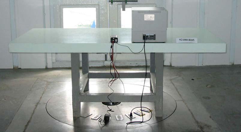
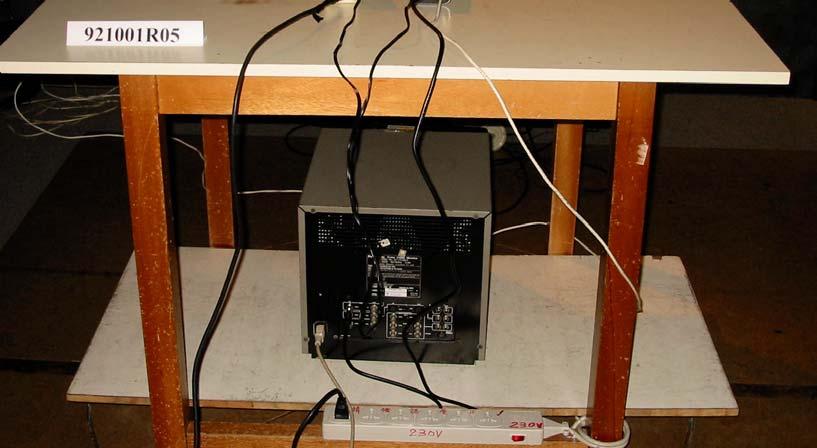
53 6 PHOTOGRAPHS OF THE TEST CONFIGURATION CONDUCTED EMISSION TEST Report No.: CE921001R05 53 Issued: October 27, 2003


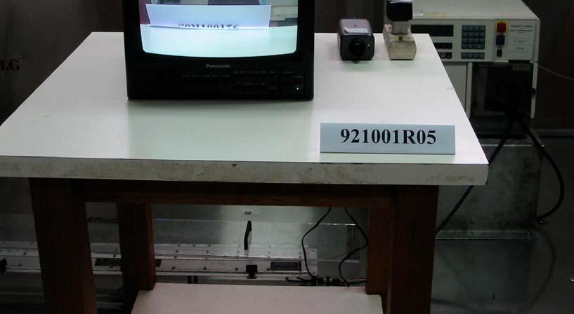
54 RADIATED EMISSION TEST Report No.: CE921001R05 54 Issued: October 27, 2003


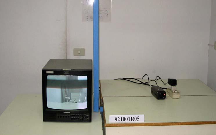
55 HARMONIC and FLICK TEST Report No.: CE921001R05 55 Issued: October 27, 2003


56 ESD TEST 2 Report No.: CE921001R05 56 Issued: October 27, 2003


57 Report No.: CE921001R05 57 Issued: October 27, 2003


58 Report No.: CE921001R05 58 Issued: October 27, 2003


59 RS TEST Report No.: CE921001R05 59 Issued: October 27, 2003
")


60 EFT TEST (RJ45) Report No.: CE921001R05 60 Issued: October 27, 2003


61 (BNC) Report No.: CE921001R05 61 Issued: October 27, 2003


62 SURGE TEST (BNC) Report No.: CE921001R05 62 Issued: October 27, 2003
")


63 CS TEST (CDN-M2) (CON- T4) Report No.: CE921001R05 63 Issued: October 27, 2003

64 (Clamp) Report No.: CE921001R05 64 Issued: October 27, 2003


65 POWER-FREQUENCY MAGNETIC FIELDS TEST VOLTAGE DIPS TEST Report No.: CE921001R05 65 Issued: October 27, 2003
EMC TEST REPORT. Report No.: CE10-LIE040101E
 EMC TEST REPORT Report No.: CE10-LIE040101E Product: LED TUBE Model No.: T10, T8, T5 Applicant: Shenzhen Saiju Electronic Co., Ltd. Address: 2nd. Xianshun Industrial Park, Gushu, Xixiang, Bao an, Shenzhen,
EMC TEST REPORT For MPP SOLAR INC Inverter/ Charger Model Number : PIP 4048HS
 EMC-E20130903E EMC TEST REPORT For MPP SOLAR INC Inverter/ Charger Model Number : PIP 4048HS Prepared for : MPP SOLAR INC Address : 4F, NO. 50-1, SECTION 1, HSIN-SHENG S. RD. TAIPEI, TAIWAN Prepared by
CE EMC TEST REPORT CE940127L06 VIVOTEK INC.
 CE EMC TEST REPORT REPORT NO. : MODEL NO. : CE940127L06 PZ6112, PZ6122, PZ7112, PZ7122, ANC-808V RECEIVED : Jan. 27, 2005 TESTED : Mar. 08 to Apr. 17, 2005 ISSUED : Apr. 18, 2005 APPLICANT : VIVOTEK INC.
EMC TEST REPORT. ADDRESS : #2 Creation Rd. 4, Science-Based Ind. Park Hsinchu Taiwan, R.O.C.
 EMC TEST REPORT REPORT NO. : RM110613E07 MODEL NO. : M-R0027 RECEIVED : June 13, 2011 TESTED : June 17, 2011 ISSUED : June 22, 2011 APPLICANT : LOGITECH FAR EAST LTD. ADDRESS : #2 Creation Rd. 4, Science-Based
FCC TEST REPORT. SendFar Technology Co., Ltd.
 FCC TEST REPORT REPORT NO.: RF921021R02 MODEL NO.: WPC-3110 RECEIVED: October 21, 2003 TESTED: November 14 ~ November 16, 2003 APPLICANT: ADDRESS: SendFar Technology Co., Ltd. 15FL., NO.866-2, JUNGJENG
ITUNER NETWORKS CORPORATION EMC REPORT Fremont Blvd. Fremont, CA
 Shenzhen BST Technology Co., Ltd. ITUNER NETWORKS CORPORATION EMC REPORT Prepared For : ITUNER NETWORKS CORPORATION 47801 Fremont Blvd. Fremont, CA. 94538 Product Name: PicoPSU-150 Trade Name: PicoPSU
FCC TEST REPORT th Lin, Chiapau Tsun, Linko, Taipei, Taiwan, R.O.C. No. 19, Hwa Ya 2 nd Rd., Kueishan, Taoyuan, Taiwan, R.O.C.
 FCC TEST REPORT REPORT NO.: RF941130L05 MODEL NO.: WAP54G ver. 3.1 RECEIVED: Jan. 23, 2006 TESTED: Jan. 23 ~ Feb. 27, 2006 ISSUED: Mar. 02, 2006 APPLICANT: Cisco-Linksys LLC ADDRESS: 121 Theory Drive Irvine,
EMC TEST REPORT. for. Coliy Technology Co.,Ltd. Fluxgate Gaussmeter
 Page 1 of 48 EMC TEST REPORT for Coliy Technology Co.,Ltd. Fluxgate Gaussmeter Prepared for : Coliy Technology Co.,Ltd. Address : Block B,9 th Floor,Xinzhongtai Business Building,Gushu 2nd Road,Xi Town,Bao
APPLICATION FOR EMC DIRECTIVE. On Behalf of. Shenzhen Qinhan Lighting Co., Ltd. led flood light. Trade Name:
 APPLICATION FOR EMC DIRECTIVE On Behalf of Shenzhen Qinhan Lighting Co., Ltd led flood light Trade Name: Model: QH-TGC-400W, QH-TGC-300W, QH-TGC-500W, QH-TGC-800W, QH-TGC-1000W Prepared For : Shenzhen
CE EMC Test Report GUANGZHOU DMKEMOTOR CO. LTD
 CE REPORT CE EMC Test Report Equipment under Test: Model /Type: Applicant: Address: Manufacturer: Address: Laboratory: Address: Report Number Brush D.C. Motor D5D120-24GU D2D10-12GN, D2D10-24GN, D2D10-36GN,
Test Report. Guangdong East Power Co., Ltd. Fully Automatic AC Voltage Regulator. Brand Name:
 Test Report Applicant: Product Name: Brand Name: Model No.: Guangdong East Power Co., Ltd. Fully Automatic AC Voltage Regulator EAST ZTY-30KVA Date of Receipt : Aug. 30, 2013 Date of Test: Sep. 03, 2013
FCC TEST REPORT. LAB ADDRESS: No. 47, 14 th Ling, Chia Pau Tsuen, Linko Hsiang 244, Taipei Hsien, Taiwan, R.O.C.
 FCC TEST REPORT REPORT NO.: RF951204L06A MODEL NO.: WRT54G V8 RECEIVED: Jan. 13, 2007 TESTED: Jan. 13 ~ Jan. 16, 2007 ISSUED: Jan. 17, 2007 APPLICANT: Cisco-Linksys LLC ADDRESS: 121 Theory Drive Irvine,
TEST REPORT... 1 CONTENT...
 CONTENT TEST REPORT... 1 CONTENT... 2 1 TEST RESULTS SUMMARY... 3 2 EMC RESULTS CONCLUSION... 4 3 LABORATORY MEASUREMENTS... 6 4 EMI TEST... 7 4.1 CONTINUOUS CONDUCTED DISTURBANCE VOLTAGE TEST... 7 4.2
1 SUMMARY OF STANDARDS AND RESULTS
 1 SUMMARY OF STANDARDS AND RESULTS 1.1 Description of Standards and Results The EUT have been tested according to the applicable standards as referenced below: EMISSION Description of Test Item Standard
TEST REPORT. Building 6,XinXinTian Industrial Park, XinSha Road, ShaJing, Baoan District, ShenZhen, China
 TEST REPORT Applicant Address Innokin Technology Co.,Ltd Building 6,XinXinTian Industrial Park, XinSha Road, ShaJing, Baoan District, ShenZhen, China Manufacturer or Supplier Address Product Innokin Technology
EMC TEST REPORT. For. Switching Mode Power Adaptor. Model No.: 9W/14.4V/EU(18V/1.0A), 19W/14.4V/EU(12V/1.5A)
, 19W/14.4V/EU(12V/1.5A)") EMC TEST REPORT For Company Limited Liability «Faraday Electronics» Switching Mode Power Adaptor Model No.: 9W/14.4V/EU(18V/1.0A), 19W/14.4V/EU(12V/1.5A) Prepared For : Company Limited Liability «Faraday
EMC TEST REPORT For Company Limited Liability «Faraday Electronics» Switching Mode Power Adaptor Model No.: 9W/14.4V/EU(18V/1.0A), 19W/14.4V/EU(12V/1.5A) Prepared For : Company Limited Liability «Faraday
9. Electrostatic Discharge Immunity Test (ESD)
") 9. Electrostatic Discharge Immunity Test (ESD) Test Mode: Mode 1 Final Test Result : PASS Pass Performance Criteria : A Required Performance Criteria: B Basic Standard : IEC 61000-4-2:Edition 1.2:2001-04
9. Electrostatic Discharge Immunity Test (ESD) Test Mode: Mode 1 Final Test Result : PASS Pass Performance Criteria : A Required Performance Criteria: B Basic Standard : IEC 61000-4-2:Edition 1.2:2001-04
CE EMC Test Certification
 Certification No.: EC57C001 CE EMC Test Certification According to European Standard EN 55022:1998/A1:2000/A2:2003 Class A, EN 61000-3-2: 2000, EN 61000-3-3:1995/A1:2001 and EN 55024:1998/A1:2001/A2:2003
EMC TEST REPORT for SHENZHEN MUST ENERGY TECHNOLOGY CO., LTD
 Page 1 of 45 Report No. R011607240E EMC TEST REPORT for SHENZHEN MUST ENERGY TECHNOLOGY CO., LTD INVERTER CHARGER Model No.: PV35-4K DC24V MPK, PV35-4K DC48V MPK, PV35-5K DC48V MPK, PV35-6K DC48V MPK Prepared
EMC TEST REPORT. According to
 EMC TEST REPORT According to EN 55022:2006/A1:2007 (Class B) EN 55024 : 1998/ A1:2001/ A2:2003 EN 61000-3-2 : 2006/A1:2009/A2:2009 IEC 61000-4-2 : 2008 EN 61000-3-3 : 2008 IEC 61000-4-3 : 2010 IEC 61000-4-4
TEST REPORT. Table of Contents
 Page:2 of 28 Table of Contents 1. DOCUMENT POLICY AND TEST STATEMENT... 3 1.1 DOCUMENT POLICY... 3 1.2 TEST STATEMENT... 3 2. DESCRIPTION OF EUT AND TEST MODE... 4 2.1 GENERAL DESCRIPTION OF EUT... 4 2.2
CE EMC TEST REPORT. LAB LOCATION : No. 81-1, Lu Liao Keng, 9 Ling, Wu Lung Tsuen, Chiung Lin Hsiang, Hsin Chu Hsien, Taiwan
 CE EMC TEST REPORT REPORT NO. : CE951115H04B MODEL NO. : MD15 RECEIVED : Nov. 27, 2006 TESTED : Dec. 04 to 27, 2006 ISSUED: March 07, 2007 APPLICANT : CTC UNION TECHNOLOGIES CO., LTD. ADDRESS : 8F, No.
for Issued for Supremevalue Technology CO., Ltd 4/F,A4 Bldg.,Yinlong Industrial Park,292# Shenshan Rd,518116, Longgang District,Shenzhen,China.
 EMC TEST REPORT for Product: Car Charger Trade Mark: MEKNIC Model: SV-PC01,SV-PC02,SV-PC03,SV-PC04,SV-PC05, SV-PC06,SV-PC07,SV-PC08,SV-PC09,SV-PC10, SV-PC11,SV-PC12,SV-PC13,SV-PC14,SV-PC15, SV-PC16,SV-PC17,SV-PC18,SV-PC19,SV-PC20
ELECTRONICS TESTING CENTER(ETC), TAIWAN
, TAIWAN") File No. : 06-03-RBF-111-01 EMC TESTING DEPARTMENT II Page: 1 / 35 TEST REPORT Responsible Party Manufacturer Description of Product Trade Name : Huan Vu Enterprise Co., Ltd. : Huan Vu Enterprise Co.,
File No. : 06-03-RBF-111-01 EMC TESTING DEPARTMENT II Page: 1 / 35 TEST REPORT Responsible Party Manufacturer Description of Product Trade Name : Huan Vu Enterprise Co., Ltd. : Huan Vu Enterprise Co.,
EMC REPORT. ShenZhen KY Technology Co.,Ltd. No.369, BaoTian 1st RD, TieGang Industrial Park, Xixiang Town, Baoan District, ShenZhen, PRC.
 Report No.: UNI2016121702ER-01 Page 1 / 30 ShenZhen KY Technology Co.,Ltd EMC REPORT Prepared For: ShenZhen KY Technology Co.,Ltd Product Name: Smart bracelet No.369, BaoTian 1st RD, TieGang Industrial
TEST SUMMARY. Prüfbericht - Nr.: Test Report No.: Seite 2 von 25. Page 2 of 25
 15072259 001 Seite 2 von 25 Page 2 of 25 TEST SUMMARY 4.1.1 HARMONICS ON AC MAINS 4.1.2 VOLTAGE FLUCTUATIONS ON AC MAINS 4.1.3 MAINS TERMINAL CONTINUOUS DISTURBANCE VOLTAGE 4.1.4 DISCONTINUOUS INTERFERENCE
TEST REPORT. Building 6, XinXinTian Industrial Park, XinSha Road, ShaJing, Baoan District, ShenZhen, China. Shenzhen Innokin Technology Co.
 TEST REPORT Applicant Address Shenzhen Innokin Technology Co., Ltd Building 6, XinXinTian Industrial Park, XinSha Road, ShaJing, Baoan District, ShenZhen, China Manufacturer or Supplier Address Product
Overview of EMC Regulations and Testing. Prof. Tzong-Lin Wu Department of Electrical Engineering National Taiwan University
 Overview of EMC Regulations and Testing Prof. Tzong-Lin Wu Department of Electrical Engineering National Taiwan University What is EMC Electro-Magnetic Compatibility ( 電磁相容 ) EMC EMI (Interference) Conducted
FCC DoC TEST REPORT. ADDRESS : #2 Creation Rd. 4, Science-Based Ind. Park Hsinchu Taiwan, R.O.C.
 FCC DoC TEST REPORT REPORT NO. : FD990811E03 MODEL NO. : A-E0001 RECEIVED : Aug. 11, 2010 TESTED : Aug. 13 to 17, 2010 ISSUED DATE : Aug. 20, 2010 APPLICANT : LOGITECH FAR EAST LTD. ADDRESS : #2 Creation
EN :2007+A1:2011 Electromagnetic compatibility Emission standard for residential, commercial and light-industrial environments
 EMC Page 3 / 33 Test report No.: EN 61000-6-3:2007+A1:2011 Electromagnetic compatibility Emission standard for residential, commercial and light-industrial environments Date of measurement: 2013-10-16
TEST SUMMARY. Prüfbericht - Nr.: Test Report No.: Seite 2 von 27. Page 2 of 27
 15072768 001 Seite 2 von 27 Page 2 of 27 TEST SUMMARY 4.1.1 HARMONICS ON AC MAINS 4.1.2 VOLTAGE CHANGES, VOLTAGE FLUCTUATIONS AND FLICKER ON AC MAINS 4.1.3 MAINS TERMINAL CONTINUOUS DISTURBANCE VOLTAGE
EN 55022: 2010+AC:2011 Clause 6.1 Pass. Harmonic Current EN :2006+A1:2009+A2:2009 Class A N/A
 Reference No.: WT12106773-N-S-E Page 2 of 33 1 Test Summary Test Item Mains Terminal Disturbance Voltage, 150KHz to 30MHz Radiation Emission, 30MHz to 1000MHz EMISSION Test Standard Class / Severity Result
Test Report GUANGDONG EAST POWER CO., LTD
 Test Report Applicant: Product Name: Brand Name: Model No.: GUANGDONG EAST POWER CO., LTD Online High Frequency UPS EAST EA906IIRTS, EA906IIRTH Date of Receipt : Feb. 26, 2014 Date of Test: Mar. 24, 2014
EMC Test Report For Changzhou Airwheel Technology Co.,Ltd. Airwheel Model: A6S,A6,A6P,A6PS,A6T,A6TS
 EMC Test Report For Changzhou Airwheel Technology Co.,Ltd. Airwheel Model: A6S,A6,A6P,A6PS,A6T,A6TS Prepared For : Prepared By : Changzhou Airwheel Technology Co.,Ltd. Fl.5, East of No. 10 Building, high-tech
CE-EMC TEST REPORT. Prepared for : T&T Assoociates London LTD Suite#306 CityGate House, Bussinedd Centre Stratford, Romford Road, London
 CE-EMC TEST REPORT Prepared for : T&T Assoociates London LTD Suite#306 CityGate House, Bussinedd Centre Stratford, 246-250 Romford Road, London Product: CCTV Camera Trade Name: Model Name: INNOVEXS IPBQH20HH205,
CE TEST CERTIFICATION
 according to Certification No.: E5NC004 European Standard EN 61000-6-4:2001 EN 61000-3-2: 2000, EN 61000-3-3:1995/A1:2001 and EN 61000-6-2:2001 ( IEC 61000-4-2:1995/A1:1998, IEC 61000-4-3: 1995/A1:1998,
FCC DoC TEST REPORT. TESTED : Sep. 01 to 02, 2010 APPLICANT : LOGITECH FAR EAST LTD.
 FCC DoC TEST REPORT REPORT NO. : FD990901E04 MODEL NO. : Y-R0016 RECEIVED : Sep. 01, 2010 TESTED : Sep. 01 to 02, 2010 ISSUED DATE : Sep. 07, 2010 APPLICANT : LOGITECH FAR EAST LTD. ADDRESS : #2 Creation
FCC TEST REPORT (RFID)
") FCC TEST REPORT (RFID) REPORT NO.: RF130923D14-2 MODEL NO.: DC-NU2-UMPC FCC ID: 2AA69001 RECEIVED: Sep. 23, 2013 TESTED: Oct. 11 ~ 17, 2013 ISSUED: Oct. 25, 2013 APPLICANT: Capsule Technologie SAS ADDRESS:
FCC TEST REPORT (RFID) REPORT NO.: RF130923D14-2 MODEL NO.: DC-NU2-UMPC FCC ID: 2AA69001 RECEIVED: Sep. 23, 2013 TESTED: Oct. 11 ~ 17, 2013 ISSUED: Oct. 25, 2013 APPLICANT: Capsule Technologie SAS ADDRESS:
EMC TEST REPORT For. Shenzhen Ruideou Keji Youxian Gongsi. Shenzhen Ruideou Keji Youxian Gongsi
 EMC TEST REPORT For Shenzhen Ruideou Keji Youxian Gongsi Product Name: Trademark: Milligram Scale WAOAW Model Number: W-01-50 Prepared For : Address: Prepared By : Address: Shenzhen Ruideou Keji Youxian
TEST REPORT. Report No. : EM/2008/80003 Page : 1 of 54
 Equipment Under Test Brand Name Model No. Added Model(s) Applicant Address of Applicant Page : 1 of 54 TEST REPORT : AC Servo Motor : Kingservo : AC 400W servo motor : N/A : Ho Fo Automation CO., LTD :
EN 55015: 2013 Clause Pass. EN 55015: 2013 Clause Pass. EN 55015: 2013 Clause Pass
 Reference No.: WTD15S0730643E Page 2 of 42 1 Test Summary Test Item Conducted Disturbance at Mains Terminal, 9kHz to 30MHz Radiation electromagnetic disturbance, 9kHz to 30MHz Radiation Emission, 30MHz
EMC TEST REPORT. according to
 EMC TEST REPORT according to European Standard EN 55022:2006/A1:2007 Class B, EN 61000-3-2:2006, EN 61000-3-3:1995/A1:2001/A2:2006, EN 55024:1998/A1:2001/A2:2003 (IEC 61000-4-2:Edition 1.2:2001-04, IEC
EMC TEST REPORT for LEDELS LIGHTING CO., LTD. LED module Model No. : LL-F12T4815X6B
 Page 1 of 27 Report No. R011412016E-1 EMC TEST REPORT for LEDELS LIGHTING CO., LTD LED module Model No. : LL-F12T4815X6B Prepared for : LEDELS LIGHTING CO., LTD Address : 5F, Block C, Mingjinhai Ind. Park,
TEST REPORT. Table of Contents
 Page:2 of 24 Table of Contents 1. DOCUMENT POLICY AND TEST STATEMENT... 3 1.1 DOCUMENT POLICY...3 1.2 TEST STATEMENT...3 2. DESCRIPTION OF EUT AND TEST MODE... 4 2.1 GENERAL DESCRIPTION OF EUT...4 2.2
PT. SARANA KARYA SOLUSINDO.
 Shenzhen BST Technology Co., Ltd. PT. SARANA KARYA SOLUSINDO. EMC REPORT Prepared For : PT. SARANA KARYA SOLUSINDO. Puri Surya Jaya J1. 29 Cluster Vancouver, Gedangan, Sidoarjo, Jawa Timur - Indonesia
Equipment : AC/DC ADAPTER Test Model No. : ADP-90MD H Applicant : DELTA ELECTRONICS, INC. Test Report No. : CE130910D06
 Equipment : AC/DC ADAPTER Test Model No. : ADP-90MD H Applicant : DELTA ELECTRONICS, INC. Test Report No. : CE130910D06 We, Bureau Veritas Consumer Products Services (H.K.) Ltd., Taoyuan Branch, declare
TEST REPORT. Table of Contents
 Page:2 of 35 Table of Contents 1. DOCUMENT POLICY AND TEST STATEMENT... 4 1.1 DOCUMENT POLICY...4 1.2 TEST STATEMENT...4 1.3 EUT MODIFICATION...4 2. DESCRIPTION OF EUT AND TEST MODE... 5 2.1 GENERAL DESCRIPTION
EMC TEST REPORT For INNOKIN TECHNOLOGY CO., LIMITED. ITaste vv. Model No.: ITaste vv
 EMC TEST REPORT For INNOKIN TECHNOLOGY CO., LIMITED ITaste vv Model No.: ITaste vv Prepared for : INNOKIN TECHNOLOGY CO., LIMITED Address : 3# Floor, #B Building, Heng Chang Rong Industrial Park, Gonghe
TEST SUMMARY Seite 2 von 27. Prüfbericht - Nr.: Test Report No HARMONICS ON AC MAINS RESULT: Passed
 17035561 001 Seite 2 von 27 Page 2 of 27 TEST SUMMARY 5.1.1 HARMONICS ON AC MAINS RESULT: Passed 5.1.2 VOLTAGE FLUCTUATIONS ON AC MAINS RESULT: Passed 5.1.3 TERMINAL CONTINUOUS DISTURBANCE VOLTAGE AT RESULT:
FCC TEST REPORT. ISSUED BY: Bureau Veritas Consumer Products Services (H.K.) Ltd., Taoyuan Branch
 Ltd., Taoyuan Branch") FCC TEST REPORT REPORT NO.: RF971218L04 MODEL NO.: ESR-9753 (Refer to item 3.1 for more detail) RECEIVED: Dec. 18, 2008 TESTED: Dec. 22 ~ Dec. 25, 2008 ISSUED: Dec. 31, 2008 APPLICANT: Senao Networks Inc.
FCC TEST REPORT REPORT NO.: RF971218L04 MODEL NO.: ESR-9753 (Refer to item 3.1 for more detail) RECEIVED: Dec. 18, 2008 TESTED: Dec. 22 ~ Dec. 25, 2008 ISSUED: Dec. 31, 2008 APPLICANT: Senao Networks Inc.
EMC TEST REPORT for : DONGGUAN EVER DEVELOPMENT ELECTRONIC CO., Electronic calculator Model No.: KF15758
 Page 1 of 20 Report No. R011604553E EMC TEST REPORT for DONGGUAN EVER DEVELOPMENT ELECTRONIC CO., LTD. Electronic calculator Model No.: KF15758 Prepared for Address Prepared by Address : DONGGUAN EVER
EMC TEST REPORT. NORTE SIRIUS ENTERPRISE CO., LTD , Shin-Sheng St., Chung-Ho Dist, New Taipei City, Taiwan
 Page 1 of 32 EMC TEST REPORT Report No.: TS11020117-EME Model No.: NS-PSE, NS-POINTED, NS-PSQUARE, NS-PF-S, NS-PT, NS-PR, NS-PU, NS-PF-H, NS-BALIBA, NS-FLEXMA Issued Date: Mar. 01, 2011 Applicant: NORTE
Shenzhen Toby Technology Co., Ltd. EMC Test Report. Report No.: TB-EMC Page: 1 of 20
 Shenzhen Toby Technology Co., Ltd. Report No.: TB-EMC125641 Page: 1 of 20 EMC Test Report Application No. : TB12114299 Applicant : Newmb Technology Co., Ltd. Equipment Under Test (EUT) EUT Name : USB HUB
EMC TEST REPORT. Report No.: TS EME Model No.: 33XR-A Issued Date: Jan. 08, 2009
 Page 1 of 18 EMC TEST REPORT Report No.: TS08100063-EME Model No.: 33XR-A Issued Date: Jan. 08, 2009 Applicant: Test Method/ Standard: Test By: FLUKE CORP. 6920 Seaway Blvd, M/S 266D Everett, WA 98203
EMC TEST REPORT. Report No. : EM/2004/10096 Page : 1 of 19
 EMC TEST REPORT Page : 1 of 19 Equipment Under Test Model No. Applicant Address of Applicant : Bluetooth Headset : FB-HS01 : Formosa Teletek Corporation : 358, Huaya 2 nd Rd., Gueishan shiang, Taoyuan,
2620 Modular Measurement and Control System
 European Union (EU) Council Directive 89/336/EEC Electromagnetic Compatibility (EMC) Test Report 2620 Modular Measurement and Control System Sensoray March 31, 2006 April 4, 2006 Tests Conducted by: ElectroMagnetic
Guangdong East Power Co., Ltd. Uninterruptible Power Systems
 Test Report Applicant: Product Name: Brand Name: Model No.: Guangdong East Power Co., Ltd. Uninterruptible Power Systems EAST EA8806, EA8804 Date of Receipt : Nov. 01, 2012 Date of Test: Nov. 03, 2012
CE TEST CERTIFICATION
 Certification No.: E5DC001 according to European Standard EN 61000-6-4:2001 EN 61000-3-2: 2000, EN 61000-3-3:1995/A1:2001 and EN 61000-6-2:2001 ( IEC 61000-4-2:1995/A1:1998, IEC 61000-4-3: 1995/A1:1998,
CE-EMC TEST REPORT. Test report On Behalf of MAZi Security Systems GmbH For TVI CCTV Camera Model No.: TDE-11S; Serial Model See Page 2
 Page 1 of 55 CE-EMC TEST REPORT Test report On Behalf of MAZi Security Systems GmbH For TVI CCTV Camera Model No.: TDE-11S; Serial Model See Page 2 Prepared for : MAZi Security Systems GmbH Ostwall 216,
TEST REPORT. Product: Thermo-Hygrometer Model No.: FL-201, FL-201W Trade mark: N/A Report No.: TCT151014E001 Issued Date: Oct. 15, 2015.
 TEST REPORT Product: Thermo-Hygrometer Model No.: FL-201, FL-201W Trade mark: N/A Report No.: TCT151014E001 Issued Date: Oct. 15, 2015 Issued for: Shenzhen Flus Technology Co., Ltd 3rd Floor, Lantian Building,
VCCI TEST REPORT. TESTED : June 22 to 23, 2010 APPLICANT : LOGITECH FAR EAST LTD.
 VCCI TEST REPORT REPORT NO. : V990621E07 MODEL NO. : M-U0026 RECEIVED : June 21, 2010 TESTED : June 22 to 23, 2010 ISSUED : June 24, 2010 APPLICANT : LOGITECH FAR EAST LTD. ADDRESS : #2 Creation Rd. 4,
Test Report. Ningbo Goldmore Industrial Co.,Ltd.
 Test Report Applicant: Ningbo Goldmore Industrial Co.,Ltd. Product Name: Brand Name: Model No.: LED CAMPING LANTERN with FAN N/A XJH-8098 Date of Receipt : Sep. 23, 2014 Date of Test: Sep. 25, 2014 Date
CE EMC TEST REPORT. ADDRESS: No. 25, Wu-Gong 6th Rd., Wu Ku Industrial Park, Taipei Hsien, Taiwan, R. O. C.
 CE EMC TEST REPORT REPORT NO.: CE990923D04 MODEL NO.: Y-U0012 RECEIVED: Sep. 23, 2010 TESTED: Sep. 24 ~ 29, 2010 ISSUED: Sep. 30, 2010 APPLICANT: Chicony Electronics Co., Ltd. ADDRESS: No. 25, Wu-Gong
EMC MEASUREMENT AND TEST REPORT
 EN 55014-1:2006/A2:2011, EN 55014-2: 2015 EN 61000-3-2:2014, EN 61000-3-3: 2013 EMC MEASUREMENT AND TEST REPORT FOR Applicant: JINHUA SORIN ELECTRIC VEHICLE CO., LTD Address :NO.518 Meihe Road,Wucheng
SUZHOU MAILI ELECTRICAL APPLIANCE CO., LTD NO.666,JIANLIN RD, XUGUAN SUBAREA, SUZHOU HIGH-TECH ZONE
 EMC TEST REPORT For SUZHOU MAILI ELECTRICAL APPLIANCE CO., LTD Product Name: Pure sine wave power inverter Trademark: Model : Prepared For : Address: Prepared By : Address: ML-1000W ML-300W---ML-8000W.
EMC REPORT DONGGUAN FIT-WATCH CO., LTD. 18#,Hedong No.1 road,jinsha village,changan town, Dongguan City, Guangdong Province.
 DONGGUAN FIT-WATCH CO., LTD. EMC REPORT Prepared For : DONGGUAN FIT-WATCH CO., LTD. 18#,Hedong No.1 road,jinsha village,changan town, Dongguan City, Guangdong Province Product Name : Trade Name : Model
Certificate of Test AND KEEPS ALL REQUIREMENTS ACCORDING THE FOLLOWING REGULATIONS IEC :2001 IEC :2007
 Certificate of Test WE HEREBY CERTIFY THAT: Certificate No.: R07122709E Yuan Hsun Electric Co., Ltd. No. 57, Chung He Rd, Zuo-Ying Dist., Kaohsiung City 813, Taiwan R.O.C. Quad photobeam detector Quad-200CS
Harmonic Current emission EN :2014 Class A Pass. Voltage Fluctuation and Flicker EN :2013 Clause 5 Pass
 Reference No.: WTS15F0323845E Page 2 of 33 1 Test Summary Test Item Mains Terminal Disturbance Voltage, 148.5kHz to 30MHz Disturbance Power, 30MHz to 300MHz Discontinuous Disturbance (Click) Radiated Emission,
CE-EMC TEST REPORT. Prepared for : Kinglumi Co., Ltd. Bldg 3, Nangang 3nd Industrial Zone, Tangtou, Shiyan Town, Bao an District, Shenzhen City, China
 CE-EMC TEST REPORT Prepared for : Kinglumi Co., Ltd. Bldg 3, Nangang 3nd Industrial Zone, Tangtou, Shiyan Town, Bao an District, Shenzhen City, China Product: Trade Name: Model Name: LED Downlight CAMETA
Discontinuous Disturbance (Click) EN :2006+A1:2009+A2:2011 Clause N/A** Radiated Emission, 30MHz to 1000MHz
 EN :2006+A1:2009+A2:2011 Clause N/A** Radiated Emission, 30MHz to 1000MHz") Reference No.: WTN13F0706038E Page 2 of 40 1 Test Summary Test Item Mains Terminal Disturbance Voltage, 148.5kHz to 30MHz Disturbance Power, 30MHz to 300MHz EMISSION Test Standard Class / Severity Result
Reference No.: WTN13F0706038E Page 2 of 40 1 Test Summary Test Item Mains Terminal Disturbance Voltage, 148.5kHz to 30MHz Disturbance Power, 30MHz to 300MHz EMISSION Test Standard Class / Severity Result
Test Report Report No.: G150424B02-03EN Date: May. 07, 2015 Page 1 of 49
 Test Report Report No.: G150424B02-03EN Date: May. 07, 2015 Page 1 of 49 The following information was submitted and identified by/on behalf of the client as: Applicant : Ningbo Shanhuang Electric Appliance
EMC TEST REPORT. For MICRO-STAR INT'L CO.,LTD. USB Card Reader
 EMC TEST REPORT For MICRO-STAR INT'L CO.,LTD USB Card Reader Model : StarReader Prepared For : MICRO-STAR INT'L CO.,LTD No.69, Lide St., Jhonghe City, Taipei County 235, Taiwan Prepared By : Shenzhen Best
CE EMC TEST REPORT. TESTED : June 22 to 23, 2010 APPLICANT : LOGITECH FAR EAST LTD.
 CE EMC TEST REPORT REPORT NO. : CE990621E07 MODEL NO. : M-U0026 RECEIVED : June 21, 2010 TESTED : June 22 to 23, 2010 ISSUED : June 24, 2010 APPLICANT : LOGITECH FAR EAST LTD. ADDRESS : #2 Creation Rd.
TEST REPORT. Table of Contents
 Page:2 of 43 Table of Contents 1. DOCUMENT POLICY AND TEST STATEMENT... 4 1.1 DOCUMENT POLICY... 4 1.2 TEST STATEMENT... 4 2. DESCRIPTION OF EUT AND TEST MODE... 4 2.1 GENERAL DESCRIPTION OF EUT... 4 2.2
EMC Test Report. Report Number: M030826
 Page 1 of 36 EMC Technologies Pty Ltd ABN 82 057 105 549 57 Assembly Drive Tullamarine Victoria Australia 3043 Ph: + 613 9335 3333 Fax: + 613 9338 9260 email: melb@emctech.com.au EMC Test Report Report
TEST REPORT. The submitted sample of the above equipment has been tested for according to the requirements of the following standards:
 TEST REPORT Applicant Address Innokin Technology Co., Ltd Building 6, XinXinTian Industrial Park, XinSha Road, ShaJing, Baoan District, ShenZhen, China Manufacturer or Supplier Address Product Innokin
Discontinuous Disturbance (Click) EN : 2011 Clause Pass Radiated Emission, 30MHz to 1000MHz
 EN : 2011 Clause Pass Radiated Emission, 30MHz to 1000MHz") Reference No.: WTU15U0933879E Page 2 of 45 1 Test Summary Test Item Mains Terminal Disturbance Voltage, 148.5kHz to 30MHz Disturbance Power, 30MHz to 300MHz EMISSION Test Standard Class / Severity Result
Reference No.: WTU15U0933879E Page 2 of 45 1 Test Summary Test Item Mains Terminal Disturbance Voltage, 148.5kHz to 30MHz Disturbance Power, 30MHz to 300MHz EMISSION Test Standard Class / Severity Result
C E R T I F I C A T I O N
 C E R T I F I C A T I O N Applicant Address Manufacturer Address : American Power Conversion Holding Inc. Taiwan Branch : 3F., No. 205, Sec. 3, Beixin Rd., Xindian Dist., New Taipei City 231, Taiwan R.O.C.
EMC TEST REPORT ETSI EN V1.9.2( ) ETSI EN V2.1.1( )
 ETSI EN V2.1.1( )") EMC TEST REPORT ETSI EN 301 489-01 V1.9.2(2011-09) ETSI EN 301 489-17 V2.1.1(2009-05) Product: Bluetooth Mouse Trade Name: N/A Model Name: MBL06 Serial Model: N/A Prepared for GTA Electronics Co., Ltd.
EMC TEST REPORT ETSI EN 301 489-01 V1.9.2(2011-09) ETSI EN 301 489-17 V2.1.1(2009-05) Product: Bluetooth Mouse Trade Name: N/A Model Name: MBL06 Serial Model: N/A Prepared for GTA Electronics Co., Ltd.
APPLICATION FOR CERTIFICATION On Behalf of Futaba Corporation Radio Control Model No.:T10CG-2.4G FCC ID:AZPT10CG-24G Brand : Futaba
 FCC ID. AZPT10CG-24G Page 1 of 56 APPLICATION FOR CERTIFICATION On Behalf of Futaba Corporation Radio Control Model No.:T10CG-2.4G FCC ID:AZPT10CG-24G Brand : Futaba Prepared for : Futaba Corporation 1080
EMC Testing Report. Dual-120CS. Yuan Hsun Electric Co., Ltd.
 EMC Testing Report Equipment Under Test: Model Number: Serial No.: Applicant: Address of Applicant: Multi-Frequency (4 Channel Selectable) Twin Photobeam Detector Dual-120CS Dual-90CS, Dual-60CS, Dual-30CS
Prepared for Address. : KST DIGITAL TECHNOLOGY LIMITED : No.226, Pangu Street, Meixian, Meizhou, Guangdong. Prepared by
 EMC TEST REPORT For KST DIGITAL TECHNOLOGY LIMITED Coreless Servo Model No.: X12-508 Additional Model No.: DS215MG, DS315MG, DS213MG, DS313MG, DS12C, DS12T, X12-306 Prepared for Address : KST DIGITAL TECHNOLOGY
EMC TEST REPORT. For. Soma Medical (Sabah) Sdn Bhd ( D) UVGI AIR STERILIZER. Model No.: SM 20
 Sdn Bhd ( D) UVGI AIR STERILIZER. Model No.: SM 20") EMC TEST REPORT For Soma Medical (Sabah) Sdn Bhd (1248058-D) UVGI AIR STERILIZER Model No.: SM 20 Prepared For : Soma Medical (Sabah) Sdn Bhd (1248058-D) : Block E, Lot 28, 2nd floor, Signature Office,
EMC TEST REPORT For Soma Medical (Sabah) Sdn Bhd (1248058-D) UVGI AIR STERILIZER Model No.: SM 20 Prepared For : Soma Medical (Sabah) Sdn Bhd (1248058-D) : Block E, Lot 28, 2nd floor, Signature Office,
EMC TEST REPORT. For. Boardcon Technology Limited. MINI9G45 Computer on Module. Model No. : MINI9G45
 REPORT NO. PRSZ15110502E EMC TEST REPORT For Boardcon Technology Limited. MINI9G45 Computer on Module Model No. : MINI9G45 Prepared For : Boardcon Technology Limited. : Room 702, Hua Feng Xin An Business
CE EMC TEST REPORT. Model Name: JZH-RF898B JZH-RX898B Report No.: BCTC E. Prepared for
 Shenzhen BCTC Technology Co., Ltd. Report No.: BCTC-160608172-2E CE EMC TEST REPORT Product: Fishing bite alarm Trade Name: Model Name: JZH-RF898B JZH-RX898B Report No.: BCTC-160608172-2E Prepared for
EMC VERIFICATION SUMMARY Report No.: SZHH
 EMC VERIFICATION SUMMARY Toy ITE Others Additional Models: 0801 to 0899 INCLUSIVE, 0804, 0804W, 0805, 0806, 0807, 0808, 0809, 0811, 0811W, 0812, 0813, 0814,0815, 0816, 0817,0817 ROOM 619, 6/F. PENINSULA
CONFORMANCE TEST REPORT FOR EN /-6
 CONFORMANCE TEST REPORT FOR EN 301489-1/-6 Client: Product: Model: Manufacturer/supplier: Aztech Systems Limited DECT Phone H315-S1 (FP) Aztech Systems Limited Date test item received: 2006/05/09 Date
EMC TEST REPORT For DONGHUA ELECTRIC STOCK CO., LTD. OF ZHEJIANG
 EMC TEST REPORT For DONGHUA ELECTRIC STOCK CO., LTD. OF ZHEJIANG SWITCHING POWER SUPPLY Model No. HSM-50-12~48 HSM-15-5~24, HSM-35-12~48. : DONGHUA ELECTRIC STOCK CO., LTD. OF ZHEJIANG : No.3 Tengfei Road,
Test Report. Applicant ASUSTeK COMPUTER INC. 4F, No. 150, Li-Te Rd., Peitou, Taipei, Taiwan. Date of Receipt Jan. 28, Issued Date Mar.
 Test Report Product Name Model No. FCC ID. IC ID. WPC Qi 1.1/1.0 compliance wireless charging micro-usb box Wireless Charger MSQ-ASUSWLCHARGER 3568A-ASWLCHARGER Applicant ASUSTeK COMPUTER INC. Address
EMC standards. Presented by: Karim Loukil & Kaïs Siala
 Training Course on Conformity and Interoperability on Type Approval testing for Mobile Terminals, Homologation Procedures and Market Surveillance, Tunis-Tunisia, from 20 to 24 April 2015 EMC standards
VCCI TEST REPORT. According to. V-3/ , TECHNICAL REQUIREMENTS, Class B ITE. Equipment : USB video camera. Model No. : V-U0017 / V-U0021
 VCCI TEST REPORT According to V-3/2009.04, TECHNICAL REQUIREMENTS, Class B ITE Equipment : USB video camera Model No. : V-U0017 / V-U0021 Applicant : Logitech Far East Ltd. 2 Creation Road IV, Science-Based
CE EMC CERTIFICATION
 according to Certification No.: EC78C004-01 European Standard EN 55022:2006 Class A, EN 61000-3-2:2000, EN 61000-3-3:1995/A1:2001 and EN 55024:1998/A1:2001/A2:2003 ( IEC 61000-4-2:1995/A2:2000, IEC 61000-4-3:2002,
EMC Test Report FATEK AUTOMATION CORP. FATEK. FBs-TBOX N/A
 EMC Test Report Applicant: Address of Applicant: Trade Name: FATEK AUTOMATION CORP. 26FL, NO.29, SEC.2, JUNGJENG E. RD., DANSHUEI DIST., NEW TAIPEI CITY, TAIWAN, R.O.C. FATEK Equipment Under Test: Training
FCC CLASS B COMPLIANCE REPORT (DoC)
") FCC CLASS B COMPLIANCE REPORT (DoC) for Electromagnetic Emissions Of ENTRY LEVEL IP PHONE Trade Name : XONTEL Model Number : XT-19P Serial Number : N/A Report Number : PZD1611741-F Date : Regulations :
FCC CLASS B COMPLIANCE REPORT (DoC) for Electromagnetic Emissions Of ENTRY LEVEL IP PHONE Trade Name : XONTEL Model Number : XT-19P Serial Number : N/A Report Number : PZD1611741-F Date : Regulations :
FCC TEST REPORT (WLAN )
") FCC TEST REPORT (WLAN 15.247) REPORT NO.: RF140220D04 MODEL NO.: LAPAC1750 FCC ID: Q87-LAPAC1750 RECEIVED: Feb. 20, 2014 TESTED: Feb. 20 ~ Mar. 24, 2014 ISSUED: Apr. 14, 2014 APPLICANT: Linksys LLC ADDRESS:
FCC TEST REPORT (WLAN 15.247) REPORT NO.: RF140220D04 MODEL NO.: LAPAC1750 FCC ID: Q87-LAPAC1750 RECEIVED: Feb. 20, 2014 TESTED: Feb. 20 ~ Mar. 24, 2014 ISSUED: Apr. 14, 2014 APPLICANT: Linksys LLC ADDRESS:
FCC TEST REPORT. ADDRESS: #2 Creation Rd. 4, Science-Based Ind. Park Hsinchu Taiwan, R.O.C.
 FCC TEST REPORT REPORT NO.: RF991014E04 MODEL NO.: M-R0018 FCC ID: JNZMR0018 RECEIVED: Oct. 14, 2010 TESTED: Oct. 19, 2010 ISSUED: Oct. 22, 2010 APPLICANT: LOGITECH FAR EAST LTD. ADDRESS: #2 Creation Rd.
CERTIFICATE. Issued Date: Apr. 20, 2006 Report No.: 064L079-IT-US-P01V01
 CERTIFICATE Issued Date: Apr. 20, 2006 Report No.: 064L079-IT-US-P01V01 This is to certify that the following designated product Product : 19 inch Rack-mounted Data Acquisition Computer Trade name : Moxa
CE EMC TEST REPORT. According to
 CE EMC TEST REPORT According to European Standard EN 55022:1998/A1:2000/A2:2003 Class B, EN 61000-3-2:2000, EN 61000-3-3:1995/A1:2001 and EN 55024:1998/A1:2001/A2:2003 ( IEC 61000-4-2:2001, IEC 61000-4-3:2002,
CE EMC Test Report. (Declaration of Conformity) For. Electromagnetic Interference. Prepared for. Eaglerise Electronics (Foshan) Co., Ltd.
 For. Electromagnetic Interference. Prepared for. Eaglerise Electronics (Foshan) Co., Ltd.") Page 1 of 63 CE EMC Test Report (Declaration of Conformity) For Electromagnetic Interference Of Product: LED Power Supply Trade Name: Model Number: EBP012C****CS ( **** is for the output current and represents
Page 1 of 63 CE EMC Test Report (Declaration of Conformity) For Electromagnetic Interference Of Product: LED Power Supply Trade Name: Model Number: EBP012C****CS ( **** is for the output current and represents
EMC COMPLIANCE TEST REPORT
 EMC COMPLIANCE TEST REPORT Technical Statement of Conformity in accordance with the council directive 2004/108/EC The product Equipment Under Test Model Number Product Series Report Number Issue Date Test