CE EMC TEST REPORT. ADDRESS: No. 25, Wu-Gong 6th Rd., Wu Ku Industrial Park, Taipei Hsien, Taiwan, R. O. C.
|
|
|
- Brian Hoover
- 6 years ago
- Views:
Transcription
 Ltd., Taoyuan Branch LAB LOCATION: No.")
1 CE EMC TEST REPORT REPORT NO.: CE990923D04 MODEL NO.: Y-U0012 RECEIVED: Sep. 23, 2010 TESTED: Sep. 24 ~ 29, 2010 ISSUED: Sep. 30, 2010 APPLICANT: Chicony Electronics Co., Ltd. ADDRESS: No. 25, Wu-Gong 6th Rd., Wu Ku Industrial Park, Taipei Hsien, Taiwan, R. O. C. ISSUED BY: Bureau Veritas Consumer Products Services (H.K.) Ltd., Taoyuan Branch LAB LOCATION: No. 47, 14th Ling, Chia Pau Tsuen, Lin Kou Hsiang, Taipei Hsien 244, Taiwan This test report consists of 54 pages in total. It may be duplicated completely for legal use with the approval of the applicant. It should not be reproduced except in full, without the written approval of our laboratory. The client should not use it to claim product certification, approval, or endorsement by TAF, NVLAP, NIST or any government agency. The test results in the report only apply to the tested sample. The test results in this report are traceable to the national or international standards. Report No.: CE990923D04 1 Report Format Version 3.0.3
2 Table of Contents 1 CERTIFICATION SUMMARY OF TEST RESULTS MEASUREMENT UNCERTAINTY GENERAL INFORMATION GENERAL DESCRIPTION OF EUT GENERAL DESCRIPTION OF APPLIED STANDARDS DESCRIPTION OF SUPPORT UNITS FOR EMISSION TEST FOR IMMUNITY TEST EMISSION TEST CONDUCTED EMISSION MEASUREMENT LIMITS OF CONDUCTED EMISSION MEASUREMENT TEST INSTRUMENTS TEST PROCEDURE DEVIATION FROM TEST STANDARD TEST SETUP EUT OPERATING CONDITIONS TEST RESULTS RADIATED EMISSION MEASUREMENT LIMITS OF RADIATED EMISSION MEASUREMENT TEST INSTRUMENTS TEST PROCEDURE DEVIATION FROM TEST STANDARD TEST SETUP EUT OPERATING CONDITIONS TEST RESULTS IMMUNITY TEST GENERAL DESCRIPTION GENERAL DESCRIPTION OF ADDITIONAL TEST GENERAL PERFORMANCE CRITERIA DESCRIPTION PARTICULAR PERFORMANCE CRITERIA DESCRIPTION PARTICULAR PERFORMANCE CRITERIA DESCRIPTION FOR DATA INPUT FUNCTION OF EUT EUT OPERATING CONDITION ELECTROSTATIC DISCHARGE IMMUNITY TEST (ESD) TEST SPECIFICATION TEST INSTRUMENTS TEST PROCEDURE DEVIATION FROM TEST STANDARD TEST SETUP TEST RESULTS RADIATED, RADIO-FREQUENCY, ELECTROMAGNETIC FIELD IMMUNITY TEST (RS)...31 Report No.: CE990923D04 2 Report Format Version 3.0.3
3 5.7.1 TEST SPECIFICATION TEST INSTRUMENTS TEST PROCEDURE DEVIATION FROM TEST STANDARD TEST SETUP TEST RESULTS ELECTRICAL FAST TRANSIENT/BURST IMMUNITY TEST (EFT) TEST SPECIFICATION TEST INSTRUMENTS TEST PROCEDURE DEVIATION FROM TEST STANDARD TEST SETUP TEST RESULTS IMMUNITY TO CONDUCTED DISTURBANCES INDUCED BY RF FIELDS (CS) TEST SPECIFICATION TEST INSTRUMENTS TEST PROCEDURE DEVIATION FROM TEST STANDARD TEST SETUP TEST RESULTS POWER FREQUENCY MAGNETIC FIELD IMMUNITY TEST TEST SPECIFICATION TEST INSTRUMENTS EST PROCEDURE DEVIATION FROM TEST STANDARD TEST SETUP TEST RESULTS PHOTOGRAPHS OF THE TEST CONFIGURATION APPENDIX - INFORMATION ON THE TESTING LABORATORIES...54 Report No.: CE990923D04 3 Report Format Version 3.0.3
4 1 CERTIFICATION PRODUCT: Logitech Media Keyboard K200 BRAND NAME: Logitech, Logicool MODEL NO: Y-U0012 TEST ITEM: ENGINEERING SAMPLE APPLICANT: Chicony Electronics Co., Ltd. TESTED: Sep. 24 ~ 29, 2010 STANDARDS: EN 55022: 2006+A1: 2007, Class B CISPR 22: 2005+A1: 2005, Class B AS/NZS CISPR 22: 2006, Class B EN 55024: 1998+A1: 2001+A2: 2003 IEC : 2008 ED.2.0 IEC : 2008 ED.3.1 IEC : 2004+A1: 2010 ED.2.0 IEC : 2005 ED.2.0 (Not Applicable) IEC : 2008 ED.3.0 IEC : 2009 ED.2.0 IEC : 2004 ED.2.0 (Not Applicable) The above equipment has been tested by Bureau Veritas Consumer Products Services (H.K.) Ltd., Taoyuan Branch, and found compliance with the requirement of the above standards. Approval signature on next page Report No.: CE990923D04 4 Report Format Version 3.0.3
5 CERTIFICATION - Continued The test record, data evaluation & Equipment Under Test (EUT) configurations represented herein are true and accurate accounts of the measurements of the sample s EMC characteristics under the conditions specified in this report. PREPARED BY :, DATE: Sep. 30, 2010 ( Celia Chen / Senior Specialist ) TECHNICAL ACCEPTANCE :, DATE: Sep. 30, 2010 Responsible for EMI ( Arthur Lin / Supervisor ) TECHNICAL ACCEPTANCE :, DATE: Sep. 30, 2010 Responsible for EMS ( Joyce Chen / Supervisor ) APPROVED BY :, DATE: Sep. 30, 2010 ( Kenny Meng / Assistant Manager ) Report No.: CE990923D04 5 Report Format Version 3.0.3
6 2 SUMMARY OF TEST RESULTS The EUT has been tested according to the following specifications: EMISSION Standard Test Type Result Remarks EN 55022: A1: 2007, Class B CISPR 22: A1: 2005, Class B AS/NZS CISPR 22: 2006, Class B Conducted Test Radiated Test (30MHz ~ 1GHz) PASS PASS Meets Class B Limit Minimum passing margin is db at MHz Meets Class B Limit Minimum passing margin is 6.75 db at MHz Note: The EUT highest frequency generated below 108MHz and therefore the test frequency range was performed for 30MHz to 1GHz for radiated emission test. IMMUNITY (EN 55024: 1998+A1: 2001+A2: 2003) Standard Test Type Result Remarks IEC : 2008 ED.2.0 IEC : 2008 ED.3.1 IEC : A1: 2010 ED.2.0 IEC : 2005 ED.2.0 IEC : 2008 ED.3.0 IEC : 2009 ED.2.0 IEC : 2004 ED.2.0 Electrostatic discharge immunity test Radiated, radio-frequency, electromagnetic field immunity test Electrical fast transient / burst immunity test. PASS PASS PASS Meets the requirements of Performance Criterion A Meets the requirements of Performance Criterion A Meets the requirements of Performance Criterion A Surge immunity test N/A Please refer to item 3.2 Immunity to conducted disturbances, induced by radio-frequency fields Power frequency magnetic field immunity test. Voltage dips, short interruptions and voltage variations immunity tests PASS PASS Meets the requirements of Performance Criterion A Meets the requirements of Performance Criterion A N/A Please refer to item 3.2 Report No.: CE990923D04 6 Report Format Version 3.0.3
7 2.1 MEASUREMENT UNCERTAINTY Where relevant, the following measurement uncertainty levels have been estimated for tests performed on the EUT as specified in CISPR This uncertainty represents an expanded uncertainty expressed at approximately the 95% confidence level using a coverage factor of k=2. MEASUREMENT Conducted emissions Radiated emissions UNCERTAINTY 3.43 db 3.68 db Report No.: CE990923D04 7 Report Format Version 3.0.3
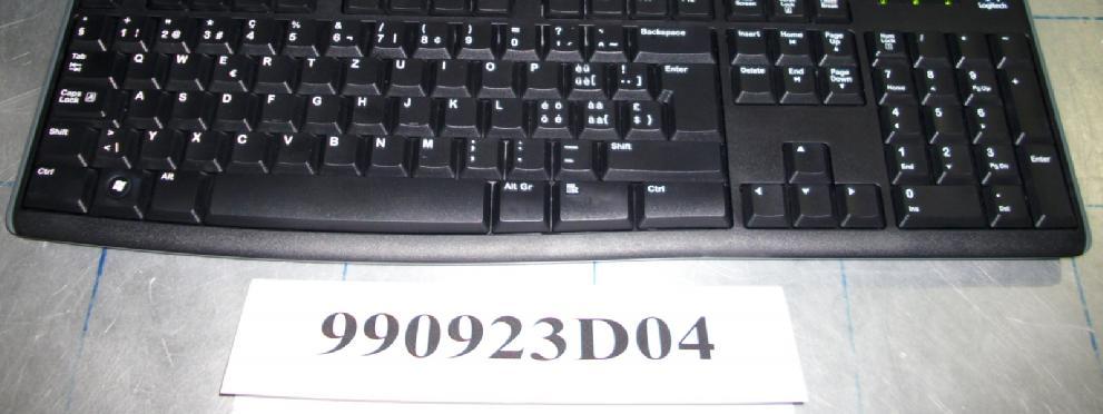
8 3 GENERAL INFORMATION 3.1 GENERAL DESCRIPTION OF EUT PRODUCT MODEL NO. POWER SUPPLY DATA CABLE SUPPLIED Logitech Media Keyboard K200 Y-U0012 DC 5V from PC Shielded USB cable (1.8m). NOTE: 1. The EUT is a Logitech Media Keyboard K200 with USB interface. 2. The EUT consumed power from PC, which designed with AC power supply of Vac, 50/60Hz. For radiated emission evaluation, 230Vac/ 50Hz (for EN 55022), 120Vac/ 60Hz (for FCC Part 15), 110Vac/ 60Hz (for BSMI CNS 13438) & 100Vac/50Hz (for VCCI) had been covered during the pre-test. The worst radiated emission data was founded at 110Vac/ 60Hz and recorded in the applied test report. 3. For a more detailed features description, please refer to the manufacturer's specifications or the User's Manual. Report No.: CE990923D04 8 Report Format Version 3.0.3
9 3.2 GENERAL DESCRIPTION OF APPLIED STANDARDS The EUT is a kind of ITE equipment and, according to the specifications of the manufacturers, must comply with the requirements of the following standards: EN 55022: 2006+A1: 2007, Class B CISPR 22: 2005+A1: 2005, Class B AS/NZS CISPR 22: 2006, Class B EN 55024: 1998+A1: 2001+A2: 2003 IEC : 2008 ED.2.0 IEC : 2008 ED.3.1 IEC : 2004+A1: 2010 ED.2.0 IEC : 2008 ED.3.0 IEC : 2009 ED.2.0 The EUT doesn t connect directly to the outdoor cables and consumes DC power. Therefore the standard, IEC was not tested. The EUT consumes DC power and therefore, the standard, IEC , was not tested. Notes: The above IEC basic standards are applied with latest version if customer has no special requirement. Report No.: CE990923D04 9 Report Format Version 3.0.3
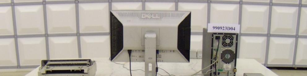
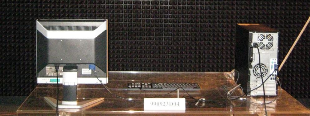
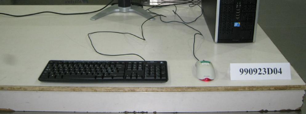
10 3.3 DESCRIPTION OF SUPPORT UNITS The EUT has been tested as an independent unit together with other necessary accessories or support units. The following support units or accessories were used to form a representative test configuration during the tests FOR EMISSION TEST NO. PRODUCT BRAND MODEL NO. SERIAL NO. FCC ID 1 PC HP DX-7400MT SGH8360B8W FCC DoC Approved 2 WIDESCREEN FLAT PANEL MONITOR DELL 2408WFP CN0G293H7426 FCC DoC Approved S 3 PRINTER EPSON LQ-300+II G88Y FCC DoC Approved 4 MODEM ACEEX IFAXDM PS/2 MOUSE BTC M851 M E5XMSM860 6 SPEAKER KINYO KSP-25 S N/A NO. 1 N/A SIGNAL CABLE DESCRIPTION OF THE ABOVE SUPPORT UNITS 1.8 m braid shielded wire, terminated with VGA connector via metallic frame, with two cores 1.8m braid shielded wire, terminated with DB25 and Centronics connector via metallic frame, w/o core 1.2 m braid shielded wire, terminated with DB25 and DB9 connector via metallic frame, w/o core m Non shielded wire, terminated with PS/2 connector via drain wire, w/o core. 1.0 m wrapped shielded wire, terminated via drain wire, with 3.5 mm phone plug, w/o 6 core NOTE: All power cords of the above support units are non-shielded (1.8m). TEST CONFIGURATION Modem PC Monitor Printer Shielded USB cable (1.8 m) Speaker EUT PS/2 Mouse Report No.: CE990923D04 10 Report Format Version 3.0.3
11 3.3.2 FOR IMMUNITY TEST NO. PRODUCT BRAND MODEL NO. SERIAL NO. FCC ID 1 PERSONAL COMPUTER HP 6000ProMT SGH947Q25S FCC DoC Approved 2 COLOR AU4A PHILIPS HNB7107T MONITOR 94 FCC DoC Approved 3 USB MOUSE MICROSOFT X FCC DoC Approved NO. SIGNAL CABLE DESCRIPTION OF THE ABOVE SUPPORT UNITS 1 N/A 1.8 m braid shielded wire, terminated with VGA connector via metallic frame, with two 2 cores & 1.8 m Audio cable m foil shielded wire, terminated with USB connector via drain wire, with 1 core. NOTE: All power cords of the above support units are non-shielded (1.8m). TEST CONFIGURATION Audio cable PC Monitor Shielded USB cable (1.8m) EUT USB Mouse Report No.: CE990923D04 11 Report Format Version 3.0.3
12 4 EMISSION TEST 4.1 CONDUCTED EMISSION MEASUREMENT LIMITS OF CONDUCTED EMISSION MEASUREMENT TEST STANDARD: EN FREQUENCY (MHz) Class A (dbuv) Class B (dbuv) Quasi-peak Average Quasi-peak Average NOTE: (1) The lower limit shall apply at the transition frequencies. (2) The limit decreases in line with the logarithm of the frequency in the range of 0.15 to 0.50 MHz. (3) All emanations from a class A/B digital device or system, including any network of conductors and apparatus connected thereto, shall not exceed the level of field strengths specified above. Report No.: CE990923D04 12 Report Format Version 3.0.3
13 4.1.2 TEST INSTRUMENTS DESCRIPTION & CALIBRATED CALIBRATED MODEL NO. SERIAL NO. MANUFACTURER DATE UNTIL ROHDE & SCHWARZ Test ESCS Dec. 07, 2009 Dec. 06, 2010 Receiver ROHDE & SCHWARZ Artificial Mains Network ESH3-Z /001 Feb. 10, 2010 Feb. 09, 2011 (for EUT) LISN With Adapter (for EUT) AD10 C09Ada-001 Feb. 10, 2010 Feb. 09, 2011 ROHDE & SCHWARZ Artificial Mains Network ESH2-Z Dec. 08, 2009 Dec. 07, 2010 (for EUT) ROHDE & SCHWARZ Artificial Mains Network ESH3-Z /002 Mar. 16, 2010 Mar. 15, 2011 (for peripherals) ROHDE & SCHWARZ Artificial Mains Network ESH3-Z Nov. 06, 2009 Nov. 05, 2010 (for peripherals) Software ADT_Cond_V7.3.7 NA NA NA Software ADT_ISN_V7.3.7 NA NA NA RF cable (JYEBAO) 5D-FB Cable-C09.01 Feb. 25, 2010 Feb. 24, 2011 SUHNER Terminator (For ROHDE & SCHWARZ LISN) 65BNC-5001 E May 27, 2010 May 26, 2011 NOTE: 1. The calibration interval of the above test instruments is 12 months and the calibrations are traceable to NML/ROC and NIST/USA. 2. The test was performed in Shielded Room No The VCCI Site Registration No. C Report No.: CE990923D04 13 Report Format Version 3.0.3
14 4.1.3 TEST PROCEDURE a. The EUT was placed 0.4 meters from the conducting wall of the shielded room with EUT being connected to the power mains through a line impedance stabilization network (LISN). Other support units were connected to the power mains through another LISN. The two LISNs provide 50 Ohm/ 50uH of coupling impedance for the measuring instrument. b. Both lines of the power mains connected to the EUT were checked for maximum conducted interference. c. The frequency range from 150 khz to 30 MHz was searched. Emission levels under (Limit - 20dB) were not recorded DEVIATION FROM TEST STANDARD No deviation Report No.: CE990923D04 14 Report Format Version 3.0.3
15 4.1.5 TEST SETUP Vertical Ground Reference Plane Test Receiver 40cm EUT 80cm LISN Horizontal Ground Reference Plane Note: 1.Support units were connected to second LISN. 2.Both of LISNs (AMN) are 80 cm from EUT and at least 80 cm from other units and other metal planes For the actual test configuration, please refer to the related item Photographs of the Test Configuration EUT OPERATING CONDITIONS a. Turned on the power of all equipment. b. PC ran a test program to enable all functions. c. PC read and wrote messages from HDD. d. EUT sent "H" character to PC. e. PC sent "H" messages to monitor, and then the monitor displayed them on its screen. f. PC sent messages to printer, and then printer printed it out. g. PC sent messages to modem. h. PC sent 1kHz audio signal to speakers. i. Repeated steps c-i. Report No.: CE990923D04 15 Report Format Version 3.0.3
16 4.1.7 TEST RESULTS TEST MODE Operating 6dB BANDWIDTH 9 khz NPUT POWER (SYSTEM) ENVIRONMENTAL CONDITIONS 230Vac, 50 Hz PHASE Line (L) 26deg. C, 74% RH, 1011hPa TESTED BY: ED. Lin Freq. Corr. Reading Value Emission Level Limit Margin No Factor [db (uv)] [db (uv)] [db (uv)] (db) [MHz] (db) Q.P. AV. Q.P. AV. Q.P. AV. Q.P. AV REMARKS: 1. Q.P. and AV. are abbreviations of quasi-peak and average individually. 2. "-": The Quasi-peak reading value also meets average limit and measurement with the average detector is unnecessary. 3. The emission levels of other frequencies were very low against the limit. 4. Margin value = Emission level - Limit value 5. Correction factor = Insertion loss + Cable loss 6. Emission Level = Correction Factor + Reading Value. Report No.: CE990923D04 16 Report Format Version 3.0.3
] [db (uv)] [db (uv)] (db) [MHz] (db) Q.P. AV. Q.P. AV. Q.P. AV. Q.P. AV. 1 0.158 0.17 34.28-34.45-65.58 55.58-31.13-2 0.213 0.17 43.23-43.")
17 TEST MODE Operating 6dB BANDWIDTH 9 khz NPUT POWER (SYSTEM) ENVIRONMENTAL CONDITIONS 230Vac, 50 Hz PHASE Neutral (N) 26deg. C, 74% RH, 1011hPa TESTED BY: ED. Lin Freq. Corr. Reading Value Emission Level Limit Margin No Factor [db (uv)] [db (uv)] [db (uv)] (db) [MHz] (db) Q.P. AV. Q.P. AV. Q.P. AV. Q.P. AV REMARKS: 1. Q.P. and AV. are abbreviations of quasi-peak and average individually. 2. "-": The Quasi-peak reading value also meets average limit and measurement with the average detector is unnecessary. 3. The emission levels of other frequencies were very low against the limit. 4. Margin value = Emission level - Limit value 5. Correction factor = Insertion loss + Cable loss 6. Emission Level = Correction Factor + Reading Value. Report No.: CE990923D04 17 Report Format Version 3.0.3
18 4.2 RADIATED EMISSION MEASUREMENT LIMITS OF RADIATED EMISSION MEASUREMENT TEST STANDARD: EN FOR FREQUENCY BELOW 1000 MHz FREQUENCY Class A (at 10m) Class B (at 10m) (MHz) dbuv/m dbuv/m FOR FREQUENCY ABOVE 1000 MHz FREQUENCY (GHz) Class A (dbuv/m) (at 3m) Class B (dbuv/m) (at 3m) PEAK AVERAGE PEAK AVERAGE 1 to to NOTE: (1) The lower limit shall apply at the transition frequencies. (2) Emission level (dbuv/m) = 20 log Emission level (uv/m). (3) All emanation from a class A/B digital device or system, including any network of conductors and apparatus connected thereto, shall not exceed the level of field strengths specified above. FREQUENCY RANGE OF RADIATED MEASUREMENT (For unintentional radiators) Highest frequency generated or Upper frequency of measurement used in the device or on which the device operates or tunes (MHz) Range (MHz) Below Up to 5 times of the highest Above 1000 frequency or 6 GHz, whichever is less Report No.: CE990923D04 18 Report Format Version 3.0.3
19 4.2.2 TEST INSTRUMENTS DESCRIPTION & CALIBRATED CALIBRATED MODEL NO. SERIAL NO. MANUFACTURER DATE UNTIL Agilent Preamplifier 8447D 2944A11062 Sep. 02, 2010 Sep. 01, 2011 Agilent Preamplifier 8447D 2944A11064 Sep. 02, 2010 Sep. 01, 2011 Agilent Test Spectrum E4443A MY Aug. 02, 2010 Aug. 01, 2011 Agilent Test Spectrum E4443A MY Jul. 28, 2010 Jul. 27, 2011 Agilent Test Preselector N9039A MY Aug. 02, 2010 Aug. 01, 2011 Agilent Test Preselector N9039A MY Jul. 28, 2010 Jul. 27, 2011 Agilent Signal Generator N5181A MY Jul. 28, 2010 Jul. 27, 2011 Schwarzbeck Antenna VULB Apr. 30, 2010 Apr. 29, 2011 Schwarzbeck Antenna VULB Apr. 30, 2010 Apr. 29, 2011 Max Full. Turn Table & Tower MF7802 MF NA NA Max Full. Tower MF7802 MF NA NA Software WOKEN RF cable JYE BAO RF cable JYE BAO RF cable ADT_Radiated_V D 8D 8D NA NA NA CABLE-CH8-01.V CABLE-CH8-02.H CABLE-CH8-03.3M Dec. 23, 2009 Dec. 22, 2010 Dec. 23, 2009 Dec. 22, 2010 Dec. 23, 2009 Dec. 22, 2010 NOTE: 1. The calibration interval of the above test instruments is 12 months. And the calibrations are traceable to NML/ROC and NIST/USA. 2. The test was performed in Chamber No The Industry Canada Reference No. IC 7450E The VCCI Site Registration No. R The FCC Site Registration No Report No.: CE990923D04 19 Report Format Version 3.0.3
20 4.2.3 TEST PROCEDURE a. The EUT was placed on the top of a rotating table 0.8 meters above the ground at a 10 meter Semi-anechoic chamber room. The table was rotated 360 degrees to determine the position of the highest radiation. b. The EUT was set 10 meters away from the interference-receiving antenna, which was mounted on the top of a variable-height antenna tower. c. The height of antenna is varied from one meter to four meters above the ground to determine the maximum value of the field strength. Both horizontal and vertical polarizations of the antenna are set to make the measurement. d. For each suspected emission, the EUT was arranged to its worst case and then the antenna was tuned to heights from 1 meter to 4 meters and the turn table was turned from 0 degrees to 360 degrees to find the maximum reading. e. The test-receiver system was set to quasi-peak detect function and specified bandwidth with maximum hold mode when the test frequency is below 1 GHz. NOTE: The resolution bandwidth of test receiver/spectrum analyzer is 120kHz for Quasi-peak detection (QP) at frequency below 1GHz DEVIATION FROM TEST STANDARD No deviation Report No.: CE990923D04 20 Report Format Version 3.0.3
21 4.2.5 TEST SETUP EUT& Support Units 10m Ant. Tower 1-4m Variable Turn Table 80cm Ground Plane Test Receiver For the actual test configuration, please refer to the related item Photographs of the Test Configuration EUT OPERATING CONDITIONS Same as item Report No.: CE990923D04 21 Report Format Version 3.0.3

22 4.2.7 TEST RESULTS TEST MODE FREQUENCY RANGE ENVIRONMENTAL CONDITIONS Operating MHz 25deg. C, 68% RH, 1011hPa DETECTOR FUNCTION & BANDWIDTH TESTED BY: ED. Lin Quasi-Peak, 120kHz No. ANTENNA POLARITY & TEST DISTANCE: HORIZONTAL AT 10 M Freq. (MHz) Emission Level (dbuv/m) Limit (dbuv/m) Margin (db) Antenna Height (m) Table Angle (Degree) Raw Value (dbuv) Correction Factor (db/m) QP H QP H QP H QP H QP H QP H REMARKS: 1. Emission level(dbuv/m)=raw Value(dBuV) + Correction Factor(dB/m) 2. Correction Factor(dB/m) = Antenna Factor (db/m) + Cable Factor (db) 3. The other emission levels were very low against the limit. 4. Margin value = Emission level Limit value. Report No.: CE990923D04 22 Report Format Version 3.0.3
23 TEST MODE FREQUENCY RANGE ENVIRONMENTAL CONDITIONS Operating MHz 25deg. C, 68% RH, 1011hPa DETECTOR FUNCTION & BANDWIDTH TESTED BY: ED. Lin Quasi-Peak, 120kHz No. ANTENNA POLARITY & TEST DISTANCE: VERTICAL AT 10 M Freq. (MHz) Emission Level (dbuv/m) Limit (dbuv/m) Margin (db) Antenna Height (m) Table Angle (Degree) Raw Value (dbuv) Correction Factor (db/m) QP V QP V QP V QP V QP V QP V QP V REMARKS: 1. Emission level(dbuv/m)=raw Value(dBuV) + Correction Factor(dB/m) 2. Correction Factor(dB/m) = Antenna Factor (db/m) + Cable Factor (db) 3. The other emission levels were very low against the limit. 4. Margin value = Emission level Limit value. Report No.: CE990923D04 23 Report Format Version 3.0.3
24 5 IMMUNITY TEST 5.1 GENERAL DESCRIPTION Product Standard: EN 55024: 1998+A1: 2001+A2: 2003 Basic Standard, specification requirement, and Performance Criteria: IEC Electrostatic Discharge ESD: 8kV air discharge, 4kV Contact discharge, Performance Criterion B IEC Radio-Frequency Electromagnetic Field Susceptibility Test RS: MHz, 3V/m, 80% AM (1kHz), Performance Criterion A IEC Electrical Fast Transient/Burst - EFT AC Power line: 1kV, DC Power line: 0.5kV Signal line: 0.5kV Performance Criterion B IEC Conducted Radio Frequency Disturbances Test CS: MHz, 3Vrms, 80% AM, 1kHz, Performance Criterion A IEC Power Frequency Magnetic Field Test, 50 Hz, 1A/m, Performance Criterion A 5.2 GENERAL DESCRIPTION OF ADDITIONAL TEST Basic Standard, specification requirement, and Performance Criteria: IEC Electrostatic Discharge ESD: 12kV air discharge, 6kV Contact discharge, Performance Criterion B IEC Radio-Frequency Electromagnetic Field Susceptibility Test RS: MHz, 3V/m, 80% AM (1kHz) Performance Criterion A IEC Electrical Fast Transient/Burst - EFT AC Power line: 1.2kV Performance Criterion B Report No.: CE990923D04 24 Report Format Version 3.0.3
25 5.3 GENERAL PERFORMANCE CRITERIA DESCRIPTION According to Clause 7.1 of EN 55024: 1998+A1: A2: 2003 standard, the following describes the general performance criteria. CRITERION A CRITERION B CRITERION C The equipment shall continue to operate as intended without operator intervention. No degradation of performance or loss of function is allowed below a performance level specified by the manufacturer when the equipment is used as intended. The performance level may be replaced by a permissible loss of performance. If the minimum performance level or the permissible performance loss is not specified by the manufacturer, then either of these may be derived from the product description and documentation, and by what the user may reasonably expect from the equipment if used as intended. After the test, the equipment shall continue to operate as intended without operator intervention. No degradation of performance or loss of function is allowed, after the application of the phenomenon below a performance level specified by the manufacturer, when the equipment is used as intended. The performance level may be replaced by a permissible loss of performance. During the test, degradation of performance is allowed. However, no change of operating state if stored data is allowed to persist after the test. If the minimum performance level (or the permissible performance loss) is not specified by the manufacturer, then either of these may be derived from the product description and documentation, and by what the user may reasonably expect from the equipment if used as intended. Loss of function is allowed, provided the function is self-recoverable, or can be restored by the operation of the controls by the user in accordance with the manufacturer s instructions. Functions, and/or information stored in non-volatile memory, or protected by a battery backup, shall not be lost. Report No.: CE990923D04 25 Report Format Version 3.0.3
26 5.4 PARTICULAR PERFORMANCE CRITERIA DESCRIPTION PARTICULAR PERFORMANCE CRITERIA DESCRIPTION FOR DATA INPUT FUNCTION OF EUT CRITERION A CRITERION B CRITERION C Unintended input from input device is not allowed. Input devices shall maintain the specified quality image data. Lock up is not allowed. For equipment with manually inputted data which can be confirmed by reading the display, errors which can be recognized by the operator and easily corrected are permissible. Failures resulting in a delay in processing after the external disturbance is removed, but which can be recovered to normal operation by reset or reboot are permissible. Failures resulting in a system abort, which can be recovered to normal operation by reset or reboot, are permissible. 5.5 EUT OPERATING CONDITION a. Turned on the power of all equipment. b. PC ran a test program to enable all functions. c. EUT sent "H" character to PC. d. PC sent "H" messages to monitor, and then the monitor displayed them on its screen. e. PC sent audio signal to int. speaker of monitor. f. Repeated steps c-f. Report No.: CE990923D04 26 Report Format Version 3.0.3
27 5.6 ELECTROSTATIC DISCHARGE IMMUNITY TEST (ESD) TEST SPECIFICATION Basic Standard: IEC Discharge Impedance: 330 ohm / 150 pf Discharge Voltage: Air Discharge : 2, 4, 8, 12kV (Direct) Contact Discharge : 2, 4, 6kV (Direct & Indirect) Polarity: Positive & Negative Number of Discharge: Air Discharge: min. 20 times at each test point Contact Discharge: min. 200 times in total Discharge Mode: Single Discharge Discharge Period: 1 second minimum TEST INSTRUMENTS DESCRIPTION & MANUFACTURER EM Test ESD Simulator MODEL NO. SERIAL NO. CALIBRATED DATE CALIBRATED UNTIL Dito V Mar. 29, 2010 Mar. 28, 2011 NOTE: 1. The test was performed in ESD Room No The calibration interval of the above test instruments is 12 months and the calibrations are traceable to NML/ROC and NIST/USA TEST PROCEDURE The discharges shall be applied in two ways: a. Contact discharges to the conductive surfaces and coupling planes: The EUT shall be exposed to at least 200 discharges, 100 each at negative and positive polarity, at a minimum of four test points. One of the test points shall be subjected to at least 50 indirect discharges to the center of the front edge of the horizontal coupling plane. The remaining three test points shall each receive at least 50 direct contact discharges. If no direct contact test points are available, then at least 200 indirect discharges shall be applied in the indirect mode. Test shall be performed at a maximum repetition rate of one discharge per second. b. Air discharges at slots and apertures and insulating surfaces: On those parts of the EUT where it is not possible to perform contact discharge testing, the equipment should be investigated to identify user accessible points where breakdown may occur. Such points are tested using the air discharge method. This investigation should be restricted to those area normally handled by the user. A minimum of 10 single air discharges shall be applied to the selected test point for each such area. Report No.: CE990923D04 27 Report Format Version 3.0.3
28 The basic test procedure was in accordance with IEC : a. Electrostatic discharges were applied only to those points and surfaces of the EUT that are accessible to users during normal operation. b. The test was performed with at least ten single discharges on the pre-selected points in the most sensitive polarity. c. The time interval between two successive single discharges was at least 1 second. d. The ESD generator was held perpendicularly to the surface to which the discharge was applied and the return cable was at least 0.2 meters from the EUT. e. Contact discharges were applied to the non-insulating coating, with the pointed tip of the generator penetrating the coating and contacting the conducting substrate. f. Air discharges were applied with the round discharge tip of the discharge electrode approaching the EUT as fast as possible (without causing mechanical damage) to touch the EUT. After each discharge, the ESD generator was removed from the EUT and re-triggered for a new single discharge. The test was repeated until all discharges were complete. g. At least ten single discharges (in the most sensitive polarity) were applied to the Horizontal Coupling Plane at points on each side of the EUT. The ESD generator was positioned horizontally at a distance of 0.1 meters from the EUT with the discharge electrode touching the HCP. h. At least ten single discharges (in the most sensitive polarity) were applied to the center of one vertical edge of the Vertical Coupling Plane in sufficiently different positions that the four faces of the EUT were completely illuminated. The VCP (dimensions 0.5m x 0.5m) was placed vertically to and 0.1 meters from the EUT DEVIATION FROM TEST STANDARD The requirement was followed by client s specification (refer to item 5.2). Report No.: CE990923D04 28 Report Format Version 3.0.3
29 5.6.5 TEST SETUP >1m 0.1m Vertical coupling plane ESD Generator EUT 0.5mm Isolation Support Nearest Wall Horizontal coupling plane 80cm 470k x4 PS Ground Reference Plane For the actual test configuration, please refer to the related item Photographs of the Test Configuration. NOTE: TABLE-TOP EQUIPMENT The configuration consisted of a wooden table 0.8 meters high standing on the Ground Reference Plane. The GRP consisted of a sheet of aluminum at least 0.25mm thick, and 2.5 meters square connected to the protective grounding system. A Horizontal Coupling Plane (1.6m x 0.8m) was placed on the table and attached to the GRP by means of a cable with 940kΩ total impedance. The equipment under test, was installed in a representative system as described in section 7 of IEC , and its cables were placed on the HCP and isolated by an insulating support of 0.5mm thickness. A distance of 1-meter minimum was provided between the EUT and the walls of the laboratory and any other metallic structure. FLOOR-STANDING EQUIPMENT The equipment under test was installed in a representative system as described in section 7 of IEC , and its cables were isolated from the Ground Reference Plane by an insulating support of 0.1-meter thickness. The GRP consisted of a sheet of aluminum that is at least 0.25mm thick, and 2.5 meters square connected to the protective grounding system and extended at least 0.5 meters from the EUT on all sides. Report No.: CE990923D04 29 Report Format Version 3.0.3
30 5.6.6 TEST RESULTS INPUT POWER (SYSTEM) ENVIRONMENTAL CONDITIONS 230Vac, 50 Hz 26deg. C, 43% RH, 1011hPa TESTED BY: Thomas Cheng Discharge Level (kv) TEST RESULTS OF DIRECT APPLICATION Polarity Test Point Contact Discharge Air Discharge Performance Criterion 2, 4, 6 +/- 1, 6 Note N/A A 2, 4, 8, 12 +/- 1 ~ 6 N/A Note A Description of test point: Please refer to ESD test photo for representative mark only. Discharge Level (kv) TEST RESULTS OF INDIRECT APPLICATION Horizontal Vertical Polarity Test Point Coupling Coupling Plane Plane Performance Criterion 2, 4, 6 +/- 1 ~ 4 Note Note A Description of test point: 1. Left side 2. Right side 3. Front side 4. Rear side NOTE: There was no change compared with the initial operation during the test. (2) The LED indicator of EUT was flickered during the test, but selfrecoverable after the test. Report No.: CE990923D04 30 Report Format Version 3.0.3
31 5.7 RADIATED, RADIO-FREQUENCY, ELECTROMAGNETIC FIELD IMMUNITY TEST (RS) TEST SPECIFICATION Basic Standard: IEC Frequency Range: 80 MHz 1000 MHz 1400MHz 2000 MHz Field Strength: 3 V/m Modulation: 1kHz Sine Wave, 80%, AM Modulation Frequency Step: 1 % of fundamental Polarity of Antenna: Horizontal and Vertical Antenna Height: 1.5m Dwell Time: 3 seconds Report No.: CE990923D04 31 Report Format Version 3.0.3
32 5.7.2 TEST INSTRUMENTS DESCRIPTION & CALIBRATED CALIBRATED MODEL NO. SERIAL NO. MANUFACTURER DATE UNTIL Agilent Signal Generator E8257D MY Jun. 09, 2010 Jun. 08, 2011 PRANA RF Amplifier AP32DP NA NA AR RF Amplifier 150W1000M NA NA AR RF Amplifier 35S4G8AM NA NA AR RF Amplifier 100S1G4M NA NA AR Controller SC1000M NA NA Radisense Electric Field Sensor Radisense Electric Field Sensor BOONTON RF Voltage Meter BOONTON Power Sensor BOONTON Power Sensor AR Log-Periodic Antenna EMCO BiconiLog Antenna AR High Gain Antenna AR High Gain Horn Antenna CHANCE MOST Full Anechoic Chamber (9x5x3m) CTR1001A RadiSense 6 CTR1002A 06D00232SN O-02 06D00232SN O39 08D00016SN O-09 Jan. 11, 2010 Jan. 10,2011 Jul. 09, 2010 Jul. 08, A Jun. 08, 2010 Jun. 07, EMC Jun. 08, 2010 Jun. 07, EMC Jun. 08, 2010 Jun. 07, 2011 AT NA NA NA NA AT4002A NA NA AT NA NA Chance Most RS-002 Feb. 18, 2010 Feb. 17, 2011 Software ADT_RS_V7.6 NA NA NA NOTE: 1. The test was performed in RS Room No The calibration interval of the above test instruments is 12 months and the calibrations are traceable to NML/ROC and NIST/USA. 3.The transmit antenna was located at a distance of 3.5 meters from the EUT. Report No.: CE990923D04 32 Report Format Version 3.0.3
33 5.7.3 TEST PROCEDURE The test procedure was in accordance with IEC a. The testing was performed in a fully-anechoic chamber. b. The frequency range is swept from 80 MHz to 1000 MHz & 1400 MHz to 2000 MHz with the signal 80% amplitude modulated with a 1kHz sinewave. c. The dwell time at each frequency shall not be less than the time necessary for the EUT to be exercised and to respond, but shall in no case be less than 0,5s. d. The field strength level was 3V/m. e. The test was performed with the EUT exposed to both vertically and horizontally polarized fields on each of the four sides DEVIATION FROM TEST STANDARD The requirement was followed by client s specification (refer to item 5.2). Report No.: CE990923D04 33 Report Format Version 3.0.3
34 5.7.5 TEST SETUP EUT RF Amplifier RF Generator and control system Monitoring system For the actual test configuration, please refer to the related item Photographs of the Test Configuration. NOTE: TABLETOP EQUIPMENT The EUT installed in a representative system as described in section 7 of IEC was placed on a non-conductive table 0.8 meters in height. The system under test was connected to the power and signal wire according to relevant installation instructions. FLOOR STANDING EQUIPMENT The EUT installed in a representative system as described in section 7 of IEC was placed on a non-conductive wood support 0.1 meters in height. The system under test was connected to the power and signal wire according to relevant installation instructions. Report No.: CE990923D04 34 Report Format Version 3.0.3
35 5.7.6 TEST RESULTS INPUT POWER (SYSTEM) ENVIRONMENTAL CONDITIONS 230Vac, 50 Hz 27deg. C, 66% RH, 1011hPa TESTED BY: Louis Liao Frequency (MHz) Polarity Azimuth Field Strength (V/m) Obser- vation Performance Criterion V&H V&H 90 3 V&H Note A V&H V&H V&H 90 3 V&H Note A V&H NOTE: There was no change compared with the initial operation during the test. Report No.: CE990923D04 35 Report Format Version 3.0.3
36 5.8 ELECTRICAL FAST TRANSIENT/BURST IMMUNITY TEST (EFT) TEST SPECIFICATION Basic Standard: IEC Test Voltage: Power Line : 1, 1.2 kv Signal/Control Line : N/A Polarity: Positive/Negative Impulse Frequency: 5 khz Impulse Waveshape : 5/50 ns Burst Duration: 15 ms Burst Period: 300 ms Test Duration: 1 min TEST INSTRUMENTS DESCRIPTION & MANUFACTURER Haefely, EFT Generator Haefely,Capacitive Clamp MODEL NO. SERIAL NO. CALIBRATED DATE CALIBRATED UNTIL PEFT Apr. 30, 2010 Apr. 29, 2011 IP4A NA NA NOTE: 1. The test was performed in EFT Room 2. The calibration interval of the above test instruments is 12 months and the calibrations are traceable to NML/ROC and NIST/USA TEST PROCEDURE a. Both positive and negative polarity discharges were applied. b. The length of the hot wire from the coaxial output of the EFT generator to the terminals on the EUT should not exceed 0.5 meter ± 0.05 meter. c. The duration time of each test sequential was 1 minute. d. The transient/burst waveform was in accordance with IEC , 5/50ns DEVIATION FROM TEST STANDARD The requirement was followed by client s specification (refer to item 5.2). Report No.: CE990923D04 36 Report Format Version 3.0.3
37 5.8.5 TEST SETUP For the actual test configuration, please refer to the related item Photographs of the Test Configuration. NOTE: TABLETOP EQUIPMENT The configuration consisted of a wooden table standing on the Ground Reference Plane and should be located 0.1m +/- 0.01m above the Ground Reference Plane. The GRP consisted of a sheet of aluminum (at least 0.25mm thick and 2.5m square) connected to the protective grounding system. A minimum distance of 0.5m was provided between the EUT and the walls of the laboratory or any other metallic structure. FLOOR STANDING EQUIPMENT The EUT installed in a representative system as described in section 7 of IEC and its cables, were isolated from the Ground Reference Plane by an insulating support that is 0.1-meter thick. The GRP consisted of a sheet of aluminum (at least 0.25mm thick and 2.5m square) connected to the protective grounding system. Report No.: CE990923D04 37 Report Format Version 3.0.3
38 5.8.6 TEST RESULTS INPUT POWER (SYSTEM) ENVIRONMENTAL CONDITIONS 230Vac, 50 Hz 27deg. C, 64% RH, 1009hPa TESTED BY: Thomas Cheng Test Point Polarity Test Level (kv) Observation Performance Criterion L1 +/- 1, 1.2 Note A L2 +/- 1, 1.2 Note A PE +/- 1, 1.2 Note A L1-L2-PE +/- 1, 1.2 Note A NOTE: There was no change compared with the initial operation during the test. There was no change compared with the initial operation during the test. Report No.: CE990923D04 38 Report Format Version 3.0.3
39 5.9 IMMUNITY TO CONDUCTED DISTURBANCES INDUCED BY RF FIELDS (CS) TEST SPECIFICATION Basic Standard: IEC Frequency Range: 0.15 MHz - 80 MHz Field Strength: 3 V r.m.s Modulation: 1kHz Sine Wave, 80%, AM Modulation Frequency Step: 1 % of fundamental Coupled Cable: Power Mains Coupling Device: CDN-M3 (3 wires) Report No.: CE990923D04 39 Report Format Version 3.0.3
40 5.9.2 TEST INSTRUMENTS DESCRIPTION & MODEL NO. SERIAL NO. CALIBRATED CALIBRATED MANUFACTURER DATE UNTIL ROHDE & SCHWARZ Signal Generator SMY /033 Nov. 18, 2009 Nov. 17, 2010 Digital Sweep Function Generator NA NA AR Power Amplifier 75A250AM NA NA FCC Coupling Decoupling Network FCC-801-M3-25A 48 Jul. 15, 2010 Jul. 14, 2011 FCC Coupling FCC-801-M3 Decoupling Network -25A Mar. 04, 2010 Mar. 03, 2011 FCC Coupling FCC-801-M2 Decoupling Network -16A Jul. 15, 2010 Jul. 14, 2011 FISCHER CUSTOM COMMUNICATIONS FCC-203I 50 NA NA EM Injection Clamp FISCHER CUSTOM COMMUNICATIONS Current Injection Clamp F-120-9A 361 NA NA EM TEST Coupling CDN Decoupling Network M1/32A Mar. 04, 2010 Mar. 03, 2011 FCC Coupling Decoupling Network FCC-801-T Mar. 04, 2010 Mar. 03, 2011 FCC Coupling Decoupling Network FCC-801-T Mar. 04, 2010 Mar. 03, 2011 FCC Coupling Decoupling Network FCC-801-T Mar. 04, 2010 Mar. 03, 2011 R&S Power Sensor NRV-Z /038 Oct. 29, 2009 Oct. 28, 2010 R&S Power Sensor NRV-Z /039 Oct. 29, 2009 Oct. 28, 2010 R&S Power Meter NRVD /040 Oct. 29, 2009 Oct. 28, 2010 Software ADT_CS_V7.4.2 NA NA NA NOTE: 1. The test was performed in CS Room No The calibration interval of the above test instruments is 12 months and the calibrations are traceable to NML/ROC and NIST/USA. Report No.: CE990923D04 40 Report Format Version 3.0.3
41 5.9.3 TEST PROCEDURE a. The EUT shall be tested within its intended operating and climatic conditions. b. An artificial hand was placed on the hand-held accessory and connected to the ground reference plane. c. The test shall be performed with the test generator connected to each of the coupling and decoupling devices in turn, while the other non-excited RF input ports of the coupling devices are terminated by a 50-ohm load resistor. d. The frequency range is swept from 150 khz to 80 MHz, using the signal level established during the setting process and with a disturbance signal of 80 % amplitude. The signal is modulated with a 1 khz sine wave, pausing to adjust the RF signal level or the switch coupling devices as necessary. Where the frequency is swept incrementally, the step size shall not exceed 1 % of the preceding frequency value. e. The dwell time of the amplitude modulated carrier at each frequency shall not be less than the time necessary for the EUT to be exercised and to respond, but shall in no case be less than 0,5 s. The sensitive frequencies (e.g. clock frequencies) shall be analyzed separately. f. Attempts should be made to fully exercise the EUT during testing, and to fully interrogate all exercise modes selected for susceptibility DEVIATION FROM TEST STANDARD No deviation Report No.: CE990923D04 41 Report Format Version 3.0.3

42 5.9.5 TEST SETUP NOTE: The EUT clearance from any metallic obstacles shall be at least 0.5m. All non-excited input ports of the CDNs shall be terminated by 50Ω loads. For the actual test configuration, please refer to the related item Photographs of the Test Configuration. NOTE: The equipment to be tested is placed on an insulating support of 0.1 meters height above a ground reference plane. All relevant cables shall be provided with the appropriate coupling and decoupling devices at a distance between 0.1 meters and 0.3 meters from the projected geometry of the EUT on the ground reference plane. Report No.: CE990923D04 42 Report Format Version 3.0.3
43 5.9.6 TEST RESULTS INPUT POWER (SYSTEM) ENVIRONMENTAL CONDITIONS 230Vac, 50 Hz 26deg. C, 64% RH, 1013hPa TESTED BY: Louis Liao FREQUENCY (MHz) FIELD STRENGTH (V r.m.s.) CABLE INJECTION METHOD OBSER- VATION PERFORMANCE CRITERION AC power line CDN-M3 Note A NOTE: There was no change compared with the initial operation during the test. Report No.: CE990923D04 43 Report Format Version 3.0.3
44 5.10 POWER FREQUENCY MAGNETIC FIELD IMMUNITY TEST TEST SPECIFICATION Basic Standard: IEC Frequency Range: 50Hz Field Strength: 1 A/m Observation Time: 1 minute Inductance Coil: Rectangular type, 1mx1m TEST INSTRUMENTS DESCRIPTION & MANUFACTURER HAEFELY Magnetic Field Tester COMBINOVA Magnetic Field Meter MODEL NO. SERIAL NO. CALIBRATED CALIBRATED DATE UNTIL MAG NA NA MFM Feb. 22, 2010 Feb. 21, 2011 NOTE: 1. The test was performed in EMS Room No The calibration interval of the above test instruments is 12 months and the calibrations are traceable to NML/ROC and NIST/USA EST PROCEDURE a. The equipment is configured and connected to satisfy its functional requirements. b. The power supply, input and output circuits shall be connected to the sources of power supply, control and signal. c. The cables supplied or recommended by the equipment manufacturer shall be used. 1 meter of all cables used shall be exposed to the magnetic field DEVIATION FROM TEST STANDARD No deviation Report No.: CE990923D04 44 Report Format Version 3.0.3
45 TEST SETUP For the actual test configuration, please refer to the related item Photographs of the Test Configuration. NOTE: TABLETOP EQUIPMENT The equipment shall be subjected to the test magnetic field by using the induction coil of standard dimension (1 m x 1 m). The induction coil shall then be rotated by 90 degrees in order to expose the EUT to the test field with different orientations. FLOOR-STANDING EQUIPMENT The equipment shall be subjected to the test magnetic field by using induction coils of suitable dimensions. The test shall be repeated by moving and shifting the induction coils, in order to test the whole volume of the EUT for each orthogonal direction. The test shall be repeated with the coil shifted to different positions along the side of the EUT, in steps corresponding to 50 % of the shortest side of the coil. The induction coil shall then be rotated by 90 degrees in order to expose the EUT to the test field with different orientations. Report No.: CE990923D04 45 Report Format Version 3.0.3
46 TEST RESULTS INPUT POWER (SYSTEM) ENVIRONMENTAL CONDITIONS 230Vac, 50 Hz 27deg. C, 63% RH, 1011hPa TESTED BY: Thomas Cheng DIRECTION FIELD STRENGTH (A/m) OBSERVATION PERFORMANCE CRITERION X - Axis 1 Note A Y - Axis 1 Note A Z - Axis 1 Note A NOTE: There was no change compared with the initial operation during the test. Report No.: CE990923D04 46 Report Format Version 3.0.3
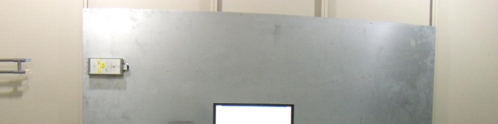
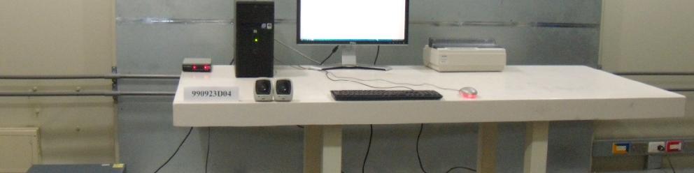
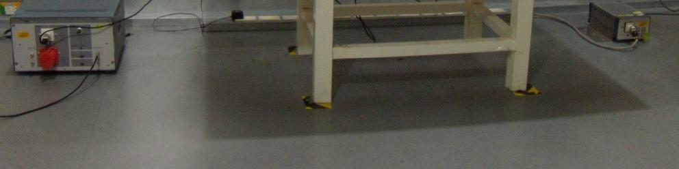
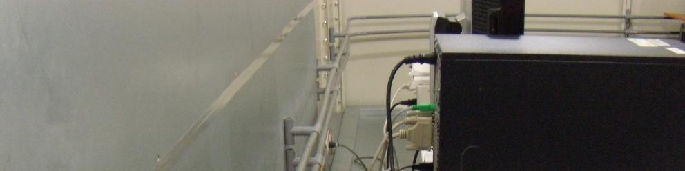


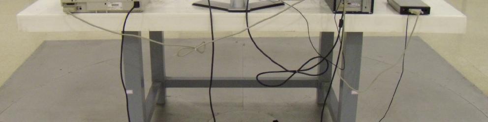
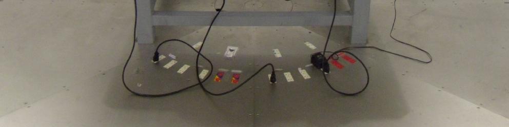
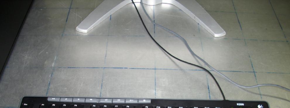
47 6 PHOTOGRAPHS OF THE TEST CONFIGURATION CONDUCTED EMISSION TEST Report No.: CE990923D04 47 Report Format Version 3.0.3


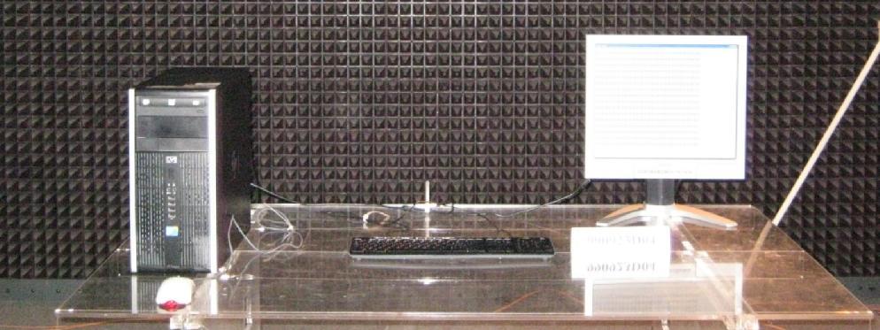
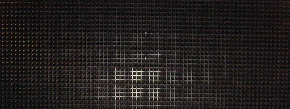
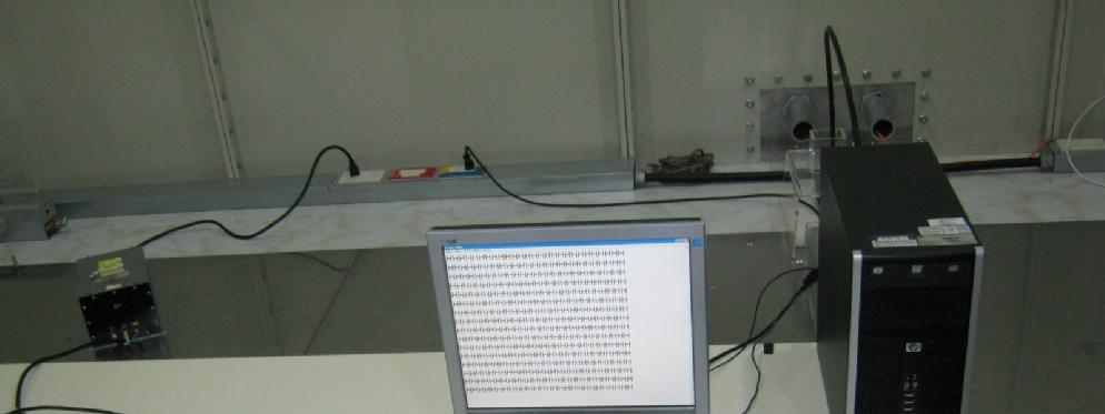
48 RADIATED EMISSION TEST Report No.: CE990923D04 48 Report Format Version 3.0.3


49 ESD TEST ESD TEST POINT Report No.: CE990923D04 49 Report Format Version 3.0.3


50 ESD TEST POINT Report No.: CE990923D04 50 Report Format Version 3.0.3

51 RS TEST Report No.: CE990923D04 51 Report Format Version 3.0.3


52 EFT TEST CONDUCTED SUSCEPTIBILITY TEST Report No.: CE990923D04 52 Report Format Version 3.0.3


53 POWER-FREQUENCY MAGNETIC FIELDS TEST Report No.: CE990923D04 53 Report Format Version 3.0.3
54 7 APPENDIX - INFORMATION ON THE TESTING LABORATORIES We, Bureau Veritas Consumer Products Services (H.K.) Ltd., Taoyuan Branch, were founded in 1988 to provide our best service in EMC, Radio, Telecom and Safety consultation. Our laboratories are accredited and approved according to ISO/IEC Copies of accreditation certificates of our laboratories obtained from approval agencies can be downloaded from our web site: If you have any comments, please feel free to contact us at the following: Linko EMC/RF Lab: Tel: Fax: Hsin Chu EMC/RF Lab: Tel: Fax: Hwa Ya EMC/RF/Safety/Telecom Lab: Tel: Fax: service@adt.com.tw Web Site: The address and road map of all our labs can be found in our web site also. --- END --- Report No.: CE990923D04 54 Report Format Version 3.0.3
FCC DoC TEST REPORT. TESTED : Sep. 01 to 02, 2010 APPLICANT : LOGITECH FAR EAST LTD.
 FCC DoC TEST REPORT REPORT NO. : FD990901E04 MODEL NO. : Y-R0016 RECEIVED : Sep. 01, 2010 TESTED : Sep. 01 to 02, 2010 ISSUED DATE : Sep. 07, 2010 APPLICANT : LOGITECH FAR EAST LTD. ADDRESS : #2 Creation
VCCI TEST REPORT. TESTED : June 22 to 23, 2010 APPLICANT : LOGITECH FAR EAST LTD.
 VCCI TEST REPORT REPORT NO. : V990621E07 MODEL NO. : M-U0026 RECEIVED : June 21, 2010 TESTED : June 22 to 23, 2010 ISSUED : June 24, 2010 APPLICANT : LOGITECH FAR EAST LTD. ADDRESS : #2 Creation Rd. 4,
EMC TEST REPORT. ADDRESS : #2 Creation Rd. 4, Science-Based Ind. Park Hsinchu Taiwan, R.O.C.
 EMC TEST REPORT REPORT NO. : RM110613E07 MODEL NO. : M-R0027 RECEIVED : June 13, 2011 TESTED : June 17, 2011 ISSUED : June 22, 2011 APPLICANT : LOGITECH FAR EAST LTD. ADDRESS : #2 Creation Rd. 4, Science-Based
FCC DoC TEST REPORT. ADDRESS : #2 Creation Rd. 4, Science-Based Ind. Park Hsinchu Taiwan, R.O.C.
 FCC DoC TEST REPORT REPORT NO. : FD981207H01 MODEL NO. : N-I0004 RECEIVED : Dec 07, 2009 TESTED : Dec. 08, 2009 ISSUED: Dec. 14, 2009 APPLICANT : LOGITECH FAR EAST LTD. ADDRESS : #2 Creation Rd. 4, Science-Based
FCC DoC TEST REPORT. ADDRESS : #2 Creation Rd. 4, Science-Based Ind. Park Hsinchu Taiwan, R.O.C.
 FCC DoC TEST REPORT REPORT NO. : FD990811E03 MODEL NO. : A-E0001 RECEIVED : Aug. 11, 2010 TESTED : Aug. 13 to 17, 2010 ISSUED DATE : Aug. 20, 2010 APPLICANT : LOGITECH FAR EAST LTD. ADDRESS : #2 Creation
FCC TEST REPORT. ADDRESS: #2 Creation Rd. 4, Science-Based Ind. Park Hsinchu Taiwan, R.O.C.
 FCC TEST REPORT REPORT NO.: RF991014E04 MODEL NO.: M-R0018 FCC ID: JNZMR0018 RECEIVED: Oct. 14, 2010 TESTED: Oct. 19, 2010 ISSUED: Oct. 22, 2010 APPLICANT: LOGITECH FAR EAST LTD. ADDRESS: #2 Creation Rd.
FCC TEST REPORT (RFID)
") FCC TEST REPORT (RFID) REPORT NO.: RF130923D14-2 MODEL NO.: DC-NU2-UMPC FCC ID: 2AA69001 RECEIVED: Sep. 23, 2013 TESTED: Oct. 11 ~ 17, 2013 ISSUED: Oct. 25, 2013 APPLICANT: Capsule Technologie SAS ADDRESS:
FCC TEST REPORT (RFID) REPORT NO.: RF130923D14-2 MODEL NO.: DC-NU2-UMPC FCC ID: 2AA69001 RECEIVED: Sep. 23, 2013 TESTED: Oct. 11 ~ 17, 2013 ISSUED: Oct. 25, 2013 APPLICANT: Capsule Technologie SAS ADDRESS:
FCC DoC TEST REPORT. ISSUED BY : Bureau Veritas Consumer Products Services (H.K.) Ltd., Taoyuan Branch Hsin Chu Laboratory
 Ltd., Taoyuan Branch Hsin Chu Laboratory") FCC DoC TEST REPORT REPORT NO. : FD110511E05 MODEL NO. : A-00033 RECEIVED : May 11, 2011 TESTED : May 13, 2011 ISSUED: June 30, 2011 APPLICANT : Logitech Inc. ADDRESS : 6505 Kaiser Drive, Fremont, CA 94555
FCC DoC TEST REPORT REPORT NO. : FD110511E05 MODEL NO. : A-00033 RECEIVED : May 11, 2011 TESTED : May 13, 2011 ISSUED: June 30, 2011 APPLICANT : Logitech Inc. ADDRESS : 6505 Kaiser Drive, Fremont, CA 94555
FCC TEST REPORT. SendFar Technology Co., Ltd.
 FCC TEST REPORT REPORT NO.: RF921021R02 MODEL NO.: WPC-3110 RECEIVED: October 21, 2003 TESTED: November 14 ~ November 16, 2003 APPLICANT: ADDRESS: SendFar Technology Co., Ltd. 15FL., NO.866-2, JUNGJENG
FCC TEST REPORT. LAB ADDRESS: No. 47, 14 th Ling, Chia Pau Tsuen, Linko Hsiang 244, Taipei Hsien, Taiwan, R.O.C.
 FCC TEST REPORT REPORT NO.: RF951204L06A MODEL NO.: WRT54G V8 RECEIVED: Jan. 13, 2007 TESTED: Jan. 13 ~ Jan. 16, 2007 ISSUED: Jan. 17, 2007 APPLICANT: Cisco-Linksys LLC ADDRESS: 121 Theory Drive Irvine,
EMC TEST REPORT. Report No.: CE10-LIE040101E
 EMC TEST REPORT Report No.: CE10-LIE040101E Product: LED TUBE Model No.: T10, T8, T5 Applicant: Shenzhen Saiju Electronic Co., Ltd. Address: 2nd. Xianshun Industrial Park, Gushu, Xixiang, Bao an, Shenzhen,
EMC TEST REPORT For MPP SOLAR INC Inverter/ Charger Model Number : PIP 4048HS
 EMC-E20130903E EMC TEST REPORT For MPP SOLAR INC Inverter/ Charger Model Number : PIP 4048HS Prepared for : MPP SOLAR INC Address : 4F, NO. 50-1, SECTION 1, HSIN-SHENG S. RD. TAIPEI, TAIWAN Prepared by
FCC TEST REPORT th Lin, Chiapau Tsun, Linko, Taipei, Taiwan, R.O.C. No. 19, Hwa Ya 2 nd Rd., Kueishan, Taoyuan, Taiwan, R.O.C.
 FCC TEST REPORT REPORT NO.: RF941130L05 MODEL NO.: WAP54G ver. 3.1 RECEIVED: Jan. 23, 2006 TESTED: Jan. 23 ~ Feb. 27, 2006 ISSUED: Mar. 02, 2006 APPLICANT: Cisco-Linksys LLC ADDRESS: 121 Theory Drive Irvine,
Equipment : UPS Brand Name : Test Model No. : SRT3000RMXLW-IEC Multiple Listing :
 Equipment : UPS Brand Name : Test Model No. : SRT3000RMXLW-IEC Multiple Listing : SRT3000RMXLTxxxxxxxxxx SRT (means series name) 3000 (means maximum VA output) RM (means Rack Mounted) or none (means Tower
TEST REPORT. Building 6,XinXinTian Industrial Park, XinSha Road, ShaJing, Baoan District, ShenZhen, China
 TEST REPORT Applicant Address Innokin Technology Co.,Ltd Building 6,XinXinTian Industrial Park, XinSha Road, ShaJing, Baoan District, ShenZhen, China Manufacturer or Supplier Address Product Innokin Technology
TEST REPORT. Building 6, XinXinTian Industrial Park, XinSha Road, ShaJing, Baoan District, ShenZhen, China. Shenzhen Innokin Technology Co.
 TEST REPORT Applicant Address Shenzhen Innokin Technology Co., Ltd Building 6, XinXinTian Industrial Park, XinSha Road, ShaJing, Baoan District, ShenZhen, China Manufacturer or Supplier Address Product
ITUNER NETWORKS CORPORATION EMC REPORT Fremont Blvd. Fremont, CA
 Shenzhen BST Technology Co., Ltd. ITUNER NETWORKS CORPORATION EMC REPORT Prepared For : ITUNER NETWORKS CORPORATION 47801 Fremont Blvd. Fremont, CA. 94538 Product Name: PicoPSU-150 Trade Name: PicoPSU
TEST REPORT. Table of Contents
 Page:2 of 24 Table of Contents 1. DOCUMENT POLICY AND TEST STATEMENT... 3 1.1 DOCUMENT POLICY...3 1.2 TEST STATEMENT...3 2. DESCRIPTION OF EUT AND TEST MODE... 4 2.1 GENERAL DESCRIPTION OF EUT...4 2.2
EMC TEST REPORT. for. Coliy Technology Co.,Ltd. Fluxgate Gaussmeter
 Page 1 of 48 EMC TEST REPORT for Coliy Technology Co.,Ltd. Fluxgate Gaussmeter Prepared for : Coliy Technology Co.,Ltd. Address : Block B,9 th Floor,Xinzhongtai Business Building,Gushu 2nd Road,Xi Town,Bao
FCC TEST REPORT. ISSUED BY: Bureau Veritas Consumer Products Services (H.K.) Ltd., Taoyuan Branch
 Ltd., Taoyuan Branch") FCC TEST REPORT REPORT NO.: RF140730D07 MODEL NO.: F5L174 FCC ID: K7SF5L174 RECEIVED: Jul. 30, 2014 TESTED: Aug. 22 ~ 28, 2014 ISSUED: Aug. 29, 2014 APPLICANT: Belkin International, Inc. ADDRESS: 12045
FCC TEST REPORT REPORT NO.: RF140730D07 MODEL NO.: F5L174 FCC ID: K7SF5L174 RECEIVED: Jul. 30, 2014 TESTED: Aug. 22 ~ 28, 2014 ISSUED: Aug. 29, 2014 APPLICANT: Belkin International, Inc. ADDRESS: 12045
FCC TEST REPORT. ISSUED BY: Bureau Veritas Consumer Products Services (H.K.) Ltd., Taoyuan Branch
 Ltd., Taoyuan Branch") FCC TEST REPORT REPORT NO.: RF140728D03 MODEL NO.: F5L171 FCC ID: K7SF5L171 RECEIVED: Jul. 28, 2014 TESTED: Aug. 21 ~ 22, 2014 ISSUED: Aug. 26, 2014 APPLICANT: Belkin International, Inc. ADDRESS: 12045
FCC TEST REPORT REPORT NO.: RF140728D03 MODEL NO.: F5L171 FCC ID: K7SF5L171 RECEIVED: Jul. 28, 2014 TESTED: Aug. 21 ~ 22, 2014 ISSUED: Aug. 26, 2014 APPLICANT: Belkin International, Inc. ADDRESS: 12045
Prepared for Address. : KST DIGITAL TECHNOLOGY LIMITED : No.226, Pangu Street, Meixian, Meizhou, Guangdong. Prepared by
 EMC TEST REPORT For KST DIGITAL TECHNOLOGY LIMITED Coreless Servo Model No.: X12-508 Additional Model No.: DS215MG, DS315MG, DS213MG, DS313MG, DS12C, DS12T, X12-306 Prepared for Address : KST DIGITAL TECHNOLOGY
FCC 47 CFR PART 15 SUBPART B
 FCC 47 CFR PART 15 SUBPART B TEST REPORT For DC TO DC CONVERTER Model : D100 Series Issued for MicroPower Direct, LLC 232 Tosca Drive Stoughton, MA02072 U.S.A. Issued by Compliance Certification Services
Equipment : AC/DC ADAPTER Test Model No. : ADP-90MD H Applicant : DELTA ELECTRONICS, INC. Test Report No. : CE130910D06
 Equipment : AC/DC ADAPTER Test Model No. : ADP-90MD H Applicant : DELTA ELECTRONICS, INC. Test Report No. : CE130910D06 We, Bureau Veritas Consumer Products Services (H.K.) Ltd., Taoyuan Branch, declare
FCC TEST REPORT. ISSUED BY: Bureau Veritas Consumer Products Services (H.K.) Ltd., Taoyuan Branch
 Ltd., Taoyuan Branch") FCC TEST REPORT REPORT NO.: RF971218L04 MODEL NO.: ESR-9753 (Refer to item 3.1 for more detail) RECEIVED: Dec. 18, 2008 TESTED: Dec. 22 ~ Dec. 25, 2008 ISSUED: Dec. 31, 2008 APPLICANT: Senao Networks Inc.
FCC TEST REPORT REPORT NO.: RF971218L04 MODEL NO.: ESR-9753 (Refer to item 3.1 for more detail) RECEIVED: Dec. 18, 2008 TESTED: Dec. 22 ~ Dec. 25, 2008 ISSUED: Dec. 31, 2008 APPLICANT: Senao Networks Inc.
FCC 15B Test Report. : BTv4.0 Dual Mode USB Dongle. Address : Thompson Ave. / Lenexa, Kansas / / USA
 FCC 15B Test Report Equipment Model No. Brand Name Applicant : BTv4.0 Dual Mode USB Dongle : BT820 : Laird Technologies : Laird Technologies Address : 11160 Thompson Ave. / Lenexa, Kansas / 66219 / USA
EMC TEST REPORT. according to
 EMC TEST REPORT according to European Standard EN 55022:2006/A1:2007 Class B, EN 61000-3-2:2006, EN 61000-3-3:1995/A1:2001/A2:2006, EN 55024:1998/A1:2001/A2:2003 (IEC 61000-4-2:Edition 1.2:2001-04, IEC
VCCI TEST REPORT. According to. V-3/ , TECHNICAL REQUIREMENTS, Class B ITE. Equipment : USB video camera. Model No. : V-U0017 / V-U0021
 VCCI TEST REPORT According to V-3/2009.04, TECHNICAL REQUIREMENTS, Class B ITE Equipment : USB video camera Model No. : V-U0017 / V-U0021 Applicant : Logitech Far East Ltd. 2 Creation Road IV, Science-Based
APPLICATION FOR EMC DIRECTIVE. On Behalf of. Shenzhen Qinhan Lighting Co., Ltd. led flood light. Trade Name:
 APPLICATION FOR EMC DIRECTIVE On Behalf of Shenzhen Qinhan Lighting Co., Ltd led flood light Trade Name: Model: QH-TGC-400W, QH-TGC-300W, QH-TGC-500W, QH-TGC-800W, QH-TGC-1000W Prepared For : Shenzhen
CE EMC TEST REPORT VIVOTEK INC.
 CE EMC TEST REPORT REPORT NO.: CE921001R05 MODEL NO.: IP 2112 / IP 2122 RECEIVED: October 16, 2003 TESTED: October 16~ November 03, 2003 APPLICANT: ADDRESS: VIVOTEK INC. 6F, No.192, Lien-Chen Rd., Chung-Ho,
FCC TEST REPORT (WLAN )
") FCC TEST REPORT (WLAN 15.247) REPORT : RF130923D14 MODEL : DC-NU2-UMPC FCC ID: 2AA69001 RECEIVED: Sep. 23, 2013 TESTED: Sep. 24 ~ Oct. 24, 2013 ISSUED: Oct. 25, 2013 APPLICANT: Capsule Technologie SAS
FCC TEST REPORT (WLAN 15.247) REPORT : RF130923D14 MODEL : DC-NU2-UMPC FCC ID: 2AA69001 RECEIVED: Sep. 23, 2013 TESTED: Sep. 24 ~ Oct. 24, 2013 ISSUED: Oct. 25, 2013 APPLICANT: Capsule Technologie SAS
CE EMC TEST REPORT. TESTED : June 22 to 23, 2010 APPLICANT : LOGITECH FAR EAST LTD.
 CE EMC TEST REPORT REPORT NO. : CE990621E07 MODEL NO. : M-U0026 RECEIVED : June 21, 2010 TESTED : June 22 to 23, 2010 ISSUED : June 24, 2010 APPLICANT : LOGITECH FAR EAST LTD. ADDRESS : #2 Creation Rd.
FCC TEST REPORT. Summit Data Communications, Inc. Advance Data Technology Corporation
 FCC TEST REPORT REPORT NO.: RF950331L08 MODEL NO.: SDC-MCF10G RECEIVED: Jun. 05, 2006 TESTED: Jun. 05 ~ 22, 2006 ISSUED: Jun. 26, 2006 APPLICANT: ADDRESS: Summit Data Communications, Inc. 526 South Main
ELECTRONICS TESTING CENTER(ETC), TAIWAN
, TAIWAN") File No. : 06-03-RBF-111-01 EMC TESTING DEPARTMENT II Page: 1 / 35 TEST REPORT Responsible Party Manufacturer Description of Product Trade Name : Huan Vu Enterprise Co., Ltd. : Huan Vu Enterprise Co.,
File No. : 06-03-RBF-111-01 EMC TESTING DEPARTMENT II Page: 1 / 35 TEST REPORT Responsible Party Manufacturer Description of Product Trade Name : Huan Vu Enterprise Co., Ltd. : Huan Vu Enterprise Co.,
TEST REPORT. Table of Contents
 Page:2 of 28 Table of Contents 1. DOCUMENT POLICY AND TEST STATEMENT... 3 1.1 DOCUMENT POLICY... 3 1.2 TEST STATEMENT... 3 2. DESCRIPTION OF EUT AND TEST MODE... 4 2.1 GENERAL DESCRIPTION OF EUT... 4 2.2
1 SUMMARY OF STANDARDS AND RESULTS
 1 SUMMARY OF STANDARDS AND RESULTS 1.1 Description of Standards and Results The EUT have been tested according to the applicable standards as referenced below: EMISSION Description of Test Item Standard
TEST REPORT. The submitted sample of the above equipment has been tested for according to the requirements of the following standards:
 TEST REPORT Applicant Address Innokin Technology Co., Ltd Building 6, XinXinTian Industrial Park, XinSha Road, ShaJing, Baoan District, ShenZhen, China Manufacturer or Supplier Address Product Innokin
TEST REPORT... 1 CONTENT...
 CONTENT TEST REPORT... 1 CONTENT... 2 1 TEST RESULTS SUMMARY... 3 2 EMC RESULTS CONCLUSION... 4 3 LABORATORY MEASUREMENTS... 6 4 EMI TEST... 7 4.1 CONTINUOUS CONDUCTED DISTURBANCE VOLTAGE TEST... 7 4.2
TEST REPORT. Table of Contents
 Page:2 of 35 Table of Contents 1. DOCUMENT POLICY AND TEST STATEMENT... 4 1.1 DOCUMENT POLICY...4 1.2 TEST STATEMENT...4 1.3 EUT MODIFICATION...4 2. DESCRIPTION OF EUT AND TEST MODE... 5 2.1 GENERAL DESCRIPTION
CE EMC Test Report. Report No.: CE151201D13. Test Model: UE-1008
 CE EMC Test Report Report No.: CE151201D13 Test Model: UE-1008 Series Model: Vecow UE Series, UE-1004, UE-XXXXXXXXXX ( X can be 0-9, A-Z or blank for marketing purpose) Received Date: Dec. 1, 2015 Test
Test Report. Guangdong East Power Co., Ltd. Fully Automatic AC Voltage Regulator. Brand Name:
 Test Report Applicant: Product Name: Brand Name: Model No.: Guangdong East Power Co., Ltd. Fully Automatic AC Voltage Regulator EAST ZTY-30KVA Date of Receipt : Aug. 30, 2013 Date of Test: Sep. 03, 2013
FCC Test Report (15.249)
") FCC Test Report (15.249) Report No.: FCC ID: Test Model: RF150529E01 JNZNR0010 N-R0010 Received Date: May 29, 2015 Test Date: June 04 to 08, 2015 Issued Date: June 16, 2015 Applicant: LOGITECH FAR EAST
FCC Test Report (15.249) Report No.: FCC ID: Test Model: RF150529E01 JNZNR0010 N-R0010 Received Date: May 29, 2015 Test Date: June 04 to 08, 2015 Issued Date: June 16, 2015 Applicant: LOGITECH FAR EAST
EMC TEST REPORT For. Shenzhen Ruideou Keji Youxian Gongsi. Shenzhen Ruideou Keji Youxian Gongsi
 EMC TEST REPORT For Shenzhen Ruideou Keji Youxian Gongsi Product Name: Trademark: Milligram Scale WAOAW Model Number: W-01-50 Prepared For : Address: Prepared By : Address: Shenzhen Ruideou Keji Youxian
VCCI TEST REPORT. According to. Class B ITE. Equipment : USB video camera
 VCCI TEST REPORT According to Class B ITE Equipment : USB video camera Model No. : V-U0011 Applicant : Logitech Far East Ltd. 2 Creation Road IV, Science-Based Ind. Park, Hsinchu, Taiwan. The test result
EMC TEST REPORT. For. Switching Mode Power Adaptor. Model No.: 9W/14.4V/EU(18V/1.0A), 19W/14.4V/EU(12V/1.5A)
, 19W/14.4V/EU(12V/1.5A)") EMC TEST REPORT For Company Limited Liability «Faraday Electronics» Switching Mode Power Adaptor Model No.: 9W/14.4V/EU(18V/1.0A), 19W/14.4V/EU(12V/1.5A) Prepared For : Company Limited Liability «Faraday
EMC TEST REPORT For Company Limited Liability «Faraday Electronics» Switching Mode Power Adaptor Model No.: 9W/14.4V/EU(18V/1.0A), 19W/14.4V/EU(12V/1.5A) Prepared For : Company Limited Liability «Faraday
TEST REPORT. Table of Contents
 Page:2 of 43 Table of Contents 1. DOCUMENT POLICY AND TEST STATEMENT... 4 1.1 DOCUMENT POLICY... 4 1.2 TEST STATEMENT... 4 2. DESCRIPTION OF EUT AND TEST MODE... 4 2.1 GENERAL DESCRIPTION OF EUT... 4 2.2
EMC TEST REPORT for LEDELS LIGHTING CO., LTD. LED module Model No. : LL-F12T4815X6B
 Page 1 of 27 Report No. R011412016E-1 EMC TEST REPORT for LEDELS LIGHTING CO., LTD LED module Model No. : LL-F12T4815X6B Prepared for : LEDELS LIGHTING CO., LTD Address : 5F, Block C, Mingjinhai Ind. Park,
CE TEST CERTIFICATION
 according to Certification No.: E5NC004 European Standard EN 61000-6-4:2001 EN 61000-3-2: 2000, EN 61000-3-3:1995/A1:2001 and EN 61000-6-2:2001 ( IEC 61000-4-2:1995/A1:1998, IEC 61000-4-3: 1995/A1:1998,
EN 55015: 2013 Clause Pass. EN 55015: 2013 Clause Pass. EN 55015: 2013 Clause Pass
 Reference No.: WTD15S0730643E Page 2 of 42 1 Test Summary Test Item Conducted Disturbance at Mains Terminal, 9kHz to 30MHz Radiation electromagnetic disturbance, 9kHz to 30MHz Radiation Emission, 30MHz
EMC TEST REPORT for : DONGGUAN EVER DEVELOPMENT ELECTRONIC CO., Electronic calculator Model No.: KF15758
 Page 1 of 20 Report No. R011604553E EMC TEST REPORT for DONGGUAN EVER DEVELOPMENT ELECTRONIC CO., LTD. Electronic calculator Model No.: KF15758 Prepared for Address Prepared by Address : DONGGUAN EVER
EMC TEST REPORT For ShenZhen ZhangQing Electronic LTD poe tester Model No.: WS POE Tester/Detector Additional Model No: Please Refer to Page 8
 EMC TEST REPORT For ShenZhen ZhangQing Electronic LTD poe tester Model No.: WS POE Tester/Detector Additional Model No: Please Refer to Page 8 Prepared for Address : ShenZhen ZhangQing Electronic LTD :
CE EMC Test Certification
 Certification No.: EC57C001 CE EMC Test Certification According to European Standard EN 55022:1998/A1:2000/A2:2003 Class A, EN 61000-3-2: 2000, EN 61000-3-3:1995/A1:2001 and EN 55024:1998/A1:2001/A2:2003
FCC Verification Test Report
 FCC Verification Test Report Report No.: Test Model: FV141111C02 SPC-2845 Series Model: Vecow SPC Series, SPC-2145, SPC-2845-W4, SPC-2845X, SPC-2845R, SPC-2845D, SPC-XXXXXXXXXX ( X can be 0-9, A-Z or blank
EMC REPORT. ShenZhen KY Technology Co.,Ltd. No.369, BaoTian 1st RD, TieGang Industrial Park, Xixiang Town, Baoan District, ShenZhen, PRC.
 Report No.: UNI2016121702ER-01 Page 1 / 30 ShenZhen KY Technology Co.,Ltd EMC REPORT Prepared For: ShenZhen KY Technology Co.,Ltd Product Name: Smart bracelet No.369, BaoTian 1st RD, TieGang Industrial
Shenzhen Toby Technology Co., Ltd. EMC Test Report. Report No.: TB-EMC Page: 1 of 20
 Shenzhen Toby Technology Co., Ltd. Report No.: TB-EMC125641 Page: 1 of 20 EMC Test Report Application No. : TB12114299 Applicant : Newmb Technology Co., Ltd. Equipment Under Test (EUT) EUT Name : USB HUB
RADIO TEST REPORT (AS/NZS 4268)
") RADIO TEST REPORT (AS/NZS 4268) REPORT NO.: RC990901E04 MODEL NO.: Y-R0016 RECEIVED: Sep. 01, 2010 TESTED: Sep. 01 to 02, 2010 ISSUED: Sep. 08, 2010 APPLICANT: LOGITECH FAR EAST LTD. ADDRESS: #2 Creation
RADIO TEST REPORT (AS/NZS 4268) REPORT NO.: RC990901E04 MODEL NO.: Y-R0016 RECEIVED: Sep. 01, 2010 TESTED: Sep. 01 to 02, 2010 ISSUED: Sep. 08, 2010 APPLICANT: LOGITECH FAR EAST LTD. ADDRESS: #2 Creation
FCC TEST REPORT. for. 47 CFR, Part 15, Subpart C. SPORTON International Inc.
 FCC TEST REPORT for 47 CFR, Part 15, Subpart C Equipment Trade Name Model No. FCC ID Filing Type Applicant : GamePad : Genius : Wireless G-12X : FSUGG0005 : Certification : KYE Systems Corp. No. 492, Sec.
EMC TEST REPORT For INNOKIN TECHNOLOGY CO., LIMITED. ITaste vv. Model No.: ITaste vv
 EMC TEST REPORT For INNOKIN TECHNOLOGY CO., LIMITED ITaste vv Model No.: ITaste vv Prepared for : INNOKIN TECHNOLOGY CO., LIMITED Address : 3# Floor, #B Building, Heng Chang Rong Industrial Park, Gonghe
EMC TEST REPORT for SHENZHEN MUST ENERGY TECHNOLOGY CO., LTD
 Page 1 of 45 Report No. R011607240E EMC TEST REPORT for SHENZHEN MUST ENERGY TECHNOLOGY CO., LTD INVERTER CHARGER Model No.: PV35-4K DC24V MPK, PV35-4K DC48V MPK, PV35-5K DC48V MPK, PV35-6K DC48V MPK Prepared
APPLICATION FOR CERTIFICATION On Behalf of Futaba Corporation Radio Control Model No.:T10CG-2.4G FCC ID:AZPT10CG-24G Brand : Futaba
 FCC ID. AZPT10CG-24G Page 1 of 56 APPLICATION FOR CERTIFICATION On Behalf of Futaba Corporation Radio Control Model No.:T10CG-2.4G FCC ID:AZPT10CG-24G Brand : Futaba Prepared for : Futaba Corporation 1080
Declaration of Conformity (DoC)
") Declaration of Conformity (DoC) Per 47 CFR 2.1077(a) & 15.19(a)(3) The following device is herewith confirmed to comply with Part 15 of the FCC Rules. Product Name : PCIE-USB380,PCIE-USB340 Model No. :
Declaration of Conformity (DoC) Per 47 CFR 2.1077(a) & 15.19(a)(3) The following device is herewith confirmed to comply with Part 15 of the FCC Rules. Product Name : PCIE-USB380,PCIE-USB340 Model No. :
RADIO TEST REPORT (AS/NZS 4268)
") RADIO TEST REPORT (AS/NZS 4268) REPORT NO.: RC991014E04 MODEL NO.: M-R0018 RECEIVED: Oct. 14, 2010 TESTED: Oct. 19, 2010 ISSUED: Oct. 25, 2010 APPLICANT: LOGITECH FAR EAST LTD. ADDRESS: #2 Creation Rd.
RADIO TEST REPORT (AS/NZS 4268) REPORT NO.: RC991014E04 MODEL NO.: M-R0018 RECEIVED: Oct. 14, 2010 TESTED: Oct. 19, 2010 ISSUED: Oct. 25, 2010 APPLICANT: LOGITECH FAR EAST LTD. ADDRESS: #2 Creation Rd.
Overview of EMC Regulations and Testing. Prof. Tzong-Lin Wu Department of Electrical Engineering National Taiwan University
 Overview of EMC Regulations and Testing Prof. Tzong-Lin Wu Department of Electrical Engineering National Taiwan University What is EMC Electro-Magnetic Compatibility ( 電磁相容 ) EMC EMI (Interference) Conducted
FCC TEST REPORT (15.407)
") FCC TEST REPORT (15.407) REPORT : RF141108C01-1 MODEL : AP 100X FCC ID: 2ACTO-AP100X RECEIVED: Nov. 08, 2014 TESTED: Nov. 19 ~ Nov. 26, 2014 ISSUED: Dec. 02, 2014 APPLICANT: Sophos Ltd ADDRESS: The Pentagon,Abingdon,OX14
FCC TEST REPORT (15.407) REPORT : RF141108C01-1 MODEL : AP 100X FCC ID: 2ACTO-AP100X RECEIVED: Nov. 08, 2014 TESTED: Nov. 19 ~ Nov. 26, 2014 ISSUED: Dec. 02, 2014 APPLICANT: Sophos Ltd ADDRESS: The Pentagon,Abingdon,OX14
TEST REPORT. Report No. : EM/2008/80003 Page : 1 of 54
 Equipment Under Test Brand Name Model No. Added Model(s) Applicant Address of Applicant Page : 1 of 54 TEST REPORT : AC Servo Motor : Kingservo : AC 400W servo motor : N/A : Ho Fo Automation CO., LTD :
EN 55022: 2010+AC:2011 Clause 6.1 Pass. Harmonic Current EN :2006+A1:2009+A2:2009 Class A N/A
 Reference No.: WT12106773-N-S-E Page 2 of 33 1 Test Summary Test Item Mains Terminal Disturbance Voltage, 150KHz to 30MHz Radiation Emission, 30MHz to 1000MHz EMISSION Test Standard Class / Severity Result
CE TEST CERTIFICATION
 Certification No.: E5DC001 according to European Standard EN 61000-6-4:2001 EN 61000-3-2: 2000, EN 61000-3-3:1995/A1:2001 and EN 61000-6-2:2001 ( IEC 61000-4-2:1995/A1:1998, IEC 61000-4-3: 1995/A1:1998,
RADIO TEST REPORT. ADDRESS: #2 Creation Rd. 4, Science-Based Ind. Park Hsinchu Taiwan, R.O.C.
 RADIO TEST REPORT REPORT NO.: RJ980526H13 MODEL NO.: M-R0012 RECEIVED: June 02, 2009 TESTED: June 03, 2009 ISSUED: June 12, 2009 APPLICANT: LOGITECH FAR EAST LTD. ADDRESS: #2 Creation Rd. 4, Science-Based
FCC 15B Test Report. : Bluetooth 4.2 Dual Mode USB HCI Module (Refer to item for more details) (Refer to item for more details)
 (Refer to item for more details)") FCC 15B Test Report Equipment Model No. Brand Name Applicant Address Standard : Bluetooth 4.2 Dual Mode USB HCI Module (Refer to item 1.1.1 for more details) : BT850-SA (Refer to item 1.1.1 for more details)
FCC 15B Test Report Equipment Model No. Brand Name Applicant Address Standard : Bluetooth 4.2 Dual Mode USB HCI Module (Refer to item 1.1.1 for more details) : BT850-SA (Refer to item 1.1.1 for more details)
Supplemental Transmit Simultaneously Test Report
 Supplemental Transmit Simultaneously Test Report REPORT NO.: RF141003E10-2 MODEL NO.: EX6150 FCC ID: PY314300283 RECEIVED: Oct. 03, 2014 TESTED: Oct. 09 to Dec. 08, 2014 ISSUED: Jan. 12, 2015 APPLICANT:
EMC TEST REPORT. Report No.: TS EME Model No.: 33XR-A Issued Date: Jan. 08, 2009
 Page 1 of 18 EMC TEST REPORT Report No.: TS08100063-EME Model No.: 33XR-A Issued Date: Jan. 08, 2009 Applicant: Test Method/ Standard: Test By: FLUKE CORP. 6920 Seaway Blvd, M/S 266D Everett, WA 98203
Test Report GUANGDONG EAST POWER CO., LTD
 Test Report Applicant: Product Name: Brand Name: Model No.: GUANGDONG EAST POWER CO., LTD Online High Frequency UPS EAST EA906IIRTS, EA906IIRTH Date of Receipt : Feb. 26, 2014 Date of Test: Mar. 24, 2014
FCC TEST REPORT (WLAN )
") FCC TEST REPORT (WLAN 15.247) REPORT NO.: RF140220D04 MODEL NO.: LAPAC1750 FCC ID: Q87-LAPAC1750 RECEIVED: Feb. 20, 2014 TESTED: Feb. 20 ~ Mar. 24, 2014 ISSUED: Apr. 14, 2014 APPLICANT: Linksys LLC ADDRESS:
FCC TEST REPORT (WLAN 15.247) REPORT NO.: RF140220D04 MODEL NO.: LAPAC1750 FCC ID: Q87-LAPAC1750 RECEIVED: Feb. 20, 2014 TESTED: Feb. 20 ~ Mar. 24, 2014 ISSUED: Apr. 14, 2014 APPLICANT: Linksys LLC ADDRESS:
TEST SUMMARY. Prüfbericht - Nr.: Test Report No.: Seite 2 von 25. Page 2 of 25
 15072259 001 Seite 2 von 25 Page 2 of 25 TEST SUMMARY 4.1.1 HARMONICS ON AC MAINS 4.1.2 VOLTAGE FLUCTUATIONS ON AC MAINS 4.1.3 MAINS TERMINAL CONTINUOUS DISTURBANCE VOLTAGE 4.1.4 DISCONTINUOUS INTERFERENCE
FCC TEST REPORT (Bluetooth)
") FCC TEST REPORT (Bluetooth) REPORT NO.: RF130801C01D MODEL NO.: HB-2000 FCC ID: OGSHB2000 RECEIVED: Aug. 01, 2013 TESTED: Aug. 20 ~ Oct. 18, 2013 ISSUED: Oct. 21, 2013 APPLICANT: Applied Wireless identifications
FCC TEST REPORT (Bluetooth) REPORT NO.: RF130801C01D MODEL NO.: HB-2000 FCC ID: OGSHB2000 RECEIVED: Aug. 01, 2013 TESTED: Aug. 20 ~ Oct. 18, 2013 ISSUED: Oct. 21, 2013 APPLICANT: Applied Wireless identifications
FCC CLASS B COMPLIANCE REPORT (DoC)
") FCC CLASS B COMPLIANCE REPORT (DoC) for Electromagnetic Emissions Of ENTRY LEVEL IP PHONE Trade Name : XONTEL Model Number : XT-19P Serial Number : N/A Report Number : PZD1611741-F Date : Regulations :
FCC CLASS B COMPLIANCE REPORT (DoC) for Electromagnetic Emissions Of ENTRY LEVEL IP PHONE Trade Name : XONTEL Model Number : XT-19P Serial Number : N/A Report Number : PZD1611741-F Date : Regulations :
EMI Test Report. : BTv4.0 Dual Mode USB Dongle
 EMI Test Report Equipment Model No. Brand Name Applicant Address Standard : BTv4.0 Dual Mode USB Dongle : BT820 : Laird Technologies : Laird Technologies Received Date : Jan. 23, 2017 W66N220 Commerce
Harmonic Current emission EN :2014 Class A Pass. Voltage Fluctuation and Flicker EN :2013 Clause 5 Pass
 Reference No.: WTS15F0323845E Page 2 of 33 1 Test Summary Test Item Mains Terminal Disturbance Voltage, 148.5kHz to 30MHz Disturbance Power, 30MHz to 300MHz Discontinuous Disturbance (Click) Radiated Emission,
FCC SUPPLEMENTARY TEST REPORT
 FCC SUPPLEMENTARY TEST REPORT REPORT NO.: RF960612H07C MODEL NO.: WRP400 RECEIVED: Apr. 24, 2009 TESTED: June 05 to July 10, 2009 ISSUED: July 13, 2009 APPLICANT: Cisco-Linksys LLC ADDRESS: 121 Theory
EMC Test Report. Report Number: M030826
 Page 1 of 36 EMC Technologies Pty Ltd ABN 82 057 105 549 57 Assembly Drive Tullamarine Victoria Australia 3043 Ph: + 613 9335 3333 Fax: + 613 9338 9260 email: melb@emctech.com.au EMC Test Report Report
SUZHOU MAILI ELECTRICAL APPLIANCE CO., LTD NO.666,JIANLIN RD, XUGUAN SUBAREA, SUZHOU HIGH-TECH ZONE
 EMC TEST REPORT For SUZHOU MAILI ELECTRICAL APPLIANCE CO., LTD Product Name: Pure sine wave power inverter Trademark: Model : Prepared For : Address: Prepared By : Address: ML-1000W ML-300W---ML-8000W.
C-Tick EMC TEST REPORT. For. AC/DC Switching Power Supply
 C-Tick EMC TEST REPORT For AC/DC Switching Power Supply Model: CP0515(5V/1.5A); CP0520(5V/2A); CP0530 (5V/3A); CP0540 (5V/4A); CP0550 (5V/5A); CP0560 (5V/6A);CP0615(6V/1.5A); CP0620(6V/2A); CP0625 (6V/2.5A);
PT. SARANA KARYA SOLUSINDO.
 Shenzhen BST Technology Co., Ltd. PT. SARANA KARYA SOLUSINDO. EMC REPORT Prepared For : PT. SARANA KARYA SOLUSINDO. Puri Surya Jaya J1. 29 Cluster Vancouver, Gedangan, Sidoarjo, Jawa Timur - Indonesia
CERTIFICATE. Issued Date: Apr. 20, 2006 Report No.: 064L079-IT-US-P01V01
 CERTIFICATE Issued Date: Apr. 20, 2006 Report No.: 064L079-IT-US-P01V01 This is to certify that the following designated product Product : 19 inch Rack-mounted Data Acquisition Computer Trade name : Moxa
FCC Verification Test Report
 FCC Verification Test Report Report No.: Test Model: FV130424E06E VC-A50, PTC-120 Series Model: VC-X50, VC-X30, VC-501, VC-502, VC-301, VC-302, VC-302X, VC-502X, VC-A50X (where X can be A to Z for marketing
FCC TEST REPORT (Z-Wave)
") FCC TEST REPORT (Z-Wave) REPORT NO.: RF130927E08E-2 MODEL NO.: FiOS-G1100 FCC ID: 2ABTEG1100 RECEIVED: Sep. 27, 2013 TESTED: Oct. 07 to Dec. 06, 2013 ISSUED: Mar. 21, 2014 APPLICANT: Verizon Online LLC
FCC TEST REPORT (Z-Wave) REPORT NO.: RF130927E08E-2 MODEL NO.: FiOS-G1100 FCC ID: 2ABTEG1100 RECEIVED: Sep. 27, 2013 TESTED: Oct. 07 to Dec. 06, 2013 ISSUED: Mar. 21, 2014 APPLICANT: Verizon Online LLC
RADIO TEST REPORT. ADDRESS: #2 Creation Rd. 4, Science-Based Ind. Park Hsinchu Taiwan, R.O.C.
 RADIO TEST REPORT REPORT NO.: RJ991014E04 MODEL NO.: M-R0018 RECEIVED: Oct. 14, 2010 TESTED: Oct. 19, 2010 ISSUED: Oct. 22, 2010 APPLICANT: LOGITECH FAR EAST LTD. ADDRESS: #2 Creation Rd. 4, Science-Based
FCC Test Report. TD-W8961N, TD-W8961ND (refer to item 3.1 for more details)
") FCC Test Report Report No.: FCC ID: Test Model: RF150625C21 TE7TDW8961NDV4 TD-W8961N, TD-W8961ND (refer to item 3.1 for more details) Received Date: Jun. 25, 2014 Test Date: Jul. 03 ~ Sep. 15, 2015 Issued
FCC Test Report Report No.: FCC ID: Test Model: RF150625C21 TE7TDW8961NDV4 TD-W8961N, TD-W8961ND (refer to item 3.1 for more details) Received Date: Jun. 25, 2014 Test Date: Jul. 03 ~ Sep. 15, 2015 Issued
CE EMC TEST REPORT. LAB LOCATION : No. 81-1, Lu Liao Keng, 9 Ling, Wu Lung Tsuen, Chiung Lin Hsiang, Hsin Chu Hsien, Taiwan
 CE EMC TEST REPORT REPORT NO. : CE951115H04B MODEL NO. : MD15 RECEIVED : Nov. 27, 2006 TESTED : Dec. 04 to 27, 2006 ISSUED: March 07, 2007 APPLICANT : CTC UNION TECHNOLOGIES CO., LTD. ADDRESS : 8F, No.
FCC Part 15 Subpart B
 Report No.: 15A111603E-F Page 1 of 23 Test Report FCC Part 15 Subpart B for Electromagnetic Interference of Product: Managed PoE Industrial Ethernet Switch Trade Name: N/A Model Number: IS-DG512P-2F-8;
FCC 47 CFR PART 15 SUBPART B TEST REPORT
 FCC 47 CFR PART 15 SUBPART B TEST REPORT for 19 Multimedia LCD Monitor MODEL: R19LXXX-IPXXXX (X=A~Z, a~z, 0 ~9, Blank or Slash) Test Report Number: 90406001-D Issued for Winmate Communication INC. 9F,
FCC TEST REPORT. Cisco-Linksys LLC. 121 Theory Drive, Irvine, CA (USA) Advance Data Technology Corporation
 Advance Data Technology Corporation") FCC TEST REPORT REPORT NO.: RF940919L07 MODEL NO.: WMP54G ver. 4.1 RECEIVED: Sep. 19, 2005 TESTED: Sep. 19 ~ Sep. 22, 2005 ISSUED: Sep. 23, 2005 APPLICANT: ADDRESS: Cisco-Linksys LLC 121 Theory Drive,
FCC TEST REPORT REPORT NO.: RF940919L07 MODEL NO.: WMP54G ver. 4.1 RECEIVED: Sep. 19, 2005 TESTED: Sep. 19 ~ Sep. 22, 2005 ISSUED: Sep. 23, 2005 APPLICANT: ADDRESS: Cisco-Linksys LLC 121 Theory Drive,
Discontinuous Disturbance (Click) EN :2006+A1:2009+A2:2011 Clause N/A** Radiated Emission, 30MHz to 1000MHz
 EN :2006+A1:2009+A2:2011 Clause N/A** Radiated Emission, 30MHz to 1000MHz") Reference No.: WTN13F0706038E Page 2 of 40 1 Test Summary Test Item Mains Terminal Disturbance Voltage, 148.5kHz to 30MHz Disturbance Power, 30MHz to 300MHz EMISSION Test Standard Class / Severity Result
Reference No.: WTN13F0706038E Page 2 of 40 1 Test Summary Test Item Mains Terminal Disturbance Voltage, 148.5kHz to 30MHz Disturbance Power, 30MHz to 300MHz EMISSION Test Standard Class / Severity Result
Test Report. Applicant ASUSTeK COMPUTER INC. 4F, No. 150, Li-Te Rd., Peitou, Taipei, Taiwan. Date of Receipt Jan. 28, Issued Date Mar.
 Test Report Product Name Model No. FCC ID. IC ID. WPC Qi 1.1/1.0 compliance wireless charging micro-usb box Wireless Charger MSQ-ASUSWLCHARGER 3568A-ASWLCHARGER Applicant ASUSTeK COMPUTER INC. Address
FCC Test Report (IEEE )
") FCC Test Report (IEEE 802.15.4) Report No.: RF170714C04A-1 FCC ID: ZQAH17 Test Model: A0078 Received Date: July 14, 2017 Test Date: July 26 to Aug. 26, 2017 Issued Date: Sep. 08, 2017 Applicant: Nest Labs,
FCC Test Report (IEEE 802.15.4) Report No.: RF170714C04A-1 FCC ID: ZQAH17 Test Model: A0078 Received Date: July 14, 2017 Test Date: July 26 to Aug. 26, 2017 Issued Date: Sep. 08, 2017 Applicant: Nest Labs,
Guangdong East Power Co., Ltd. Uninterruptible Power Systems
 Test Report Applicant: Product Name: Brand Name: Model No.: Guangdong East Power Co., Ltd. Uninterruptible Power Systems EAST EA8806, EA8804 Date of Receipt : Nov. 01, 2012 Date of Test: Nov. 03, 2012
Test Report. Product Name: Wireless 11g USB Adapter Model No. : MS-6826, UB54G FCC ID. : DoC
 Test Report Product Name: Wireless 11g USB Adapter Model No. : MS-6826, UB54G FCC ID. : DoC Applicant : MICRO-STAR INT L Co., LTD Address : No 69, Li-De st., Jung-He City, Taipei Hsien, Taiwan, R.O.C Date
9. Electrostatic Discharge Immunity Test (ESD)
") 9. Electrostatic Discharge Immunity Test (ESD) Test Mode: Mode 1 Final Test Result : PASS Pass Performance Criteria : A Required Performance Criteria: B Basic Standard : IEC 61000-4-2:Edition 1.2:2001-04
9. Electrostatic Discharge Immunity Test (ESD) Test Mode: Mode 1 Final Test Result : PASS Pass Performance Criteria : A Required Performance Criteria: B Basic Standard : IEC 61000-4-2:Edition 1.2:2001-04
EMC TEST REPORT. NORTE SIRIUS ENTERPRISE CO., LTD , Shin-Sheng St., Chung-Ho Dist, New Taipei City, Taiwan
 Page 1 of 32 EMC TEST REPORT Report No.: TS11020117-EME Model No.: NS-PSE, NS-POINTED, NS-PSQUARE, NS-PF-S, NS-PT, NS-PR, NS-PU, NS-PF-H, NS-BALIBA, NS-FLEXMA Issued Date: Mar. 01, 2011 Applicant: NORTE
EMI Test Report. W66N220 Commerce Court, Cedarburg, Wisconsin 53012, USA : CISPR 32:2015/COR1:2016, Class B AS/NZS CISPR 32:2015, Class B
 EMI Test Report Equipment Model No. Brand Name Applicant Address Standard : Bluetooth 5.0 BLE Dongle : BL654 : Laird : Laird Technologies Received Date : Jan. 30, 2018 W66N220 Commerce Court, Cedarburg,