Bob Brehm, AK6R Chief Engineer Palomar-Engineers.com. Copyright 2015 Palomar Engineers, Inc.
|
|
|
- Diane Riley
- 6 years ago
- Views:
Transcription

1 Bob Brehm, AK6R Chief Engineer Palomar-Engineers.com Copyright 2015 Palomar Engineers, Inc.
2 RFI Workshop Objectives Review fundamentals of Common Mode Noise How ferrites work to suppress Common Mode noise How to use ferrite kits to solve specific common mode noise problems in your shack RF feed lines, rotor control lines AC/DC power lines Noisy devices switching power supplies, wall warts, routers, plasma TV, etc. How to suppress neighborhood common mode noise problems Selecting baluns, ununs and chokes to increase signal level

3 Signal to noise ratio Red = Signal + noise, Green = noise Objective is to reduce noise
4 Got RFI Noise in your shack? Symptoms receiver noise caused by outside sources Clicks, buzzes, birdies, or chirps in your receiver on 1 or more bands High noise level periodic or varies by time of day Receiver overload or desensing of front end with no signal present Motor noise of varying/constant pitch often caused by fans, heater/blower motors, heat pumps, fuel pumps Florescent light crackle or buzzing or arcing sound Switching power supplies, battery chargers, inverters, solar controllers, plasma TV, digital gear GRUNGE"
5 Improve Signal/Noise Ratio Solutions Common mode chokes at RECEIVING end (blocks common mode RFI into receiver) in addition to transmitting end (keeps RF on the antenna) Use common mode chokes (1:1 ununs) to choke noise on signal path AT THE RADIO/ANTENNA TUNER Cube baluns have hi Z (2K-10K ohms) Sleeve baluns snap on or slip on ( ohms Z) Super Chokers (1.5-3K ohms)
6 Testimonial Case WOW... I just tried one of your toroids on my modest antenna system. I have a Hamstick on top of an all aluminum manufactured home. Its the best ground plane one could hope for, and I've made contacts to Korea on 40m with it. Before... on 40m I had an AM background noise of 5S units. I wrapped about 10 turns into one of the toroids right by the radio and the noise floor dropped to below 1 S unit ( not readable on my TS-480s). You know... when I got this from you yesterday, I figured maybe 2 S units if that and the price was right... I am truly amazed by the results!!! Bob K2IU (2/25/2014)
7 Causes and Cures to make ham radio more enjoyable
8 What is RFI? Radio Frequency Interference/Electromagnetic Interference (RFI/EMI) at radio frequencies A radio frequency disturbance that causes an unwanted interruption, degradation, or obstruction to an electrical circuit. Common Sources Radio Transmitters (Amateur, broadcast, consumer devices) Natural: Sun, Cosmic noise, Lightning, atmospheric static Electro-mechanical devices (motors), ignition systems All sources cause rapidly changing electrical currents in the effected device which cause unintended operation(victim)
9 Got Common Mode Noise/RFI? Symptoms caused by your transmitter or antenna Periodic birdies or whistles in your band spectrum Constant or time sequenced high noise level across the entire band AM/FM broadcast signals picked up off frequency Motor whine, buzzing noise, noise pops, directional noise, heater, AC line monitors, baby monitors, etc Switching power supply whine
10 RFI Types that can be suppressed About 60% of customers call to REACT to an RFI symptom in their shack/home or their neighbor s home they think is caused by their radio transmitter and/or antenna. TRANSMITTER RFI About 40% of customers call to CURE an RFI problem caused by outside sources effecting their radio station RECEIVER RFI
11 How is RFI Transferred?
12 RFI Transmission RF SOURCE VICTIM PATH (s) RFI REQUIREMENTS SOURCE of RF Connecting PATH(s) conducted or radiated ( antennas ) VICTIM of interference All three of the above must be present to have an RFI problem. Cure Eliminate the SOURCE, or Block/Choke the PATH, or Protect the VICTIM
13 Typical Antenna" Paths for RFI meters AC lines, Phone lines, satellite/cable coax, long CAT-5 cables, ham antennas coax shield, antenna rotor cables, 2 nd story ground wires 20-6 meters speaker wires, device interconnect cables, short Cat-5 cables AM Broadcast same as 160 long antennas FM Broadcast short antennas 3-6 feet long
14 Antenna Lengths Band Freq Mhz 1/4 Wavelength (ft) 1/4 Wavelength (m) wavelength (ft) = 983.6/freq (Mhz) RFI Frequency Antennas M typically longer antennas like AC house wire, telephone system, CAT5, satellite/cable coax 20-2M typically shorter antennas like device interconnect cables, speaker wire. Audio, microphone cables, USB computer cables wavelength (m) = /freq (Mhz)


15 Ferrites Are your Friend for RFI Slip On Bead Snap On Bead Toroid/Ring Reduces common mode current to reduce RFI Cheap, easy to install, work on all ham frequencies Work on all paths (feed line, AC/DC, electronic devices) Lots of options in size, shape to fix most RFI path problems Can be installed by almost anybody who understands how to choose the correct ferrite for a particular RFI problem.
. Reactance goes up as the square of the number of turns, e.g. 2 turns = 4X, 3 turns = 9x, until resonance reached")
16 Ferrite Equivalent Circuit One Turn coil through a ferrite with reactance which varies with frequency (X L =2 *f*l). Reactance goes up as the square of the number of turns, e.g. 2 turns = 4X, 3 turns = 9x, until resonance reached
17 Multi-Bead Choking Z
18 Z Varies with (turns) 2 1 turn = Z 2 turn = 4Z 3 turn = 9 Z More Z = less current = less RFI

19 Ferrite Mixes Different mixes for different frequency ranges of choking. Use at frequencies to the left of peak for chokes. Most popular ham frequency mixes are 31, 43, 61, 77 see website for ranges of each mix.
 or nickel-zinc (43,")
20 Ferrite Mix Selection - Chokes Mix = chemical formula of the iron oxide with manganese-zinc (31, 77) or nickel-zinc (43, 61)
21 Ferrite Use Recap Determine frequency range of RFI Choose proper mix (31, 61, 77) to suppress RFI Choose Topology(slip, snap, ring) to fit the Path Install ferrites retest for RFI suppression Consider additional Paths if RFI persists

22 = Higher Signal/Noise Ratio = MORE DX!

23 RFI Strategy Eliminate/reduce RFI SOURCE or Choke the PATH or Protect the VICTIM
24 Source-Path-Victim in the Ham Shack Source Transmitter or antenna or feedline Path (single or multiple wires in/out of equipment act as TRANSMITTING and RECEIVING antennas) Antenna (direct radiation) Antenna Coax, rotator/antenna selector control lines 120/240V AC wiring Phone/DSL telephone service wires Cable/Satellite coax Device interconnect cables (mic, audio, speaker, video, power) Victim (Device receiving interference I/O wires also act as RECEIVING antennas)
25 Typical Ham Shack ANTENNAS Multiple AC Connections Multiple Antennas/Coax lines Telephone/DSL line Antenna Control Lines Satellite/Cable Coax feed RFI can take multiple paths Antennas can transmit and receive common mode current at radio frequencies (RFI). Your antenna(s) radiate energy that is induced into shack antennas as common mode current
26 Ham Shack RFI Solutions
27 Is your Dipole a Tripole? Coax outside braid as a transmitting antenna Coax outside braid as a receiving antenna Antenna RECEIVER GROUND 1% braid current = 2.75 watt radiation at 1500 watts input, or 1.6 watts at 500 watts input or.7 watts at 100 watts input From antenna feed point to receiver, outside braid receives radiation from antenna and neighborhood devices
28 RFI Chokes for feed line path Path Antenna feed line choke (aka 1:1 balun, 1:1 unun, line isolator, line choke, sleeve baluns) Coax Air Wound frequency dictates # turns for Z (5-10 turns at VHF, small diameter, turns large diameter at HF) In line (ferrite toroids, split beads, sleeve beads) 1:1 balun (voltage (DC grounded) or current) Line isolators (w or w/o ground lug) Examples
29 Coax Balun (aka Ugly balun) Picture: Ugly balun at 7 Mhz, 16 turns, 4.5 diameter = 3,000 Z 20 feet of coax
 RG-8X (1/4 size)")
 150-500")
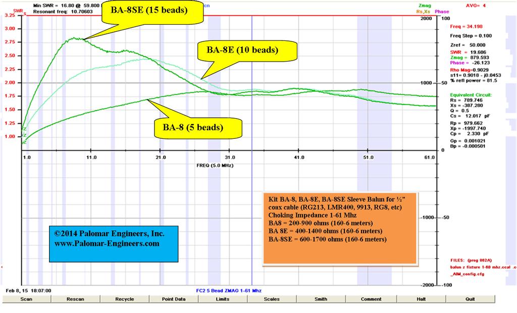
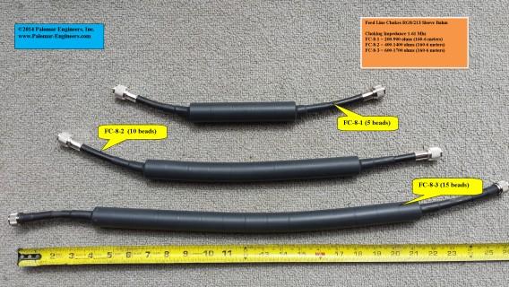
30 Sleeve Baluns (Snap on) RG-8X (1/4 size) ohms RG-213 (1/2 size) ohms
31 Large Clamp On (FSB-1) = 1 ID 3 turns = 1K ohms

32 Sleeve Baluns (Slip on) Palomar BA-8 Balun on Beam Antenna (RG-213)
 Z = 1,500 at 7Mhz,")

33 Super Choker (40-10 Meters) Z = 1,500 at 7Mhz, 2.2K at 10 Mhz, 1K at 14 Mhz, 300 at 28 Mhz 5 Turns, 3 cores


34 CUBE Baluns BA (1:1, 1500w) Z = 2k-10k Feedline choke and noise filter Do It Yourself KIT CB (1:1, 5000w) Z = 3k-12k Feedline choke and noise filter ASSEMBLED
35 RFI Chokes 120/240V AC Path Ring Toroids most effective usually 3-10 turns Snap Ons convenient to use, usually 1-2 turns Big Clamp On s multiple turns, easy to install Example pictures
36 AC Line Chokes Palomar F240 (1.4 ID/2.4 OD) Choke meters, Z = 2-5K range depending on frequency
37 Reducing Common Mode Noise Recap Determine frequency range of RFI Choose proper mix (31, 61, 77) to suppress RFI Choose Topology(slip, snap, ring) to fit the Path Install ferrite chokes on ALL antenna feed lines and control lines at antenna end and receiver end retest for RFI suppression Install ferrite chokes on all victim devices and sources Consider additional Paths if RFI persists Have a low impedance common ground for all radio/computer equipment If you need help Call Palomar Engineers or view specific solutions at
38 DC Power Line Chokes Wall power plug DC power - transceiver Palomar F140 (1.4OD), Z=1K, 5 turn Palomar F240 (1.4OD), Z=2K, 5 turn
39 Device Cable Chokes Toroids Snap On All Input/Output Cables on device Longer cables more important to choke because they are better receiving antennas
40 RFI Kits for specific problems use most effective mixes, ferrite forms Transmitter/Transceiver Kits Linear Amplifier Kits Computer Device Kits Lap tops Desktops DSL Router Network boxes
41 RFI Kit - Transceivers
42 Laptop RFI Kit Ethernet Line External Monitor Video Out USB Ports DC Power

43 RFI Kits Computer Devices Palomar RFI-1A DSL Modem/Router RFI Kit

44 RFI Kits AM Broadcast Palomar RFI-AM Broadcast RFI Kit
45 RFI Proof Your Shack Summary RFI needs SOURCE-PATH-VICTIM (S-P-V) Define S-P-V for your shack Clean up SOURCE, Choke PATH, Protect VICTIM Choke all antennas, control lines on antenna end Common ground for all radio/computer equipment Choke all Antenna PATH(s) using individual ferrites and RFI kits at VICTIM Call Palomar Engineers if you get stuck or need help

46 = Higher Signal/Noise Ratio = MORE DX!
47 Choose Baluns/Ununs for best impedance match to receiver Match feedline impedance to impedance seen at feed point (50:25, 50:50, 50:100, 50:200, 50:450 etc) the transmission line impedance may not be the same as the feed point impedance so a matching device such as a transmission line transformer may be needed. Use Baluns for balanced loads (dipoles, center fed beams, log periodics, etc). Use Ununs for unbalanced loads (vertical, end fed, beverage, etc) Use feedline chokes with transmission line transformers to keep RF current on antenna and off the feedline. Call Palomar Engineers if you get stuck or need help
48 Simple Feedline chokes 1:1 Palomar 1:1 feedline choke/common mode noise filters toroid choking Z > Bead Z choking

49 OCF Antenna 4:1 Balun + Choke Palomar CB OCF Balun + Common mode choke in single enclosure

50 Ladder Line Baluns 4:1 Palomar CB AT special design for large impedance matching to 50 ohms


51 Palomar Engineers Porta-Pole Palomar Porta-Pole - 27 feet tall Special unun for meters vertical operation


52 Palomar Engineers Porta-Pole Special Unun for impedance matching for higher signal strength Palomar Porta-Pole with CU unun
53 Prize Question? Who is the youngest ham who remembers the most popular mix of ferrite to use on HF frequencies?
54 Contact Info Website: Phone: Bob Brehm, AK6R Chief Engineer This presentation available on the website.
Bob Brehm, AK6R Chief Engineer Palomar-Engineers.com. Copyright 2014 Palomar Engineers, Inc.
 Bob Brehm, AK6R Chief Engineer Palomar-Engineers.com Copyright 2014 Palomar Engineers, Inc. RFI Workshop Objectives Learn fundamentals of RFI How ferrites work to suppress RFI How to use ferrite kits to
Bob Brehm, AK6R Chief Engineer Palomar-Engineers.com. Copyright 2014 Palomar Engineers, Inc.
 Bob Brehm, AK6R Chief Engineer Palomar-Engineers.com Copyright 2014 Palomar Engineers, Inc. What is RFI? Radio Frequency Interference/Electromagnetic Interference (RFI/EMI) at radio frequencies A radio
Bob Brehm, AK6R Chief Engineer Palomar-Engineers.com. Copyright 2014 Palomar Engineers, Inc.
 Bob Brehm, AK6R Chief Engineer Palomar-Engineers.com Copyright 2014 Palomar Engineers, Inc. What is RFI? Radio Frequency Interference/Electromagnetic Interference (RFI/EMI) at radio frequencies A radio
Bob Brehm, AK6R Chief Engineer Palomar-Engineers.com. PVARC April Copyright 2016 Palomar Engineers, Inc.
 Bob Brehm, AK6R Chief Engineer Palomar-Engineers.com PVARC April 2016 Copyright 2016 Palomar Engineers, Inc. Causing Neighborhood RFI? IT S ALL YOUR FAULT WITH THAT BIG ANTENNA! Receiving RFI from Neighborhood?
Bob Brehm, AK6R Chief Engineer Palomar-Engineers.com
 Bob Brehm, AK6R Chief Engineer Palomar-Engineers.com EARS - October 2017 This presentation available on website Copyright 2013-2017 Palomar Engineers, Inc. Are you the SOURCE of RFI? IT S ALL YOUR FAULT
Bob Brehm, AK6R Chief Engineer Palomar-Engineers.com
 Bob Brehm, AK6R Chief Engineer Palomar-Engineers.com IDXC Visalia - April 2018 This presentation available on website Copyright 2013-2018 Palomar Engineers, Inc. Are you the SOURCE of RFI? IT S ALL YOUR
Bob Brehm, AK6R Chief Engineer Palomar-Engineers.com
 Bob Brehm, AK6R Chief Engineer Palomar-Engineers.com LAKESIDE - October 2017 This presentation available on website Copyright 2013-2017 Palomar Engineers, Inc. End Fed Workshop Topics Popular End Fed Antenna
Bob Brehm, AK6R Chief Engineer Palomar-Engineers.com
 Bob Brehm, AK6R Chief Engineer Palomar-Engineers.com HAMCON 2017 - September 2017 This presentation available on website Copyright 2013-2017 Palomar Engineers, Inc. End Fed Workshop Topics Popular End
EVERY rotor control, remote antenna selector also has a common mode choke at each end of the cable!
 Radio Communication Choosing a Coax Feed Line Choke By Bob Brehm, AK6R RFI Tip Sheet #RC-1 How to choose feed line chokes, line isolators, baluns, or ununs for coax fed dipoles, verticals, hex beams, slopers,
What is a BALUN or UNUN:
 What is a BALUN or UNUN: A device to connect different types of antennas to various feed lines. Can transform impedances, choke common mode or change balanced to unbalanced BALUN Balanced to Unbalanced
Least understood topics by most HAMs RF Safety Ground Antennas Matching & Feed Lines
 Least understood topics by most HAMs RF Safety Ground Antennas Matching & Feed Lines Remember this question from the General License Exam? G0A03 (D) How can you determine that your station complies with
1) Transmission Line Transformer a. First appeared on the scene in 1944 in a paper by George Guanella as a transmission line transformer, the 1:1
 Transmission Line Transformer a. First appeared on the scene in 1944 in a paper by George Guanella as a transmission line transformer, the 1:1") 1) Transmission Line Transformer a. First appeared on the scene in 1944 in a paper by George Guanella as a transmission line transformer, the 1:1 Guanella Balun is the basic building Balun building block.
1) Transmission Line Transformer a. First appeared on the scene in 1944 in a paper by George Guanella as a transmission line transformer, the 1:1 Guanella Balun is the basic building Balun building block.
COAXIAL TRANSMISSION LINE COMMON-MODE CURRENT
 COAXIAL TRANSMISSION LINE COMMON-MODE CURRENT Introduction Coaxial transmission lines are popular for their wide frequency bandwidth and high resistance to electromagnetic interference (EMI). Coax cables
Locate and minimize those nasty RFI problems while transmitting or receiving on HF or VHF
 RFI in the Ham Shack Tips, Tricks and Traps Radio Frequency Interference Locate and minimize those nasty RFI problems while transmitting or receiving on HF or VHF Rick Lapp, KC2FD rick@ricklapp.net Typical
An Introduction to Radio Frequency Interference
 An Introduction to Radio Frequency Interference Ron Hranac, N0IVN Member, ARRL EMC Committee ARRL Colorado Section Technical Specialist What is RFI? RFI is an abbreviation for radio frequency interference
Locate and minimize those nasty RFI problems while transmitting or receiving on HF or VHF
 RFI in the Ham Shack - Tips and Traps Radio Frequency Interference Locate and minimize those nasty RFI problems while transmitting or receiving on HF or VHF Rick Lapp, KC2FD Typical RFI Problems while
Jacques Audet VE2AZX. Nov VE2AZX 1
 Jacques Audet VE2AZX VE2AZX@amsat.org Nov. 2006 VE2AZX 1 - REASONS FOR USING A BALUN - TYPES OF BALUNS - CHECK YOUR BALUN WITH AN SWR ANALYZER - MEASURING THE IMPEDANCE OF A NUMBER OF FERRITES - IMPEDANCE
Antenna Design for FM-02
 Antenna Design for FM-02 I recently received my FM-02 FM transmitter which I purchased from WLC. I researched the forum on what antennas where being used by the DIY community and found a nice write-up
Understanding and Eliminating RF Interference
 Understanding and Eliminating RF Interference Jim Brown K9YC Audio Systems Group, Inc. http://audiosystemsgroup.com Basic Interference Mechanisms Audio cables are antennas Pin 1 problems Shield-current-induced
Nick Garner N3WG and George Zafiropoulos KJ6VU
 Nick Garner N3WG and George Zafiropoulos KJ6VU Introduction Over the last few years, there has been a significant increase in the number of radio amateurs interested in portable operating. This is due
Using Ferrite Beads Keep RF Out of TV Sets, Telephones, VCR's Burglar Alarms and other Electronic Equipment
 Using Ferrite Beads Keep RF Out of TV Sets, Telephones, VCR's Burglar Alarms and other Electronic Equipment RFI and TVI have been with us for a long time. Now we have microwave ovens, VCR's and many other
Newcomers And Elmers Net: Wire Antennas Robert AK3Q
 Newcomers And Elmers Net: Wire Antennas 02-07-16 Robert AK3Q Wire antennas represent one of the greatest values in the radio hobby world. For less than the cost of a good meal out on the town you can buy
WHY YOU NEED A CURRENT BALUN
 HF OPERATORS WHY YOU NEED A CURRENT BALUN by John White VA7JW NSARC HF Operators 1 What is a Balun? A BALUN is a device typically inserted at the feed point of a dipole-like antenna wire dipoles, Yagi
Interference & Suppression Page 59
 INTERFERENCE Interference & Suppression Page 59 Front-End Overload, Cross-Modulation What is meant by receiver overload? Interference caused by strong signals from a nearby transmitter What is one way
General License Class Chapter 6 - Antennas. Bob KA9BHD Eric K9VIC
 General License Class Chapter 6 - Antennas Bob KA9BHD Eric K9VIC Learning Objectives Teach you enough to get all the antenna questions right during the VE Session Learn a few things from you about antennas
Cray Valley Radio Society. Real Life Wire Antennas
 Cray Valley Radio Society Real Life Wire Antennas 1 The basic dipole The size of an antenna is determined by the wavelength of operation In free space: ~3x10 8 m/s Frequency x Wavelength = Speed of Light,
The first thing to realize is that there are two types of baluns: Current Baluns and Voltage Baluns.
 Choosing the Correct Balun By Tom, W8JI General Info on Baluns Balun is an acronym for BALanced to UNbalanced, which describes certain circuit behavior in a transmission line, source or load. Most communications
ARNSW Balun Day. Balun construction
 ARNSW Balun Day Balun construction Typical Baluns All built from locally available components. Balun uses Most baluns are used to match the 50Ω output of a transceiver to an antenna. A centre fed dipole
RFI and Ferrites. Jim Brown K9YC Audio Systems Group, Inc. Santa Cruz. Primary Interference Mechanisms
 RFI and Ferrites Jim Brown K9YC Audio Systems Group, Inc. Santa Cruz jim@audiosystemsgroup.com Primary Interference Mechanisms Common-mode noise on signal wiring Pin 1 problems Improper shield termination
Optimizing Your Stations Performance
 Optimizing Your Stations Performance A few hints / techniques, recommendations for getting the most RF out to the Antenna from your HF, VHF / UHF station. Tonights Presenters: Doug Theriault NO1D John
Killing RF Noise for Field Day and CQP. Jim Brown, K9YC
 Killing RF Noise for Field Day and CQP Jim Brown, K9YC The Fundamental Problem RF noise is generated inside equipment The wires inside equipment, and cables that interconnect equipment, are antennas, and
Radio Frequency Interference! Al Penney VO1NO
 Radio Frequency Interference! RFI and EMI Radio Frequency Interference (RFI) Interference to a receiver caused by actual signals, only one of which is desired. Caused by harmonics, mixing, images, or poor
QUICK REFERENCE GUIDE
 QUICK REFERENCE GUIDE Installation 1. Install a ground system for DC noise suppression and RFI suppression 2. Install your DC power supply 3. Install lightning protection. This will help protect more than
and Related Topics W7KVI, HARC Original: 3/26/16
 Baluns, Ununs, and Related Topics W7KVI, HARC Original: 3/26/16 This Presentation Informal & brisk - 52 slides (too many unless you re an enthusiast!) Discussion encouraged if not extensive, interrupt
Antennas and Stuff. John Kernkamp WB4YJT
 Antennas and Stuff John Kernkamp WB4YJT John Kraus W8JK June 28, 1910 - July 18, 2004 Invented the helical antenna, the corner reflector, and the W8JK End-Fire array. In 1950 designed and built the Big
Chapter 6 Antenna Basics. Dipoles, Ground-planes, and Wires Directional Antennas Feed Lines
 Chapter 6 Antenna Basics Dipoles, Ground-planes, and Wires Directional Antennas Feed Lines Some General Rules Bigger is better. (Most of the time) Higher is better. (Most of the time) Lower SWR is better.
Technician Licensing Class T9
 Technician Licensing Class T9 Amateur Radio Course Monroe EMS Building Monroe, Utah January 11/18, 2014 January 22, 2014 Testing Session Valid dates: July 1, 2010 June 30, 2014 Amateur Radio Technician
WCARES NEEDS YOU! CONSIDER MAKING A TECHNICAL PRESENTATION AT AN UPCOMING CHEW & CHAT MEETING LEARN SOMETHING NEW AND PRESENT
 WCARES NEEDS YOU! CONSIDER MAKING A TECHNICAL PRESENTATION AT AN UPCOMING CHEW & CHAT MEETING SHARE WHAT YOU KNOW LEARN SOMETHING NEW AND PRESENT IT CONTACT TIM AD4CJ AD4CJ@arrl.net 1 Transmission Line
HF Wire Antennas, EMI Contest Stations. WCARC November 2016 VE3KL
 HF Wire Antennas, EMI Contest Stations WCARC November 2016 VE3KL Introduction A Top Down View of a Radio Station(s) 1. Wire Antenna Design...Ideas needed.. 2. Dipoles and Unwanted Radiation (EMI) 3. A
Technician Licensing Class. Lesson 4. presented by the Arlington Radio Public Service Club Arlington County, Virginia
 Technician Licensing Class Lesson 4 presented by the Arlington Radio Public Service Club Arlington County, Virginia 1 Quiz Sub elements T6 & T7 2 Good Engineering Practice Sub element T8 3 A Basic Station
SOME USES FOR RF1,RF5 and VA1 ANALYSTS. SWR Measurement
 SOME USES FOR RF1,RF5 and VA1 ANALYSTS THE HANDIEST INSTRUMENTS IN DECADES! When you put up an antenna in the the old days, it could be a real struggle. The only way to tell if it was tuned to the right
4/25/2012. Supplement T9. 2 Exam Questions, 2 Groups. Amateur Radio Technician Class T9A: T9A: T9A: T9A:
 Amateur Radio Technician Class Element 2 Course Presentation ti ELEMENT 2 SUB-ELEMENTS Technician Licensing Class Supplement T9 Antennas, Feedlines 2 Exam Questions, 2 Groups T1 - FCC Rules, descriptions
Table of Contents. MFJ-1778 G5RV Multiband Antenna
 Table of Contents MFJ-1778 G5RV Multiband Antenna Introduction... 1 Theory Of Operation... 1 80 meter band:... 1 40 meter band:... 1 30 meter band:... 2 20 meter band:... 2 17 meter band:... 2 15 meter
A SHORT TWO-WAY BEVERAGE ANTENNA PROJECT. By Phil Anderson, WØXI
 A SHORT TWO-WAY BEVERAGE ANTENNA PROJECT By Phil Anderson, WØXI I live in a suburban neighborhood and about two blocks from a shopping center. The city population is nearly 100,000. As such, you can imagine
The J-Pole Antenna. Gary Wescom
 The J-Pole Antenna Gary Wescom - 2018 Much has been written about the J-Pole antenna. A simple Google search will net days worth of reading material on the subject. That would tend to indicate this paper
Locating and Killing Receiver Interference. Gary Johnson, NA6O January, 2018
 Locating and Killing Receiver Interference Gary Johnson, NA6O January, 2018 1 Agenda Types of noise and interference Typical noise sources Finding the noise Noise mitigation Your rights per the FCC References
MFJ Balanced Line Tuner
 MFJ Balanced Line Tuner Introduction The MFJ-974H balanced line antenna tuner is a fully balanced true balanced line antenna tuner, providing superb current balance throughout a very wide matching range
Welcome to Ham Radio 201 New General / Extra Session
 Welcome to Ham Radio 201 New General / Extra Session Sponsored by Agenda New Technician / New Licensee 8:00 Kickoff 8:15 VHF/UHF Gear - George 9:00 VHF/UHF Operating - Beric 9:45 VHF Digital Voice George
Inexpensive Lightweight High-Performance Small Yagi Antennas for VHF-UHF Portable Operation
 Inexpensive Lightweight High-Performance Small Yagi Antennas for VHF-UHF Portable Operation Rick Campbell KK7B Pacific Northwest VHF Conference Bend, Oregon October 8 2016 But why? We already have: Inexpensive
The W3FF Portable Dipole
 The W3FF Portable Dipole This is the antenna I designed for my 'walking portable' station. It is a dipole constructed out of the plastic plumbing pipe CPVC. There are telescoping whips at the ends of each
SUBELEMENT T4. Amateur radio practices and station set up. 2 Exam Questions - 2 Groups
 SUBELEMENT T4 Amateur radio practices and station set up 2 Exam Questions - 2 Groups 1 T4A Station setup: connecting microphones; reducing unwanted emissions; power source; connecting a computer; RF grounding;
How to Blow Up Your Balun
 How to Blow Up Your Balun (and other things too ) By Dean Straw, N6BV Sea-Pac June 7, 2014 Photos courtesy Jim Brown, K9YC 1 This is What I Intend to do Today I will examine stresses placed on common-mode
Coaxial Transmitting Chokes. Don t Bother Taking Notes
 Coaxial Transmitting Chokes Jim Brown K9YC Santa Cruz, CA http://audiosystemsgroup.com Don t Bother Taking Notes These slides (and a lot more) are at http://audiosystemsgroup.com\publish.htm 1 Why Do We
Technician Licensing Class. Antennas
 Technician Licensing Class Antennas Antennas A simple dipole mounted so the conductor is parallel to the Earth's surface is a horizontally polarized antenna. T9A3 Polarization is referenced to the Earth
Lesson 11: Antennas. Copyright Winters Version 1.0. Preparation for Amateur Radio Technician Class Exam
 Lesson 11: Antennas Preparation for Amateur Radio Technician Class Exam Topics Antenna ½ wave Dipole antenna ¼ wave Vertical antenna Antenna polarization Antenna location Beam antennas Test Equipment Exam
What causes the Out-of-Balance Current in the coax and why does it Radiate?
 The EH Antenna - Out of Balance Current or Longitudinal Mode Current in the Coaxial Cable causes radiation from the coax. But how large a proportion of the total power is radiated or lost from this Current?
Milton Keynes Amateur Radio Society (MKARS)
") Milton Keynes Amateur Radio Society (MKARS) Intermediate Licence Course Feeders Antennas Matching (Worksheets 31, 32 & 33) MKARS Intermediate Licence Course - Worksheet 31 32 33 Antennas Feeders Matching
Milton Keynes Amateur Radio Society (MKARS) Intermediate Licence Course Feeders Antennas Matching (Worksheets 31, 32 & 33) MKARS Intermediate Licence Course - Worksheet 31 32 33 Antennas Feeders Matching
Noise - Origins, Effects and Mitigation Strategies
 Noise - Origins, Effects and Mitigation Strategies Prepared for the Oro Valley Amateur Radio Club March 16, 2018 By KK6MC James Duffey KK6MC@amsat.org Noise - I will be discussing: Origins Cosmic Natural
Radio Frequency Interference. ARRL Book Section 3.5
 Radio Frequency Interference ARRL Book Section 3.5 Interference Hearing something or signals getting where not suppose to Things like hearing the radio on your telephone or telephone calls on your TV Sometimes
Basic Wire Antennas. Part II: Loops and Verticals
 Basic Wire Antennas Part II: Loops and Verticals A loop antenna is composed of a single loop of wire, greater than a half wavelength long. The loop does not have to be any particular shape. RF power can
MFJ-219/219N 440 MHz UHF SWR Analyzer TABLE OF CONTENTS
 MFJ-219/219N 440 MHz UHF SWR Analyzer TABLE OF CONTENTS Introduction...2 Powering The MFJ-219/219N...3 Battery Installation...3 Operation Of The MFJ-219/219N...4 SWR and the MFJ-219/219N...4 Measuring
The Balun and The UNUN - page 1
 The Balun and The UNUN - page 1 When is a Balun, not a balun, when it is an UNUN! Balun = "BALanced-to-UNbalanced" Unun = "UNbalanced-to-UNbalanced" Looking at the two diagrams above you will see the common
Emergency Antennas. Presented by Ham Hilliard W4GMM
 Emergency Antennas Presented by Ham Hilliard W4GMM Dipole antenna Vertical antenna Random wire antenna Dipole antenna The half wave dipole antenna consists of a conductive wire or rod that is half the
Multiband Vertical Antenna Project 2004 by Harold Melton, KV5R
 2004 by Harold Melton, KV5R Page 1 of 5 Printed 1/14/2004 05:02:00 PM Multiband Vertical Antenna Project 2004 by Harold Melton, KV5R Purpose If you could only have two antennas, what would they be? It
db = 10 log10 (P1/P2) where P1 and P2 are two power levels
 where P1 and P2 are two power levels") A Quick Introduction to Decibels (db) Unit is the Bel: named after A.G. Bell who devised it for his work with deafness and audio sound levels. Now used for all frequencies of AC power. Decibel (db): -1
A Quick Introduction to Decibels (db) Unit is the Bel: named after A.G. Bell who devised it for his work with deafness and audio sound levels. Now used for all frequencies of AC power. Decibel (db): -1
Chokes and Isolation Transformers For Receiving Antennas By Jim Brown K9YC 2018 by James W. Brown All rights reserved
 Chokes and Isolation Transformers For Receiving Antennas By Jim Brown K9YC 2018 by James W. Brown All rights reserved Why We Need Them A feedline must be grounded where it enters the shack-for lightning
Small Magnetic Loops: A Beginner s Guide WOW! This is a very different antenna!
 Small Magnetic Loops: A Beginner s Guide WOW! This is a very different antenna! Dave Wickert, AE7TD Lake Washington Ham Club November 2018 Meeting 10-Nov-2018 Dayton Hamvention 2017 History Full Size Loops
Lesson 9: Base Stations
 Lesson 9: Base Stations Preparation for Amateur Radio Technician Class Exam Topics Home Stations Basic Station Layout RTTY and Data Communications Station Accessories Wavelengths Feed Lines Impedance-matching
The Balun and The UnUn - page 1
 The Balun and The UnUn - page 1 When is a Balun, not a Balun, when it is an UnUn! Balun = "Balanced-to-Unbalanced" UnUn = "Unbalanced-to-Unbalanced" Looking at the two diagrams above you will see the common
RFI In Audio Systems Pin 1 Problems, Poor Shielding, and Poor Input/Output Filtering. The Heart of the Problem
 RFI In Audio Systems Pin 1 Problems, Poor Shielding, and Poor Input/Output Filtering Jim Brown Audio Systems Group, Inc. Chicago Santa Cruz jim@audiosystemsgroup.com The Heart of the Problem Audio equipment
CON NEX HP. OWNER'S MANUAL Full Channel AM/FM Amateur Mobile Transceiver TABLE OF CONTENTS TUNING THE ANTENNA FOR OPTIMUM S.W.R..
 TABLE OF CONTENTS PAGE SPECIFICATIONS... 2 INSTALLATION... 3 LOCATION... 3 CON NEX - 4300HP MOUNTING THE RADIO... 3 IGNITION NOISE INTERFERENCE... 4 ANTENNA... 4 TUNING THE ANTENNA FOR OPTIMUM S.W.R..
2/1/13 8:42 AM. 1. I checked all the phone line connections, and rewired a few spots that appeared to be flakey. No improvement was noted.
 RFI I quickly found when I went to 1000 watts on 160 and 75 meters that my telephones were susceptible to fairly significant RFI problems. It was bad enough that the kitchen phone with the built-in digital
A HIGH PERFORMANCE AIRBAND ANTENNA FOR YOUR ULTRALIGHT / LIGHTSPORT AIRCRAFT by Dean A. Scott (revised March, 2018)
") A HIGH PERFORMANCE AIRBAND ANTENNA FOR YOUR ULTRALIGHT / LIGHTSPORT AIRCRAFT by Dean A. Scott (revised March, 2018) In this article I present a simple, easy to construct, and easy to mount Inverted V halfwave
A HIGH PERFORMANCE AIRBAND ANTENNA FOR YOUR ULTRALIGHT / LIGHTSPORT AIRCRAFT by Dean A. Scott (revised March, 2018) In this article I present a simple, easy to construct, and easy to mount Inverted V halfwave
AD5X. The 43-Foot Vertical. Phil Salas - AD5X Phil Salas AD5X. Richardson, Texas
 The 43-Foot Vertical Phil Salas - AD5X ad5x@arrl.net Outline Why a vertical? Ground Losses and Antenna Efficiency Why a 43-foot vertical? SWR-related coax and unun losses Matching Networks for 160- and
The design of Ruthroff broadband voltage transformers M. Ehrenfried G8JNJ
 The design of Ruthroff broadband voltage transformers M. Ehrenfried G8JNJ Introduction I started investigating balun construction as a result of various observations I made whilst building HF antennas.
Introduction. Understanding Power Ratings. Peak Reading SWR/Wattmeter
 Introduction The MFJ-962D is a "T" network roller inductor tuner with built-in antenna switching, RF power and SWR metering and a 1:1 balun. The largest amplifiers that can safely be used include the Heathkit
4/29/2012. General Class Element 3 Course Presentation. Ant Antennas as. Subelement G9. 4 Exam Questions, 4 Groups
 General Class Element 3 Course Presentation ti ELEMENT 3 SUB ELEMENTS General Licensing Class Subelement G9 Antennas and Feedlines 4 Exam Questions, 4 Groups G1 Commission s Rules G2 Operating Procedures
ANTENNA BASICS FOR BEGINNERS
 ANTENNA BASICS FOR BEGINNERS PART 2 -DIPOLES DIPOLES -General MULTIBAND DIPOLES RF CHOKES 1 DIPOLES Several different variations of the dipole are also used, such as the folded dipole, short dipole, cage
FCC Technician License Course
 FCC Technician License Course 2014-2018 FCC Element 2 Technician Class Question Pool Presented by: Tamiami Amateur Radio Club (TARC) WELCOME To the third of 4, 3-hour classes presented by TARC to prepare
1997 MFJ ENTERPRISES, INC.
 INSTRUCTION MANUAL CAUTION: Read All Instructions Before Operating Equipment MFJ ENTERPRISES, INC. 300 Industrial Park Road Starkville, MS 39759 USA Tel: 601-323-5869 Fax: 601-323-6551 VERSION 6C COPYRIGHT
THE W3FF HOMEBREW BUDDIPOLE
 THE W3FF HOMEBREW BUDDIPOLE A PORTABLE ANTENNA DESIGN FOR AMATEUR RADIO History of the Buddipole In January of 2000, I began experimenting with a walking portable ham station. Since then, thousands of
Improved Ionospheric Propagation With Polarization Diversity, Using A Dual Feedpoint Cubical Quad Loop
 Improved Ionospheric Propagation With Polarization Diversity, Using A Dual Feedpoint Cubical Quad Loop by George Pritchard - AB2KC ab2kc@optonline.net Introduction This Quad antenna project covers a practical
Bead RF Chokes. By: Igor Grigorov, VA3ZNW, Richmond Hill, Canada
 By: Igor Grigorov, VA3ZNW, Richmond Hill, Canada Recently there are lots devices that contained some RF sensitive or vice versa RF generation parts inside. It is power AC/DC converters (aka power supply),
A Transmatch for Balanced or Unbalanced Lines
 A Transmatch for Balanced or Unbalanced Lines Most modern transmitters are designed to operate into loads of approximately 50 Ω. Solid-state transmitters produce progressively lower output power as the
Development of a noval Switched Beam Antenna for Communications
 Master Thesis Presentation Development of a noval Switched Beam Antenna for Communications By Ashraf Abuelhaija Supervised by Prof. Dr.-Ing. Klaus Solbach Institute of Microwave and RF Technology Department
(TCPWCH) Common Mode Chokes
 Common Mode Chokes") Version: June 26, 2017 (TCPWCH) Common Mode Chokes Token Electronics Industry Co., Ltd. Web: www.token.com.tw Email: rfq@token.com.tw Taiwan: No.137, Sec. 1, Zhongxing Rd., Wugu District, New Taipei City,
Version: June 26, 2017 (TCPWCH) Common Mode Chokes Token Electronics Industry Co., Ltd. Web: www.token.com.tw Email: rfq@token.com.tw Taiwan: No.137, Sec. 1, Zhongxing Rd., Wugu District, New Taipei City,
MFJ-969 Versa Tuner II Instruction Manual
 MFJ-969 Versa Tuner II Instruction Manual General Information The MFJ-969 is a 300 watt RF output power antenna tuner that will match any transmitter or transceiver to virtually any antenna. Peak or average
Intermediate Course (5) Antennas and Feeders
 Antennas and Feeders") Intermediate Course (5) Antennas and Feeders 1 System Transmitter 50 Ohms Output Standing Wave Ratio Meter Antenna Matching Unit Feeder Antenna Receiver 2 Feeders Feeder types: Coaxial, Twin Conductors
Intermediate Course (5) Antennas and Feeders 1 System Transmitter 50 Ohms Output Standing Wave Ratio Meter Antenna Matching Unit Feeder Antenna Receiver 2 Feeders Feeder types: Coaxial, Twin Conductors
Technician License. Course
 Technician License Course Technician License Course Chapter 4 Lesson Plan Module - 10 Practical Antennas The Dipole Most basic antenna The Dipole Most basic antenna The Dipole Total length is ½ wavelength
Solving Electromagnetic Interference (EMI) with Ferrites
 with Ferrites") Solving Electromagnetic Interference (EMI) with Ferrites What are ferrites? How do ferrites help Suppress EMI? How to chose proper ferrite and component Material Characteristics Material and Core Selection
Solving Electromagnetic Interference (EMI) with Ferrites What are ferrites? How do ferrites help Suppress EMI? How to chose proper ferrite and component Material Characteristics Material and Core Selection
Beams and Directional Antennas
 Beams and Directional Antennas The Horizontal Dipole Our discussion in this chapter is about the more conventional horizontal dipole and the simplified theory behind dipole based designs. For clarity,
Amateur Extra Manual Chapter 9.4 Transmission Lines
 9.4 TRANSMISSION LINES (page 9-31) WAVELENGTH IN A FEED LINE (page 9-31) VELOCITY OF PROPAGATION (page 9-32) Speed of Wave in a Transmission Line VF = Velocity Factor = Speed of Light in a Vacuum Question
Technician License Course Chapter 3 Operating Station Equipment. Transmitters, Receivers and Transceivers PHYS 401 P. Reiff 2009
 Technician License Course Chapter 3 Operating Station Equipment Transmitters, Receivers and Transceivers PHYS 401 P. Reiff 2009 Generalized Transceiver Categories Single Band Dual Band Multi-mode Multi-band
A TRANSMISSION LINE BALANCE TEST METER
 by Lloyd Butler VK5BR with modifications by Phil Storr VK5SRP. Here is a simple meter to check the balance of currents running in the two legs of a transmission line. It can be used to check the balance
ANTENNA THEORY WAVE PROPAGATION HF ANTENNAS
 ANTENNA THEORY WAVE PROPAGATION & HF ANTENNAS FREQUENCY SPECTRUM INFORMATION Frequency range American designator below 300 Hz..ELF (extremely Low Frequency) 300-3000 Hz..ILF (Intermediate Low Frequency)
Amateur Radio License. Propagation and Antennas
 Amateur Radio License Propagation and Antennas Todays Topics Propagation Antennas Propagation Modes Ground wave Low HF and below, ground acts as waveguide Line-of-Sight (LOS) VHF and above, radio waves
mat-30 HF-SSB Automatic Antenna Tuner Instruction Manual Version V1.0
 INTRODUCTION mat-30 HF-SSB Automatic Antenna Tuner Instruction Manual Version V1.0 The mat-30 is an automatic tuner intended for use with modern Yaesu transceivers. It works with some Yaesu transceiver
Operating Station Equipment
 Amateur Radio License Class Operating Station Equipment Presented by Steve Gallafent October 3, 2007 Operating Station Equipment Modulation Modulation is the process of adding information to a radio signal
(TCPWCH) Common Mode Chokes
 Common Mode Chokes") Version: July 31, 2017 Electronics Tech. (TCPWCH) Common Mode Chokes Web: www.direct-token.com Email: rfq@direct-token.com Direct Electronics Industry Co., Ltd. China: 12F, Zhong Xing Industry Bld., Chuang
Version: July 31, 2017 Electronics Tech. (TCPWCH) Common Mode Chokes Web: www.direct-token.com Email: rfq@direct-token.com Direct Electronics Industry Co., Ltd. China: 12F, Zhong Xing Industry Bld., Chuang
Antenna. NO5V Rick Bono
 Portable End Fed Half Wave Antenna NO5V Rick Bono October 15, 2016 Overview Develop a Portable End Fed Half Wave Antenna Portable and easy to deploy Multiband capability Resonant Antenna No Tuner Needed!