RFI and Ferrites. Jim Brown K9YC Audio Systems Group, Inc. Santa Cruz. Primary Interference Mechanisms
|
|
|
- Loren Collins
- 6 years ago
- Views:
Transcription
1 RFI and Ferrites Jim Brown K9YC Audio Systems Group, Inc. Santa Cruz Primary Interference Mechanisms Common-mode noise on signal wiring Pin 1 problems Improper shield termination within equipment A form of common-mode coupling Differential noise on signal pairs Inadequate filtering on I/O wiring Inadequate shielding of equipment Coupling on power and control wiring
2 Common Mode Coupling I/O wiring acts as long wire antenna Noise current flows lengthwise on wiring Noise Source Differential Mode Coupling I/O wiring is not band-pass filtered Noise is between + and terminals of wiring Trash Noise Source Trash Input Output Trash
3 Poor Equipment Shielding Internal wiring radiates directly Noise Source The Principle of Reciprocity Coupling Works Both Ways If the coupling is passive, what helps minimize received interference will generally also help reduce transmitted noise Relative strength of coupling depends on impedances of the coupled circuit, and may not be equal in both directions
4 Common Mode Coupling I/O wiring acts as long wire antenna Victim Equipment Differential Mode Coupling I/O wiring is not band-pass filtered Trash Trash Input Victim Equipment Output Trash
5 Poor Equipment Shielding Internal wiring is receiving antenna Victim Equipment Common Mode Coupling The Pin 1 Problem First acknowledged in the pro audio world Pin 1 is the shield of XL connectors A major problem in all kinds of systems Cable shields should go to the chassis, not the circuit board Old fashioned connectors mounted to the chassis Modern connectors mount to the PC board
6 Pin 1 in Balanced Interfaces Pin 1 in Balanced Interfaces

7 The G terminal goes to the enclosure, right? Well, sort of, but it s a long and torturous journey! Input Terminals Screws connect PC board to chassis


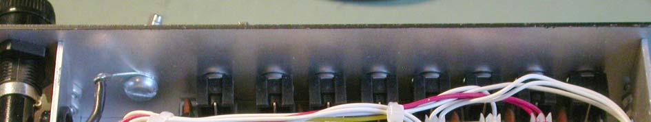
8 A Pin 1 Problem in Obsolete Equipment, and a Really Long Path to the Chassis Let s look behind the panel.


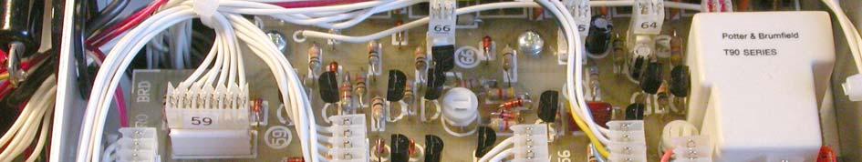
9 The Right Way A screw to connect the shields A classic RF pin 1 problem in a microphone
 Far too LONG - Inductance makes it high impedance 7.")

10 A classic RF pin 1 problem in a microphone Black wire goes to enclosure (good) Far too LONG - Inductance makes it high impedance MHz, 60 Ω at 850 MHz Orange wire goes to circuit board common Common impedance couples RF to circuit board The Pin 1 Problem in Microphones X


11 Pin 1 in Unbalanced Interfaces Some Classic Pin 1 Problems


12 How Does It Happen? Pin 1 of XL s go to chassis via circuit board and ¼ connectors (it s cheaper) XLR shell not connected to anything! RCA connectors not connected to chassis Testing for Pin 1 Problems
13 John Wendt s Hummer Test for Pin 1 Problems Drive between audio ground and chassis Listen to the output If you hear it, you have a problem RF Pin 1 Test Setup for Equipment 95% AM, 1 khz Drive between audio ground and chassis Listen to the output If you hear 1 khz, you have a problem


14 Pin 1 problems in a 4-channel mixer AM BC, 160 HF VHF Pin 1 problems in its replacement VHF HF Bands AM BC, 160


15 Pin 1 susceptibility of a much better product Sound Devices Mix Pre A Massive Pin 1 Problem in a Compressor HF Bands VHF

16 RF in the Shack is a Pin 1 Problem Nearly all ham gear has pin 1 problems Mic inputs Keying inputs Control inputs and outputs Nearly all computers have pin 1 problems Sound cards Serial ports Great Radio, Has Pin 1 Problems

17 Ten Tec Omni V


18 A Pin 1 Problem? Maybe Where are the Chassis Connections for this laptop s sound card? Hint: It isn t an audio connector shell! That metal is a shield, but not connected to connectors! And the cover is plastic too!
19 Where are the Chassis Connections for this laptop s sound card? Yes, it s the DB9 and DB25 shells! Consumer Cables are Antennas!
20 Consumer Cables are Antennas! Audio hookup cables Loudspeaker cables MATV Cables Computer Cables Video hookup cables Telephone cables Power cables A Textbook λ /2 Dipole
21 Battery Operated Equipment and its Cable can form a Dipole SPEAKER CABLE CIRCUIT BOARD EQUIPMENT CHASSIS It doesn t need to be an ideal quarter wave to work it will just be less efficient and its directivity may change! Basic Random Long Wire
22 Basic Random Long Wire AUDIO EQUIPMENT Example: 50kW on 720 khz (WGN) to test mics and input gear for RFI Equipment Setup Gas Generator
23 A poor RF ground (only the capacitance), so not much interference A better RF ground (the ground stake), so much more interference

24 This choke reduced the current, and thus the RFI Testing Microphones Equipment Setup Gas Generator
25 No RF ground for the mic, so no interference But when K9IKZ held the mic in his hand, some mics had RFI


26 Ferrites can block the current! Common Mode Coupling I/O wiring acts as long wire antenna Noise current flows lengthwise on wiring Noise Source Ferrites outside the box can Help a Lot!
27 Differential Mode Coupling I/O wiring is not band-pass filtered Noise is between + and terminals of wiring Trash Noise Source Trash Input Output Trash Ferrites can be used inside the box as part of low pass filters Poor Equipment Shielding Internal wiring radiates directly Noise Source Ferrites don t help at all!
28 Different sizes and shapes 2.4 o.d. 1 i.d. 1 i.d i.d. What s a Ferrite? A ceramic consisting of an iron oxide manganese-zinc 1-30 MHz (AM broadcast, hams) nickel-zinc 30 MHz-1 GHz (FM, TV, cell phones) Has permeability ( µ ) much greater than air Better path for magnetic flux than air Multiplies inductance of a wire passed through it Is increasingly lossy at higher frequencies Does not affect audio

29 A (too) simple equivalent circuit of a wire passing through a ferrite Complex Permeability µ = µ s + j µ s #61 Inductive Resistive 1 MHz 10 MHz 100 MHz 1 GHz

30 Complex Permeability µ = µ s + j µ s #78 Inductive Resistive 100 khz 1 MHz 10 MHz 100 MHz R s and X s vary with frequency! #43 1 MHz 10 MHz 100 MHz 1 GHz


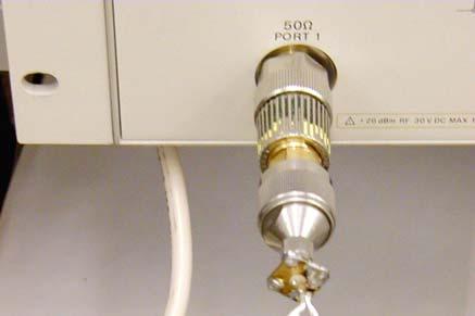
31 A Ferrite Optimized for UHF #61 1 MHz 10 MHz 100 MHz 1 GHz HP8753C w/hp85046a S-parameter Test Set (by my anonymous collaborator)


")

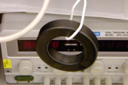
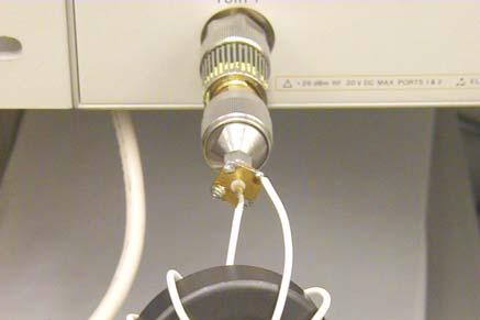
32 AEA CIA-HF Z N = N 2 * Z 1 Z for multi-turn chokes on a 2.4 toroid (Fair-Rite #78) 3 turns A material useful on the AM broadcast Band

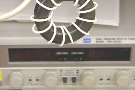
33 R S for multi-turn chokes on a 2.4 toroid R N = N 2 * R 1 #78 material useful on the AM broadcast Band X S for multi-turn chokes on a 2.4 toroid 5 turns X N = N 2. X 1 #78 material useful on the AM broadcast Band
34 5 turns Parallel Resonance! What Causes this Resonance? The ferrite material (called the mix ), and The physical dimensions of the ferrite core. The velocity of propagation within the ferrite establishes standing waves within the core V P = µε (that is, permeability * permittivity) Resonance occurs when the cross-section is a half-wavelength Frequency of the resonance depends on: Velocity of propagation (depends on the mix ) Dimensions of the cross-section of the flux path
35 Impedance of Multi-turn Chokes on # Toroid This One is Also Too Simple It is adequate at low frequencies, but look at high frequencies there is another resonance up there! L D and C D describe the dimensional resonance. R D accounts for the losses in the ferrite. We need a more complex equivalent circuit.
36 A Better Equivalent Circuit Ferrite Coil L C is the inductance of the coil C C is the stray capacitance of the coil R C is the resistance of the wire. L C and C C form the resonance that moves! Impedance of Multi-turn Chokes on # Toroid
37 Impedance of Chokes on # Toroid There s only one resonance here the coil Impedance of Multi-turn Chokes on # Toroid

38 Impedance of Chokes on # Toroid There s only one resonance here the coil Impedance of Multi-turn Chokes on # Toroid

39 Why no Dimensional Resonance? It s a different material! The first material, mix #78, was MnZn, while this one is NiZn V P in #43 is much higher, so dimensional resonance would occur at VHF rather than MF At VHF, there is so much loss that it damps the standing waves that produce dimensional resonance Impedance of Multi-turn Chokes on # Toroid

40 Data Sheets Show the Resonance Resonance Where s the Capacitance here?
41 Where s the Capacitance here? From the wire at one end of the choke to the wire at the other end, through the permittivity of the ferrite (it is a dielectric!) So How do We Use These Tools?

42 A Choke Applied to Audio Cable It s a voltage divider! The Choke can Resonate with the Antenna A short antenna looks capacitive X L can cancel some or all of X C ant Current will increase, unless R S limits it so, for effective suppression: R S should always be large!
43 Criteria for Good Suppression You May Not Need an Elephant Gun Most RFI detection is square law, so: A 10 db reduction in RF level reduces audible interference by 20 db
44 Resonance and Threshold Effect Example: Without the choke, the total antenna circuit is Ω (that is, capacitive) and we add a choke that is Ω (inductive), Z T = (150 j260) + (150 +j260) = 300 Ω Our choke has not reduced the current! Threshold Effect Additional R S will begin to reduce the current. Increasing R T to 425Ω (3 db) reduces detected RF by 6 db, and increasing R T to 600Ω (6 db) reduces detected RF by 12 db (assuming no change in X S ).
45 Threshold Effect For brute force suppression, the ferrite choke should add enough series R that the resulting Z is 2x the series Z of the antenna circuit without the choke. This reduces RF current by 6 db, and detected RF by 12 db. Very little suppression occurs until the added R is at least half of the starting Z. Criteria for Good Suppression Outside the box common-mode coupling In practical systems, the threshold is typically 300-1,000 ohms R S of the choke should be >1,000 ohms
 works for VHF A Multi-turn Choke (#31) is needed for lower")
46 Inside the Box For differential mode suppression, form a simple voltage divider Ferrite bead in series Capacitive (or resistive) load A few hundred ohms (or less) from the ferrite can be very effective Different Tools for Different Problems A Simple Bead (#43) works for VHF A Multi-turn Choke (#31) is needed for lower frequencies

47 A Really Nice New Mix Impedance of Chokes on # Toroid There s some dimensional resonance here, but it s mild, because there s so much loss

48 Impedance of Chokes on # Toroid Compare to #43 Good for AM BC and All HF Bands 2.4 o.d. Toroid #31

49 HF Bands Only # o.d. o.d. Toroid Toroid A Really Nice New Mix Fair-Rite #31 Greater suppression bandwidth one more octave one more ham band Much better HF suppression Equally good VHF suppression
50 Useful at VHF, but not below 30 MHz, because the Q is so high #61 But it makes a great transformer or balun! #61
51 #61 is great for HF baluns and transformers 2.4 o.d. How About Big Cables? 1 i.d. 1 i.d i.d.


52 If you can t easily remove the connector Biggest Clamp-On, #31 Sometimes you can t take the connector off
53 Suppression Guidelines Multiple chokes can be placed in series to cover multiple frequency ranges Z T = Z 1 + Z 2 The cable between the choke and the equipment can act as an antenna Always place the choke covering the higher frequency range nearest to the equipment Saturation Ferrites saturate at high power levels, reducing µ If both conductors of high power circuits are wound through core, the fields cancel, so only common mode current contributes to saturation This allows ferrites to be effective on loudspeaker and power wiring
54 These ferrites surround all three conductors of center-tapped single phase service, so don t saturate Temperature µ decreases with increasing temperature Suppression occurs with dissipation High power can result in heating
55 They can look alike, but be very different #43 #78 #61 #31 They re brittle!
56 Three Kinds of Ham RFI Interference from ham radio to other non-ham systems Interference to ham radio RF in the shack Basic Interference Mechanisms Pin 1 problems (both ways!) Fix them Chokes can help Coupled on input and output wiring Low pass filters Chokes can help Radiated directly to/from circuitry Shield equipment and ground the shield Good interior design to minimize loops Chokes cannot help
57 What Needs to Be Choked for Ham RFI to Home Entertainment Systems? Anything that can act as an antenna! RF coax lead-ins Video cables Audio cables Power cables This expensive loudspeaker cable makes equipment vulnerable to RFI Parallel wire (zip cord) has very poor RFI rejection


58 Twisted pair cables help equipment reject RFI #12 POC * is great loudspeaker cable! POC Plain Ordinary Copper Identifying RFI to the Ham Bands Check your own house first! Kill power to your house and listen with battery power With power restored, listen with a talkie that covers HF
59 Common RF Noise Sources at Home Anything Digital Anything with a microprocessor Anything with a clock (or oscillator) Anything with a motor or switch Computers Appliances Home Entertainment Power supplies Radios Other Notorious RFI Sources Electric fences Battery chargers for: Power tools (drills, etc.) Golf carts Lawn mowers Power supplies for: Low voltage lighting Computers Home electronics
60 Some Ethernet Birdies 3,511 khz 28,105 khz 10,106 khz 28,181 khz 10,122 khz 28,288 khz 14,030 khz 28,319 khz 21,052 khz 28,350 khz 28,014 khz 28,380 khz All frequencies are approximate
61 Ethernet Birdies Identify by killing power to router or hub Even when you fix your own, you may hear your neighbors (I did in Chicago) Methods of radiation The ethernet cable is a (long wire) antenna Direct radiation from the switch, hub, router, computer, and their power supplies Power supply cables are antennas
62 Ethernet Birdies Chokes will kill the common mode radiation (long wire) from the cable Use choke(s) on each cable (and each end of long cables) (Each end talks) Use multiple chokes if needed for wide frequency ranges, putting the highest frequency choke nearest to noise source Choke the power supply too! Power Line Filters Can Do More Harm Than Good Shunt capacitance couples noise to the ground wire The ground wire will act like an antenna


63 Noise Spectrum on Ground in a Typical Power System W6BX


64
65 RFI to Telephones Try ferrite chokes first Telephone wiring Power supply Common mode chokes K-Com bifilar-wound choke, about 15 mh A lot more choke than you can easily do yourself Acknowledgements Bill Whitlock Ron Steinberg (K9IKZ) Leo Irakliotis (KC9GLI) Neil Muncy (ex-w3wje) Fair-Rite Products
66 References E. C. Snelling, Soft Ferrites, Properties and Applications, CRC Press, 1969 E. C. Snelling and A. D. Giles, Ferrites for Inductors and Transformers, Research Study Press, 1983 Henry Ott, Noise Reduction Techniques in Electronic Systems, Wiley Interscience, 1988 Fair-Rite Products Catalog This 200-page catalog is a wealth of product data and applications guidance on practical ferrites. Ferroxcube Catalog and Applications Notes More online from another great manufacturer of ferrites. References Noise Susceptibility in Analog and Digital Signal Processing Systems, N. Muncy, JAES, June 1995 Radio Frequency Susceptibility of Capacitor Microphones, Brown/Josephson (AES Preprint 5720) Common Mode to Differential Mode Conversion in Shielded Twisted Pair Cables (Shield Current Induced Noise), Brown/Whitlock (AES Preprint 5747) Testing for Radio Frequency Common Impedance Coupling in Microphones and Other Audio Equipment, J. Brown (AES Preprint 5897) A Novel Method of Testing for Susceptibility of Audio Equipment to Interference from Medium and High Frequency Broadcast Transmitters, J. Brown (AES Preprint 5898)
67 References New Understandings of the Use of Ferrites in the Prevention and Suppression of RF Interference to Audio Systems, J. Brown (AES Preprint 6564) ARRL RFI Book Marv Loftness, AC Power Interference Handbook (ARRL) Understanding How Ferrites Can Prevent and Eliminate RF Interference to Audio Systems, J. Brown Self-published tutorial (on my website) Applications notes, tutorials, and my AES papers are on my website for free download RFI and Ferrites Jim Brown K9YC Audio Systems Group, Inc. Santa Cruz
Understanding and Eliminating RF Interference
 Understanding and Eliminating RF Interference Jim Brown K9YC Audio Systems Group, Inc. http://audiosystemsgroup.com Basic Interference Mechanisms Audio cables are antennas Pin 1 problems Shield-current-induced
RFI In Audio Systems Pin 1 Problems, Poor Shielding, and Poor Input/Output Filtering. The Heart of the Problem
 RFI In Audio Systems Pin 1 Problems, Poor Shielding, and Poor Input/Output Filtering Jim Brown Audio Systems Group, Inc. Chicago Santa Cruz jim@audiosystemsgroup.com The Heart of the Problem Audio equipment
New Understandings of the Use of Ferrites in the Prevention and Suppression of RF Interference to Audio Systems
 New Understandings of the Use of Ferrites in the Prevention and Suppression of RF Interference to Audio Systems Jim Brown Audio Systems Group, Inc. Chicago, IL, 60640 USA jim@audiosystemsgroup.com This
Coaxial Transmitting Chokes. Don t Bother Taking Notes
 Coaxial Transmitting Chokes Jim Brown K9YC Santa Cruz, CA http://audiosystemsgroup.com Don t Bother Taking Notes These slides (and a lot more) are at http://audiosystemsgroup.com\publish.htm 1 Why Do We
A Ham's Guide to RFI, Ferrites, Baluns, and Audio Interfacing. Chapter 1 Some Fundamentals
 A Ham's Guide to RFI, Ferrites, Baluns, and Audio Interfacing Revision 6 5 Dec 2016 by Jim Brown K9YC http://k9yc.com The basis of this tutorial is a combination of my engineering education, 60 years in
Locate and minimize those nasty RFI problems while transmitting or receiving on HF or VHF
 RFI in the Ham Shack - Tips and Traps Radio Frequency Interference Locate and minimize those nasty RFI problems while transmitting or receiving on HF or VHF Rick Lapp, KC2FD Typical RFI Problems while
An Introduction to Radio Frequency Interference
 An Introduction to Radio Frequency Interference Ron Hranac, N0IVN Member, ARRL EMC Committee ARRL Colorado Section Technical Specialist What is RFI? RFI is an abbreviation for radio frequency interference
Solving Electromagnetic Interference (EMI) with Ferrites
 with Ferrites") Solving Electromagnetic Interference (EMI) with Ferrites What are ferrites? How do ferrites help Suppress EMI? How to chose proper ferrite and component Material Characteristics Material and Core Selection
Solving Electromagnetic Interference (EMI) with Ferrites What are ferrites? How do ferrites help Suppress EMI? How to chose proper ferrite and component Material Characteristics Material and Core Selection
Killing RF Noise for Field Day and CQP. Jim Brown, K9YC
 Killing RF Noise for Field Day and CQP Jim Brown, K9YC The Fundamental Problem RF noise is generated inside equipment The wires inside equipment, and cables that interconnect equipment, are antennas, and
Application of Soft Ferrite Material: from EMC to RFID
 Application of Soft Ferrite Material: from EMC to RFID 26 April 2012 Alan Keenan Industrial Electronics GmbH in partnership with HF Technology & Fair-Rite Products Corp. www.fair-rite.com www.ie4u.eu Topics
Locate and minimize those nasty RFI problems while transmitting or receiving on HF or VHF
 RFI in the Ham Shack Tips, Tricks and Traps Radio Frequency Interference Locate and minimize those nasty RFI problems while transmitting or receiving on HF or VHF Rick Lapp, KC2FD rick@ricklapp.net Typical
Jacques Audet VE2AZX. Nov VE2AZX 1
 Jacques Audet VE2AZX VE2AZX@amsat.org Nov. 2006 VE2AZX 1 - REASONS FOR USING A BALUN - TYPES OF BALUNS - CHECK YOUR BALUN WITH AN SWR ANALYZER - MEASURING THE IMPEDANCE OF A NUMBER OF FERRITES - IMPEDANCE
Bob Brehm, AK6R Chief Engineer Palomar-Engineers.com
 Bob Brehm, AK6R Chief Engineer Palomar-Engineers.com EARS - October 2017 This presentation available on website Copyright 2013-2017 Palomar Engineers, Inc. Are you the SOURCE of RFI? IT S ALL YOUR FAULT
Bob Brehm, AK6R Chief Engineer Palomar-Engineers.com
 Bob Brehm, AK6R Chief Engineer Palomar-Engineers.com IDXC Visalia - April 2018 This presentation available on website Copyright 2013-2018 Palomar Engineers, Inc. Are you the SOURCE of RFI? IT S ALL YOUR
Wire Antennas For Limited Space
 Wire Antennas For Limited Space Jim Brown K9YC Santa Cruz, CA http://audiosystemsgroup.com Our Objectives Good Antennas Good efficiency Good predictable patterns Minimal noise pickup and RFI Inexpensive
Bob Brehm, AK6R Chief Engineer Palomar-Engineers.com. PVARC April Copyright 2016 Palomar Engineers, Inc.
 Bob Brehm, AK6R Chief Engineer Palomar-Engineers.com PVARC April 2016 Copyright 2016 Palomar Engineers, Inc. Causing Neighborhood RFI? IT S ALL YOUR FAULT WITH THAT BIG ANTENNA! Receiving RFI from Neighborhood?
ARNSW Balun Day. Balun construction
 ARNSW Balun Day Balun construction Typical Baluns All built from locally available components. Balun uses Most baluns are used to match the 50Ω output of a transceiver to an antenna. A centre fed dipole
Locating and Killing Receiver Interference. Gary Johnson, NA6O January, 2018
 Locating and Killing Receiver Interference Gary Johnson, NA6O January, 2018 1 Agenda Types of noise and interference Typical noise sources Finding the noise Noise mitigation Your rights per the FCC References
Bob Brehm, AK6R Chief Engineer Palomar-Engineers.com. Copyright 2015 Palomar Engineers, Inc.
 Bob Brehm, AK6R Chief Engineer Palomar-Engineers.com Copyright 2015 Palomar Engineers, Inc. RFI Workshop Objectives Review fundamentals of Common Mode Noise How ferrites work to suppress Common Mode noise
Ferrites for High Frequency Noise Suppression Chapter 9
 TMPST ngineering and Hardware Design Dr. Bruce C. abrielson, NC 1998 Ferrites for High Frequency Noise Suppression Chapter 9 Introduction The drive for higher speed devices and the proliferation of widespread
and Related Topics W7KVI, HARC Original: 3/26/16
 Baluns, Ununs, and Related Topics W7KVI, HARC Original: 3/26/16 This Presentation Informal & brisk - 52 slides (too many unless you re an enthusiast!) Discussion encouraged if not extensive, interrupt
Using Ferrites for High Frequency Noise Suppression
 Using Ferrites for High Frequency Noise Suppression Bruce C. abrielson, PhD Security ngineering Services PO Box 550, Chesapeake Beach, Maryland 20732 Introduction The drive for higher speed devices and
Chokes and Isolation Transformers For Receiving Antennas By Jim Brown K9YC 2018 by James W. Brown All rights reserved
 Chokes and Isolation Transformers For Receiving Antennas By Jim Brown K9YC 2018 by James W. Brown All rights reserved Why We Need Them A feedline must be grounded where it enters the shack-for lightning
COAXIAL TRANSMISSION LINE COMMON-MODE CURRENT
 COAXIAL TRANSMISSION LINE COMMON-MODE CURRENT Introduction Coaxial transmission lines are popular for their wide frequency bandwidth and high resistance to electromagnetic interference (EMI). Coax cables
Electromagnetic interference at the mains ports of an equipment
 Electromagnetic interference at the mains ports of an equipment Mircea Ion Buzdugan, Horia Bălan, Emil E. Simion, Tudor Ion Buzdugan Technical University from Cluj-Napoca, 15, Constantin Daicoviciu street,
MFJ-219/219N 440 MHz UHF SWR Analyzer TABLE OF CONTENTS
 MFJ-219/219N 440 MHz UHF SWR Analyzer TABLE OF CONTENTS Introduction...2 Powering The MFJ-219/219N...3 Battery Installation...3 Operation Of The MFJ-219/219N...4 SWR and the MFJ-219/219N...4 Measuring
The design of Ruthroff broadband voltage transformers M. Ehrenfried G8JNJ
 The design of Ruthroff broadband voltage transformers M. Ehrenfried G8JNJ Introduction I started investigating balun construction as a result of various observations I made whilst building HF antennas.
Categorized by the type of core on which inductors are wound:
 Inductors Categorized by the type of core on which inductors are wound: air core and magnetic core. The magnetic core inductors can be subdivided depending on whether the core is open or closed. Equivalent
Antenna Design for FM-02
 Antenna Design for FM-02 I recently received my FM-02 FM transmitter which I purchased from WLC. I researched the forum on what antennas where being used by the DIY community and found a nice write-up
SCIN. Shield Current Induced Noise. Causes and Solutions. Random Thoughts from Chicago
 Random Thoughts from Chicago SCIN Shield Current Induced Noise by Jim Brown Causes and Solutions My last two columns have focused on pin 1 problems as an open door for RF into audio equipment. But RF can
How to Blow Up Your Balun
 How to Blow Up Your Balun (and other things too ) By Dean Straw, N6BV Sea-Pac June 7, 2014 Photos courtesy Jim Brown, K9YC 1 This is What I Intend to do Today I will examine stresses placed on common-mode
What is an Inductor? Token Electronics Industry Co., Ltd. Version: January 16, Web:
 Version: January 16, 2017 What is an Inductor? Web: www.token.com.tw Email: rfq@token.com.tw Token Electronics Industry Co., Ltd. Taiwan: No.137, Sec. 1, Zhongxing Rd., Wugu District, New Taipei City,
Milton Keynes Amateur Radio Society (MKARS)
") Milton Keynes Amateur Radio Society (MKARS) Intermediate Licence Course Feeders Antennas Matching (Worksheets 31, 32 & 33) MKARS Intermediate Licence Course - Worksheet 31 32 33 Antennas Feeders Matching
Milton Keynes Amateur Radio Society (MKARS) Intermediate Licence Course Feeders Antennas Matching (Worksheets 31, 32 & 33) MKARS Intermediate Licence Course - Worksheet 31 32 33 Antennas Feeders Matching
Design Considerations
 Design Considerations Ferrite beads provide a simple, economical method for attenuating high frequency noise or oscillations. By slipping a bead over a wire, a RF choke or suppressor is produced which
WHY YOU NEED A CURRENT BALUN
 HF OPERATORS WHY YOU NEED A CURRENT BALUN by John White VA7JW NSARC HF Operators 1 What is a Balun? A BALUN is a device typically inserted at the feed point of a dipole-like antenna wire dipoles, Yagi
db = 10 log10 (P1/P2) where P1 and P2 are two power levels
 where P1 and P2 are two power levels") A Quick Introduction to Decibels (db) Unit is the Bel: named after A.G. Bell who devised it for his work with deafness and audio sound levels. Now used for all frequencies of AC power. Decibel (db): -1
A Quick Introduction to Decibels (db) Unit is the Bel: named after A.G. Bell who devised it for his work with deafness and audio sound levels. Now used for all frequencies of AC power. Decibel (db): -1
SOME USES FOR RF1,RF5 and VA1 ANALYSTS. SWR Measurement
 SOME USES FOR RF1,RF5 and VA1 ANALYSTS THE HANDIEST INSTRUMENTS IN DECADES! When you put up an antenna in the the old days, it could be a real struggle. The only way to tell if it was tuned to the right
EMI AND BEL MAGNETIC ICM
 EMI AND BEL MAGNETIC ICM ABSTRACT Electromagnetic interference (EMI) in a local area network (LAN) system is a common problem that every LAN system designer faces, and it is a growing problem because the
MFJ-249B HF/VHF SWR ANALYZER
 TABLE OF CONTENTS MFJ-249B... 2 Introduction... 2 Powering The MFJ-249B... 3 Battery Installation... 3 Alkaline Batteries... 3 NiCd Batteries... 4 Power Saving Mode... 4 Operation Of The MFJ-249B...5 SWR
Common myths, fallacies and misconceptions in Electromagnetic Compatibility and their correction.
 Common myths, fallacies and misconceptions in Electromagnetic Compatibility and their correction. D. A. Weston EMC Consulting Inc 22-3-2010 These are some of the commonly held beliefs about EMC which are
Basic Wire Antennas. Part II: Loops and Verticals
 Basic Wire Antennas Part II: Loops and Verticals A loop antenna is composed of a single loop of wire, greater than a half wavelength long. The loop does not have to be any particular shape. RF power can
What is a BALUN or UNUN:
 What is a BALUN or UNUN: A device to connect different types of antennas to various feed lines. Can transform impedances, choke common mode or change balanced to unbalanced BALUN Balanced to Unbalanced
The Amazing MFJ 269 Author Jack Tiley AD7FO
 The Amazing MFJ 269 Author Jack Tiley AD7FO ARRL Certified Emcomm and license class Instructor, Volunteer Examiner, EWA Technical Coordinator and President of the Inland Empire VHF Club What Can be Measured?
Device Interconnection
 Device Interconnection An important, if less than glamorous, aspect of audio signal handling is the connection of one device to another. Of course, a primary concern is the matching of signal levels and
The Ins and Outs of Audio Transformers. How to Choose them and How to Use them
 The Ins and Outs of Audio Transformers How to Choose them and How to Use them Steve Hogan Product Development Engineer, Jensen Transformers 1983 1989 Designed new products and provided application assistance
ROD ANTENNA TESTING Complete article download from: EMI TESTING. Basic RE102 test (2-30 MHz)
") ROD ANTENNA TESTING Complete article download from: http://stevejensenconsultants.com/rod_ant.pdf EMI TESTING Steve Jensen Steve Jensen Consultants Inc. Sept. 26, 2005 Applicable for DO-160 sec. 21 and
ROD ANTENNA TESTING Complete article download from: http://stevejensenconsultants.com/rod_ant.pdf EMI TESTING Steve Jensen Steve Jensen Consultants Inc. Sept. 26, 2005 Applicable for DO-160 sec. 21 and
GLOSSARY OF TERMS FLUX DENSITY:
 ADSL: Asymmetrical Digital Subscriber Line. Technology used to transmit/receive data and audio using the pair copper telephone lines with speed up to 8 Mbps. AMBIENT TEMPERATURE: The temperature surrounding
Killing Receive Noise. Jim Brown K9YC
 Killing Receive Noise Jim Brown K9YC k9yc@arrl.net Don t Bother Taking Notes These slides and the tutorial from National Contest Journal are on my website http://k9yc.com/publish.htm Two Major Kinds of
4/30/2012. General Class Element 3 Course Presentation. Circuit CoCircuit Componentsmponents. Subelement G6. 3 Exam Questions, 3 Groups
 General Class Element 3 Course Presentation ti ELEMENT 3 SUB ELEMENTS General Licensing Class Subelement G6 Circuit Components 3 Exam Questions, 3 Groups G1 Commission s Rules G2 Operating Procedures G3
Antenna? What s That? Chet Thayer WA3I
 Antenna? What s That? Chet Thayer WA3I Space: The Final Frontier Empty Space (-Time) Four dimensional region that holds everything Is Permeable : It requires energy to set up a magnetic field within it.
Pro Audio Eng PAE-Kx33 AC Power Supply
 Pro Audio Eng PAE-Kx33 AC Power Supply for the Elecraft KX3 Transceiver (and others w/ adapter) Owner s Manual Rev 1.5 February 20, 2015 Thank you for purchasing the PAE-Kx33 AC Power Supply. We originally
1) Transmission Line Transformer a. First appeared on the scene in 1944 in a paper by George Guanella as a transmission line transformer, the 1:1
 Transmission Line Transformer a. First appeared on the scene in 1944 in a paper by George Guanella as a transmission line transformer, the 1:1") 1) Transmission Line Transformer a. First appeared on the scene in 1944 in a paper by George Guanella as a transmission line transformer, the 1:1 Guanella Balun is the basic building Balun building block.
1) Transmission Line Transformer a. First appeared on the scene in 1944 in a paper by George Guanella as a transmission line transformer, the 1:1 Guanella Balun is the basic building Balun building block.
11 Myths of EMI/EMC ORBEL.COM. Exploring common misconceptions and clarifying them. MYTH #1: EMI/EMC is black magic.
 11 Myths of EMI/EMC Exploring common misconceptions and clarifying them By Ed Nakauchi, Technical Consultant, Orbel Corporation What is a myth? A myth is defined as a popular belief or tradition that has
Fundamentals of Antennas. Prof. Ely Levine
 Fundamentals of Antennas Prof. Ely Levine levineel@zahav.net.il 1 Chapter 3 Wire Antennas 2 Types of Antennas 3 Isotropic Antenna Isotropic radiator is the simplest antenna mathematically Radiates all
Page 1The VersaTee Vertical 60m, 80m Modular Antenna System Tutorial Manual
 Page 1The VersaTee Vertical 60m, 80m Modular Antenna System Tutorial Manual by: Lou Rummel, KE4UYP Page 1 In the world of low band antennas this antenna design is unique in many different ways. 1. It is
PCB Design Guidelines for Reduced EMI
 PCB Design Guidelines for Reduced EMI Guided By: Prof. Ruchi Gajjar Prepared By: Shukla Jay (13MECE17) Outline Power Distribution for Two-Layer Boards Gridding Power Traces on Two-Layer Boards Ferrite
Bob Brehm, AK6R Chief Engineer Palomar-Engineers.com. Copyright 2014 Palomar Engineers, Inc.
 Bob Brehm, AK6R Chief Engineer Palomar-Engineers.com Copyright 2014 Palomar Engineers, Inc. RFI Workshop Objectives Learn fundamentals of RFI How ferrites work to suppress RFI How to use ferrite kits to
A Transmatch for Balanced or Unbalanced Lines
 A Transmatch for Balanced or Unbalanced Lines Most modern transmitters are designed to operate into loads of approximately 50 Ω. Solid-state transmitters produce progressively lower output power as the
Chapter 12: Transmission Lines. EET-223: RF Communication Circuits Walter Lara
 Chapter 12: Transmission Lines EET-223: RF Communication Circuits Walter Lara Introduction A transmission line can be defined as the conductive connections between system elements that carry signal power.
A TRANSMISSION LINE BALANCE TEST METER
 by Lloyd Butler VK5BR with modifications by Phil Storr VK5SRP. Here is a simple meter to check the balance of currents running in the two legs of a transmission line. It can be used to check the balance
Finding and Killing Receive Noise. Jim Brown K9YC
 Finding and Killing Receive Noise Jim Brown K9YC k9yc@arrl.net Don t Bother Taking Notes These slides and the tutorial from National Contest Journal are on my website http://k9yc.com/publish.htm Two Major
application note Philips Magnetic Products Cable Shielding Philips Components
 application note Cable Shielding Philips Components Cable Shielding Contents Introduction 3 EMI suppression and cable shielding with ferrites 4 Ferrite selection 6 Material properties 7 Ferrite core and
"Natural" Antennas. Mr. Robert Marcus, PE, NCE Dr. Bruce C. Gabrielson, NCE. Security Engineering Services, Inc. PO Box 550 Chesapeake Beach, MD 20732
 Published and presented: AFCEA TEMPEST Training Course, Burke, VA, 1992 Introduction "Natural" Antennas Mr. Robert Marcus, PE, NCE Dr. Bruce C. Gabrielson, NCE Security Engineering Services, Inc. PO Box
The shunt capacitor is the critical element
 Accurate Feedthrough Capacitor Measurements at High Frequencies Critical for Component Evaluation and High Current Design A shielded measurement chamber allows accurate assessment and modeling of low pass
Inductors & Resonance
 Inductors & Resonance The Inductor This figure shows a conductor carrying a current. A magnetic field is set up around the conductor as concentric circles. If a coil of wire has a current flowing through
ELECTROMAGNETIC COMPATIBILITY HANDBOOK 1. Chapter 8: Cable Modeling
 ELECTROMAGNETIC COMPATIBILITY HANDBOOK 1 Chapter 8: Cable Modeling Related to the topic in section 8.14, sometimes when an RF transmitter is connected to an unbalanced antenna fed against earth ground
Using Ferrite Beads Keep RF Out of TV Sets, Telephones, VCR's Burglar Alarms and other Electronic Equipment
 Using Ferrite Beads Keep RF Out of TV Sets, Telephones, VCR's Burglar Alarms and other Electronic Equipment RFI and TVI have been with us for a long time. Now we have microwave ovens, VCR's and many other
Maximize power transfer Reduce feed line loss (if match is at the antenna) Make transmitters happy!
 Make transmitters happy!") Ward Silver - NØAX Impedance = ratio of voltage to current Mechanical analogies Mechanical impedance = ratio of torque to rate of rotation Vehicle transmission is an impedance converter Transfers power
Ward Silver - NØAX Impedance = ratio of voltage to current Mechanical analogies Mechanical impedance = ratio of torque to rate of rotation Vehicle transmission is an impedance converter Transfers power
Corcom Product Guide. Introduction
 Introduction Corcom brand SignalSentry filtered modular jack series product combines different levels of filtering with and modular jacks to solve signal line noise problems and crosstalk. Corcom brand
Chapter 12 Digital Circuit Radiation. Electromagnetic Compatibility Engineering. by Henry W. Ott
 Chapter 12 Digital Circuit Radiation Electromagnetic Compatibility Engineering by Henry W. Ott Forward Emission control should be treated as a design problem from the start, it should receive the necessary
Optimizing Your Stations Performance
 Optimizing Your Stations Performance A few hints / techniques, recommendations for getting the most RF out to the Antenna from your HF, VHF / UHF station. Tonights Presenters: Doug Theriault NO1D John
General Licensing Class Circuits
 General Licensing Class Circuits Valid July 1, 2011 Through June 30, 2015 1 Amateur Radio General Class Element 3 Course Presentation ELEMENT 3 SUB-ELEMENTS (Groupings) Your Passing CSCE Your New General
A statistical survey of common-mode noise
 A statistical survey of common-mode noise By Jerry Gaboian Characterization Engineer, High Performance Linear Department Introduction In today s high-tech world, one does not have to look very far to find
A short, off-center fed dipole for 40 m and 20 m by Daniel Marks, KW4TI
 A short, off-center fed dipole for 40 m and 20 m by Daniel Marks, KW4TI Version 2017-Nov-7 Abstract: This antenna is a 20 to 25 foot long (6.0 m to 7.6 m) off-center fed dipole antenna for the 20 m and
Reducing Motor Drive Radiated Emissions
 Volume 2, Number 2, April, 1996 Application Note 107 Donald E. Fulton Reducing Motor Drive Radiated Emissions Introduction This application note discusses radiated emissions (30 Mhz+) of motor drives and
Differential-Mode Emissions
 Differential-Mode Emissions In Fig. 13-5, the primary purpose of the capacitor C F, however, is to filter the full-wave rectified ac line voltage. The filter capacitor is therefore a large-value, high-voltage
1 of 11 30/08/2011 8:50 AM
 1 of 11 30/08/2011 8:50 AM All Ferrite Beads Are Not Created Equal - Understanding the Importance of Ferrite Bead Material Behavior August 2010 Written by Chris Burket, TDK Corporation A common scenario:
PRINCIPLES OF COMMUNICATION SYSTEMS. Lecture 1- Introduction Elements, Modulation, Demodulation, Frequency Spectrum
 PRINCIPLES OF COMMUNICATION SYSTEMS Lecture 1- Introduction Elements, Modulation, Demodulation, Frequency Spectrum Topic covered Introduction to subject Elements of Communication system Modulation General
Ferrites VE3KL A spinning electron works like a gyroscope Gyro frequency tells all. 1/28/2017 David Conn VE3KL 1
 Ferrites VE3KL A spinning electron works like a gyroscope Gyro frequency tells all J Bo m 1/28/2017 David Conn VE3KL 1 Presentation Outline Review of magnetic terms: H, B, M and Gyro frequency Ferrite
4,000Ω +j 300Ω sometimes cancelling, but RS values always adding.
 A New Choke Cookbook for the 160 10M Bands Using Fair-Rite #31 2.4-in o.d. (2631803802) and 4-in o.d. (2631814002) Toroids 2018 by James W. Brown All Rights Reserved Introduction: Common mode chokes are
Bob Brehm, AK6R Chief Engineer Palomar-Engineers.com. Copyright 2014 Palomar Engineers, Inc.
 Bob Brehm, AK6R Chief Engineer Palomar-Engineers.com Copyright 2014 Palomar Engineers, Inc. What is RFI? Radio Frequency Interference/Electromagnetic Interference (RFI/EMI) at radio frequencies A radio
Components. Véronique Beauvois, Ir Copyright 2015 Véronique Beauvois, ULg
 Components Véronique Beauvois, Ir. 2015-2016 1 Specific components Solutions Essential rules Technical vs. economical constraints Global concept / Early stage If not, the risk is additional cost (3 to
Freescale Semiconductor, I
 Order this document by /D Noise Reduction Techniques for Microcontroller-Based Systems By Imad Kobeissi Introduction With today s advancements in semiconductor technology and the push toward faster microcontroller
Bob Brehm, AK6R Chief Engineer Palomar-Engineers.com
 Bob Brehm, AK6R Chief Engineer Palomar-Engineers.com LAKESIDE - October 2017 This presentation available on website Copyright 2013-2017 Palomar Engineers, Inc. End Fed Workshop Topics Popular End Fed Antenna
Line Level Cables in the Automotive Environment
 Line Level Cables in the Automotive Environment Dan Wiggins Adire Audio http://www.adireaudio.com The automotive environment can be a very difficult one for line level cables (RCA cables). High voltage
Adjust Antenna Tuners Antenna Measurements Capacitor Measurement Measure Feed Point Impedance Measure Ground Loss Inductor Measurement
 The Micro908 antenna analyzer is an extremely useful instrument to have around the ham shack or homebrewer s workbench. This section describes the basic uses, as well as some advanced techniques for which
Presented by Joanna Hill
 Santa Clara IEEE EMC Chapter meeting April 9, 2013 Dorothy we're not in Kansas any more, we are in Impedance land. Oh my! Presented by Joanna Hill Cell 248-765-3599 jhill28590@comcast.net Welcome to Impedance
Radio Frequency Interference! Al Penney VO1NO
 Radio Frequency Interference! RFI and EMI Radio Frequency Interference (RFI) Interference to a receiver caused by actual signals, only one of which is desired. Caused by harmonics, mixing, images, or poor
APPLICATION NOTE. System Design for RF Immunity
 APPLICATION NOTE System Design for RF Immunity Audio Codec Application Note Rev1.0 Page 1 of 6 March 2008 With the growth of the portable electronic devices industry, radiated RF fields and potential interference
Technician License. Course
 Technician License Course Technician License Course Chapter 4 Lesson Plan Module - 10 Practical Antennas The Dipole Most basic antenna The Dipole Most basic antenna The Dipole Total length is ½ wavelength
4/29/2012. General Class Element 3 Course Presentation. Ant Antennas as. Subelement G9. 4 Exam Questions, 4 Groups
 General Class Element 3 Course Presentation ti ELEMENT 3 SUB ELEMENTS General Licensing Class Subelement G9 Antennas and Feedlines 4 Exam Questions, 4 Groups G1 Commission s Rules G2 Operating Procedures
Lecture 4. Maximum Transfer of Power. The Purpose of Matching. Lecture 4 RF Amplifier Design. Johan Wernehag Electrical and Information Technology
 Johan Wernehag, EIT Lecture 4 RF Amplifier Design Johan Wernehag Electrical and Information Technology Design of Matching Networks Various Purposes of Matching Voltage-, Current- and Power Matching Design
T/R Switches, Baluns, and Detuning Elements in MRI RF coils Xiaoyu Yang 1,2, Tsinghua Zheng 1,2 and Hiroyuki Fujita 1,2,3.
 T/R Switches, Baluns, and Detuning Elements in MRI RF coils Xiaoyu Yang 1,2, Tsinghua Zheng 1,2 and Hiroyuki Fujita 1,2,3 1 Department of Physics, Case Western Reserve University 2 Department of Radiology,
Bob Brehm, AK6R Chief Engineer Palomar-Engineers.com
 Bob Brehm, AK6R Chief Engineer Palomar-Engineers.com HAMCON 2017 - September 2017 This presentation available on website Copyright 2013-2017 Palomar Engineers, Inc. End Fed Workshop Topics Popular End
Common myths, fallacies and misconceptions in Electromagnetic Compatibility and their correction.
 Common myths, fallacies and misconceptions in Electromagnetic Compatibility and their correction. D. A. Weston EMC Consulting Inc 15-3-2013 1) First topic an introduction These are some of the commonly
Understanding the Importance of Ferrite Bead Material Behavior
 Magazine August 2010 All ferrite beads are not created equal Understanding the Importance of Ferrite Bead Material Behavior by Chris T. Burket, TDK Corporation A common scenario: A design engineer inserts
HF Wire Antennas, EMI Contest Stations. WCARC November 2016 VE3KL
 HF Wire Antennas, EMI Contest Stations WCARC November 2016 VE3KL Introduction A Top Down View of a Radio Station(s) 1. Wire Antenna Design...Ideas needed.. 2. Dipoles and Unwanted Radiation (EMI) 3. A
630 metres (or Bust!)
") 630 metres (or Bust!) Amateur Radio on Long Wave CW Calling frequency 474.2kHz WSPR: 474.2 khz USB dial frequency, audio between 1400 1600 Hz JT9: 474.2 khz dial frequency, audio between 1000 1350 Hz (can
630 metres (or Bust!) Amateur Radio on Long Wave CW Calling frequency 474.2kHz WSPR: 474.2 khz USB dial frequency, audio between 1400 1600 Hz JT9: 474.2 khz dial frequency, audio between 1000 1350 Hz (can
Analogue circuit design for RF immunity
 Analogue circuit design for RF immunity By EurIng Keith Armstrong, C.Eng, FIET, SMIEEE, www.cherryclough.com First published in The EMC Journal, Issue 84, September 2009, pp 28-32, www.theemcjournal.com
Bob Brehm, AK6R Chief Engineer Palomar-Engineers.com. Copyright 2014 Palomar Engineers, Inc.
 Bob Brehm, AK6R Chief Engineer Palomar-Engineers.com Copyright 2014 Palomar Engineers, Inc. What is RFI? Radio Frequency Interference/Electromagnetic Interference (RFI/EMI) at radio frequencies A radio