Maximize power transfer Reduce feed line loss (if match is at the antenna) Make transmitters happy!
|
|
|
- Jewel Thomasine Owen
- 5 years ago
- Views:
Transcription
1 Ward Silver - NØAX
2 Impedance = ratio of voltage to current Mechanical analogies Mechanical impedance = ratio of torque to rate of rotation Vehicle transmission is an impedance converter Transfers power from the engine to the wheels Change combination of torque and rate of rotation Maximize power transfer Reduce feed line loss (if match is at the antenna) Make transmitters happy! October
3 Elevated SWR in a feed line increases loss More trips through the line for reflected waves Raises peak voltage dielectric loss Raises peak current resistance loss (I 2 R) Unhappy transmitters reduce power Can reduce receive sensitivity Reduced SWR bandwidth October
4 Elevated SWR in a feed line increases loss More trips through the line for reflected waves Raises peak voltage dielectric loss Raises peak current resistance loss (I 2 R) Unhappy transmitters reduce power Can reduce receive sensitivity Reduced SWR bandwidth DOES NOT Increase RFI or noise pickup Change antenna pattern Cause bad breath or embarrass your mother October
5 For a great video explaining SWR AT&T Archives on YouTube Similarities in Wave Behavior Very visual, simple math Excellent introduction to Transmission Line concepts October
6 Different optimum impedances in air-insulated lines for Loss, power-handling, peak voltage, etc 30 ohms optimizes power handling 70 ohms optimizes loss 50 ohms became common in the 1930s Availability of standard tubing sizes and plastic 50 ohms split the difference of 30 and 70 ohms Good compromise performance WWII and polyethylene made 50 ohms the de-facto standard with good power handling and loss October
7 Resistive or Reactive matching? Resistive is cheap but dissipates power Reactive is efficient but frequency sensitive Resistive examples 50-ohm attenuator Tee and Pi-network pads Parallel and series resistors TFTD folded dipole with resistive center-loading Really long runs of old coax October
8 Transformers October
9 Broadband transformers Audio and modulation transformers Ferrite and powdered-iron cores Transform voltage/current ratio V sec / I sec = Z sec and V pri / I pri = Z pri Z sec / Z pri = n 2 If n = 2, Z ratio = 4; n = 3, Z ratio = 9, etc October

10 Broadband transformers October
11 October
12 Abbreviation of balanced to unbalanced Balanced both conductors symmetric with respect to ground (open-wire line, free-space dipole, etc) Unbalanced conductors asymmetric with respect to ground (coaxial cable, single-wire lines or systems with enclosure return, ground plane verticals) ANY device that isolates balanced and unbalanced systems while transferring power between them performs the balun function! Unun operates between two unbalanced systems October
 Ferrite bead and coiled-coax choke baluns An impedance transformer is not necessarily a balun and vice versa!")
13 Current balun forces equal currents in load terminals Voltage balun forces equal voltages in load terminals Guanella and Ruthroff transmission line baluns Resonant transmission line sleeve baluns (λ/4, λ/2) Ferrite bead and coiled-coax choke baluns An impedance transformer is not necessarily a balun and vice versa! October
14 October
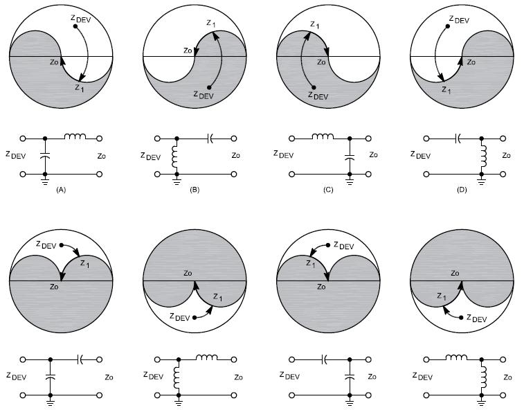
15 Reactive meaning using L s and C s Network is just a fancy name for circuit L network Pi (and Pi-L) network and T-network Tapped-coil LC tank circuit and shunt-l Networks can be high-pass (series-c) or low-pass (series-l) Usually designed to work at just one frequency October
16 Two components: L-C, L-L, or C-C Transforms high-to-low depending on the orientation of the components If it doesn t work, turn it around! Series-C is a high-pass network Series-L is a low-pass network October

17 October

18 Two L-networks back to back Allows more gradual impedance change Wider bandwidth and a larger impedance ratio Used in tube amplifiers Pi-L network adds one additional L in series with R 2 October
19 Typical of most antenna tuners sold today Also can be thought of as a pair of L networks Usually in high-pass configuration because variable capacitors are cheaper than variable inductors October

20 Fun tuner simulator by W9CF - fermi.la.asu.edu/w9cf/tuner/tuner.html October

21 Synchronous transformers Quarter-wave or Q- section 1/12 th -wave sections Useful for 50-to-75 ohm matching Single-frequency match October
22 Structures and transmission line techniques Mount on the antenna or are part of the antenna feed point assembly Require adjustment at the antenna One-band matching October
23 Originally for open-wire to dipole Center feed point impedance ohms End impedance several kohms Find point with open-wire impedance October

24 Builds on delta match Made for balanced transmission line Constructs a transmission line on each side Has also been modeled as a folded dipole October
25 One-half of a T match Allows driven element to be grounded at lowimpedance point (the center) Capacitor usually constructed of insulated wire inside tube October

26 Also called hairpin match Requires insulated driven element Center of symmetrical hairpin can be grounded Transforms impedance up like an L network October
27 ARRL Handbook and ARRL Antenna Book Antenna Book software TLW, MATCH, etc ARRL Guide to Antenna Tuners by W1ZR ARRL Online Archives of QST, QEX, NCJ Ham Radio also searchable, not archived Antenna Compendiums, Vol 1-8 Hands-On Radio by NØAX in QST October
28 Transmission Line Transformers J. Sevick, W2FMI (SK) Reflections I, II, or III W. Maxwell, W2DU (SK) LB Cebik W4RNL (SK) - now available through antennex.com online or on CD-ROM Online calculators (RF Café, Microwaves 101) HAMCALC package by VE3ERP (CQ website) Textbooks that are available on-line Radio Engineering Terman Radio Antenna Engineering Laport See also Antenna Fundamentals chapter of ARRL Antenna Book October
29 October
COAXIAL TRANSMISSION LINE COMMON-MODE CURRENT
 COAXIAL TRANSMISSION LINE COMMON-MODE CURRENT Introduction Coaxial transmission lines are popular for their wide frequency bandwidth and high resistance to electromagnetic interference (EMI). Coax cables
Antennas 101 Don t Be a 0.97 db Weakling! Ward Silver NØAX
 Antennas 101 Don t Be a 0.97 db Weakling! Ward Silver NØAX Overview Antennas 101 2 Overview Basic Antennas: Ground Plane / Dipole How Gain and Nulls are Formed How Phased Arrays Work How Yagis Work (simplified)
What is a BALUN or UNUN:
 What is a BALUN or UNUN: A device to connect different types of antennas to various feed lines. Can transform impedances, choke common mode or change balanced to unbalanced BALUN Balanced to Unbalanced
Antennas and Stuff. John Kernkamp WB4YJT
 Antennas and Stuff John Kernkamp WB4YJT John Kraus W8JK June 28, 1910 - July 18, 2004 Invented the helical antenna, the corner reflector, and the W8JK End-Fire array. In 1950 designed and built the Big
Jacques Audet VE2AZX. Nov VE2AZX 1
 Jacques Audet VE2AZX VE2AZX@amsat.org Nov. 2006 VE2AZX 1 - REASONS FOR USING A BALUN - TYPES OF BALUNS - CHECK YOUR BALUN WITH AN SWR ANALYZER - MEASURING THE IMPEDANCE OF A NUMBER OF FERRITES - IMPEDANCE
Free ferrite from TV sets in BALUN use
 Free ferrite from TV sets in BALUN use JK De Marco, PY2WM 18/jan/2006, revised on 2/April/2009 After an article by Ian White, G3SEK, in RadCom magazine, suggesting the use of ferrite removed from deflection
MFJ-219/219N 440 MHz UHF SWR Analyzer TABLE OF CONTENTS
 MFJ-219/219N 440 MHz UHF SWR Analyzer TABLE OF CONTENTS Introduction...2 Powering The MFJ-219/219N...3 Battery Installation...3 Operation Of The MFJ-219/219N...4 SWR and the MFJ-219/219N...4 Measuring
and Related Topics W7KVI, HARC Original: 3/26/16
 Baluns, Ununs, and Related Topics W7KVI, HARC Original: 3/26/16 This Presentation Informal & brisk - 52 slides (too many unless you re an enthusiast!) Discussion encouraged if not extensive, interrupt
The Fabulous Dipole. Ham Radio s Most Versatile Antenna
 The Fabulous Dipole Ham Radio s Most Versatile Antenna 1 What is a Dipole? Gets its name from its two halves One leg on each side of center Each leg is the same length It s a balanced antenna The voltages
ECE Microwave Engineering
 ECE 5317-6351 Microwave Engineering Adapted from notes by Prof. Jeffery T. Williams Fall 2018 Prof. David R. Jackson Dept. of ECE Notes 4 Transmission Lines Part 3: Baluns 1 Baluns Baluns are used to connect
WCARES NEEDS YOU! CONSIDER MAKING A TECHNICAL PRESENTATION AT AN UPCOMING CHEW & CHAT MEETING LEARN SOMETHING NEW AND PRESENT
 WCARES NEEDS YOU! CONSIDER MAKING A TECHNICAL PRESENTATION AT AN UPCOMING CHEW & CHAT MEETING SHARE WHAT YOU KNOW LEARN SOMETHING NEW AND PRESENT IT CONTACT TIM AD4CJ AD4CJ@arrl.net 1 Transmission Line
1) Transmission Line Transformer a. First appeared on the scene in 1944 in a paper by George Guanella as a transmission line transformer, the 1:1
 Transmission Line Transformer a. First appeared on the scene in 1944 in a paper by George Guanella as a transmission line transformer, the 1:1") 1) Transmission Line Transformer a. First appeared on the scene in 1944 in a paper by George Guanella as a transmission line transformer, the 1:1 Guanella Balun is the basic building Balun building block.
1) Transmission Line Transformer a. First appeared on the scene in 1944 in a paper by George Guanella as a transmission line transformer, the 1:1 Guanella Balun is the basic building Balun building block.
Feed Line Currents for Neophytes.
 Feed Line Currents for Neophytes. This paper discusses the sources of feed line currents and the methods used to control them. During the course of this paper two sources of feed line currents are discussed:
Bob Brehm, AK6R Chief Engineer Palomar-Engineers.com
 Bob Brehm, AK6R Chief Engineer Palomar-Engineers.com HAMCON 2017 - September 2017 This presentation available on website Copyright 2013-2017 Palomar Engineers, Inc. End Fed Workshop Topics Popular End
The design of Ruthroff broadband voltage transformers M. Ehrenfried G8JNJ
 The design of Ruthroff broadband voltage transformers M. Ehrenfried G8JNJ Introduction I started investigating balun construction as a result of various observations I made whilst building HF antennas.
Bob Brehm, AK6R Chief Engineer Palomar-Engineers.com
 Bob Brehm, AK6R Chief Engineer Palomar-Engineers.com LAKESIDE - October 2017 This presentation available on website Copyright 2013-2017 Palomar Engineers, Inc. End Fed Workshop Topics Popular End Fed Antenna
ARNSW Balun Day. Balun construction
 ARNSW Balun Day Balun construction Typical Baluns All built from locally available components. Balun uses Most baluns are used to match the 50Ω output of a transceiver to an antenna. A centre fed dipole
Portable Vertical Antenna for 75m & 40m
 Portable Vertical Antenna for 75m & 40m BOXBORO August 2012 Jacques VE2AZX Web: ve2azx.net 1 Objectives 1- Portable Antenna for 75m et 40m 2- Low radiation angle for DX 3- Efficient 4- Easy to install.
Investigation of the Double-Y Balun for Feeding Pulsed Antennas
 Proceedings of the SPIE, Vol. 5089, April 2003 Investigation of the Double-Y Balun for Feeding Pulsed Antennas Jaikrishna B. Venkatesan a and Waymond R. Scott, Jr. b Georgia Institute of Technology Atlanta,
Chapter 6 Antenna Basics. Dipoles, Ground-planes, and Wires Directional Antennas Feed Lines
 Chapter 6 Antenna Basics Dipoles, Ground-planes, and Wires Directional Antennas Feed Lines Some General Rules Bigger is better. (Most of the time) Higher is better. (Most of the time) Lower SWR is better.
Intermediate Course (5) Antennas and Feeders
 Antennas and Feeders") Intermediate Course (5) Antennas and Feeders 1 System Transmitter 50 Ohms Output Standing Wave Ratio Meter Antenna Matching Unit Feeder Antenna Receiver 2 Feeders Feeder types: Coaxial, Twin Conductors
Intermediate Course (5) Antennas and Feeders 1 System Transmitter 50 Ohms Output Standing Wave Ratio Meter Antenna Matching Unit Feeder Antenna Receiver 2 Feeders Feeder types: Coaxial, Twin Conductors
TBARC Programs Antenna Modeling with 4NEC2. By Randy Rogers AD7ZU 2010
 TBARC Programs Antenna Modeling with 4NEC2 By Randy Rogers AD7ZU 2010 Getting Started 4NEC2 is a completely free windows based tool suite to aid in the design and optimization of antenna systems 4NEC2
Beams and Directional Antennas
 Beams and Directional Antennas The Horizontal Dipole Our discussion in this chapter is about the more conventional horizontal dipole and the simplified theory behind dipole based designs. For clarity,
Least understood topics by most HAMs RF Safety Ground Antennas Matching & Feed Lines
 Least understood topics by most HAMs RF Safety Ground Antennas Matching & Feed Lines Remember this question from the General License Exam? G0A03 (D) How can you determine that your station complies with
Development of a noval Switched Beam Antenna for Communications
 Master Thesis Presentation Development of a noval Switched Beam Antenna for Communications By Ashraf Abuelhaija Supervised by Prof. Dr.-Ing. Klaus Solbach Institute of Microwave and RF Technology Department
A 2 ELEMENT 30 METER PARASITIC VERTICAL ARRAY PROJECT
 A 2 ELEMENT 30 METER PARASITIC VERTICAL ARRAY PROJECT Having killed off the 5B-DXCC purely using LOTW, it was time for the addition of a new band. 30 meters was selected based on lack of sunspots and a
Cray Valley Radio Society. Real Life Wire Antennas
 Cray Valley Radio Society Real Life Wire Antennas 1 The basic dipole The size of an antenna is determined by the wavelength of operation In free space: ~3x10 8 m/s Frequency x Wavelength = Speed of Light,
4/29/2012. General Class Element 3 Course Presentation. Ant Antennas as. Subelement G9. 4 Exam Questions, 4 Groups
 General Class Element 3 Course Presentation ti ELEMENT 3 SUB ELEMENTS General Licensing Class Subelement G9 Antennas and Feedlines 4 Exam Questions, 4 Groups G1 Commission s Rules G2 Operating Procedures
How to Blow Up Your Balun
 How to Blow Up Your Balun (and other things too ) By Dean Straw, N6BV Sea-Pac June 7, 2014 Photos courtesy Jim Brown, K9YC 1 This is What I Intend to do Today I will examine stresses placed on common-mode
4 Antennas as an essential part of any radio station
 4 Antennas as an essential part of any radio station 4.1 Choosing an antenna Communicators quickly learn two antenna truths: Any antenna is better than no antenna. Time, effort and money invested in the
SOME USES FOR RF1,RF5 and VA1 ANALYSTS. SWR Measurement
 SOME USES FOR RF1,RF5 and VA1 ANALYSTS THE HANDIEST INSTRUMENTS IN DECADES! When you put up an antenna in the the old days, it could be a real struggle. The only way to tell if it was tuned to the right
Milton Keynes Amateur Radio Society (MKARS)
") Milton Keynes Amateur Radio Society (MKARS) Intermediate Licence Course Feeders Antennas Matching (Worksheets 31, 32 & 33) MKARS Intermediate Licence Course - Worksheet 31 32 33 Antennas Feeders Matching
Milton Keynes Amateur Radio Society (MKARS) Intermediate Licence Course Feeders Antennas Matching (Worksheets 31, 32 & 33) MKARS Intermediate Licence Course - Worksheet 31 32 33 Antennas Feeders Matching
ANTENNA BASICS FOR BEGINNERS
 ANTENNA BASICS FOR BEGINNERS PART 2 -DIPOLES DIPOLES -General MULTIBAND DIPOLES RF CHOKES 1 DIPOLES Several different variations of the dipole are also used, such as the folded dipole, short dipole, cage
Last year I described several Low Band RX antennas that would enable you to hear DX stations on 160, 80 and 40M. This will show you how to build
 Last year I described several Low Band RX antennas that would enable you to hear DX stations on 160, 80 and 40M. This will show you how to build transmit antennas that will help you break the pileups!
L. B. Cebik, W4RNL. 1. You want to get on 160 meters for the first time (or perhaps, for the first time in a long time).
.") L. B. Cebik, W4RNL The following notes rest on a small set of assumptions. 1. You want to get on 160 meters for the first time (or perhaps, for the first time in a long time). 2. You want to set up the
L. B. Cebik, W4RNL The following notes rest on a small set of assumptions. 1. You want to get on 160 meters for the first time (or perhaps, for the first time in a long time). 2. You want to set up the
Antennas Demystified Antennas in Emergency Communications. Scott Honaker N7SS
 Antennas Demystified Antennas in Emergency Communications Scott Honaker N7SS Importance of Antennas Antennas are more important than the radio A $5000 TV with rabbit ears will have a lousy picture Antennas
Wire Antennas For Limited Space
 Wire Antennas For Limited Space Jim Brown K9YC Santa Cruz, CA http://audiosystemsgroup.com Our Objectives Good Antennas Good efficiency Good predictable patterns Minimal noise pickup and RFI Inexpensive
Emergency Antennas. Presented by Ham Hilliard W4GMM
 Emergency Antennas Presented by Ham Hilliard W4GMM Dipole antenna Vertical antenna Random wire antenna Dipole antenna The half wave dipole antenna consists of a conductive wire or rod that is half the
Technician License Course Chapter 4. Lesson Plan Module 9 Antenna Fundamentals, Feed Lines & SWR
 Technician License Course Chapter 4 Lesson Plan Module 9 Antenna Fundamentals, Feed Lines & SWR The Antenna System Antenna: Transforms current into radio waves (transmit) and vice versa (receive). Feed
SWR myths and mysteries.
 SWR myths and mysteries. By Andrew Barron ZL3DW September 2012 This article will explain some of the often misunderstood facts about antenna SWR at HF and uncover some popular misconceptions. The questions
Impedance, Reflections, and Transformations
 Impedance, Reflections, and Transformations Rocky Mountain Ham Radio University Chris Hamilton AE5IT 2017 December 16 Conventional wisdom: My antenna is useless above 1.5:1 SWR (Or is it 2:1? Or 3:1?)
MFJ Balanced Line Tuner
 MFJ Balanced Line Tuner Introduction The MFJ-974H balanced line antenna tuner is a fully balanced true balanced line antenna tuner, providing superb current balance throughout a very wide matching range
EVERY rotor control, remote antenna selector also has a common mode choke at each end of the cable!
 Radio Communication Choosing a Coax Feed Line Choke By Bob Brehm, AK6R RFI Tip Sheet #RC-1 How to choose feed line chokes, line isolators, baluns, or ununs for coax fed dipoles, verticals, hex beams, slopers,
2-element Single Mast Wire Beam with 4 Switchable Directions
 2-element Single Mast Wire Beam with 4 Switchable Directions Chavdar Levkov Jr. LZ1ABC, ch.levkov@gmail.com, Chavdar Levkov LZ1AQ, lz1aq@abv.bg We need a directional antenna field day style for 20 m band.
Technician License. Course
 Technician License Course Technician License Course Chapter 4 Lesson Plan Module - 9 Antenna Fundamentals Feed Lines & SWR The Antenna System The Antenna System Antenna: Transforms current into radio waves
Antenna Design for FM-02
 Antenna Design for FM-02 I recently received my FM-02 FM transmitter which I purchased from WLC. I researched the forum on what antennas where being used by the DIY community and found a nice write-up
The first thing to realize is that there are two types of baluns: Current Baluns and Voltage Baluns.
 Choosing the Correct Balun By Tom, W8JI General Info on Baluns Balun is an acronym for BALanced to UNbalanced, which describes certain circuit behavior in a transmission line, source or load. Most communications
MFJ-941E Versa Tuner II GENERAL INFORMATION:
 GENERAL INFORMATION: MFJ VERSA TUNER II The MFJ-941E is designed to match virtually any transmitter to any antenna, including dipoles, inverted-vees, verticals, mobile whips, beams, random wires, and others
Basic Wire Antennas. Part II: Loops and Verticals
 Basic Wire Antennas Part II: Loops and Verticals A loop antenna is composed of a single loop of wire, greater than a half wavelength long. The loop does not have to be any particular shape. RF power can
MFJ-249B HF/VHF SWR ANALYZER
 TABLE OF CONTENTS MFJ-249B... 2 Introduction... 2 Powering The MFJ-249B... 3 Battery Installation... 3 Alkaline Batteries... 3 NiCd Batteries... 4 Power Saving Mode... 4 Operation Of The MFJ-249B...5 SWR
Technician License. Course
 Technician License Course Technician License Course Chapter 4 Lesson Plan Module - 10 Practical Antennas The Dipole Most basic antenna The Dipole Most basic antenna The Dipole Total length is ½ wavelength
General License Class Chapter 6 - Antennas. Bob KA9BHD Eric K9VIC
 General License Class Chapter 6 - Antennas Bob KA9BHD Eric K9VIC Learning Objectives Teach you enough to get all the antenna questions right during the VE Session Learn a few things from you about antennas
RF Power Amplifier (RFPA) Designing a 'Output Tank Circuit'
 Designing a 'Output Tank Circuit'") RF Power Amplifier (RFPA) Designing a 'Output Tank Circuit' By Larry E. Gugle K4RFE, RF Design, Manufacture, Test & Service Engineer (Retired) Figure-1 Output 'Tank' Circuit Network in Low-Pass Filter
RF Power Amplifier (RFPA) Designing a 'Output Tank Circuit' By Larry E. Gugle K4RFE, RF Design, Manufacture, Test & Service Engineer (Retired) Figure-1 Output 'Tank' Circuit Network in Low-Pass Filter
Table of Contents. MFJ-1778 G5RV Multiband Antenna
 Table of Contents MFJ-1778 G5RV Multiband Antenna Introduction... 1 Theory Of Operation... 1 80 meter band:... 1 40 meter band:... 1 30 meter band:... 2 20 meter band:... 2 17 meter band:... 2 15 meter
Technician Licensing Class. Lesson 4. presented by the Arlington Radio Public Service Club Arlington County, Virginia
 Technician Licensing Class Lesson 4 presented by the Arlington Radio Public Service Club Arlington County, Virginia 1 Quiz Sub elements T6 & T7 2 Good Engineering Practice Sub element T8 3 A Basic Station
FCC Technician License Course
 FCC Technician License Course 2014-2018 FCC Element 2 Technician Class Question Pool Presented by: Tamiami Amateur Radio Club (TARC) WELCOME To the third of 4, 3-hour classes presented by TARC to prepare
Transmission-Line and Tuner Calculation Aids
 Transmission-Line and Tuner Calculation Aids L. B. Cebik, W4RNL There are numerous aids for the antenna builder to help him or her calculate what will happen along the transmission line from the antenna
Coupling the Line to the Antenna
 Chapter 26 Coupling the Line to the Antenna Chapter 25, Coupling the Transmitter to the Line, looked at system design from the point of view of the transmitter, examining what could be done to ensure that
Coaxial Cable Feeder Influence on Four Stacked Yagi Antennas Array Dragoslav Dobričić, YU1AW
 Coaxial Cable Feeder Influence on Four Stacked Yagi Antennas Array Dragoslav Dobričić, YU1AW dragan@antennex.com Introduction Aprevious article series consisted of two parts [1, 2] showing the results
Antenna. NO5V Rick Bono
 Portable End Fed Half Wave Antenna NO5V Rick Bono October 15, 2016 Overview Develop a Portable End Fed Half Wave Antenna Portable and easy to deploy Multiband capability Resonant Antenna No Tuner Needed!
Using Ferrite Beads Keep RF Out of TV Sets, Telephones, VCR's Burglar Alarms and other Electronic Equipment
 Using Ferrite Beads Keep RF Out of TV Sets, Telephones, VCR's Burglar Alarms and other Electronic Equipment RFI and TVI have been with us for a long time. Now we have microwave ovens, VCR's and many other
WHY YOU NEED A CURRENT BALUN
 HF OPERATORS WHY YOU NEED A CURRENT BALUN by John White VA7JW NSARC HF Operators 1 What is a Balun? A BALUN is a device typically inserted at the feed point of a dipole-like antenna wire dipoles, Yagi
A Fox- Hunting DF Twin Tenna
 A Fox- Hunting DF Twin Tenna Interferometers give sharp bearings, but they lack sensitivity for distant work. Yagis are sensitive, but they provide relatively broad bearings. Build an antenna that blends
Central Electronics Model 600L Linear Amplifier
 INTRODUCTION This manual has been reproduced by James Lawrence, NA5RC, a 600L owner. Text no longer applicable such as insurance claim with the carrier has been deleted. Some capitalization and grammar
Lecture 4. Maximum Transfer of Power. The Purpose of Matching. Lecture 4 RF Amplifier Design. Johan Wernehag Electrical and Information Technology
 Johan Wernehag, EIT Lecture 4 RF Amplifier Design Johan Wernehag Electrical and Information Technology Design of Matching Networks Various Purposes of Matching Voltage-, Current- and Power Matching Design
Amateur Extra Manual Chapter 9.4 Transmission Lines
 9.4 TRANSMISSION LINES (page 9-31) WAVELENGTH IN A FEED LINE (page 9-31) VELOCITY OF PROPAGATION (page 9-32) Speed of Wave in a Transmission Line VF = Velocity Factor = Speed of Light in a Vacuum Question
Improved Ionospheric Propagation With Polarization Diversity, Using A Dual Feedpoint Cubical Quad Loop
 Improved Ionospheric Propagation With Polarization Diversity, Using A Dual Feedpoint Cubical Quad Loop by George Pritchard - AB2KC ab2kc@optonline.net Introduction This Quad antenna project covers a practical
Transmission Line Signal Sampling By Don Steinbach, AE6PM
 Transmission Line Signal Sampling By Don Steinbach, AE6PM When I was finalizing the mechanical layout of my remotely-operated 3-position coaxial antenna switch (Fig. 1), I wanted to include a way to bring
How to use your antenna tuner.
 How to use your antenna tuner. There's more to it than what is in your manual or on most how to do it websites! http://www.arrl.org/tis/info/ant-tuner-op.html Here is a neat site with a "T" network simulator.
Transmission lines. Characteristics Applications Connectors
 Transmission lines Characteristics Applications Connectors Transmission Lines Connect They allow us to conduct RF Signals between our station components, they connect: Transceivers Antennas Tuners Amplifiers
SWL Receiving Antenna Experiments
 SWL Receiving Antenna Experiments Introduction I have a lot to learn about SWL antennas. What follows are some brief experiments I performed in late October 2005. I have been experimenting with a half
I recently came across a No-Counterpoise antenna described by designed by Peter Millis M3KXZ and based on an original design by K9ESE.
 M3KXZ 'no counterpoise' antenna I recently came across a No-Counterpoise antenna described by designed by Peter Millis M3KXZ and based on an original design by K9ESE. Details of the antenna can be found
2005 MFJ ENTERPRISES, INC.
 Model MFJ-209 INSTRUCTION MANUAL CAUTION: Read All Instructions Before Operating Equipment MFJ ENTERPRISES, INC. 300 Industrial Park Road Starkville, MS 39759 USA Tel: 662-323-5869 Fax: 662-323-6551 VERSION
Page 1The VersaTee Vertical 60m, 80m Modular Antenna System Tutorial Manual
 Page 1The VersaTee Vertical 60m, 80m Modular Antenna System Tutorial Manual by: Lou Rummel, KE4UYP Page 1 In the world of low band antennas this antenna design is unique in many different ways. 1. It is
THE REAL SWR PAGE! Used with the kind permission of Stephen C. Ward, WC7I
 This page contains lots of material. Expect a long, facinating read! THE REAL SWR PAGE! Used with the kind permission of Stephen C. Ward, WC7I www.wc7i.com This page is in 2 parts, all about... Part 1.
Coaxial Transmitting Chokes. Don t Bother Taking Notes
 Coaxial Transmitting Chokes Jim Brown K9YC Santa Cruz, CA http://audiosystemsgroup.com Don t Bother Taking Notes These slides (and a lot more) are at http://audiosystemsgroup.com\publish.htm 1 Why Do We
Single Support Gain Antennas for 80 and 160 Meters
 Single Support Gain Antennas for 80 and 160 Meters Rudy Severns, N6LF PO Box 589 Cottage Grove, OR 97424 Introduction On 80 and 160 meters an antenna with modest gain and good front-to-back (F/ B) ratio,
Adjust Antenna Tuners Antenna Measurements Capacitor Measurement Measure Feed Point Impedance Measure Ground Loss Inductor Measurement
 The Micro908 antenna analyzer is an extremely useful instrument to have around the ham shack or homebrewer s workbench. This section describes the basic uses, as well as some advanced techniques for which
A practical approach to HF and VHF antennas, plus antenna. By Terry Graves, K7FE
 A practical approach to HF and VHF antennas, plus antenna By Terry Graves, K7FE Rev A C 2008 & 2009 K7FE Information was gathered far and wide for this presentation It is my intent to dispel some common
A Transmatch for Balanced or Unbalanced Lines
 A Transmatch for Balanced or Unbalanced Lines Most modern transmitters are designed to operate into loads of approximately 50 Ω. Solid-state transmitters produce progressively lower output power as the
Antenna Systems for the Recently Licensed Ham --3 Talks-- BVARC Meeting May 10 th, 2012
 Antenna Systems for the Recently Licensed Ham --3 Talks-- BVARC Meeting May 10 th, 2012 Understanding the Cardinal Rules of the Ham Radio Antenna System Rick Hiller -- W5RH Utilizing Your New Found Practical
CHAPTER 8 ANTENNAS 1
 CHAPTER 8 ANTENNAS 1 2 Antennas A good antenna works A bad antenna is a waste of time & money Antenna systems can be very inexpensive and simple They can also be very expensive 3 Antenna Considerations
The Hartley Oscillator
 The Hartley Oscillator One of the main disadvantages of the basic LC Oscillator circuit we looked at in the previous tutorial is that they have no means of controlling the amplitude of the oscillations
Chapter 4 Impedance Matching
 Chapter 4 Impedance Matching Quarter-wave transformer, series section transformer Stub matching, lumped element networks, feed point location 3 Gamma match 4 Delta- and T-match, Baluns -port network Smith
Transmission lines carry RF
 Transmission Line asics Technical techniques: primer for transmission lines Part I n understanding of transmission lines and tips on using them as transformers and filters can help techs properly configure
Modernizing the V Antenna
 Modernizing the V Antenna John S. Raydo, KØIZ Want multiband performance with some gain? Try this update of a classic wire antenna. I have found that one of the old-time wire antennas the horizontal V
1 The concepts of balanced and unbalanced transmission lines
 The operation and design of baluns Brian Collins, BSC Associates Ltd. Summary This paper explains in a non- mathematical way the principals and operation of a number of classes of balun used to connect
Chapter 16: Mutual Inductance
 Chapter 16: Mutual Inductance Instructor: Jean-François MILLITHALER http://faculty.uml.edu/jeanfrancois_millithaler/funelec/spring2017 Slide 1 Mutual Inductance When two coils are placed close to each
Weekend Antennas No. 5 The "Compact Quad" Multiband Antenna
 Weekend Antennas No. 5 The "Compact Quad" Multiband Antenna When I relocated to Johannesburg I needed a new multiband HF antenna. Since I was staying in a rented house a tower was out of the question,
ANTENNAS Wires, Verticals and Arrays
 ANTENNAS Wires, Verticals and Arrays Presented by Pete Rimmel N8PR 2 1 Tonight we are going to talk about antennas. Anything that will conduct electricity can be made to radiate RF can be called an antenna.
Technician Licensing Class T9
 Technician Licensing Class T9 Amateur Radio Course Monroe EMS Building Monroe, Utah January 11/18, 2014 January 22, 2014 Testing Session Valid dates: July 1, 2010 June 30, 2014 Amateur Radio Technician
ANTENNAS. I will mostly be talking about transmission. Keep in mind though, whatever is said about transmission is true of reception.
 Reading 37 Ron Bertrand VK2DQ http://www.radioelectronicschool.com ANTENNAS The purpose of an antenna is to receive and/or transmit electromagnetic radiation. When the antenna is not connected directly
The Coaxial Trap Confusion (mostly resolved?)
") The Coaxial Trap Confusion (mostly resolved?) Background Antenna traps need an inductor and a capacitor in a parallel circuit to effectively cut off the end of the antenna for some higher frequency giving
The Coaxial Trap Confusion (mostly resolved?) Background Antenna traps need an inductor and a capacitor in a parallel circuit to effectively cut off the end of the antenna for some higher frequency giving
Chapter 9 Antennas and Feedlines
 Chapter 9 Antennas and Feedlines Basics of Antennas Antenna Radiation Patterns. Graphical representation of spatial distribution of energy around an antenna. 3D = Full representation. 2D = Slice through
THE VK WINDOM. Seemed Like a Good Idea
 THE VK WINDOM Seemed Like a Good Idea Over the years there have been many articles about the Windom antenna. It was first popularized by a US amateur called Windom whose 40 m signal on this antenna was
The Balun and The UNUN - page 1
 The Balun and The UNUN - page 1 When is a Balun, not a balun, when it is an UNUN! Balun = "BALanced-to-UNbalanced" Unun = "UNbalanced-to-UNbalanced" Looking at the two diagrams above you will see the common
The Impedance-Transformation Properties of Common 4:1 Balun Types Part 1: Essential Background. L. B. Cebik, W4RNL
 The Impedance-Transformation Properties of Common 4:1 Balun Types Part 1: Essential Background L. B. Cebik, W4RNL One of the most ubiquitous antenna-system accessories among radio amateurs is the 4:1 balun.
W3EDP Multi-band Antenna
 W3EDP Multi-band Antenna Published on September 22, 2013 in Amateur Radio and Radio Antennas. 4 Comments A description of the W3EDP antenna entitled An Unorthodox Antenna was published in the March 1936
Bob Brehm, AK6R Chief Engineer Palomar-Engineers.com
 Bob Brehm, AK6R Chief Engineer Palomar-Engineers.com IDXC Visalia - April 2018 This presentation available on website Copyright 2013-2018 Palomar Engineers, Inc. Are you the SOURCE of RFI? IT S ALL YOUR
Radio Frequency Electronics
 Radio Frequency Electronics Frederick Emmons Terman Transformers Masters degree from Stanford and Ph.D. from MIT Later a professor at Stanford His students include William Hewlett and David Packard Wrote