Least understood topics by most HAMs RF Safety Ground Antennas Matching & Feed Lines
|
|
|
- Darcy Rice
- 5 years ago
- Views:
Transcription
1 Least understood topics by most HAMs RF Safety Ground Antennas Matching & Feed Lines
2 Remember this question from the General License Exam? G0A03 (D) How can you determine that your station complies with FCC RF exposure regulations? A. By calculation based on FCC OET Bulletin 65 B. By calculation based on computer modeling C. By measurement of field strength using calibrated equipment D. All of these choices are correct
3

4
 Ground & Station (RFI) Ground Electrical Safety Ground is a connection to chassis to prevent operator contact with dangerous voltage if")
 Ground is the other half of the antenna, normally a wire one-quarter wavelength long. It does not need to be straight.")

5 Grounding the least understood radio topic Amateur radio stations have three unique and separate grounding functions; Electrical (Safety) Ground, Antenna (Counterpoise) Ground & Station (RFI) Ground Electrical Safety Ground is a connection to chassis to prevent operator contact with dangerous voltage if the electrical power source insulation fails. This connection provides a return path to trip the circuit breaker. Antenna (Counterpoise) Ground is the other half of the antenna, normally a wire one-quarter wavelength long. It does not need to be straight. Before you dig remember placing radials in the sandy soil DEGRADEs effectiveness. A BALUN is needed to isolate to antenna ground from the station ground. Station RFI Ground is a single point at which shack equipment ground lugs are connected together through a very short, low impedance lead. so any RF that reach the station will be largely shunted to Earth.
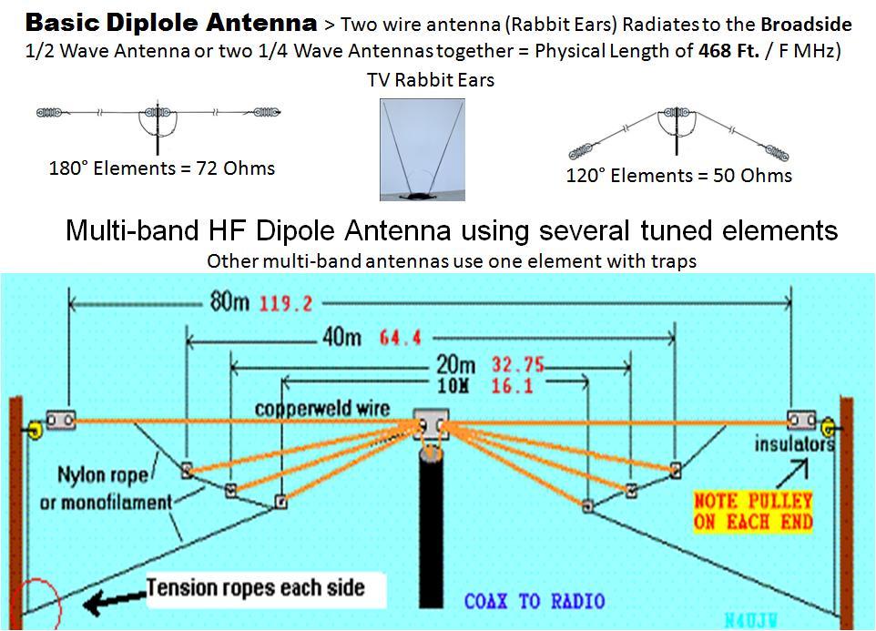
 1/2 Wave Antenna = Physical Length of 468 Ft. / F MHz) Full Wave Antenna = Physical Length of 936 Ft.")
6 RF Bands > approx equal the Speed of Light / Frequency = (300 Meters / F MHz) Polarization Physical Length (Shorter is Higher Frequency) 1/4 Wave Antenna = Physical Length of 234 Ft. / F MHz) 1/2 Wave Antenna = Physical Length of 468 Ft. / F MHz) Full Wave Antenna = Physical Length of 936 Ft. / F MHz) Vertical Antenna > Electric Field is perpendicular to the earth (Flag Pole) Horizontal Antenna > Electric Field is parallel to the earth (Cloths Line) Common Antennas 1/4 Wave > Common Mobile (whip, rubber duckie, flag pole) 5/8 Wave > Used as mobile for more Horz gain 3/4 Wave > Base for more Horz gain Least common due to size J-Pole > Mostly VHF & UHF due to size but most gain for omni Slim Jim > Like J Pole but even more gain for omni Dipole > Most common of all has small gain Dipole most common Multi-Band > Windom, OCF, G5RV Loop > Provides high Gain & Low Noise less common due to size Yagi > Most gain (Beam, Quad Beam, Array) Load Coils, Matching Coils, Traps Load Coils make an antenna look longer to the RF Matching Coils do same as load coils plus change input impedance Traps in multi-band antennas make it look shorter as freq goes up Multi-wire Dipoles (FAN) let the RF select best pair without loss 1 / 4 Wave Antenna > Commonly used antenna using ground plane for a counterpoise

7
8
9
10 Antenna Matching A tuner should be called matcher because it matches the impedance presented to the transceiver to the impedance on the feedline. You could say the tuner takes whatever you have on your feedline and makes it look like 50 Ohms resistive to the transceiver. This is a simplified answer that is not all true, but it is the general idea. Today automatic tuners are the standard; twenty years back the standard was an external manual tuner. Prior to 1980 transmitters normally had internal tuning and loading controls. Think about the controls, controls for matching, this was what you pay extra today is called a built-in tuner! Typical Automatic Antenna Tuner Block Diagram Looking at the schematic above you see many components but few are actually the key to tuning. Most are for the SWR, measuring forward and reverse power. So looking at the schematic above and the simplified version below you can start to see manufactures use switches to vary the inductance values. Other models use switches for both capacitance and inductance control. Most use series capacitors as this is generally a more efficient design. Capacitors do not contribute any significant loss in the circuit as they have very high Q. Q is the ratio of electrical resistance and reactance at resonance. Capacitor Q is much larger than the Q exhibited by most coils. Simplified Schematic Antenna Tuner In this design you will see a switch that moves the capacitor(s) from the transmitter side to the antenna side saving in hardware costs as well as practical design. It includes other features common to many commercial tuners with an antenna selector and current BALUN built-in.

11 Antenna Feedlines Feedline is required to transfer the RF output from the tuner to the antenna and is normally 50 ohm coaxial cable because the transmitters made today are designed for 50 Ohm output. Notice I said the tuner is connected to the feedline not the transmitter. The tuner s job to match the impedance from the feed input to the transmitter s 50 Ohm output has just been covered by the previous section. A 50 Ohm coaxial feedline terminated into a 50 ohm antenna at a distance of an exact half wave length are 1 to 1 transformers with very minor resistive loss. Use any other length line and you are no longer terminated in 50 Ohm impedance this also changes the impedance into something else at the transmitter end. The changed value is a function of antenna impedance, line loss, and the length and characteristic impedance of the feedline. There are three feedline characteristics to consider in your antenna system; Resistive Line Loss Antenna Impedance Length Relative to Wavelength Coaxial cable resistive loss is a one factor in an antenna system that most HAMs consider but not always. In every run, there is some loss of signal strength as the signal travels between the antenna and the tuner. The longer the run of cable, the greater the loss will be is understood. At higher frequencies, the losses in the cable are much greater. We all know not kink the cable, or fit tightly around corners can lead to splits in the jacket and shield, which will lead to a downgrade in performance over time with water intrusion. So we are now good for losses when connecting a 50 Ohm coaxial cable to a resistive 50 Ohm antenna. These are the loss numbers published by the cable manufactures. These are not the values for mismatched loads!

12 Antenna impedance must be considered to prevent reflections at the antenna from causing standing waves. The feedline must match to the characteristic impedance of the antenna to prevent reflections. It is not difficult to select a feedline to match the antenna but it is often not even considered. Coaxial cable impedance is determined its dimensions and materials used and is a purchased item. Common coax values are 50 and 75 Ohms but an alternative using parallel conductors provides values of 300, 450 and 600 Ohms determined by spacing and materials. An example of the right way is the G5RV design that matches the higher impedance dipole to the 50 Ohm coax with a tuned length of parallel feedline. Another example of the right way is matching a Windom Dipole (OCF) design high impedance to the 50 Ohm coax with a 4:1 BALUM. Looking at a typical case of a 100W transceiver connected to an 40M antenna with 100 Feet of RG-8U you can see a dramatic difference in antenna RF radiated power by matching at the antenna feed point to the feedline. The dramatic effects of matching are shown in the chart below. Relative RF Power Radiated vs. Antenna to Feedline Matching Any length of feedline can be used if you understand feedline SWR. A general rule is to use a feed length or ½ WL and measure the VSWR at the tuner-feedline connection prior to use in all bands. You can go from perfection to dead short by selecting a frequency that yields a wavelength equal to a ¼ WL multiple of the feedline length. Here is the kicker but not always, ¼ WL multiple feedline can also transform a high impedance to a low impedance. The contributions of a ¼ WL can be tricky on a multiband antenna. Sometimes HAMs blame their tuner for not working, some understand enough to add or subtract 1/8 WL from the feedline there is no magic in a ¼ WL just be aware of how it works. The feed impedance at one end is purely resistive, the impedance at the other end will also be resistive, and a random length section can be resistive at one end and yet have a complex impedance at the other end. Remember to measure your multiband antenna in all bands prior to use.
Chapter 6 Antenna Basics. Dipoles, Ground-planes, and Wires Directional Antennas Feed Lines
 Chapter 6 Antenna Basics Dipoles, Ground-planes, and Wires Directional Antennas Feed Lines Some General Rules Bigger is better. (Most of the time) Higher is better. (Most of the time) Lower SWR is better.
Technician Licensing Class T9
 Technician Licensing Class T9 Amateur Radio Course Monroe EMS Building Monroe, Utah January 11/18, 2014 January 22, 2014 Testing Session Valid dates: July 1, 2010 June 30, 2014 Amateur Radio Technician
4/25/2012. Supplement T9. 2 Exam Questions, 2 Groups. Amateur Radio Technician Class T9A: T9A: T9A: T9A:
 Amateur Radio Technician Class Element 2 Course Presentation ti ELEMENT 2 SUB-ELEMENTS Technician Licensing Class Supplement T9 Antennas, Feedlines 2 Exam Questions, 2 Groups T1 - FCC Rules, descriptions
CHAPTER 8 ANTENNAS 1
 CHAPTER 8 ANTENNAS 1 2 Antennas A good antenna works A bad antenna is a waste of time & money Antenna systems can be very inexpensive and simple They can also be very expensive 3 Antenna Considerations
4/29/2012. General Class Element 3 Course Presentation. Ant Antennas as. Subelement G9. 4 Exam Questions, 4 Groups
 General Class Element 3 Course Presentation ti ELEMENT 3 SUB ELEMENTS General Licensing Class Subelement G9 Antennas and Feedlines 4 Exam Questions, 4 Groups G1 Commission s Rules G2 Operating Procedures
General License Class Chapter 6 - Antennas. Bob KA9BHD Eric K9VIC
 General License Class Chapter 6 - Antennas Bob KA9BHD Eric K9VIC Learning Objectives Teach you enough to get all the antenna questions right during the VE Session Learn a few things from you about antennas
ANTENNAS. I will mostly be talking about transmission. Keep in mind though, whatever is said about transmission is true of reception.
 Reading 37 Ron Bertrand VK2DQ http://www.radioelectronicschool.com ANTENNAS The purpose of an antenna is to receive and/or transmit electromagnetic radiation. When the antenna is not connected directly
Antennas Demystified Antennas in Emergency Communications. Scott Honaker N7SS
 Antennas Demystified Antennas in Emergency Communications Scott Honaker N7SS Importance of Antennas Antennas are more important than the radio A $5000 TV with rabbit ears will have a lousy picture Antennas
ANTENNAS Wires, Verticals and Arrays
 ANTENNAS Wires, Verticals and Arrays Presented by Pete Rimmel N8PR 2 1 Tonight we are going to talk about antennas. Anything that will conduct electricity can be made to radiate RF can be called an antenna.
ANTENNA BASICS FOR BEGINNERS
 ANTENNA BASICS FOR BEGINNERS PART 2 -DIPOLES DIPOLES -General MULTIBAND DIPOLES RF CHOKES 1 DIPOLES Several different variations of the dipole are also used, such as the folded dipole, short dipole, cage
Beams and Directional Antennas
 Beams and Directional Antennas The Horizontal Dipole Our discussion in this chapter is about the more conventional horizontal dipole and the simplified theory behind dipole based designs. For clarity,
Emergency Antennas. Presented by Ham Hilliard W4GMM
 Emergency Antennas Presented by Ham Hilliard W4GMM Dipole antenna Vertical antenna Random wire antenna Dipole antenna The half wave dipole antenna consists of a conductive wire or rod that is half the
Technician License. Course
 Technician License Course Technician License Course Chapter 4 Lesson Plan Module - 10 Practical Antennas The Dipole Most basic antenna The Dipole Most basic antenna The Dipole Total length is ½ wavelength
Cray Valley Radio Society. Real Life Wire Antennas
 Cray Valley Radio Society Real Life Wire Antennas 1 The basic dipole The size of an antenna is determined by the wavelength of operation In free space: ~3x10 8 m/s Frequency x Wavelength = Speed of Light,
4 Antennas as an essential part of any radio station
 4 Antennas as an essential part of any radio station 4.1 Choosing an antenna Communicators quickly learn two antenna truths: Any antenna is better than no antenna. Time, effort and money invested in the
Introduction. Understanding Power Ratings. Peak Reading SWR/Wattmeter
 Introduction The MFJ-962D is a "T" network roller inductor tuner with built-in antenna switching, RF power and SWR metering and a 1:1 balun. The largest amplifiers that can safely be used include the Heathkit
Technician Licensing Class. Antennas
 Technician Licensing Class Antennas Antennas A simple dipole mounted so the conductor is parallel to the Earth's surface is a horizontally polarized antenna. T9A3 Polarization is referenced to the Earth
Antennas and Propagation Chapters T4, G7, G8 Antenna Fundamentals, More Antenna Types, Feed lines and Measurements, Propagation
 Antennas and Propagation Chapters T4, G7, G8 Antenna Fundamentals, More Antenna Types, Feed lines and Measurements, Propagation =============================================================== Antenna Fundamentals
Technician License. Course
 Technician License Course Technician License Course Chapter 4 Lesson Plan Module - 9 Antenna Fundamentals Feed Lines & SWR The Antenna System The Antenna System Antenna: Transforms current into radio waves
FCC Technician License Course
 FCC Technician License Course 2014-2018 FCC Element 2 Technician Class Question Pool Presented by: Tamiami Amateur Radio Club (TARC) WELCOME To the third of 4, 3-hour classes presented by TARC to prepare
MFJ-941E Versa Tuner II GENERAL INFORMATION:
 GENERAL INFORMATION: MFJ VERSA TUNER II The MFJ-941E is designed to match virtually any transmitter to any antenna, including dipoles, inverted-vees, verticals, mobile whips, beams, random wires, and others
1) Transmission Line Transformer a. First appeared on the scene in 1944 in a paper by George Guanella as a transmission line transformer, the 1:1
 Transmission Line Transformer a. First appeared on the scene in 1944 in a paper by George Guanella as a transmission line transformer, the 1:1") 1) Transmission Line Transformer a. First appeared on the scene in 1944 in a paper by George Guanella as a transmission line transformer, the 1:1 Guanella Balun is the basic building Balun building block.
1) Transmission Line Transformer a. First appeared on the scene in 1944 in a paper by George Guanella as a transmission line transformer, the 1:1 Guanella Balun is the basic building Balun building block.
MFJ Balanced Line Tuner
 MFJ Balanced Line Tuner Introduction The MFJ-974H balanced line antenna tuner is a fully balanced true balanced line antenna tuner, providing superb current balance throughout a very wide matching range
Milton Keynes Amateur Radio Society (MKARS)
") Milton Keynes Amateur Radio Society (MKARS) Intermediate Licence Course Feeders Antennas Matching (Worksheets 31, 32 & 33) MKARS Intermediate Licence Course - Worksheet 31 32 33 Antennas Feeders Matching
Milton Keynes Amateur Radio Society (MKARS) Intermediate Licence Course Feeders Antennas Matching (Worksheets 31, 32 & 33) MKARS Intermediate Licence Course - Worksheet 31 32 33 Antennas Feeders Matching
MFJ-969 Versa Tuner II Instruction Manual
 MFJ-969 Versa Tuner II Instruction Manual General Information The MFJ-969 is a 300 watt RF output power antenna tuner that will match any transmitter or transceiver to virtually any antenna. Peak or average
MFJ-219/219N 440 MHz UHF SWR Analyzer TABLE OF CONTENTS
 MFJ-219/219N 440 MHz UHF SWR Analyzer TABLE OF CONTENTS Introduction...2 Powering The MFJ-219/219N...3 Battery Installation...3 Operation Of The MFJ-219/219N...4 SWR and the MFJ-219/219N...4 Measuring
MFJ-949E. tuner antenowy skrzynka antenowa. Instrukcja obsługi. importer:
 Instrukcja obsługi MFJ-949E tuner antenowy skrzynka antenowa importer: PRO-FIT Centrum Radiokomunikacji InRadio ul. Puszkina 80 92-516 Łódź tel: 42 649 28 28 e-mail: biuro@inradio.pl www.inradio.pl MFJ-949E
ALWAYS ATTACH THE SAFETY ROPE TO A STABLE SUPPORT BEFORE ATTEMPTING TO ATTACH THE UNIVERSAL MOUNT TO A WINDOW FRAME OR RAIL.
 MFJ-1623 Introduction The MFJ-1623 was designed to provide portable or permanent HF communications on 30 through 10 meters and VHF on 6 meters. The universal mount design allows the user to install the
General Class License Theory III. Dick Grote K6PBF
 General Class License Theory III Dick Grote K6PBF K6pbfdick@gmail.com 1 Introduction In this session we will learn about: Feed Lines Antennas Safety As in the other theory classes, we will try to present
Lesson 11: Antennas. Copyright Winters Version 1.0. Preparation for Amateur Radio Technician Class Exam
 Lesson 11: Antennas Preparation for Amateur Radio Technician Class Exam Topics Antenna ½ wave Dipole antenna ¼ wave Vertical antenna Antenna polarization Antenna location Beam antennas Test Equipment Exam
Amateur Extra Manual Chapter 9.4 Transmission Lines
 9.4 TRANSMISSION LINES (page 9-31) WAVELENGTH IN A FEED LINE (page 9-31) VELOCITY OF PROPAGATION (page 9-32) Speed of Wave in a Transmission Line VF = Velocity Factor = Speed of Light in a Vacuum Question
Basic Wire Antennas. Part II: Loops and Verticals
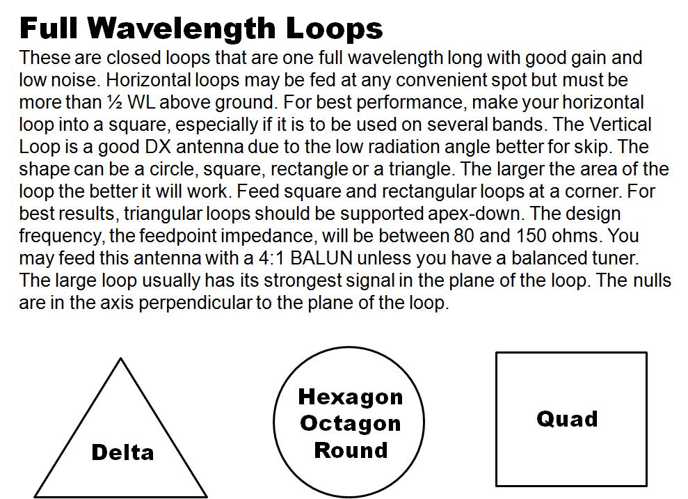
 Basic Wire Antennas Part II: Loops and Verticals A loop antenna is composed of a single loop of wire, greater than a half wavelength long. The loop does not have to be any particular shape. RF power can
1997 MFJ ENTERPRISES, INC.
 INSTRUCTION MANUAL CAUTION: Read All Instructions Before Operating Equipment MFJ ENTERPRISES, INC. 300 Industrial Park Road Starkville, MS 39759 USA Tel: 601-323-5869 Fax: 601-323-6551 VERSION 6C COPYRIGHT
Jacques Audet VE2AZX. Nov VE2AZX 1
 Jacques Audet VE2AZX VE2AZX@amsat.org Nov. 2006 VE2AZX 1 - REASONS FOR USING A BALUN - TYPES OF BALUNS - CHECK YOUR BALUN WITH AN SWR ANALYZER - MEASURING THE IMPEDANCE OF A NUMBER OF FERRITES - IMPEDANCE
Technician Licensing Class. Lesson 4. presented by the Arlington Radio Public Service Club Arlington County, Virginia
 Technician Licensing Class Lesson 4 presented by the Arlington Radio Public Service Club Arlington County, Virginia 1 Quiz Sub elements T6 & T7 2 Good Engineering Practice Sub element T8 3 A Basic Station
Optimizing Your Stations Performance
 Optimizing Your Stations Performance A few hints / techniques, recommendations for getting the most RF out to the Antenna from your HF, VHF / UHF station. Tonights Presenters: Doug Theriault NO1D John
The Fabulous Dipole. Ham Radio s Most Versatile Antenna
 The Fabulous Dipole Ham Radio s Most Versatile Antenna 1 What is a Dipole? Gets its name from its two halves One leg on each side of center Each leg is the same length It s a balanced antenna The voltages
TWO METER HOMEMADE SLIM JIM ANTENNA
 Gordon Gibby July 15, 2016 TWO METER HOMEMADE SLIM JIM ANTENNA WIRE: Start with a piece of solid #14 AWG household wire approximately 3 yards and 9 inches long (117 ) (It is easier to be a couple inches
Technician License Course Chapter 4. Lesson Plan Module 9 Antenna Fundamentals, Feed Lines & SWR
 Technician License Course Chapter 4 Lesson Plan Module 9 Antenna Fundamentals, Feed Lines & SWR The Antenna System Antenna: Transforms current into radio waves (transmit) and vice versa (receive). Feed
Development of a noval Switched Beam Antenna for Communications
 Master Thesis Presentation Development of a noval Switched Beam Antenna for Communications By Ashraf Abuelhaija Supervised by Prof. Dr.-Ing. Klaus Solbach Institute of Microwave and RF Technology Department
RX Directional Antennas. Detuning of TX Antennas.
 1. Models Impact of Resonant TX antennas on the Radiation Pattern of RX Directional Antennas. Detuning of TX Antennas. Chavdar Levkov, lz1aq@abv.bg, www.lz1aq.signacor.com 2-element small loops and 2-element
Coming next: Wireless antennas for beginners
 Coming next: Wireless antennas for beginners In other rooms: Logbook of the World (Sussex Suite) SO2R contest operation (Stable Suite) Wires for your wireless: Simple wire antennas for beginners dominic
SWR myths and mysteries.
 SWR myths and mysteries. By Andrew Barron ZL3DW September 2012 This article will explain some of the often misunderstood facts about antenna SWR at HF and uncover some popular misconceptions. The questions
Technician License Course Chapter 4
 Technician License Course Chapter 4 Propagation, Basic Antennas, Feed lines & SWR K0NK 26 Jan 18 The Antenna System Antenna: Facilitates the sending of your signal to some distant station. Feed line: Connects
Introduction LOADING COIL COUNTERPOISE ATTACHMENT ANTENNA ATTACHMENT. Figure 1: MFJ-1625 Window/Balcony Mount Antenna
 Introduction MFJ-1625 The MFJ-1625 is a 200 Watt antenna tuner that was designed to provide portable or permanent HF communications on 80 through 10 meters and VHF on 6 meters. The universal mount design
The first thing to realize is that there are two types of baluns: Current Baluns and Voltage Baluns.
 Choosing the Correct Balun By Tom, W8JI General Info on Baluns Balun is an acronym for BALanced to UNbalanced, which describes certain circuit behavior in a transmission line, source or load. Most communications
Amateur Radio License. Propagation and Antennas
 Amateur Radio License Propagation and Antennas Todays Topics Propagation Antennas Propagation Modes Ground wave Low HF and below, ground acts as waveguide Line-of-Sight (LOS) VHF and above, radio waves
A Tri Band Antenna for 2 meters, 220 MHz, and 70cm Antenna Without Radials. By: Edison Fong (WB6IQN)
") A Tri Band Antenna for 2 meters, 220 MHz, and 70cm Antenna Without Radials By: Edison Fong (WB6IQN) Twenty years ago a single band handie talkie would have been adequate for emergency use since almost
A Tri Band Antenna for 2 meters, 220 MHz, and 70cm Antenna Without Radials By: Edison Fong (WB6IQN) Twenty years ago a single band handie talkie would have been adequate for emergency use since almost
The Amazing MFJ 269 Author Jack Tiley AD7FO
 The Amazing MFJ 269 Author Jack Tiley AD7FO ARRL Certified Emcomm and license class Instructor, Volunteer Examiner, EWA Technical Coordinator and President of the Inland Empire VHF Club What Can be Measured?
The J-Pole Antenna. Gary Wescom
 The J-Pole Antenna Gary Wescom - 2018 Much has been written about the J-Pole antenna. A simple Google search will net days worth of reading material on the subject. That would tend to indicate this paper
Intermediate Course (5) Antennas and Feeders
 Antennas and Feeders") Intermediate Course (5) Antennas and Feeders 1 System Transmitter 50 Ohms Output Standing Wave Ratio Meter Antenna Matching Unit Feeder Antenna Receiver 2 Feeders Feeder types: Coaxial, Twin Conductors
Intermediate Course (5) Antennas and Feeders 1 System Transmitter 50 Ohms Output Standing Wave Ratio Meter Antenna Matching Unit Feeder Antenna Receiver 2 Feeders Feeder types: Coaxial, Twin Conductors
SOME USES FOR RF1,RF5 and VA1 ANALYSTS. SWR Measurement
 SOME USES FOR RF1,RF5 and VA1 ANALYSTS THE HANDIEST INSTRUMENTS IN DECADES! When you put up an antenna in the the old days, it could be a real struggle. The only way to tell if it was tuned to the right
COAXIAL TRANSMISSION LINE COMMON-MODE CURRENT
 COAXIAL TRANSMISSION LINE COMMON-MODE CURRENT Introduction Coaxial transmission lines are popular for their wide frequency bandwidth and high resistance to electromagnetic interference (EMI). Coax cables
Chapter 9 Antennas and Feedlines
 Chapter 9 Antennas and Feedlines Basics of Antennas Antenna Radiation Patterns. Graphical representation of spatial distribution of energy around an antenna. 3D = Full representation. 2D = Slice through
Antenna Design for FM-02
 Antenna Design for FM-02 I recently received my FM-02 FM transmitter which I purchased from WLC. I researched the forum on what antennas where being used by the DIY community and found a nice write-up
WHY YOU NEED A CURRENT BALUN
 HF OPERATORS WHY YOU NEED A CURRENT BALUN by John White VA7JW NSARC HF Operators 1 What is a Balun? A BALUN is a device typically inserted at the feed point of a dipole-like antenna wire dipoles, Yagi
Newcomers And Elmers Net: Wire Antennas Robert AK3Q
 Newcomers And Elmers Net: Wire Antennas 02-07-16 Robert AK3Q Wire antennas represent one of the greatest values in the radio hobby world. For less than the cost of a good meal out on the town you can buy
Last year I described several Low Band RX antennas that would enable you to hear DX stations on 160, 80 and 40M. This will show you how to build
 Last year I described several Low Band RX antennas that would enable you to hear DX stations on 160, 80 and 40M. This will show you how to build transmit antennas that will help you break the pileups!
Yagi beam antennas CHAPTER 10 COMPOSITION OF A BEAM ANTENNA _
 CHAPTER 10 Yagi beam antennas The Yagi beam antenna (more correctly, the Yagi Uda antenna, after both of the designers of Tohoku University in Japan 1926) is unidirectional. It can be vertically polarized
Technician License Course Chapter 4. Lesson Plan Module 10 Practical Antennas
 Technician License Course Chapter 4 Lesson Plan Module 10 Practical Antennas The Dipole Most basic antenna Total length is ½ wavelength (½ λ) Usual construction: Two equal halves of wire, rod, or tubing
MFJ-834 RF Ammeter. Introduction. Uses
 MFJ-834 RF Ammeter Introduction Congratulations on purchasing the MFJ-834 RF Ammeter. The MFJ-834 is designed for measuring in-line RF feedline current on 1.8-30 MHz while having low interaction on the
ANTENNA THEORY WAVE PROPAGATION HF ANTENNAS
 ANTENNA THEORY WAVE PROPAGATION & HF ANTENNAS FREQUENCY SPECTRUM INFORMATION Frequency range American designator below 300 Hz..ELF (extremely Low Frequency) 300-3000 Hz..ILF (Intermediate Low Frequency)
MFJ-835 RF Ammeter. Introduction. Uses
 MFJ-835 RF Ammeter Introduction Congratulations on purchasing the MFJ-835 Balanced Line RF Ammeter. The MFJ-835 is designed for measuring balanced RF feedline current on 1.8-30 MHz while having low interaction
Table of Contents. MFJ-1778 G5RV Multiband Antenna
 Table of Contents MFJ-1778 G5RV Multiband Antenna Introduction... 1 Theory Of Operation... 1 80 meter band:... 1 40 meter band:... 1 30 meter band:... 2 20 meter band:... 2 17 meter band:... 2 15 meter
MFJ-945E. tuner antenowy skrzynka antenowa. Instrukcja obsługi. importer:
 Instrukcja obsługi MFJ-945E tuner antenowy skrzynka antenowa importer: PRO-FIT Centrum Radiokomunikacji InRadio ul. Puszkina 80 92-516 Łódź tel: 42 649 28 28 e-mail: biuro@inradio.pl www.inradio.pl MFJ-945E
Chapter 5.0 Antennas Section 5.1 Theory & Principles
 Chapter 5.0 Antennas Section 5.1 Theory & Principles G3C11 (B) p.135 Which of the following antenna types will be most effective for skip communications on 40-meters during the day? A. A vertical antenna
Adjust Antenna Tuners Antenna Measurements Capacitor Measurement Measure Feed Point Impedance Measure Ground Loss Inductor Measurement
 The Micro908 antenna analyzer is an extremely useful instrument to have around the ham shack or homebrewer s workbench. This section describes the basic uses, as well as some advanced techniques for which
MFJ-208 VHF SWR Analyzer
 MFJ-208 VHF SWR Analyzer Thank you for purchasing the MFJ-208 VHF SWR Analyzer. The MFJ-208 gives you a direct readout of your antenna's SWR without the need for formulas or indirect readings. The MFJ-
Range Considerations for RF Networks
 TI Technology Days 2010 Range Considerations for RF Networks Richard Wallace Abstract The antenna can be one of the most daunting components of wireless designs. Most information available relates to large
L. B. Cebik, W4RNL. Basic Transmission Line Properties
 L. B. Cebik, W4RNL In the course of developing this collection of notes, I have had occasion to use and to refer to both series and parallel coaxial cable assemblies. Perhaps a few notes specifically devoted
Bob Brehm, AK6R Chief Engineer Palomar-Engineers.com
 Bob Brehm, AK6R Chief Engineer Palomar-Engineers.com HAMCON 2017 - September 2017 This presentation available on website Copyright 2013-2017 Palomar Engineers, Inc. End Fed Workshop Topics Popular End
G7FEK LIMITED SPACE ANTENNA
 80, 40, 30, 17, 15, 12 m see tet for 20 & 10m operation For 20m operation add red wire 16.5ft ( 5.1m) 24 ft (7.4m) Copyright 2009 G7FEK During the 1980s Mike, G7FEK, described a limited space antenna suitable
Antenna? What s That? Chet Thayer WA3I
 Antenna? What s That? Chet Thayer WA3I Space: The Final Frontier Empty Space (-Time) Four dimensional region that holds everything Is Permeable : It requires energy to set up a magnetic field within it.
Portable Vertical Antenna for 75m & 40m
 Portable Vertical Antenna for 75m & 40m BOXBORO August 2012 Jacques VE2AZX Web: ve2azx.net 1 Objectives 1- Portable Antenna for 75m et 40m 2- Low radiation angle for DX 3- Efficient 4- Easy to install.
Half-Wave Dipole. Radiation Resistance. Antenna Efficiency
 Antennas Simple Antennas Isotropic radiator is the simplest antenna mathematically Radiates all the power supplied to it, equally in all directions Theoretical only, can t be built Useful as a reference:
Bob Brehm, AK6R Chief Engineer Palomar-Engineers.com
 Bob Brehm, AK6R Chief Engineer Palomar-Engineers.com LAKESIDE - October 2017 This presentation available on website Copyright 2013-2017 Palomar Engineers, Inc. End Fed Workshop Topics Popular End Fed Antenna
Antennas 101 Don t Be a 0.97 db Weakling! Ward Silver NØAX
 Antennas 101 Don t Be a 0.97 db Weakling! Ward Silver NØAX Overview Antennas 101 2 Overview Basic Antennas: Ground Plane / Dipole How Gain and Nulls are Formed How Phased Arrays Work How Yagis Work (simplified)
Users Manual. 200W HF/50MHz Band Auto Antenna Tuner. Model HC-200AT
 Users Manual 200W HF/50MHz Band Auto Antenna Tuner Model HC-200AT Caution 1. Never remove or open the tuner cover while transmitting. When there is RF in the circuits of the tuner, there will be high voltage
I recently came across a No-Counterpoise antenna described by designed by Peter Millis M3KXZ and based on an original design by K9ESE.
 M3KXZ 'no counterpoise' antenna I recently came across a No-Counterpoise antenna described by designed by Peter Millis M3KXZ and based on an original design by K9ESE. Details of the antenna can be found
WCARES NEEDS YOU! CONSIDER MAKING A TECHNICAL PRESENTATION AT AN UPCOMING CHEW & CHAT MEETING LEARN SOMETHING NEW AND PRESENT
 WCARES NEEDS YOU! CONSIDER MAKING A TECHNICAL PRESENTATION AT AN UPCOMING CHEW & CHAT MEETING SHARE WHAT YOU KNOW LEARN SOMETHING NEW AND PRESENT IT CONTACT TIM AD4CJ AD4CJ@arrl.net 1 Transmission Line
JEREMY HALEY, WG9T LONGMONT AMATEUR RADIO CLUB. Longmont Amateur Radio Club
 RF IMPEDANCE AND THE SMITH CHART JEREMY HALEY, WG9T LONGMONT AMATEUR RADIO CLUB 1 RESISTANCE, REACTANCE, AND IMPEDANCE RESISTANCE Energy conversion to heat. REACTANCE Capacitance: Energy storage in electric
2006 MFJ ENTERPRISES, INC.
 2500 Watt SSB / CW Tuner Model MFJ-9982 INSTRUCTION MANUAL Requires 9V Battery or 12V DC Source for Meter Operation CAUTION: Read All Instructions Before Operating Equipment MFJ ENTERPRISES, INC. 300 Industrial
Tuning a 160M full sized vertical with strong AM broadcast RF present on the antenna. Jay Terleski, WX0B
 Tuning a 160M full sized vertical with strong AM broadcast RF present on the antenna. Jay Terleski, WX0B I often get asked about how to match a ¼ WL vertical to a 50 ohm transmission line and what to do
Antenna Fundamentals
 HTEL 104 Antenna Fundamentals The antenna is the essential link between free space and the transmitter or receiver. As such, it plays an essential part in determining the characteristics of the complete
THE ELECTRIC WAVE BALUNS AND COAXIAL AERIALS
 THE ELECTRIC WAVE BALUNS AND COAXIAL AERIALS If you are dealing with radiofrequency aerials you might like to experiment with the configurations proposed. In fig. 1 there is a balun which transforms an
Ground-Mounted Verticals. Dispelling the Myths and Misconceptions
 Dispelling the Myths and Misconceptions Let s start with a quiz on vertical antennas and radials. Answers will be there to discover, as we proceed through the presentation. To be most effective, a ground-mounted
Miniature Magnetic Loops By David Posthuma, WD8PUO
 Miniature Magnetic Loops By David Posthuma, WD8PUO Application Notes and Articles A General Overview After several years of curiosity and several months of research, I recently built two magnetic loops.
CHAPTER - 6 PIN DIODE CONTROL CIRCUITS FOR WIRELESS COMMUNICATIONS SYSTEMS
 CHAPTER - 6 PIN DIODE CONTROL CIRCUITS FOR WIRELESS COMMUNICATIONS SYSTEMS 2 NOTES 3 INTRODUCTION PIN DIODE CONTROL CIRCUITS FOR WIRELESS COMMUNICATIONS SYSTEMS Chapter 6 discusses PIN Control Circuits
How to use your antenna tuner.
 How to use your antenna tuner. There's more to it than what is in your manual or on most how to do it websites! http://www.arrl.org/tis/info/ant-tuner-op.html Here is a neat site with a "T" network simulator.
Installation Instructions Hustler 6-BTV Trap Vertical
 Installation Instructions Hustler 6-BTV Trap Vertical ASSEMBLY 1. Check the package contents against the parts list on page 2. 2. WARNING. Installation of this product near power lines is dangerous. For
ARNSW Balun Day. Balun construction
 ARNSW Balun Day Balun construction Typical Baluns All built from locally available components. Balun uses Most baluns are used to match the 50Ω output of a transceiver to an antenna. A centre fed dipole
Installation Instructions Hustler 6-BTV Trap Vertical
 Installation Instructions Hustler 6-BTV Trap Vertical ASSEMBLY 1. Check the package contents against the parts list on page 2. 2. WARNING. Installation of this product near power lines is dangerous. For
MFJ-249B HF/VHF SWR ANALYZER
 TABLE OF CONTENTS MFJ-249B... 2 Introduction... 2 Powering The MFJ-249B... 3 Battery Installation... 3 Alkaline Batteries... 3 NiCd Batteries... 4 Power Saving Mode... 4 Operation Of The MFJ-249B...5 SWR
MFJ ENTERPRISES, INC.
 Model MFJ-962D Requires 9VDC Battery or 12VDC Source for Meter Operation INSTRUCTION MANUAL CAUTION: Read All Instructions Before Operating Equipment MFJ ENTERPRISES, INC. 300 Industrial Park Road Starkville,
Page 1The VersaTee Vertical 60m, 80m Modular Antenna System Tutorial Manual
 Page 1The VersaTee Vertical 60m, 80m Modular Antenna System Tutorial Manual by: Lou Rummel, KE4UYP Page 1 In the world of low band antennas this antenna design is unique in many different ways. 1. It is
A Transmatch for Balanced or Unbalanced Lines
 A Transmatch for Balanced or Unbalanced Lines Most modern transmitters are designed to operate into loads of approximately 50 Ω. Solid-state transmitters produce progressively lower output power as the
What causes the Out-of-Balance Current in the coax and why does it Radiate?
 The EH Antenna - Out of Balance Current or Longitudinal Mode Current in the Coaxial Cable causes radiation from the coax. But how large a proportion of the total power is radiated or lost from this Current?
July 1995 QST Volume 79, Number 7
 Lab Notes Prepared by the ARRL Laboratory Staff (e-mail: tis@arrl.org) By Mike Tracy, KC1SX Technical Information Service Coordinator Q: I m just getting started on VHF and UHF FM and I want to set up
Definitions of Technical Terms
 Definitions of Technical Terms Terms Ammeter Amperes, Amps Band Capacitor Carrier Squelch Diode Dipole Definitions How is an ammeter usually connected = In series with the circuit What instrument is used
What is a BALUN or UNUN:
 What is a BALUN or UNUN: A device to connect different types of antennas to various feed lines. Can transform impedances, choke common mode or change balanced to unbalanced BALUN Balanced to Unbalanced