ANTENNAS Wires, Verticals and Arrays
|
|
|
- Simon Gallagher
- 6 years ago
- Views:
Transcription
1 ANTENNAS Wires, Verticals and Arrays Presented by Pete Rimmel N8PR 2
2 1
3 Tonight we are going to talk about antennas. Anything that will conduct electricity can be made to radiate RF can be called an antenna. People are experimenting with columns of salt water as antennas. Kurt N. Sterba, in his articles in Worldradio Magazine, used to write about making bedspring antennas. I worked another ham on 40 Meter CW with a 6 ft. piece of wire leading to a 100 watt light bulb! But what is important is how to build an EFFECTIVE ANTENNA that hopefully will put your signal to some place on the globe where you want it to go. 3
4 The starting point is to decide where you want your signal to go, and then see if you can put up an antenna at your QTH that will accomplish that goal. What affects where your signal goes? 1. Height above ground affects take off angle -- low for close in work, high for DX (H-pol) 2. Polarization of the antenna verticals are omni-directional, horizontal antennas usually are not. (always vertical for repeaters) 3. Gain or directivity of the antenna puts more power in the desired direction 4
5 Antenna types: Wire antennas -- Dipoles -- G5RV -- Zepp -- Off center fed Horizontal arrays +Yagi +Quad +Wires +Commercial Verticals -¼ wave -Arrays -Commercial 5
6 DIPOLES Almost all antennas are based on a variation of a Half Wave Dipole. Most antennas are compared to the radiation characteristics of a half wave dipole. A half wave dipole ½ λ Dipole has a radiation pattern like a figure 8. This is simple physics 6
7 In this figure the dipole is in the vertical axis and we are looking down on the wire from above. Radiation is maximal in the plane of the wire, and minimal off the ends of the antenna 7
8 Calculating the length of a Half Wave Dipole (bare wire) (for insulated wire deduct 2-3% for Vf [velocity factor]) For a λ/2 Dipole: Length (ft.) = 468 f(mhz) 8
 = Length (ft) What if we use this formula, cut")
9 EXTRA! How to tune the length of an antenna using an MFJ Antenna analyzer Let s build a 10 Meter Dipole We know the formula for a ½ wave dipole: 468/f (MHz) = Length (ft) What if we use this formula, cut it to length and find that the antenna is not resonant on the frequency that we specified? How do we decide how much to cut off, assuming we were smart enough to make the antenna a bit long? 9


10 Let s say that we decided to cut the 10 meter dipole for SSB and used MHz for our center frequency. 468/28.4 = feet We cut the antenna and run 75 ohm coax to it. By using the MFJ analyzer, we find that the minimum SWR dip in the antenna is at 28.0 MHz. We call this the resonant frequency. 10
11 We can plot the readings from the MFJ meter: SWR Curve As Measured + --> Desired SWR Curve 11
12 Remember, we cut the antenna to Ft Because the resonant frequency is lower than the design frequency, the antenna is TOO LONG! How much should we cut off? Let s use the formula at the frequency where we found the best SWR dip: (resonance) 468/28.0 = feet Take = 0.24 ft x12 = 2.88 Inches We must shorten the antenna 2-7/8 to make it resonant at 28.4 MHz! NOTE: You can use the SWR meter on your rig to take the same measurements! 12
13 WHAT COULD HAVE AFFECTED THE RESONANT FREUQENCY? 1. Was it bare or insulated wire? 2. What was the diameter of the wire? Tubing? (VHF) (Thicker Dia.= Shorter element) 3. How long was the coax lead to the antenna between the braid and where the coax and braid was attached to the elements? 4. How high was the antenna above ground? 5. Were there nearby objects that could have coupled with the antenna? 6. How did we attach the ends and center to insulators? 13
14 Length In feet
15 VOLTAGE ON THE WIRE On a center fed Half Wave Dipole the voltage at the feed point is at a minimum. at the ends of the wire is at highest voltage. CURRENT ON THE WIRE On the same wire, the current is at a maximum at the feed point and a minimum at the ends. We always want the high current point as high as possible above ground 15
16 Here is why it is best not to feed full wave antennas at the middle, or half wave verticals at the bottom. We cannot feed an antenna (generally) at a high voltage point. We must feed it at a voltage null which is also a high current point A or B in the top part of the drawing. 16
17 O -- You can feed a full wave wire at the low voltage points with ladder line and use an antenna tuner to match it to the output of your transmitter. 17
18 VERTICALS: 18

19 Extra! Your Rubber Duckie can be Half of the Dipole just clip on a ¼ wave long wire to the ground side of the BNC and you have a more effective antenna! For 2 meters this wire is about 19 ½ inches long. That will work for 440 as well or clip on a 6 wire as on the right. 19
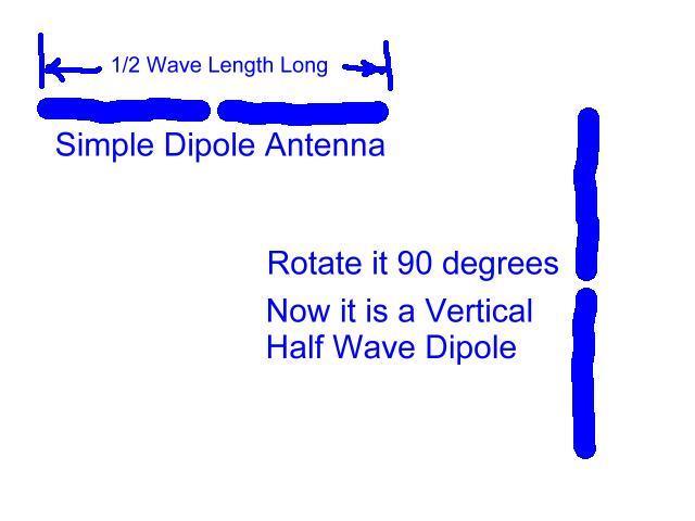
20 Let s take that dipole and turn one of the horizontal wires 90 degrees and make it into a vertical element. 20
21 We still have a half wave antenna, but one element is in the vertical plane, and the other one is in the horizontal plane. This is a basic λ/4 vertical. Currents and voltages are the same as they are in a half wave dipole. Now we can replace the horizontal element with A counterpoise, radial system or ground. 21
22 Add three more λ/4 radials and you have made a ground plane antenna. It can be a few feet above the ground or elevated high above ground. The feed point impedance of this antenna is approximately 37 Ohms. By tipping the four radials down about 45 degrees you can get a good 50 Ohm match to coax cable 22
23 Here the λ/4 radials of the antenna have been replaced by a ground. The ground reflection creates an image that becomes the other part of the half wave antenna. The antenna can be fed against a counterpoise laid on the ground. This can be a few wires of random length. Ideally, 120 λ/4 to λ/2 radials will create an efficient counterpoise 23
24 24
25 HALF WAVE END FED VERTICAL (AND HORIZONTAL) ANTENNAS Many of you have built or seen end fed wire antennas that are ½ wavelength long. These are a special case where a choke /transformer takes the 50 Ohm Coax impedance and transforms it into a high impedance that will feed an end fed half wave antenna. These antennas usually are only used on the band for which they are designed since the matching circuit will not work well on another band AND usually fed with LOW power. These antennas can be used as a horizontal, sloping or vertical antenna. Patterns will be similar to a dipole or vertical. Sloping patterns depend on the angle. As you approach 45 degrees from vertical, they start to radiate more broadside 90 degrees each side of the angle where they slope away from vertical. 25

26 This is a ½ wave 20 Meter vertical end fed wire Notice the symmetrical pattern D azimuth plot of antenna Looking down from the top Side view of antenna 3D elevation plot 26


27 This is the ½ wave 20 meter sloping wire with the wire 45 degrees from vertical. Note the null off the end and the pattern better broadside than in line with the antenna NOTE much of the signal Is going almost straight up NOTE: Pattern is becoming more broadside than symmetrical 27
28 Loop antennas Loop antennas share one common factor. The ends of a dipole antenna are connected together to form a closed antenna. This antenna has more gain broadside to it than a dipole, if in the vertical plane. It is usually 1λ +5% long on the desired band. Loop antennas are usually quieter than long wire Antennas when receiving. ie. They are less susceptible to man made noise and static. 28
29 The large vertical loop antenna is similar to a dipole, except that the ends of the dipole are connected to form a circle, triangle or square. Typically such a loop is some multiple of a half or full wavelength in circumference. Good results can be had with a 1λ loop. A loop has a pattern similar to a dipole with the maximum radiation broadside to the plane of the loop. The minimum is in the plane of the loop. 05/02/2016 A single N8PR full wave loop has about 3 db gain over a dipole 29
30 The Folded Dipole is a special case of a closed loop antenna. It is 1/2λ long and only a few inches high. 1/4 Wave length of 75 OHM coax as a transformer will match a 50 OHM coax cable 30
31 A round or square loop that is fed at the top or center of the bottom leg will be horizontally polarized. A round or square loop that is fed in the middle of the side will be vertically polarized. HORIZONTALLY POLARIZED QUAD LOOP 31
32 A delta loop that is fed 1/4 wave down from the top will be vertically polarized. If it is fed at the top or the middle of the bottom, or bottom corner, it will be horizontally polarized Why would you want horizontal or vertical polarization? 32
33 As you design your antenna, you must decide where you want your signal to go. Short skip, cloud warmer antennas are good for working close in stateside and the Caribbean use horizontal polarization. If you can get the antenna 1-2 wavelengths above ground, a horizontal antenna may be good for DX OR FOR DX to Europe, Asia, South America or half way around the world use a vertical antenna for lower take-off angle and longer skips. 33
34 A horizontal loop held up equally high at 4 corners and fed with ladder line or a balun will perform well on a number of bands. Its height above ground will determine its vertical takeoff pattern. Usually, on the low bands, it is used as a cloud warmer to talk to near in stations. It is also omni-directional (almost) It can be 1λ or longer on desired bands. It must be at least 1λ long on the lowest band used. (80M antenna in figure above) 34
35 Before we talk about parasitic antennas and arrays, lets talk about various wire antennas that we can build and some general characteristics of some antennas: Dipoles-- flat, sloping, inverted Vee G5RV a special multiband dipole Zepp end fed wire Windom off center fed wire Loops Square, Delta, Rectangle 35
36 Dipole antennas work best when horizontal. They also work well when operated on odd multiples of a half wavelength. (40M -> 15 M; 80M -> 30M) 36

37 The take off angle of a dipole or any horizontal antenna is dependent on its height above ground. To the right are patterns of a half wave dipole from 1/8 wave above ground to 2 wavelengths above ground. This holds for all HF Frequencies. These patterns occur and vary due to the ground reinforcement and reflection of the RF. 1/8 ¼ 3/8 ½ 5/8 ¾ 7/8 1 wave high 1-1/2 2 waves high 37
38 (FAN DIPOLE) You can feed more than one dipole with the same feed line, but you must keep the wires somewhat separated to be effective, otherwise they interact and detune each other and nothing works. 38
39 Sloping Dipoles must be resonant, and can be held up by supporting one end higher than the other. The feed line should be led away at right angles to the wires. It will show a small gain in the direction that the wire slopes. METAL Gain 39
40 Inverted Vee antennas are easy to erect because they can be held up by only one support. It is imperative that the included angle between the two wires is greater than 90 degrees, otherwise canceling will occur and the o antenna will not radiate. ~120 angle = 50 Ohm feed impedance. The inverted vee has horizontal polarization broadside to the antenna and vertical components off the ends. 40
41 The G5RV antenna is a special dipole that by design (or accident of properties) allows a dipole that is fed with a special length of ladder line, a balun and coax cable to radiate fairly well on the HF bands. This antenna is usually 102 feet long. The ladder line to it is 34 feet long. The two lengths added together in one instance create two ~λ/4 wires on 80 Meters, and other resonant lengths for the higher bands from 40 through 10 meters. It must be fed with a Balun, to match a coax feed line. 41
42 G5RV Multiband Antenna And the New Davie Windom Antenna by Sandy KK4OXM (Like the antenna hanging from the crane last Field Day) 42
43 Voltage on the G5RV on Various Bands A variant of this antenna can be fed with ladder line all the way to a tuner in the ham shack. It is best that this antenna be as horizontal as possible, but sloping the ends down a bit will not affect the antenna radiation patterns too much. 43
44 The Zepp antenna derives from the end fed wires that trailed the zeppelin airship. It was end fed, and unless it is an odd multiple of half wavelengths on the band desired, it will be difficult to feed. The longer this antenna is in wavelengths, the more the pattern is skewed away from broadside radiation toward a more end fire pattern. 44
45 PATTERN A Windom antenna is a wire antenna that should be cut to resonance. It is off center fed, which allows multi-band operation if fed with ladder line. Ideally, the feed point is placed at a λ/4 away from one end on the favorite band to be used. Hopefully, the other bands will still find an acceptable match relative to that feed point. It can be fed with ladder line or a single wire feed. 45
46 Question: How do you use an antenna tuner to tune an antenna???? 46
47 Question: How do you use an antenna tuner to tune an antenna? Answer: You don t tune the antenna with a tuner. You create a match between the transmitter and the transmission line with a tuner. This allows the transmitter to put out it s maximum power. If there is a poor match, the protection circuits for the solid state finals will cut back on the output power of your rig. NOTE: A pi-network final in a tube rig is a built in tuner. Only by altering the antenna do you tune it or make it resonant. 47
48 Using an antenna tuner in line with an antenna creates a resonant system, where the transmitter sees a perfect Ohm load for which it was designed. This might not be a resonant antenna because the tuner can match any random length or it could be a proper ½ wave antenna with the feed line to the tuner. A Resonant Antenna is an antenna or antenna plus matching system (L-C network) which presents a Ohm load to a piece of coax which then is led to the output of the transmitter. The L-C network could be a gamma match (yagi), phasing line (vertical), torroid/capacitor network (1/2 wave end feed) or other similar network that matches the impedance of the antenna to 50 Ohm coaxial cable that can then be led inside directly to the transmitter. 48
49 A resonant antenna could be: A dipole or inverted vee cut to ½ wavelength fed with coax A ¼ wave ground plane fed with coaxial cable. A G5RV antenna with the proper balun feeding the coax A 5/8 wave vertical with a proper tuned circuit to the coax A Yagi antenna or Quad antenna with proper matching to coax A set of phased verticals or Yagis with proper matching network An end fed wire ½ wave with the proper match to coaxial cable And many more Unless they have traps (tribander, multiband vertical, trap or fan dipole) they usually are only resonant on one band. (SteppIR antennas change lengths to be resonant) Basically any antenna which shows a 1:1 SWR at the coax when plugged into the transmitter, not needing a tuner to match it. 49
50 Harmonically fed dipole antenna patterns We know the typical pattern of a half wave dipole a figure 8 Here is the radiation pattern when that same wire is fed as a full wave antenna the pattern is now like a 4 leaf clover 50
51 At Left is a 3/2λ Antenna 3/2 wave 2 wave 3 wave 4 wave 8 wave These are higher multiple patterns. You can see how the patterns skew toward the ends as the wire gets longer. 51
52 DIRECTIONAL ARRAYS Take the antennas we have just discussed and we can create arrays of them to force the RF to be focused in one or two directions. This creates gain in those antennas relative to a dipole, loop or vertical antenna. These antennas are Yagis, Quads and phased vertical arrays. The more elements, the more gain in a given direction. This can be good and bad. Good: We have more ERP in a given direction. Bad: We can t hear or be heard as well in other directions. 52


53 The Yagi Uda Antenna The Yagi antenna consists of two or more elements. The driven element is a dipole and the directors and reflector are called parasitic elements. They are resonant elements and will cause the RF to be reflected or directed in a specific direction giving the antenna gain in that direction. 53
54 The yagi antenna ADDITIONAL DIRECTOR(s)
55 A 4 element Yagi polar plot shows that the Half Power Beamwidth (3 db down points) is about 50 degrees. The antenna has about 8 db gain over a dipole (dotted line) and a front-to-back ratio of about 18 db. Since the pattern is broad, precise aiming is not necessary. 55

56 A 3 element Yagi, at various heights is compared to a dipole at similar heights. The same amount of radiated energy is seen by the area of both curves being equal. Only the Yagi concentrates the energy more in one direction. 56
57 As the number of elements increase, so does the forward gain of the Yagi. Once it is 1 λ above ground, the ground effects are lessened and the antenna gain is as if it were in free space. 05/02/2016 Subtract N8PR 2.3 db for reference to a dipole antenna. 57

58 The Hy Gain TH-11 covers 20, 17, 15, 12, and 10 Meters With good results. It weighs 88 pounds. Forward gain is in The area of 7.5 to 9.2 dbi depending on the band. $
 on each band. It has two active elements on each band.")
59 The Force 12 XR-5 antenna covers 5 bands 10/20M It weighs 56 # and has gain figures approximately 4.5 dbd (6.7 dbi) on each band. It has two active elements on each band. $

60 Mosely makes a nice 3 element tribander with an add on WARC Dipole for 12 & 17 Gain is typically 7-8 db on and unity on Wt 35 Lbs/54 $612/$916 for classic Jr./Classic (KW+) 60

61 The Cushcraft MA5B 5 band trap yagi shows gain in the 3.5 to 5 dbd range for 10, 15, and 20M and unity with the resonant dipoles on 12 and 17 M. It weighs 26 # and will handle 1200 W PEP. $
62 There are many tribanders that are 2 to 6 element trapped antennas. They cover the Meter bands but usually not the WARC bands 12 & 17 M. The reason that there are so many is that they have been around much longer, since they were designed before the WARC bands were created. Also, they are in demand by contesters where only the non-warc bands are used. To compliment them, there are duo-band trap yagis available for 12 & 17 meters that can be added to a stack. Also, Single band yagi antennas are available for those who prefer only one band, or want to stack them in a Christmas tree array, or on several different towers. Cushcraft also makes a D3W Dipole for 12/17/30 Meters. It can be mounted above a tribander and rotated with the 05/02/2016 other N8PR yagis 62
63 The SteppIR series of antennas are the new generation of technology. Each element in the Yagi or vertical antenna slides inside a hollow fiberglass housing. Each element length is continuously adjustable using a stepper motor (thus the name) to make each element the proper length for the operating frequency chosen. The adjustments can be made manually or automatically. You can have your rig 05/02/2016 or logging N8PR program tell the antenna the frequency. 63

64 Quad antennas Quad antennas are similar to the Yagi antenna in that they use a driven element and a reflector and/or directors to focus the RF in a desired direction. The only difference is that the elements are loops and not dipoles or linear elements 64

65 Being a loop antenna, the quad is a quieter receive antenna. It has a gain figure per element a bit higher than a Yagi. Remember a full wave loop has a gain figure of 3 db over a dipole to start with. 65

66 The quad is easily placed on multiple bands by interlacing resonant elements on each set of spreaders. The driven elements can be driven in parallel or individually. Sometimes smaller spreaders are used to mount intermediate elements for the higher frequencies. This creates a better spacing between those elements and adds gain. 66
67 Vertical Arrays Just like Yagi or Quad arrays of elements, the vertical antenna is suited to creating gain in a given direction. By arranging the elements in a specific orientation and phasing how the RF is delivered to the antennas, all elements are usually active and radiating. When the signals from the various elements meet, they reinforce or cancel similar to waves in a pond when several stones are thrown into it simultaneously or in succession. The radiation patterns are determined by element spacing and phase lag or lead of the RF 67
68 Except for the ground plane verticals discussed earlier, vertical antennas are usually best suited for the low bands, 160, 80 and sometimes 40 Meters. They can be λ/4 tall or trap/coil loaded to shorten them. If you have a large area, the verticals can be put up in various configurations to give gain, just like Yagi antennas. 2, 3, 4 or more verticals can be fed in or partially out of phase to produce gain in a desired direction. This is a topic that could consume several nights. 68

69 Spacing: 1/8 wave 1/4 3/8 1/2 0 The plots shown here are for a pair of phased verticals fed with equal current each, with spacing and phase lag between the two verticals as shown. Phasing can be done by using different lengths of coax to each vertical

70 4 - ¼ wave verticals phased: D C C D A B A B All 4 verticals are fed diagonally with two in phase and the leading and lagging corners fed 90 degrees leading or lagging to produce gain as shown above. A=+90deg.; B&D= 0deg.; C= -90 degrees phase. 70
71 Commercial, trapped verticals can be made to perform well on many of the HF bands. They must be fed against a counterpoise or ground system. (Right) Butternut HF9V 80-6M Vertical. $

72 Exceptions to the need for radials or a counterpoise are the R5, R6, R8 and MFJ verticals. The R series are end fed half wave antennas with a high impedance matching system for a feed. (Right) Cushcraft R8 40-6M Vertical $
73 The MFJ is an off-center fed vertical dipole with the trapped lower resonant parts of the antenna rotated 90 degrees. (Right) MFJ M Vertical $

74 This extendable vertical can be used at home or on an RV or at field day. It contains a flexible wire and extends to 32 feet. When nested it is 4 feet long. Here an antenna tuner feeds the vertical against the chassis of the RV and other wires as a counterpoise. Under $ Sold as Eagle 1 Also see Jackkite 32 ft. poles 74
75 75
Chapter 6 Antenna Basics. Dipoles, Ground-planes, and Wires Directional Antennas Feed Lines
 Chapter 6 Antenna Basics Dipoles, Ground-planes, and Wires Directional Antennas Feed Lines Some General Rules Bigger is better. (Most of the time) Higher is better. (Most of the time) Lower SWR is better.
The New and Improved Carolina Windom Antenna and ½ Wave End Fed 20 Meter Vertical and Sloping Wire Antennas. EZNEC analysis by Pete Rimmel, N8PR
 The New and Improved Carolina Windom Antenna and ½ Wave End Fed 20 Meter Vertical and Sloping Wire Antennas EZNEC analysis by Pete Rimmel, N8PR Keeps RF off the Coax below this point / (part of)/ That
Antennas Demystified Antennas in Emergency Communications. Scott Honaker N7SS
 Antennas Demystified Antennas in Emergency Communications Scott Honaker N7SS Importance of Antennas Antennas are more important than the radio A $5000 TV with rabbit ears will have a lousy picture Antennas
CHAPTER 8 ANTENNAS 1
 CHAPTER 8 ANTENNAS 1 2 Antennas A good antenna works A bad antenna is a waste of time & money Antenna systems can be very inexpensive and simple They can also be very expensive 3 Antenna Considerations
4/29/2012. General Class Element 3 Course Presentation. Ant Antennas as. Subelement G9. 4 Exam Questions, 4 Groups
 General Class Element 3 Course Presentation ti ELEMENT 3 SUB ELEMENTS General Licensing Class Subelement G9 Antennas and Feedlines 4 Exam Questions, 4 Groups G1 Commission s Rules G2 Operating Procedures
Antennas 101 Don t Be a 0.97 db Weakling! Ward Silver NØAX
 Antennas 101 Don t Be a 0.97 db Weakling! Ward Silver NØAX Overview Antennas 101 2 Overview Basic Antennas: Ground Plane / Dipole How Gain and Nulls are Formed How Phased Arrays Work How Yagis Work (simplified)
Least understood topics by most HAMs RF Safety Ground Antennas Matching & Feed Lines
 Least understood topics by most HAMs RF Safety Ground Antennas Matching & Feed Lines Remember this question from the General License Exam? G0A03 (D) How can you determine that your station complies with
General License Class Chapter 6 - Antennas. Bob KA9BHD Eric K9VIC
 General License Class Chapter 6 - Antennas Bob KA9BHD Eric K9VIC Learning Objectives Teach you enough to get all the antenna questions right during the VE Session Learn a few things from you about antennas
Basic Wire Antennas. Part II: Loops and Verticals
 Basic Wire Antennas Part II: Loops and Verticals A loop antenna is composed of a single loop of wire, greater than a half wavelength long. The loop does not have to be any particular shape. RF power can
Coming next: Wireless antennas for beginners
 Coming next: Wireless antennas for beginners In other rooms: Logbook of the World (Sussex Suite) SO2R contest operation (Stable Suite) Wires for your wireless: Simple wire antennas for beginners dominic
Newcomers And Elmers Net: Wire Antennas Robert AK3Q
 Newcomers And Elmers Net: Wire Antennas 02-07-16 Robert AK3Q Wire antennas represent one of the greatest values in the radio hobby world. For less than the cost of a good meal out on the town you can buy
4 Antennas as an essential part of any radio station
 4 Antennas as an essential part of any radio station 4.1 Choosing an antenna Communicators quickly learn two antenna truths: Any antenna is better than no antenna. Time, effort and money invested in the
Beams and Directional Antennas
 Beams and Directional Antennas The Horizontal Dipole Our discussion in this chapter is about the more conventional horizontal dipole and the simplified theory behind dipole based designs. For clarity,
Cray Valley Radio Society. Real Life Wire Antennas
 Cray Valley Radio Society Real Life Wire Antennas 1 The basic dipole The size of an antenna is determined by the wavelength of operation In free space: ~3x10 8 m/s Frequency x Wavelength = Speed of Light,
Last year I described several Low Band RX antennas that would enable you to hear DX stations on 160, 80 and 40M. This will show you how to build
 Last year I described several Low Band RX antennas that would enable you to hear DX stations on 160, 80 and 40M. This will show you how to build transmit antennas that will help you break the pileups!
Antennas and Propagation Chapters T4, G7, G8 Antenna Fundamentals, More Antenna Types, Feed lines and Measurements, Propagation
 Antennas and Propagation Chapters T4, G7, G8 Antenna Fundamentals, More Antenna Types, Feed lines and Measurements, Propagation =============================================================== Antenna Fundamentals
General Class License Theory III. Dick Grote K6PBF
 General Class License Theory III Dick Grote K6PBF K6pbfdick@gmail.com 1 Introduction In this session we will learn about: Feed Lines Antennas Safety As in the other theory classes, we will try to present
Chapter 9 Antennas and Feedlines
 Chapter 9 Antennas and Feedlines Basics of Antennas Antenna Radiation Patterns. Graphical representation of spatial distribution of energy around an antenna. 3D = Full representation. 2D = Slice through
Half-Wave Dipole. Radiation Resistance. Antenna Efficiency
 Antennas Simple Antennas Isotropic radiator is the simplest antenna mathematically Radiates all the power supplied to it, equally in all directions Theoretical only, can t be built Useful as a reference:
Other Arrays CHAPTER 12
 CHAPTER 12 Other Arrays Chapter 11 on phased arrays only covered arrays made of vertical (omnidirectional) radiators. You can, of course, design phased arrays using elements that, by themselves, already
The first thing to realize is that there are two types of baluns: Current Baluns and Voltage Baluns.
 Choosing the Correct Balun By Tom, W8JI General Info on Baluns Balun is an acronym for BALanced to UNbalanced, which describes certain circuit behavior in a transmission line, source or load. Most communications
Emergency Antennas. Presented by Ham Hilliard W4GMM
 Emergency Antennas Presented by Ham Hilliard W4GMM Dipole antenna Vertical antenna Random wire antenna Dipole antenna The half wave dipole antenna consists of a conductive wire or rod that is half the
Table of Contents. MFJ-1778 G5RV Multiband Antenna
 Table of Contents MFJ-1778 G5RV Multiband Antenna Introduction... 1 Theory Of Operation... 1 80 meter band:... 1 40 meter band:... 1 30 meter band:... 2 20 meter band:... 2 17 meter band:... 2 15 meter
ANTENNA BASICS FOR BEGINNERS
 ANTENNA BASICS FOR BEGINNERS PART 2 -DIPOLES DIPOLES -General MULTIBAND DIPOLES RF CHOKES 1 DIPOLES Several different variations of the dipole are also used, such as the folded dipole, short dipole, cage
Chapter 5.0 Antennas Section 5.1 Theory & Principles
 Chapter 5.0 Antennas Section 5.1 Theory & Principles G3C11 (B) p.135 Which of the following antenna types will be most effective for skip communications on 40-meters during the day? A. A vertical antenna
The Three L-Antennas Wide Equal - Tall
 Wide Equal - Tall Dick Reid, KK4OBI A space saving antenna in the form of an upright L has been around the amateur radio world for a long time. References are found back to a QST article in the 60 s (Reference
stacking broadside collinear
 stacking broadside collinear There are three primary types of arrays, collinear, broadside, and endfire. Collinear is pronounced co-linear, and we may think it is spelled colinear, but the correct spelling
G7FEK LIMITED SPACE ANTENNA
 80, 40, 30, 17, 15, 12 m see tet for 20 & 10m operation For 20m operation add red wire 16.5ft ( 5.1m) 24 ft (7.4m) Copyright 2009 G7FEK During the 1980s Mike, G7FEK, described a limited space antenna suitable
The Fabulous Dipole. Ham Radio s Most Versatile Antenna
 The Fabulous Dipole Ham Radio s Most Versatile Antenna 1 What is a Dipole? Gets its name from its two halves One leg on each side of center Each leg is the same length It s a balanced antenna The voltages
HF Wire Antennas with Gain
 Learning Unit 5 HF Wire Antennas with Gain Objectives and Overview: Take the student to the next step beyond the half-wave dipole and introduce wire antennas with enhanced directivity and gain. The concept
ANTENNAS. I will mostly be talking about transmission. Keep in mind though, whatever is said about transmission is true of reception.
 Reading 37 Ron Bertrand VK2DQ http://www.radioelectronicschool.com ANTENNAS The purpose of an antenna is to receive and/or transmit electromagnetic radiation. When the antenna is not connected directly
Install as much wire/tubing as possible Electrically short antennas Minimize matching losses Good ground for verticals Maximizes antenna efficiency
 Jim Wolf KR9U Install as much wire/tubing as possible Electrically short antennas Minimize matching losses Good ground for verticals Maximizes antenna efficiency Far-away ground conditions determine low
L. B. Cebik, W4RNL. 1. You want to get on 160 meters for the first time (or perhaps, for the first time in a long time).
.") L. B. Cebik, W4RNL The following notes rest on a small set of assumptions. 1. You want to get on 160 meters for the first time (or perhaps, for the first time in a long time). 2. You want to set up the
L. B. Cebik, W4RNL The following notes rest on a small set of assumptions. 1. You want to get on 160 meters for the first time (or perhaps, for the first time in a long time). 2. You want to set up the
The J-Pole Antenna. Gary Wescom
 The J-Pole Antenna Gary Wescom - 2018 Much has been written about the J-Pole antenna. A simple Google search will net days worth of reading material on the subject. That would tend to indicate this paper
Technician Licensing Class. Antennas
 Technician Licensing Class Antennas Antennas A simple dipole mounted so the conductor is parallel to the Earth's surface is a horizontally polarized antenna. T9A3 Polarization is referenced to the Earth
1) Transmission Line Transformer a. First appeared on the scene in 1944 in a paper by George Guanella as a transmission line transformer, the 1:1
 Transmission Line Transformer a. First appeared on the scene in 1944 in a paper by George Guanella as a transmission line transformer, the 1:1") 1) Transmission Line Transformer a. First appeared on the scene in 1944 in a paper by George Guanella as a transmission line transformer, the 1:1 Guanella Balun is the basic building Balun building block.
1) Transmission Line Transformer a. First appeared on the scene in 1944 in a paper by George Guanella as a transmission line transformer, the 1:1 Guanella Balun is the basic building Balun building block.
DO NOT COPY. Basic HF Antennas. Bill Shanney, W6QR
 Basic HF Antennas Bill Shanney, W6QR When I was first licensed in 1961 I didn t know much about antennas. I put up the longest wire that fit on my parent s lot at the lofty height of 25 and fed it with
Weekend Antennas No. 5 The "Compact Quad" Multiband Antenna
 Weekend Antennas No. 5 The "Compact Quad" Multiband Antenna When I relocated to Johannesburg I needed a new multiband HF antenna. Since I was staying in a rented house a tower was out of the question,
MFJ-219/219N 440 MHz UHF SWR Analyzer TABLE OF CONTENTS
 MFJ-219/219N 440 MHz UHF SWR Analyzer TABLE OF CONTENTS Introduction...2 Powering The MFJ-219/219N...3 Battery Installation...3 Operation Of The MFJ-219/219N...4 SWR and the MFJ-219/219N...4 Measuring
Nick Garner N3WG and George Zafiropoulos KJ6VU
 Nick Garner N3WG and George Zafiropoulos KJ6VU Introduction Over the last few years, there has been a significant increase in the number of radio amateurs interested in portable operating. This is due
The Long Wire Loop: an Omnidirectional, Multiband, Low Angle Radiator. By Steve Cerwin, WA5FRF
 The Long Wire Loop: an Omnidirectional, Multiband, Low Angle Radiator By Steve Cerwin, WA5FRF Introduction: Something Old and Something New As the name implies, long wire loop is a marriage of the venerable
ANTENNA THEORY WAVE PROPAGATION HF ANTENNAS
 ANTENNA THEORY WAVE PROPAGATION & HF ANTENNAS FREQUENCY SPECTRUM INFORMATION Frequency range American designator below 300 Hz..ELF (extremely Low Frequency) 300-3000 Hz..ILF (Intermediate Low Frequency)
FCC Technician License Course
 FCC Technician License Course 2014-2018 FCC Element 2 Technician Class Question Pool Presented by: Tamiami Amateur Radio Club (TARC) WELCOME To the third of 4, 3-hour classes presented by TARC to prepare
Lesson 11: Antennas. Copyright Winters Version 1.0. Preparation for Amateur Radio Technician Class Exam
 Lesson 11: Antennas Preparation for Amateur Radio Technician Class Exam Topics Antenna ½ wave Dipole antenna ¼ wave Vertical antenna Antenna polarization Antenna location Beam antennas Test Equipment Exam
Feed Line Currents for Neophytes.
 Feed Line Currents for Neophytes. This paper discusses the sources of feed line currents and the methods used to control them. During the course of this paper two sources of feed line currents are discussed:
Page 1The VersaTee Vertical 60m, 80m Modular Antenna System Tutorial Manual
 Page 1The VersaTee Vertical 60m, 80m Modular Antenna System Tutorial Manual by: Lou Rummel, KE4UYP Page 1 In the world of low band antennas this antenna design is unique in many different ways. 1. It is
Antennas and Stuff. John Kernkamp WB4YJT
 Antennas and Stuff John Kernkamp WB4YJT John Kraus W8JK June 28, 1910 - July 18, 2004 Invented the helical antenna, the corner reflector, and the W8JK End-Fire array. In 1950 designed and built the Big
The DBJ-1: A VHF-UHF Dual-Band J-Pole
 By Edison Fong, WB6IQN The DBJ-1: A VHF-UHF Dual-Band J-Pole Searching for an inexpensive, high-performance dual-band base antenna for VHF and UHF? Build a simple antenna that uses a single feed line for
ANOTHER MULTIBAND WIRE ANTENNA
 ANOTHER MULTIBAND WIRE ANTENNA Above The multiband long wire with balun (cover is off) by Ron VK3AFW. I wanted to build a simple wire antenna dedicated to 30 m and 17m for operation during the 2015 ILLW
Bob Brehm, AK6R Chief Engineer Palomar-Engineers.com
 Bob Brehm, AK6R Chief Engineer Palomar-Engineers.com LAKESIDE - October 2017 This presentation available on website Copyright 2013-2017 Palomar Engineers, Inc. End Fed Workshop Topics Popular End Fed Antenna
Multiband Vertical Antenna Project 2004 by Harold Melton, KV5R
 2004 by Harold Melton, KV5R Page 1 of 5 Printed 1/14/2004 05:02:00 PM Multiband Vertical Antenna Project 2004 by Harold Melton, KV5R Purpose If you could only have two antennas, what would they be? It
Milton Keynes Amateur Radio Society (MKARS)
") Milton Keynes Amateur Radio Society (MKARS) Intermediate Licence Course Feeders Antennas Matching (Worksheets 31, 32 & 33) MKARS Intermediate Licence Course - Worksheet 31 32 33 Antennas Feeders Matching
Milton Keynes Amateur Radio Society (MKARS) Intermediate Licence Course Feeders Antennas Matching (Worksheets 31, 32 & 33) MKARS Intermediate Licence Course - Worksheet 31 32 33 Antennas Feeders Matching
9.5 Half-Sloper Antennas MHz Antenna Systems Using Towers
 TABLE OF CONTENTS 9.1 Horizontal Antennas 9.1.1 Dipole Antennas 9.1.2 Folded Dipoles 9.1.3 Inverted-V Dipole 9.1.4 End-Fed Zepp 9.1.5 Sloping Dipoles 9.1.6 Broadband Dipoles 9.2 Vertical Antennas 9.2.1
Technician Licensing Class T9
 Technician Licensing Class T9 Amateur Radio Course Monroe EMS Building Monroe, Utah January 11/18, 2014 January 22, 2014 Testing Session Valid dates: July 1, 2010 June 30, 2014 Amateur Radio Technician
Bob Brehm, AK6R Chief Engineer Palomar-Engineers.com
 Bob Brehm, AK6R Chief Engineer Palomar-Engineers.com HAMCON 2017 - September 2017 This presentation available on website Copyright 2013-2017 Palomar Engineers, Inc. End Fed Workshop Topics Popular End
ANTENNAS 101 An Introduction to Antennas for Ham Radio. Lee KD4RE
 ANTENNAS 101 An Introduction to Antennas for Ham Radio Lee KD4RE Prepared for Presentation at the Vienna Wireless Society, 13 January 2017 So What is an Antenna Anyway? We are all familiar with wire antennas
Technician License Course Chapter 4. Lesson Plan Module 9 Antenna Fundamentals, Feed Lines & SWR
 Technician License Course Chapter 4 Lesson Plan Module 9 Antenna Fundamentals, Feed Lines & SWR The Antenna System Antenna: Transforms current into radio waves (transmit) and vice versa (receive). Feed
Technician License. Course
 Technician License Course Technician License Course Chapter 4 Lesson Plan Module - 9 Antenna Fundamentals Feed Lines & SWR The Antenna System The Antenna System Antenna: Transforms current into radio waves
Antenna Design for FM-02
 Antenna Design for FM-02 I recently received my FM-02 FM transmitter which I purchased from WLC. I researched the forum on what antennas where being used by the DIY community and found a nice write-up
Small Magnetic Loops: A Beginner s Guide WOW! This is a very different antenna!
 Small Magnetic Loops: A Beginner s Guide WOW! This is a very different antenna! Dave Wickert, AE7TD Lake Washington Ham Club November 2018 Meeting 10-Nov-2018 Dayton Hamvention 2017 History Full Size Loops
MFJ Balanced Line Tuner
 MFJ Balanced Line Tuner Introduction The MFJ-974H balanced line antenna tuner is a fully balanced true balanced line antenna tuner, providing superb current balance throughout a very wide matching range
WHY YOU NEED A CURRENT BALUN
 HF OPERATORS WHY YOU NEED A CURRENT BALUN by John White VA7JW NSARC HF Operators 1 What is a Balun? A BALUN is a device typically inserted at the feed point of a dipole-like antenna wire dipoles, Yagi
Working Bouvet with the Innovative and Cheap N6MW, Bill Wortman
 Working Bouvet with the Innovative and Cheap N6MW, Bill Wortman Trying to work the upcoming early 2018 Bouvet Dxpedition for an all time new one (ATNO as we say) is a serious challenge for those with only
4/25/2012. Supplement T9. 2 Exam Questions, 2 Groups. Amateur Radio Technician Class T9A: T9A: T9A: T9A:
 Amateur Radio Technician Class Element 2 Course Presentation ti ELEMENT 2 SUB-ELEMENTS Technician Licensing Class Supplement T9 Antennas, Feedlines 2 Exam Questions, 2 Groups T1 - FCC Rules, descriptions
simple and robust feeding system. No phasing lines or matching devices to worry about. spiderbeam on 10m aluminium push-up pole
 The spiderbeam was developed as a DXpeditioner's dream antenna. It is a full size lightweight tribander yagi made of fiberglass and wire. The whole antenna weight is only kg (lbs), making it ideally suited
Traveling Wave Antennas
 Traveling Wave Antennas Antennas with open-ended wires where the current must go to zero (dipoles, monopoles, etc.) can be characterized as standing wave antennas or resonant antennas. The current on these
TABLE OF CONTENTS. 2.2 Monopoles Characteristics of a l/4 Monopole Folded Monopoles. 2.3 Bibliography. Antenna Fundamentals 1-1
 TABLE OF CONTENTS 2.1 Dipoles 2.1.1 Radiation Patterns 2.1.2 Effects of Conductor Diameter 2.1.3 Feed Point Impedance 2.1.4 Effect of Frequency on Radiation Pattern 2.1.5 Folded Dipoles 2.1.6 Vertical
TZ-RD-1740 Rotary Dipole Instruction Manual
 TZ-RD-1740 17/40m Rotary Dipole Instruction Manual The TZ-RD-1740 is a loaded dipole antenna for the 40m band and a full size rotary dipole for the 17m band. The antenna uses an aluminium radiating section
Yagi beam antennas CHAPTER 10 COMPOSITION OF A BEAM ANTENNA _
 CHAPTER 10 Yagi beam antennas The Yagi beam antenna (more correctly, the Yagi Uda antenna, after both of the designers of Tohoku University in Japan 1926) is unidirectional. It can be vertically polarized
Improved Ionospheric Propagation With Polarization Diversity, Using A Dual Feedpoint Cubical Quad Loop
 Improved Ionospheric Propagation With Polarization Diversity, Using A Dual Feedpoint Cubical Quad Loop by George Pritchard - AB2KC ab2kc@optonline.net Introduction This Quad antenna project covers a practical
Antenna? What s That? Chet Thayer WA3I
 Antenna? What s That? Chet Thayer WA3I Space: The Final Frontier Empty Space (-Time) Four dimensional region that holds everything Is Permeable : It requires energy to set up a magnetic field within it.
ANTENNA DESIGN FOR FREE USING MMANA-GAL SOFTWARE
 ANTENNA DESIGN FOR FREE USING MMANA-GAL SOFTWARE 1. AVAILABLE ANTENNA DESIGN SOFTWARE EZNEC and 4nec2 are based upon the Numerical Electromagnetics Code, or NEC, which is a popular antenna modelling system
Yagi Antenna Tutorial. Copyright K7JLT 1
 Yagi Antenna Tutorial Copyright K7JLT Yagi: The Man & Developments In the 920 s two Japanese electrical engineers, Hidetsugu Yagi and Shintaro Uda at Tohoku University in Sendai Japan, investigated ways
Fundamentals of Antennas. Prof. Ely Levine
 Fundamentals of Antennas Prof. Ely Levine levineel@zahav.net.il 1 Chapter 3 Wire Antennas 2 Types of Antennas 3 Isotropic Antenna Isotropic radiator is the simplest antenna mathematically Radiates all
Amateur Radio License. Propagation and Antennas
 Amateur Radio License Propagation and Antennas Todays Topics Propagation Antennas Propagation Modes Ground wave Low HF and below, ground acts as waveguide Line-of-Sight (LOS) VHF and above, radio waves
Users Manual. 200W HF/50MHz Band Auto Antenna Tuner. Model HC-200AT
 Users Manual 200W HF/50MHz Band Auto Antenna Tuner Model HC-200AT Caution 1. Never remove or open the tuner cover while transmitting. When there is RF in the circuits of the tuner, there will be high voltage
J-Poles. Mythbusting J-Pole Antennas
 Mythbusting J-Pole Antennas For an antenna to work correctly, it must do two things well 1) Accept power from the feed line impedance match, SWR (ideally) 1:1 2) Radiate power in a pattern that is useful
Antenna Technology Bootcamp. NTA Show 2017 Denver, CO
 Antenna Technology Bootcamp NTA Show 2017 Denver, CO Review: How a slot antenna works The slot antenna is a TEM-Mode coaxial structure. Coupling structures inside the pylon will distort and couple to the
Design of a Delta Loop September 26, 2016
 Design of a Delta Loop September 26, 2016 by K0ZR Introduction Why a Delta loop? A Delta loop can be made to radiate a horizontal or vertically polarized signal. In most cases one chooses the vertical
Amateur Extra Manual Chapter 9.4 Transmission Lines
 9.4 TRANSMISSION LINES (page 9-31) WAVELENGTH IN A FEED LINE (page 9-31) VELOCITY OF PROPAGATION (page 9-32) Speed of Wave in a Transmission Line VF = Velocity Factor = Speed of Light in a Vacuum Question
Antennas! November 2018
 1 Antennas! November 2018 Agenda 6PM Show and Tell plus Demos in the Park 7PM Welcome: new members and visitors Announcements Antenna Overview Alpha Loop Antenna N6IET Vertical Colinear WB6MMQ Whip Dipole
Portable Vertical Antenna for 75m & 40m
 Portable Vertical Antenna for 75m & 40m BOXBORO August 2012 Jacques VE2AZX Web: ve2azx.net 1 Objectives 1- Portable Antenna for 75m et 40m 2- Low radiation angle for DX 3- Efficient 4- Easy to install.
A Stub Matched Lazy H for 17 M
 A Stub Matched Lazy H for 17 M Introduction The author has experimented with various configurations of the classic Lazy H antenna and a version optimised for operation on the 17 M band is shown in Figure
Coupling the Line to the Antenna
 Chapter 26 Coupling the Line to the Antenna Chapter 25, Coupling the Transmitter to the Line, looked at system design from the point of view of the transmitter, examining what could be done to ensure that
July 1995 QST Volume 79, Number 7
 Lab Notes Prepared by the ARRL Laboratory Staff (e-mail: tis@arrl.org) By Mike Tracy, KC1SX Technical Information Service Coordinator Q: I m just getting started on VHF and UHF FM and I want to set up
One I had narrowed the options down, I installed some wire and started testing.
 Loft & Attic antennas for restricted spaces - M. Ehrenfried G8JNJ I ve recently been looking at designs for an efficient antenna that would fit in a loft. I hoped to find something that would work on with
Introduction. Understanding Power Ratings. Peak Reading SWR/Wattmeter
 Introduction The MFJ-962D is a "T" network roller inductor tuner with built-in antenna switching, RF power and SWR metering and a 1:1 balun. The largest amplifiers that can safely be used include the Heathkit
CHAPTER 5 PRINTED FLARED DIPOLE ANTENNA
 CHAPTER 5 PRINTED FLARED DIPOLE ANTENNA 5.1 INTRODUCTION This chapter deals with the design of L-band printed dipole antenna (operating frequency of 1060 MHz). A study is carried out to obtain 40 % impedance
INSTRUCTION MANUAL. Specifications Mechanical. 1 5/8 to 2 1/16 O.D. (41mm to 52mm)
") 308 Industrial Park Road Starkville, MS 39759 USA Ph: (662) 323-9538 FAX: (662) 323- General Description Model VB-25FM 2-Meter 5 Elements Beam INSTRUCTION MANUAL This antenna is a 5-element, 2-meter beam
308 Industrial Park Road Starkville, MS 39759 USA Ph: (662) 323-9538 FAX: (662) 323- General Description Model VB-25FM 2-Meter 5 Elements Beam INSTRUCTION MANUAL This antenna is a 5-element, 2-meter beam
MFJ-941E Versa Tuner II GENERAL INFORMATION:
 GENERAL INFORMATION: MFJ VERSA TUNER II The MFJ-941E is designed to match virtually any transmitter to any antenna, including dipoles, inverted-vees, verticals, mobile whips, beams, random wires, and others
Technician Licensing Class. Lesson 4. presented by the Arlington Radio Public Service Club Arlington County, Virginia
 Technician Licensing Class Lesson 4 presented by the Arlington Radio Public Service Club Arlington County, Virginia 1 Quiz Sub elements T6 & T7 2 Good Engineering Practice Sub element T8 3 A Basic Station
Optimizing Your Stations Performance
 Optimizing Your Stations Performance A few hints / techniques, recommendations for getting the most RF out to the Antenna from your HF, VHF / UHF station. Tonights Presenters: Doug Theriault NO1D John
A Triangle for the Short Vertical
 1 von 11 03.03.2015 12:37 A Triangle for the Short Vertical Operator L. B. Cebik, W4RNL Last month, I described a triangle array of three full-size vertical dipoles for 40 meters (with 30 meters as a bonus).
Transforms and electrical signal into a propagating electromagnetic wave OR vise versa. - Transducer goes both ways. TX and RX antennas have
 Gary Rondeau AF7NX Transforms and electrical signal into a propagating electromagnetic wave OR vise versa. - Transducer goes both ways. TX and RX antennas have different jobs. For TX want to generate as
SWR myths and mysteries.
 SWR myths and mysteries. By Andrew Barron ZL3DW September 2012 This article will explain some of the often misunderstood facts about antenna SWR at HF and uncover some popular misconceptions. The questions
THE HENTENNA RE-VISITED
 THE HENTENNA RE-VISITED "The following article has been re-edited for the English language from the Japanese site. Minor errors and corrections have been made." The Hentenna was developed by Japanese 6
Broadband Antenna. Broadband Antenna. Chapter 4
 1 Chapter 4 Learning Outcome At the end of this chapter student should able to: To design and evaluate various antenna to meet application requirements for Loops antenna Helix antenna Yagi Uda antenna
A multi-band wire antenna that performs exceptionally well even though it confounds antenna modeling software
 A multi-band wire antenna that performs exceptionally well even though it confounds antenna modeling software Click FAQ to read a list of frequently asked questions and answers about the W5GI Mystery Antenna.
9 Element Yagi for 2304 MHz
 9 Element Yagi for 2304 MHz Steve Kavanagh, VE3SMA Design Dipole-based Yagi designs for 2304 MHz are rare, partly because they are a bit tricky to build and partly because the loop yagi has completely
Resonant Antennas: Wires and Patches
 Resonant Antennas: Wires and Patches Dipole Antennas Antenna 48 Current distribution approximation Un-normalized pattern: and Antenna 49 Radiating power: For half-wave dipole and,, or at exact resonance.