Free ferrite from TV sets in BALUN use
|
|
|
- Theodore Gardner
- 6 years ago
- Views:
Transcription
 found in TV and PC monitor sets for balun construction, and having already used the ferrite core obtained from horizontal transformers ( fly-back ), I decided to measure some")
1 Free ferrite from TV sets in BALUN use JK De Marco, PY2WM 18/jan/2006, revised on 2/April/2009 After an article by Ian White, G3SEK, in RadCom magazine, suggesting the use of ferrite removed from deflection coil ( yoke ) found in TV and PC monitor sets for balun construction, and having already used the ferrite core obtained from horizontal transformers ( fly-back ), I decided to measure some baluns made with these cores and compare them to one made over a conventional FT toroidal core. Fig. 1 Figure 1 shows the schematic drawing of a balun. It consists of a single winding of bifilar wire or coaxial cable. It is known as current balun or Guanella balun, one of the first to describe its functioning. Note that it is placed in series with the transmission line. Traditionally we ve known the voltage balun or Ruthroff s, connected in parallel like a conventional transformer. This has been shown to be inferior (a commercial example of voltage balun is the W2AU balun, not to be confused with W2DU's which is a current balun). Photo 1 As an image is worth a thousand words, let's look at some photos. In photo 1 we see two baluns wound with bifilar wire. On the left 14 bifilar turns of #16 enamelled wire (kept together with
.")
 due to the small radius of curvature.")
2 pieces of heat-shrink tube). On the right 7 turns over a ferrite core from a TV deflection core, the halves were glued with cyanocrylate instant glue. Photo 2 For maximum bandwidth it is interesting to use coaxial cable for the winding as shown in photo 2 (beware, it is wired as a transformer). Here I used RG-58 with the outer jacket removed in order to make winding easier. It should be well protected from weather effects. Sevick does not recommend RG-8X cable since the insulation, foamed polyethylene, would not prevent migration of the inner conductor (and hence shorting) due to the small radius of curvature. I also included a balun using a fly-back core, photo 3. And now for the measuring results. My set-up consisted of a Yaesu FT840 MF-HF xcvr, a commercial/modified and calibrated SWR and power meter, a laboratory 50Ω DC-8 GHz Weinschel Corp M1426 load, an oscilloscope Tektronix 453, an antenna analyser Autek Research RF-1 and a homebuilt LC meter (described in my website).

3 1 - INDUCTANCE TABLE 1 - number of turns and inductance measured in LF (about 700 khz) with the LC meter FT Yoke, RG-58 Yoke, bifilar Fly-back, bifilar wire wire # turns Inductance 31,6 uh 14 uh 18 uh 99 uh In table 1 we can see that the fly-back ferrite has much more permeability than the others. I correlated these cores with those found on Fair-Rite catalogue (they are the manufacturers of the ferrite cores sold by Amidon in North America). I compared models with similar transversal area. This is a valuable way to infer the actual permeability. The yoke core has an intermediate permeability between ferrite materials 43 and 61, exactly the most used for transmission line transformers in MF, HF and VHF, this is good news! The fly-back core looks similar to ferrite 77, this is a high permeability but potentially lossy material. 2 REACTANCE AND LOSS INTRODUCED WITH WINDING IN PARALLEL TO THE LOAD Fig 2 This measurement, shown in Figure 2 with results in table 2, simulates a balun in the worst situation, when asymmetries in the antenna/transmission line induce currents on the external part of the transmission line (in case of a coaxial cable). These currents are called common mode and travel on the outer surface of the coaxial cable sheath. The impedance presented by the balun has to be high enough to impede this current. In this measurement, if the impedance is low the indicated SWR will be high. All the models did well in this test. TABLE 2 SWR measuring with windings in parallel to the load FT Yoke, RG-58 Yoke, bifilar Fly-back, bifilar wire wire Frequency SWR SWR SWR SWR 1,8 1,05 1,15 <1,05 1 3,5 1 1, <1,05 1 <1,05 1,05

4 3 USE AS CONVENTIONAL VOLTAGE TRANSFORMER Fig 3 This measurement, shown in Figure 3 with results on table 3, evaluated the performance as a conventional transformer. The blank cells in the table mean no measurements were taken.
5 TABLE 3 - balun used as conventional voltage transformer FT Yoke, RG-58 Yoke, bifilar Fly-back, bifilar Frequency SWR SWR SWR SWR 1,8 1,15 1,4 1,2 <1,05 3,5 1,2 1,3 1,25 7 1,45 1,5 1,4 1, ,5 The yoke core is similar to the FT240-61, and the fly-back core seems to be better on the low frequencies but losses were not evaluated. The fly-back core heats up with 100W on frequencies above 14MHz. It is the only situation where heating occurred. Please note that as a current balun it will never be subjected to this much power as long as there is a suitably matched antenna. A conventional transformer like this is found in interstage coupling in transmitters and receivers, not in antenna and high power applications. The reason is loss in the core. For example a loss of 0.5 db may be insignificant on an HF receiver or transmitter signal chain but at the output of a kilowatt amplifier it equals 108 Watts, this is what the core will have to dissipate as heat!
6 4 CALCULATED REACTANCE AND MEASURED IMPEDANCE TABLE 4 - Calculated reactance FT Yoke, RG-58 Yoke, bifilar Fly-back, bifilar Frequency Ohms Ohms Ohms Ohms 1, , TABLE 5 - Impedance, measured FT Yoke, RG-58 Yoke, bifilar Fly-back, bifilar Frequency Ohms Ohms Ohms Ohms 1, , > I calculated the reactance using the inductance value obtained with the LC meter, table 4. Table 5 shows the impedance measured with an antenna analyser. A simple rule of thumb says the reactance must be at least 4 or 5 times the impedance of the load/source. Therefore 200 or 250 ohms in a 50Ω system. The yoke core balun would need 1 or 2 more turns to operate on the 160m band. I also took this balun and made a frequency sweep with the RF-1 antenna analyser while observing the impedance and noted a very broad peak of 1440 ohms when the frequency was 13.3 MHz. This is where a resonance should occur with 10 pf of stray capacitance. The fly-back balun has too many turns. The impedance decreases with frequency (even though the inductive reactance increases) because we are past the resonance frequency and now the impedance is capacitive. Permeability decreases while losses increase with frequency, complicating characterization. The yoke core is a good substitute for a large toroid core, as used in baluns for antennas and antenna tuners/couplers. With permeability between that of material 43 and 61 it is a perfect choice. 5 POWER HANDLING According to measurements made by Sevick, different cores with similar permeability have their other characteristics also similar. So we can use this attribute to determine power handling capacity of unknown cores, comparing to a known type with the same cross sectional area. A good indicator of power handling capacity is heating. If a balun under test suffers a temperature rise then it is unsuitable. Fly-back core: this is a high permeability core with high expected dissipative loss. This is only a problem with high power. Heating was observed with 100W at 14MHz in conventional transformer

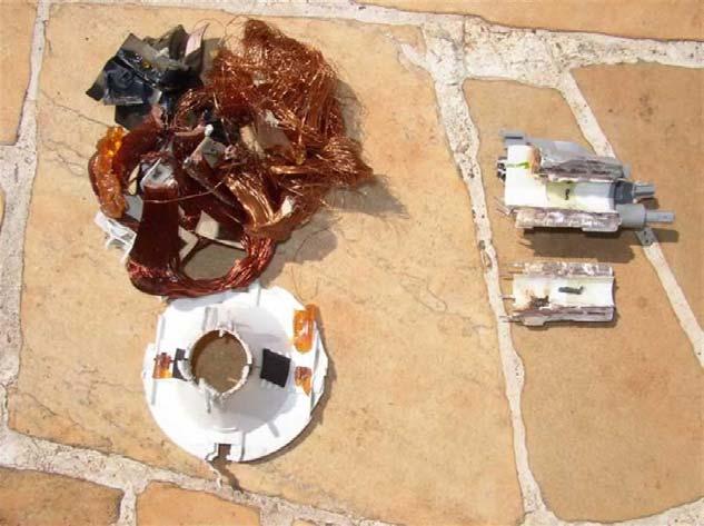
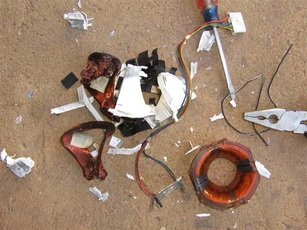
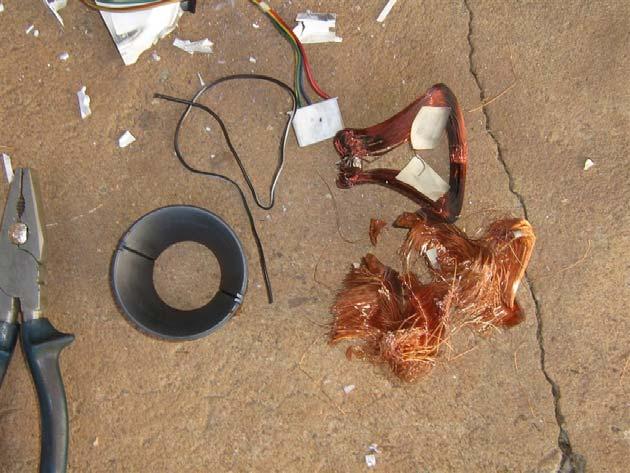
7 use. A current balun will be subjected to much less current through its winding provided a reasonably matched load exists. Losses increase with frequency. For conventional transformer to adapt impedances this is a good choice as it requires less turns for a given inductance. One example would be a Beverage antenna for 160m and/or 80m. Losses must be evaluated though. Another good use for this type of core is in common mode filters for switching power supplies. In such a case the loss may come as an asset. Yoke core: it is expected that a balun with such a core will handle the full legal power. It is recommended to wind with a suitable coaxial cable capable of this much power. For powers up to 100W a good candidate is RG-174. Stacking is always a good option to increase power handling and even the bandwidth as fewer turns are needed for the same inductance, spurious capacitance is also lower. The inductance is proportional to the number of cores and to the square of the number of turns. The W2DU balun consisting of a string of ferrite beads works on this principle, it is a single "turn" of coax cable through a long core. 6 SOME ADDITIONAL POINTERS What happens when the core breaks? One of the fly-back cores broke while I was dismantling it. I simply glued the parts together with cyanocrylate glue. I compared it to a similar, intact unit which measured 1.5 uh with a single pass of wire, the broken core measured 1 uh. This is the result of the gap introduced by the glue thickness. I also measured a core with the original gap as used in the flyback TV transformer, there is a very thin (around 0.2 to 0.4 mm) plastic piece between the two halves, it measured 0.3 uh. See photos 4, 5 and 6.


8 Photos 7, 8 and 9 show the destruction necessary to reach the core! I also used a Dremel tool to make some cuts in some places; The fly-back transformers are generally filled with a though epoxy material.
9
10 On a later date I managed to discover more information regarding ferrites employed in TV sets. An interesting aspect is the resistivity of the materials. High permeability is associated with metallic MnZn mixtures having low resistivity so the core acts as many paralleled resistively shorted turns. Fly-back core resistivity is only 3 ohm/m. Resistivity is strongly frequency-dependent and decreases rapidly with frequency increase. Resistivity is expressed in ohms per metre units or ohms per centimetre units, in table 6 I have converted all that I have collected into ohms/metre units to allow direct comparison. Table 6 Common ferrite materials, their permeability and resistivity Material Permeability Resistivity x10exp3 ohm/m x10exp6 ohm/m ohm/m Yoke 350 1x10exp5 ohm/m Fly-back ohm/m Sabin, W0IYH, reported his measurements of three W2DU current baluns, one with 100 beads of 77 material and inductance 100 uh, other with 100 beads of 43 material, inductance 82 uh and another with 50 larger beads of 43 material for an inductance of 105 uh. He concluded that the high permeability is good for low HF bands but the other two are better overall and tolerate more power. He indicates the need of a balun also at the equipment side as a way to reduce pick-up of household noise. 7 CONCLUSION The yoke core is well suited to HF broadband use in baluns and transformers. The fly-back core is a high permeability material better suited to low HF. These cores can be found for free in repair shops. There's much more to discover as one delves into this subject. For the time being I'm very happy to report these findings and I thank Ian, G3SEK, for his enlightening RadCom note. References: Below is a list of what I consider the most informative texts. Some older publications contain incorrect information based on postulates that were demonstrated to be wrong. "Transmission line transformers", Jerry Sevick, W2FMI, ARRL, "Some aspects of the balun problem", Walter Maxwell, W2DU, QST Mar "Some additional aspects of the balun problem", Roehm, W2OBJ, Antenna Compendium 2, ARRL, "Baluns: what they do and how they do it", Roy Lewallen, W7EL, Antenna Compendium 1, ARRL, "Exploring the 1:1 Current (Choke) Balun", Sabin, William E., W0IYH, QEX July "Designing wideband transformers for HF and VHF Power Amplifiers", Chris Trask, N7ZWY, QEX Mar/Apr 2005.
11 "The 1:1 Current Balun", Roy Lewallen, W7EL: "Balun Balance Quality Test", Tom Rauch, W8JI: Fair-Rite Technical Information: Resistivity:
ARNSW Balun Day. Balun construction
 ARNSW Balun Day Balun construction Typical Baluns All built from locally available components. Balun uses Most baluns are used to match the 50Ω output of a transceiver to an antenna. A centre fed dipole
Jacques Audet VE2AZX. Nov VE2AZX 1
 Jacques Audet VE2AZX VE2AZX@amsat.org Nov. 2006 VE2AZX 1 - REASONS FOR USING A BALUN - TYPES OF BALUNS - CHECK YOUR BALUN WITH AN SWR ANALYZER - MEASURING THE IMPEDANCE OF A NUMBER OF FERRITES - IMPEDANCE
and Related Topics W7KVI, HARC Original: 3/26/16
 Baluns, Ununs, and Related Topics W7KVI, HARC Original: 3/26/16 This Presentation Informal & brisk - 52 slides (too many unless you re an enthusiast!) Discussion encouraged if not extensive, interrupt
Maximize power transfer Reduce feed line loss (if match is at the antenna) Make transmitters happy!
 Make transmitters happy!") Ward Silver - NØAX Impedance = ratio of voltage to current Mechanical analogies Mechanical impedance = ratio of torque to rate of rotation Vehicle transmission is an impedance converter Transfers power
Ward Silver - NØAX Impedance = ratio of voltage to current Mechanical analogies Mechanical impedance = ratio of torque to rate of rotation Vehicle transmission is an impedance converter Transfers power
Clip-on RF Current Meter
 1. Introduction 3. Clip-on RF Current Meter The most useful tool for RF interference troubleshooting! Also in Japanese G0SNO's original article was in RadCom (RSGB) April 1993, page 74. The original Maplin
WCARES NEEDS YOU! CONSIDER MAKING A TECHNICAL PRESENTATION AT AN UPCOMING CHEW & CHAT MEETING LEARN SOMETHING NEW AND PRESENT
 WCARES NEEDS YOU! CONSIDER MAKING A TECHNICAL PRESENTATION AT AN UPCOMING CHEW & CHAT MEETING SHARE WHAT YOU KNOW LEARN SOMETHING NEW AND PRESENT IT CONTACT TIM AD4CJ AD4CJ@arrl.net 1 Transmission Line
Coaxial Transmitting Chokes. Don t Bother Taking Notes
 Coaxial Transmitting Chokes Jim Brown K9YC Santa Cruz, CA http://audiosystemsgroup.com Don t Bother Taking Notes These slides (and a lot more) are at http://audiosystemsgroup.com\publish.htm 1 Why Do We
The design of Ruthroff broadband voltage transformers M. Ehrenfried G8JNJ
 The design of Ruthroff broadband voltage transformers M. Ehrenfried G8JNJ Introduction I started investigating balun construction as a result of various observations I made whilst building HF antennas.
Transmission Line Signal Sampling By Don Steinbach, AE6PM
 Transmission Line Signal Sampling By Don Steinbach, AE6PM When I was finalizing the mechanical layout of my remotely-operated 3-position coaxial antenna switch (Fig. 1), I wanted to include a way to bring
MFJ-219/219N 440 MHz UHF SWR Analyzer TABLE OF CONTENTS
 MFJ-219/219N 440 MHz UHF SWR Analyzer TABLE OF CONTENTS Introduction...2 Powering The MFJ-219/219N...3 Battery Installation...3 Operation Of The MFJ-219/219N...4 SWR and the MFJ-219/219N...4 Measuring
Cray Valley Radio Society. Real Life Wire Antennas
 Cray Valley Radio Society Real Life Wire Antennas 1 The basic dipole The size of an antenna is determined by the wavelength of operation In free space: ~3x10 8 m/s Frequency x Wavelength = Speed of Light,
A short, off-center fed dipole for 40 m and 20 m by Daniel Marks, KW4TI
 A short, off-center fed dipole for 40 m and 20 m by Daniel Marks, KW4TI Version 2017-Nov-7 Abstract: This antenna is a 20 to 25 foot long (6.0 m to 7.6 m) off-center fed dipole antenna for the 20 m and
One I had narrowed the options down, I installed some wire and started testing.
 Loft & Attic antennas for restricted spaces - M. Ehrenfried G8JNJ I ve recently been looking at designs for an efficient antenna that would fit in a loft. I hoped to find something that would work on with
End Fed Half Wave Antenna Coupler
 End Fed Half Wave Antenna Coupler The finished End Fed Half Wave antenna coupler. Centre fed half wave dipoles make great, simple and effective antennas for the HF bands. Sometimes however, the centre
Chokes and Isolation Transformers For Receiving Antennas By Jim Brown K9YC 2018 by James W. Brown All rights reserved
 Chokes and Isolation Transformers For Receiving Antennas By Jim Brown K9YC 2018 by James W. Brown All rights reserved Why We Need Them A feedline must be grounded where it enters the shack-for lightning
Adjust Antenna Tuners Antenna Measurements Capacitor Measurement Measure Feed Point Impedance Measure Ground Loss Inductor Measurement
 The Micro908 antenna analyzer is an extremely useful instrument to have around the ham shack or homebrewer s workbench. This section describes the basic uses, as well as some advanced techniques for which
COAXIAL TRANSMISSION LINE COMMON-MODE CURRENT
 COAXIAL TRANSMISSION LINE COMMON-MODE CURRENT Introduction Coaxial transmission lines are popular for their wide frequency bandwidth and high resistance to electromagnetic interference (EMI). Coax cables
APPLICATION NOTE. A Push-Pull 300 Watt Amplifier for MHz. APT9801 By: Richard Frey, P.E.
 APT9801 By: Richard Frey, P.E. APPLICATION NOTE A Push-Pull 300 Watt Amplifier for 81.36 MHz Reprinted from the April 1998 issue of Applied Microwave and Wireless Magazine courtesy of Noble Publishing
The Fabulous Dipole. Ham Radio s Most Versatile Antenna
 The Fabulous Dipole Ham Radio s Most Versatile Antenna 1 What is a Dipole? Gets its name from its two halves One leg on each side of center Each leg is the same length It s a balanced antenna The voltages
Antenna Design for FM-02
 Antenna Design for FM-02 I recently received my FM-02 FM transmitter which I purchased from WLC. I researched the forum on what antennas where being used by the DIY community and found a nice write-up
Application of Soft Ferrite Material: from EMC to RFID
 Application of Soft Ferrite Material: from EMC to RFID 26 April 2012 Alan Keenan Industrial Electronics GmbH in partnership with HF Technology & Fair-Rite Products Corp. www.fair-rite.com www.ie4u.eu Topics
Antennas and Stuff. John Kernkamp WB4YJT
 Antennas and Stuff John Kernkamp WB4YJT John Kraus W8JK June 28, 1910 - July 18, 2004 Invented the helical antenna, the corner reflector, and the W8JK End-Fire array. In 1950 designed and built the Big
WHY YOU NEED A CURRENT BALUN
 HF OPERATORS WHY YOU NEED A CURRENT BALUN by John White VA7JW NSARC HF Operators 1 What is a Balun? A BALUN is a device typically inserted at the feed point of a dipole-like antenna wire dipoles, Yagi
MFJ-249B HF/VHF SWR ANALYZER
 TABLE OF CONTENTS MFJ-249B... 2 Introduction... 2 Powering The MFJ-249B... 3 Battery Installation... 3 Alkaline Batteries... 3 NiCd Batteries... 4 Power Saving Mode... 4 Operation Of The MFJ-249B...5 SWR
Investigation of the Double-Y Balun for Feeding Pulsed Antennas
 Proceedings of the SPIE, Vol. 5089, April 2003 Investigation of the Double-Y Balun for Feeding Pulsed Antennas Jaikrishna B. Venkatesan a and Waymond R. Scott, Jr. b Georgia Institute of Technology Atlanta,
But this is about practical experiments so lets find out what an inductor is all about.
 Chapter 2 inductors Inductors are components we often use in radio design. We measure them with our LCR meter and build a circuit with them, only to find out the resonance is way off from the calculated
Amateur Extra Manual Chapter 9.4 Transmission Lines
 9.4 TRANSMISSION LINES (page 9-31) WAVELENGTH IN A FEED LINE (page 9-31) VELOCITY OF PROPAGATION (page 9-32) Speed of Wave in a Transmission Line VF = Velocity Factor = Speed of Light in a Vacuum Question
SOME USES FOR RF1,RF5 and VA1 ANALYSTS. SWR Measurement
 SOME USES FOR RF1,RF5 and VA1 ANALYSTS THE HANDIEST INSTRUMENTS IN DECADES! When you put up an antenna in the the old days, it could be a real struggle. The only way to tell if it was tuned to the right
MFJ-834 RF Ammeter. Introduction. Uses
 MFJ-834 RF Ammeter Introduction Congratulations on purchasing the MFJ-834 RF Ammeter. The MFJ-834 is designed for measuring in-line RF feedline current on 1.8-30 MHz while having low interaction on the
Milton Keynes Amateur Radio Society (MKARS)
") Milton Keynes Amateur Radio Society (MKARS) Intermediate Licence Course Feeders Antennas Matching (Worksheets 31, 32 & 33) MKARS Intermediate Licence Course - Worksheet 31 32 33 Antennas Feeders Matching
Milton Keynes Amateur Radio Society (MKARS) Intermediate Licence Course Feeders Antennas Matching (Worksheets 31, 32 & 33) MKARS Intermediate Licence Course - Worksheet 31 32 33 Antennas Feeders Matching
Yana Dongles Tom Berger K1TRB (c)2016 v171227
2016 v171227") Yana Dongles Tom Berger K1TRB (c)2016 v171227 These notes elaborate some items described in the Build notes, and add some more dongles enhancing Yana. Every effort has been exerted to save on the cost
Yana Dongles Tom Berger K1TRB (c)2016 v171227 These notes elaborate some items described in the Build notes, and add some more dongles enhancing Yana. Every effort has been exerted to save on the cost
Design Considerations
 Design Considerations Ferrite beads provide a simple, economical method for attenuating high frequency noise or oscillations. By slipping a bead over a wire, a RF choke or suppressor is produced which
ANTENNA BASICS FOR BEGINNERS
 ANTENNA BASICS FOR BEGINNERS PART 2 -DIPOLES DIPOLES -General MULTIBAND DIPOLES RF CHOKES 1 DIPOLES Several different variations of the dipole are also used, such as the folded dipole, short dipole, cage
A Folding 11-Element Yagi for 432 MHz
 A Folding 11-Element Yagi for 432 MHz Steve Kavanagh, VE3SMA, October 2015 1. Introduction For portable VHF/UHF operation I have found it convenient at times to have some antennas which fold up quickly
The Coaxial Trap Confusion (mostly resolved?)
") The Coaxial Trap Confusion (mostly resolved?) Background Antenna traps need an inductor and a capacitor in a parallel circuit to effectively cut off the end of the antenna for some higher frequency giving
The Coaxial Trap Confusion (mostly resolved?) Background Antenna traps need an inductor and a capacitor in a parallel circuit to effectively cut off the end of the antenna for some higher frequency giving
Some Aspects of the Balun Problem
 Chapter 21 Some Aspects of the Balun Problem (Adapted from QST, March 1983) Sec 21.1 Introduction Why all the mystery surrounding baluns? Here s some straight talk to dispel the rumors! The balun to use,
The Impedance-Transformation Properties of Common 4:1 Balun Types Part 1: Essential Background. L. B. Cebik, W4RNL
 The Impedance-Transformation Properties of Common 4:1 Balun Types Part 1: Essential Background L. B. Cebik, W4RNL One of the most ubiquitous antenna-system accessories among radio amateurs is the 4:1 balun.
Design Considerations
 Design Considerations APPLICATION NOTES: Multi-hole cores provide specialized shapes that are sometimes more useful than single hole devices. One example is wide band transformers where good coupling between
Some Thoughts on Electronic T/R Circuits
 Some Thoughts on Electronic T/R Circuits Wes Hayward, w7zoi, November 3, 2018 Abstract: Several schemes have been used to switch an antenna between a receiver and transmitter. A popular scheme with low
1) Transmission Line Transformer a. First appeared on the scene in 1944 in a paper by George Guanella as a transmission line transformer, the 1:1
 Transmission Line Transformer a. First appeared on the scene in 1944 in a paper by George Guanella as a transmission line transformer, the 1:1") 1) Transmission Line Transformer a. First appeared on the scene in 1944 in a paper by George Guanella as a transmission line transformer, the 1:1 Guanella Balun is the basic building Balun building block.
1) Transmission Line Transformer a. First appeared on the scene in 1944 in a paper by George Guanella as a transmission line transformer, the 1:1 Guanella Balun is the basic building Balun building block.
VE7CNF - 630m Antenna Matching Measurements Using an Oscilloscope
 VE7CNF - 630m Antenna Matching Measurements Using an Oscilloscope Toby Haynes October, 2016 1 Contents VE7CNF - 630m Antenna Matching Measurements Using an Oscilloscope... 1 Introduction... 1 References...
What causes the Out-of-Balance Current in the coax and why does it Radiate?
 The EH Antenna - Out of Balance Current or Longitudinal Mode Current in the Coaxial Cable causes radiation from the coax. But how large a proportion of the total power is radiated or lost from this Current?
Technician License. Course
 Technician License Course Technician License Course Chapter 4 Lesson Plan Module - 9 Antenna Fundamentals Feed Lines & SWR The Antenna System The Antenna System Antenna: Transforms current into radio waves
Build a Return Loss Bridge
 Build a Return Loss Bridge Used with your DVM, this simple bridge, diode detector and return loss techniques can help you measure cable loss and SWR at the antenna. The bridge does double duty as a hybrid
Chapter 6 Antenna Basics. Dipoles, Ground-planes, and Wires Directional Antennas Feed Lines
 Chapter 6 Antenna Basics Dipoles, Ground-planes, and Wires Directional Antennas Feed Lines Some General Rules Bigger is better. (Most of the time) Higher is better. (Most of the time) Lower SWR is better.
Homebrew and Experimenters Group HF Inductance Bridge (Compiled by VK2TOX)
") Homebrew and Experimenters Group HF Inductance Bridge (Compiled by VK2TOX) There are a number of ways to measure inductances used in construction of RF equipment. One of the most versatile ways is with
Homebrew and Experimenters Group HF Inductance Bridge (Compiled by VK2TOX) There are a number of ways to measure inductances used in construction of RF equipment. One of the most versatile ways is with
Reference Design for MHz Push-Pull 600 W RF Amplifier IXZ318N50L
 1609 Oakridge Drive, Suite 100 Fort Collins, CO. 80525 (970) 493-1901 www.ixyscolorado.com Reference Design for 13.56 MHz Push-Pull 600 W RF Amplifier IXZ318N50L Martin Jones R&D/Application Engineering
Portable Vertical Antenna for 75m & 40m
 Portable Vertical Antenna for 75m & 40m BOXBORO August 2012 Jacques VE2AZX Web: ve2azx.net 1 Objectives 1- Portable Antenna for 75m et 40m 2- Low radiation angle for DX 3- Efficient 4- Easy to install.
The Crashcup 1V40 1W Transmitter
 The Crashcup 1V40 1W Transmitter by Chris Trask / N7ZWY Sonoran Radio Research P.O. Box 25240 Tempe, AZ 85285-5240 Email: christrask@earthlink.net 7 January 2009 Trask, Crashcup 1V40 1 7 January 2009 Introduction
Why all the mystery surrounding baluns?
 Chapter 21 Some Aspects of The Balun Problem (Adapted from QST, March 1983) Sec 21.1 Introduction Why all the mystery surrounding baluns? Here's some straight talk to dispel the rumors! The balun to use,
G6ALU 20W FET PA Construction Information
 G6ALU 20W FET PA Construction Information The requirement This amplifier was designed specifically to complement the Pic-A-Star transceiver developed by Peter Rhodes G3XJP. From the band pass filter an
Adapting a 160m Inverted-L for 630m
 Adapting a 160m Inverted-L for 630m In 2017 the FCC opened up the 630m and 2200m bands for Amateur Radio use with some minor conditions as explained in this ARRL article http://www.arrl.org/news/new-bands-fcc-issues-amateurradio-service-rules-for-630-meters-and-2-200-meters.
What is a BALUN or UNUN:
 What is a BALUN or UNUN: A device to connect different types of antennas to various feed lines. Can transform impedances, choke common mode or change balanced to unbalanced BALUN Balanced to Unbalanced
A TRANSMISSION LINE BALANCE TEST METER
 by Lloyd Butler VK5BR with modifications by Phil Storr VK5SRP. Here is a simple meter to check the balance of currents running in the two legs of a transmission line. It can be used to check the balance
The Principle V(SWR) The Result. Mirror, Mirror, Darkly, Darkly
 The Result. Mirror, Mirror, Darkly, Darkly") The Principle V(SWR) The Result Mirror, Mirror, Darkly, Darkly 1 Question time!! What do you think VSWR (SWR) mean to you? What does one mean by a transmission line? Coaxial line Waveguide Water pipe Tunnel
The Principle V(SWR) The Result Mirror, Mirror, Darkly, Darkly 1 Question time!! What do you think VSWR (SWR) mean to you? What does one mean by a transmission line? Coaxial line Waveguide Water pipe Tunnel
Intermediate Course (5) Antennas and Feeders
 Antennas and Feeders") Intermediate Course (5) Antennas and Feeders 1 System Transmitter 50 Ohms Output Standing Wave Ratio Meter Antenna Matching Unit Feeder Antenna Receiver 2 Feeders Feeder types: Coaxial, Twin Conductors
Intermediate Course (5) Antennas and Feeders 1 System Transmitter 50 Ohms Output Standing Wave Ratio Meter Antenna Matching Unit Feeder Antenna Receiver 2 Feeders Feeder types: Coaxial, Twin Conductors
HF Balanced Transmitting Systems
 HF Balanced Transmitting Systems A compendium extracted from published material Revision 1.2 11/18/2005 Page 1 of 75 Contents Coupling The Transmitter To The Aether... 3 W0IYH Feedline Choke Performance...
Technician License Course Chapter 4. Lesson Plan Module 9 Antenna Fundamentals, Feed Lines & SWR
 Technician License Course Chapter 4 Lesson Plan Module 9 Antenna Fundamentals, Feed Lines & SWR The Antenna System Antenna: Transforms current into radio waves (transmit) and vice versa (receive). Feed
Feed Line Currents for Neophytes.
 Feed Line Currents for Neophytes. This paper discusses the sources of feed line currents and the methods used to control them. During the course of this paper two sources of feed line currents are discussed:
Basic Wire Antennas. Part II: Loops and Verticals
 Basic Wire Antennas Part II: Loops and Verticals A loop antenna is composed of a single loop of wire, greater than a half wavelength long. The loop does not have to be any particular shape. RF power can
The Balun and The UNUN - page 1
 The Balun and The UNUN - page 1 When is a Balun, not a balun, when it is an UNUN! Balun = "BALanced-to-UNbalanced" Unun = "UNbalanced-to-UNbalanced" Looking at the two diagrams above you will see the common
A Folding 5-Element Yagi for 144 MHz
 A Folding 5-Element Yagi for 144 MHz Steve Kavanagh, VE3SMA, April 2017 1. Introduction I have found antennas which fold up quickly to take less space in the car to be useful in VHF/UHF portable operating.
A IVE-BAND, TWO-ELEMENT H QUAD
 A IVE-BAND, TWO-ELEMENT H QUAD Two quad designs are described in this article, both nearly identical. One was constructed by KC6T from scratch, and the other was built by Al Doig, W6NBH, using modified
Technician License. Course
 Technician License Course Technician License Course Chapter 4 Lesson Plan Module - 10 Practical Antennas The Dipole Most basic antenna The Dipole Most basic antenna The Dipole Total length is ½ wavelength
Build a 12/17 Meter Trap Dipole Phil Salas AD5X
 Build a 12/17 Meter Trap Dipole Phil Salas AD5X Introduction Why a 12/17 meter rotatable dipole? Well, many folks have verticals for the lower bands, and multi-band dipoles or beams for 20-, 15-, and 10
The Amazing MFJ 269 Author Jack Tiley AD7FO
 The Amazing MFJ 269 Author Jack Tiley AD7FO ARRL Certified Emcomm and license class Instructor, Volunteer Examiner, EWA Technical Coordinator and President of the Inland Empire VHF Club What Can be Measured?
Understanding and Eliminating RF Interference
 Understanding and Eliminating RF Interference Jim Brown K9YC Audio Systems Group, Inc. http://audiosystemsgroup.com Basic Interference Mechanisms Audio cables are antennas Pin 1 problems Shield-current-induced
ANTENNAS. I will mostly be talking about transmission. Keep in mind though, whatever is said about transmission is true of reception.
 Reading 37 Ron Bertrand VK2DQ http://www.radioelectronicschool.com ANTENNAS The purpose of an antenna is to receive and/or transmit electromagnetic radiation. When the antenna is not connected directly
TBARC Programs Antenna Modeling with 4NEC2. By Randy Rogers AD7ZU 2010
 TBARC Programs Antenna Modeling with 4NEC2 By Randy Rogers AD7ZU 2010 Getting Started 4NEC2 is a completely free windows based tool suite to aid in the design and optimization of antenna systems 4NEC2
L. B. Cebik, W4RNL. Basic Transmission Line Properties
 L. B. Cebik, W4RNL In the course of developing this collection of notes, I have had occasion to use and to refer to both series and parallel coaxial cable assemblies. Perhaps a few notes specifically devoted
Beams and Directional Antennas
 Beams and Directional Antennas The Horizontal Dipole Our discussion in this chapter is about the more conventional horizontal dipole and the simplified theory behind dipole based designs. For clarity,
MAGNETIC LOOP SYSTEMS SIMPLIFIED
 MAGNETIC LOOP SYSTEMS SIMPLIFIED By Lez Morrison VK2SON Many articles have been published and made available on websites recently. Unfortunately they have tended to make construction sound complicated
A Four-Decade Bandwidth Hybrid Coupler
 EUROPEAN ORGANIZATION FOR NUCLEAR REEARCH CERN AB DEPARTMENT P/BD Note 99 AB-Note-6-5 BI A Four-Decade Bandwidth Hybrid Coupler J.M. Belleman Abstract A hybrid coupler is a reciprocal radio-frequency building
Using Ferrite Beads Keep RF Out of TV Sets, Telephones, VCR's Burglar Alarms and other Electronic Equipment
 Using Ferrite Beads Keep RF Out of TV Sets, Telephones, VCR's Burglar Alarms and other Electronic Equipment RFI and TVI have been with us for a long time. Now we have microwave ovens, VCR's and many other
Chapter 2. The Fundamentals of Electronics: A Review
 Chapter 2 The Fundamentals of Electronics: A Review Topics Covered 2-1: Gain, Attenuation, and Decibels 2-2: Tuned Circuits 2-3: Filters 2-4: Fourier Theory 2-1: Gain, Attenuation, and Decibels Most circuits
HF Amateur SSB Receiver
 HF Amateur SSB Receiver PCB Set for radio club project http://rhelectronics.net PCB for DIY HF Amateur SSB Receiver 20M The receiver is a simple syperheterodyne type with quartz crystal filter. The circuit
The Balun and The UnUn - page 1
 The Balun and The UnUn - page 1 When is a Balun, not a Balun, when it is an UnUn! Balun = "Balanced-to-Unbalanced" UnUn = "Unbalanced-to-Unbalanced" Looking at the two diagrams above you will see the common
How to Blow Up Your Balun
 How to Blow Up Your Balun (and other things too ) By Dean Straw, N6BV Sea-Pac June 7, 2014 Photos courtesy Jim Brown, K9YC 1 This is What I Intend to do Today I will examine stresses placed on common-mode
Stand Alone RF Power Capabilities Of The DEIC420 MOSFET Driver IC at 3.6, 7, 10, and 14 MHZ.
 Abstract Stand Alone RF Power Capabilities Of The DEIC4 MOSFET Driver IC at 3.6, 7,, and 4 MHZ. Matthew W. Vania, Directed Energy, Inc. The DEIC4 MOSFET driver IC is evaluated as a stand alone RF source
Coaxial Cable Feeder Influence on Four Stacked Yagi Antennas Array Dragoslav Dobričić, YU1AW
 Coaxial Cable Feeder Influence on Four Stacked Yagi Antennas Array Dragoslav Dobričić, YU1AW dragan@antennex.com Introduction Aprevious article series consisted of two parts [1, 2] showing the results
New Understandings of the Use of Ferrites in the Prevention and Suppression of RF Interference to Audio Systems
 New Understandings of the Use of Ferrites in the Prevention and Suppression of RF Interference to Audio Systems Jim Brown Audio Systems Group, Inc. Chicago, IL, 60640 USA jim@audiosystemsgroup.com This
This paper is meant assist in the operation and understanding of the VIA Bravo Family of products.
 Abstract: This paper is meant assist in the operation and understanding of the VIA Bravo Family of products. Understanding the Display and its Readings: The VIA Bravo display provides graphical and numerical
Baluns: What They Do And How They Do It
 Baluns: What They Do And How They Do It By Roy W. Lewallen,* W7EL *5470 SW 152nd Ave., Beaverton, OR 97007 I've always been a bit bothered by baluns, since I was never sure what they are supposed to do,
160- and 80-Meter Matching Networks for your 43-foot Vertical Phil Salas AD5X
 160- and 80-Meter Matching Networks for your 43-foot Vertical Phil Salas AD5X 43-foot verticals have become popular as they can be self supporting, are not too obtrusive, and have higher radiation resistance
WA4DXP. Mobile Antennas. Mounts, Antennas, Tuners (or not) & grounding Presented by M.D. Smith
 & grounding Presented by M.D. Smith") WA4DXP Mobile Antennas Mounts, Antennas, Tuners (or not) & grounding Presented by M.D. Smith Mounts Mobile Antennas WA4DXP Bolt on antenna mount... Same as used on heavy truck mirror mount Sheet metal
WA4DXP Mobile Antennas Mounts, Antennas, Tuners (or not) & grounding Presented by M.D. Smith Mounts Mobile Antennas WA4DXP Bolt on antenna mount... Same as used on heavy truck mirror mount Sheet metal
AD5X. The 43-Foot Vertical. Phil Salas - AD5X Phil Salas AD5X. Richardson, Texas
 The 43-Foot Vertical Phil Salas - AD5X ad5x@arrl.net Outline Why a vertical? Ground Losses and Antenna Efficiency Why a 43-foot vertical? SWR-related coax and unun losses Matching Networks for 160- and
SWL Receiving Antenna Experiments
 SWL Receiving Antenna Experiments Introduction I have a lot to learn about SWL antennas. What follows are some brief experiments I performed in late October 2005. I have been experimenting with a half
Homebrew your Omnidirectional INMARSAT-C Antenna
 Homebrew your Omnidirectional INMARSAT-C Antenna In this short article we are going to look into the construction details of an old commercial INMARSAT-C Antenna. The purpose of this document is to serve
Least understood topics by most HAMs RF Safety Ground Antennas Matching & Feed Lines
 Least understood topics by most HAMs RF Safety Ground Antennas Matching & Feed Lines Remember this question from the General License Exam? G0A03 (D) How can you determine that your station complies with
EVERY rotor control, remote antenna selector also has a common mode choke at each end of the cable!
 Radio Communication Choosing a Coax Feed Line Choke By Bob Brehm, AK6R RFI Tip Sheet #RC-1 How to choose feed line chokes, line isolators, baluns, or ununs for coax fed dipoles, verticals, hex beams, slopers,
A Transmatch for Balanced or Unbalanced Lines
 A Transmatch for Balanced or Unbalanced Lines Most modern transmitters are designed to operate into loads of approximately 50 Ω. Solid-state transmitters produce progressively lower output power as the
RFID. Technical Training. Low Frequency Antenna Design. J.A.G Jan 2009 Texas Instruments Proprietary Information 1
 Technical Training Low Frequency Antenna Design J.A.G Jan 2009 Texas Instruments Proprietary Information 1 Custom Antenna Design There are many reasons why integrators may wish to make their own Low Frequency
Antenna Matching Within an Enclosure Part II: Practical Techniques and Guidelines
 Antenna Matching Within an Enclosure Part II: Practical Techniques and Guidelines By Johnny Lienau, RF Engineer June 2012 Antenna selection and placement can be a difficult task, and the challenges of
Development of a noval Switched Beam Antenna for Communications
 Master Thesis Presentation Development of a noval Switched Beam Antenna for Communications By Ashraf Abuelhaija Supervised by Prof. Dr.-Ing. Klaus Solbach Institute of Microwave and RF Technology Department
LC31L-BAT Link Coupler
 Instruction Manual For the LC31L-BAT Link Coupler 09 March 2018 2012-2018 by Ralph Hartwell Spectrotek Services All rights reserved 2 RADIO FREQUENCY WARNING NOTICE If the LC31L-BAT is installed incorrectly
Owen Duffy VK2OMD owenduffy.net
 Owen Duffy VK2OMD owenduffy.net owen@owenduffy.net Antenna system Differential and common mode feed line current Balun types and characteristics Insights from NEC models, measurements Example application:
Stack Match. Photo.1 Circuit diagram
 Stack Match Photo.1 Circuit diagram Stack Match matches the input impedance of 50 Ω; via broadband Impedance matching transformer with output impedance 22.25 Ω for 3 YAGI antennas in a vertical stack.
The University of New South Wales. School of Electrical Engineering and Telecommunications. High Voltage Systems ELEC9712. Appendix Partial Discharge
 The University of New South Wales School of Electrical Engineering and Telecommunications High Voltage Systems ELEC9712 Appendix Partial Discharge Content Introduction Quantities measured Test circuits
Iron Powder Cores for High Q Inductors By: Jim Cox - Micrometals, Inc.
 HOME APPLICATION NOTES Iron Powder Cores for High Q Inductors By: Jim Cox - Micrometals, Inc. SUBJECT: A brief overview will be given of the development of carbonyl iron powders. We will show how the magnetic
RFI and Ferrites. Jim Brown K9YC Audio Systems Group, Inc. Santa Cruz. Primary Interference Mechanisms
 RFI and Ferrites Jim Brown K9YC Audio Systems Group, Inc. Santa Cruz jim@audiosystemsgroup.com Primary Interference Mechanisms Common-mode noise on signal wiring Pin 1 problems Improper shield termination