A Folding 5-Element Yagi for 144 MHz
|
|
|
- Bruce Mitchell
- 6 years ago
- Views:
Transcription
1 A Folding 5-Element Yagi for 144 MHz Steve Kavanagh, VE3SMA, April Introduction I have found antennas which fold up quickly to take less space in the car to be useful in VHF/UHF portable operating. For some years I have had a 4-element 2m Yagi along with me on VHF contest trips, which folds up to fit in the back of my Toyota Matrix. While there have been many designs published for 2m beams which can be dismantled for backpacking, I haven t seen any which can be assembled in a few seconds, which is desirable for those of us entering the Rover classes in VHF contests and don t want to drive with the antennas up all the time. My old 4- element antenna does this, and fits right in front of a 6m dipole, but doesn t have a lot of gain or good SWR over very much of the band. An improved version was called for. I get about 1.5 db more gain from this new 5-element design and decent SWR up to about 147 MHz. Plus it still fits in the same space in the car. 2. Dimensions Element diameter: 3/16 inch (solid aluminum parasitic elements, brass tubing for driven element) Boom: ¾ thick pine (made from 1X2), total boom length 52 inches, folds to 26 inches Boom depth (top-to-bottom): Mostly about 0.8 inch, tapering up to 1.5 inch at mounting clamp and hinge Tolerances: I tried to stay within ±2 mm on element positions, about ±1 mm for element lengths Length Corrections: No boom correction factor is applied to the element lengths and it should not be necessary with a wood boom of this thickness. The parasitic element lengths were adjusted according to a simple formula [1] for solid elements, while the tubular driven element was not corrected. Element Distance from rear end of boom (mm) Distance from forward end of boom (mm) Element length in NEC model (mm) End correction (mm) [1] Actual element length (mm) Reflector Driven Element (at centre) (see details below) (none) (each half, see below) Director Director Director
2 3. Boom Details Refer to the sketch below. The boom is made from 1x2 pine (actually ¾ x 1-1/2 ). The front part is 660 mm long (from the hinge point to the tip). The rear part is made up from 4 pieces. The main part is mm long, from the hinge point to the gap for the driven element. There are two driven element mounting blocks and a reflector support piece (276.6 mm long) also made from ¾ thick pine, arranged to provide a 25 mm gap around the driven element and a total rear part length of 660 mm (from the hinge point to the rear end of the boom). The lengths of the driven element mounting blocks is not critical, but they need to be long enough that their joints with the main and reflector mounting parts of the boom are strong enough, but short enough to keep clear of the reflector and first director. In general the boom cross-section is 0.75 x 0.80 inch, but near the hinge point the depth of each part is tapered from 0.8 inch up to the full 1.5 inch dimension of the 1X2 in order to provide a place to attach a mounting clamp and to ensure that the boom is straight when opened out. The rear part pieces are joined together with wood glue and 1/4" inch dowels through all three pieces, with two dowels on each side of the driven element. The hinge is a 2 inch strap hinge fastened to the tops of the boom sections with wood screws (drill pilot holes first to avoid splitting the wood). I found it necessary to tighten the hinge before mounting it to the boom (by squeezing it carefully with vice-grips) to avoid too much wobble. The boom is drilled (using a 3/16 diameter bit) for each of the elements at the positions given in the table. The elements are epoxied into place with a small fillet of epoxy where they exit the wood. The boom is then painted or varnished. Don t paint the elements unless you know very well the RF properties of the paint! A TV-antenna-type U-bolt clamp is used to mount the antenna to the mast, with the original nuts replaced with wing nuts for quick assembly without tools.
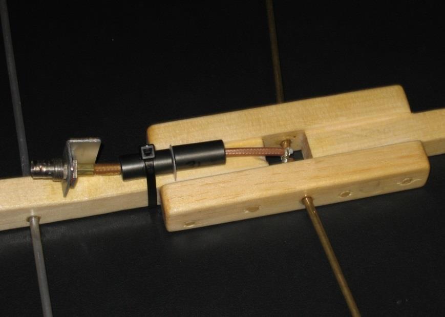
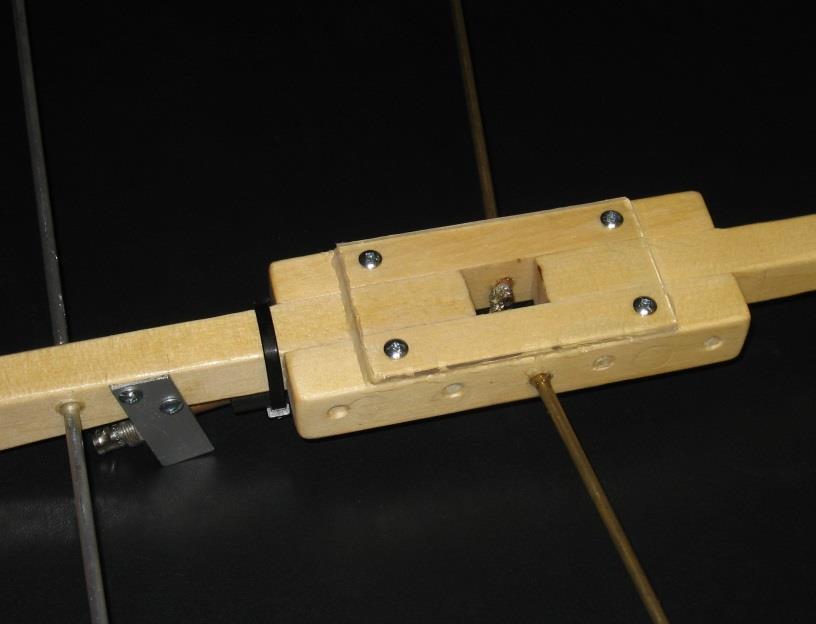
3 4. Driven Element Details See the following figure. A bent dipole driven element is used for matching and control of coupling to the nearby elements, as introduced by K6STI and developed and described in more detail by DG7YBN [2]. The element halves are inserted in 3/16 holes (drilled at an angle) in the mounting blocks such that there is a 4mm gap between their inner ends. Dimensions of the driven element half are to the centre line of the tubing. The driven element should be soldered to the coaxial cable, and then epoxied in place. 5. Balun and Connector I put two inch long by O.D. by I.D. Type 31 ferrite beads on the coax near the driven element to reduce current flowing on the outside of the coaxial cable. This should be adequate up to about 100 watts. On another antenna I have used 3 beads at 300 watts (CW, SSB and JT65). You can see the ferrite beads in the photos, under the boom between the connector and the driven element, with a small plastic spacer between them that I hope will reduce the chance of breakage (ferrite is brittle). After the varnish was dry I fastened the ferrite beads to the boom with a cable tie. I used a female BNC connector mounted on a bracket made from aluminum angle. An alternate would be to simply put your favourite connector on a dangling pigtail of coax (taped or cabletied to the boom to relieve stress at the connection to the driven element).


4 6. Feed Cover The boom gap at the feed point is protected from rain by a small piece of Plexiglas (any rigid plastic or thin wood would probably do) which is held in place with screws into the boom. I sealed the edges with silicone sealant. 7. Photographs

5
6 8. Predicted Performance Software: 4NEC2 File: BentDEYagi23j.nec Assumptions: No conductor loss, no balun loss. Note that the driven element geometry is slightly different in the model, to accommodate NEC limitations. SWR/Return Loss: Gain/Front-to-back ratio/front-to rear ratio:
7 Radiation patterns at MHz:
8 9. Measured Performance The initial SWR measurement was done using a Bird 43 Wattmeter with a 50C element and about 25 watts transmitter power. The antenna was at the far end of 25 feet of RG-8/M coaxial cable. The SWR values were corrected for the estimated loss of the cable. I have not had an opportunity to get the gain measured. This antenna was used in my winning June 2016 ARRL VHF Contest Rover entry (with VE3RZ) and performed as expected with no problems. 10. References [1] [2]
A Folding 11-Element Yagi for 432 MHz
 A Folding 11-Element Yagi for 432 MHz Steve Kavanagh, VE3SMA, October 2015 1. Introduction For portable VHF/UHF operation I have found it convenient at times to have some antennas which fold up quickly
9 Element Yagi for 2304 MHz
 9 Element Yagi for 2304 MHz Steve Kavanagh, VE3SMA Design Dipole-based Yagi designs for 2304 MHz are rare, partly because they are a bit tricky to build and partly because the loop yagi has completely
Cushcraft. Amateur Radio Antennas LFA-6M5EL. 6 Meter 5 Element Loop Feed Antenna INSTRUCTION MANUAL
 Cushcraft Amateur Radio Antennas LFA-6M5EL 6 Meter 5 Element Loop Feed Antenna INSTRUCTION MANUAL CAUTION: Read All Instructions Before Operating Equipment VERSION 1A Cushcraft Amateur Radio Antennas 308
Technician License. Course
 Technician License Course Technician License Course Chapter 4 Lesson Plan Module - 10 Practical Antennas The Dipole Most basic antenna The Dipole Most basic antenna The Dipole Total length is ½ wavelength
Construction manual for 50 MHz XL design yagi-kits
 Construction manual for 50 MHz XL design yagi-kits Source: http://www.nuxcom.de/pdf/nuxcom_construction-manual_6m-xl.pdf Please check if all parts listed in the invoice are delivered with the kit. In the
INSTRUCTION MANUAL. Specifications Electrical. Front-To-Back Ratio VSWR at Resonance Less than 1.5:1 Nominal Impedance. Mechanical
 300 Industrial Park Road, Starkville, MS 39759 Ph: (662) 323-8538 FAX: (662) 323-6551 TH-3JRS Tri-band HF 3 Elements Beam Covers 10, 15 and 20 Meters INSTRUCTION MANUAL WARNING Installation of this product
Cushcraft. Amateur Radio Antennas DB-46M8EL. Dual band 6 and 4 Meter, 8 Element Beam Antenna INSTRUCTION MANUAL
 Cushcraft Amateur Radio Antennas DB-46M8EL Dual band 6 and 4 Meter, 8 Element Beam Antenna INSTRUCTION MANUAL CAUTION: Read All Instructions Before Operating Equipment VERSION 1B Cushcraft Amateur Radio
Directive Systems & Engineering 2702 Rodgers Terrace Haymarket, VA
 Directive Systems & Engineering 2702 Rodgers Terrace Haymarket, VA 20169-1628 www.directivesystems.com 703-754-3876 25 Element 7.4 wl. K1FO Designed Yagi, Model DSEFO432-25 ELECTRICAL SPECIFICATIONS Frequency
Portable or Emergency VHF Antennas Paul R. Jorgenson KE7HR
 For emergency or public service events it is often necessary to have more antenna than the rubber duck on your handheld VHF radio. Nearly ANY external antenna will provide more coverage for your handheld
MI: (Secure this number someplace, for possible future need) SPECIFICATIONS:
 SPECIFICATIONS:") 6C ASSEMBLY INSTRUCTIONS ANTENNA MODEL T6 MI: 030927 (Secure this number someplace, for possible future need) SPECIFICATIONS: FORWARD GAIN 5.1 dbd F:B RATIO 15-25 db (Rises with frequency) FREQUENCY COVERAGE
6C ASSEMBLY INSTRUCTIONS ANTENNA MODEL T6 MI: 030927 (Secure this number someplace, for possible future need) SPECIFICATIONS: FORWARD GAIN 5.1 dbd F:B RATIO 15-25 db (Rises with frequency) FREQUENCY COVERAGE
MODEL DB-1015A 10- and 15-Meter Duo-Band Antenna Order No. 330
 MODEL DB-1015A 10- and 15-Meter Duo-Band Antenna Order No. 330 HY-GAIN ELECTRONICS CORPORATION 8601 Northeast Highway 6 Lincoln, Nebraska 68505 Telephone 464-9151 Area Code 402 TABLE OF CONTENTS page SECTION
Model VB-23FM 2-Meter 3-Element Beam
 308 Industrial Park Road Starkville, MS 39759 USA Ph: (662) 323-9538 FAX: (662) Model VB-23FM 2-Meter 3-Element Beam [ INSTRUCTION MANUAL Figure 1 Overall View and Boom Detail GENERAL DESCRIPTION This
MFJ-1762 Instruction Manual
 MFJ-1762 Instruction Manual INTRODUCTION Thank you for purchasing the MFJ-1762 three-element six-meter Yagi. The MFJ-1762 is a light-weight directional antenna especially designed for installation with
MOUNTING INSTRUCTIONS
 Standard Mounting Bracket Tilting Bracket* Mounting example Right side for upper tilt from 0 to 20 20 Spare parts: p/n SA197 Materials: extruded aluminum Hardware: stainless & zinc plated steel Dimensions
LJ element beam for 10 or 12 meters INSTRUCTION MANUAL. CAUTION: Read All Instructions Before Operating Equipment
 LJ-113 3 element beam for 10 or 1 meters INSTRUCTION MANUAL CAUTION: Read All Instructions Before Operating Equipment 308 Industrial Park Road Starkville, MS 39759 USA Tel: 66-33-9538 Fax: 66-33-6551 VERSION
INSTRUCTION MANUAL. Specifications Mechanical. 1 5/8 to 2 1/16 O.D. (41mm to 52mm)
") 308 Industrial Park Road Starkville, MS 39759 USA Ph: (662) 323-9538 FAX: (662) 323- General Description Model VB-25FM 2-Meter 5 Elements Beam INSTRUCTION MANUAL This antenna is a 5-element, 2-meter beam
308 Industrial Park Road Starkville, MS 39759 USA Ph: (662) 323-9538 FAX: (662) 323- General Description Model VB-25FM 2-Meter 5 Elements Beam INSTRUCTION MANUAL This antenna is a 5-element, 2-meter beam
M2 Antenna Systems, Inc. Model No: YAGI ANTENNA
 M Antenna Systems, Inc. Model No: 4.5-7 YAGI ANTENNA SPECIFICATIONS: Model... 4.5-7 Frequency Range... 4.0 To 4.5 MHz *Gain... 0 To 7 dbi Front to back... 0 db over the rear 80 Beamwidth... E=44 H=50 typical
INSTRUCTION MANUAL for MODEL TH6-DX "THUNDERBIRD" (389)
") INSTRUCTION MANUAL for MODEL TH6-DX "THUNDERBIRD" (389) HY-GAIN ELECTRONICS CORPORATION, N. E. Hwy #6 at Stevens Creek, Lincoln, Nebraska 65801 Telephone 434-6331 INTRODUCTION Ely-Gain's new Model TH6-DX
INSTRUCTION MANUAL for MODEL TH6-DX "THUNDERBIRD" (389) HY-GAIN ELECTRONICS CORPORATION, N. E. Hwy #6 at Stevens Creek, Lincoln, Nebraska 65801 Telephone 434-6331 INTRODUCTION Ely-Gain's new Model TH6-DX
Hy-gain. Method 1 : Completely assemble the antenna on the ground then hoist it into position using a setup as shown in Figure 1.
 Hy-gain The Hy-Gain TH6-DXX "Super Thunderbird" is a 6-element beam designed to operate on 10, 25 and 20 meters. It has four active elements on 10-meters and three active elements on 15 and 20 meters.
TELEX. iiilhiijiri INSTRUCTION MANUAL ORDER NO. 411 TELEX COMMUNICATIONS, INC ALDRICH AVE SO. MINNEAPOLIS. MN U.SA.
 TELEX. iiilhiijiri TELEX COMMUNICATIONS, INC. 9600 ALDRICH AVE SO. MINNEAPOLIS. MN 55420 U.SA. INSTRUCTION MANUAL ORDER NO. 411 Base Station, 5-Element Beam Antenna This antenna is a five element, Citizens
Directive Systems & Engineering 2702 Rodgers Terrace Haymarket, VA
 Directive Systems & Engineering 2702 Rodgers Terrace Haymarket, VA 20169 1628 www.directivesystems.com 703 754 3876 K1JX DESIGNED 6 ELEMENT 50 MHZ YAGI, DSEJX6 50 INTRODUCTION The Directive Systems DSEJX6-50
TZ-RD-1740 Rotary Dipole Instruction Manual
 TZ-RD-1740 17/40m Rotary Dipole Instruction Manual The TZ-RD-1740 is a loaded dipole antenna for the 40m band and a full size rotary dipole for the 17m band. The antenna uses an aluminium radiating section
TELEX, liutiiilio"i TELEX COMMUNICATIONS, INC ALDRICH AVE. SO. MINNEAPOLIS. MN USA
 TELEX, liutiiilio"i TELEX COMMUNICATIONS, INC. 9600 ALDRICH AVE. SO. MINNEAPOLIS. MN 55420 USA INSTRUCTION MANUAL ORDER NO. 410 General This antenna is a five-element, Citizens Band beam with a forward
A HIGH PERFORMANCE AIRBAND ANTENNA FOR YOUR ULTRALIGHT / LIGHTSPORT AIRCRAFT by Dean A. Scott (revised March, 2018)
") A HIGH PERFORMANCE AIRBAND ANTENNA FOR YOUR ULTRALIGHT / LIGHTSPORT AIRCRAFT by Dean A. Scott (revised March, 2018) In this article I present a simple, easy to construct, and easy to mount Inverted V halfwave
A HIGH PERFORMANCE AIRBAND ANTENNA FOR YOUR ULTRALIGHT / LIGHTSPORT AIRCRAFT by Dean A. Scott (revised March, 2018) In this article I present a simple, easy to construct, and easy to mount Inverted V halfwave
THE W3FF HOMEBREW BUDDIPOLE
 THE W3FF HOMEBREW BUDDIPOLE A PORTABLE ANTENNA DESIGN FOR AMATEUR RADIO History of the Buddipole In January of 2000, I began experimenting with a walking portable ham station. Since then, thousands of
The W3FF Portable Dipole
 The W3FF Portable Dipole This is the antenna I designed for my 'walking portable' station. It is a dipole constructed out of the plastic plumbing pipe CPVC. There are telescoping whips at the ends of each
VHF and UHF Antennas for QRP Portable Operation. Prepared for the QRP forum at Pacificon2011 by KK6MC James Duffey October 15, 2011
 VHF and UHF Antennas for QRP Portable Operation Prepared for the QRP forum at Pacificon2011 by KK6MC James Duffey October 15, 2011 Overview Get on the air from portable locations with simple and effective
Long ago, I used to build 4m antennas using fishplates to mount ½ diameter elements onto a 1 round boom. The fishplates were sheet aluminium
 Long ago, I used to build 4m antennas using fishplates to mount ½ diameter elements onto a 1 round boom. The fishplates were sheet aluminium pressings made by a local distributor of broadcast radio & TV
M2 Antenna Systems, Inc. Model No: 20M5LD
 M2 Antenna Systems, Inc. Model No: 20M5LD SPECIFICATIONS: Model... 20M5LD Frequency Range... 14.0 14.350 MHz *Gain (Full Band)... 10.2 dbi Typical Front to back... 23 db Typical Beamwidth... E=50 / H=66
Mast and Antennas for Field Day & Emergencies
 Mast and Antennas for Field Day & Emergencies John A. Allocca, WB2LUA, July 2005 This is a 27 feet 1.5 diameter portable guyed mast with a 28 feet diameter footprint. It breaks down into four 6 feet sections
M2 Antenna Systems, Inc. Model No: 2M7
 M2 Antenna Systems, Inc. Model No: 2M7 SPECIFICATIONS: Model... 2M7 Frequency Range... 144 To 148 MHz *Gain... 12.3 dbi Front to back... 20 db Typical Beamwidth... E=43 H=50 Feed type... T Match Feed Impedance....
4 Antennas as an essential part of any radio station
 4 Antennas as an essential part of any radio station 4.1 Choosing an antenna Communicators quickly learn two antenna truths: Any antenna is better than no antenna. Time, effort and money invested in the
Constructing VHF/UHF Antennas WB5CXC Larry Brown W5WF Charles Webb
 Constructing VHF/UHF Antennas WB5CXC Larry Brown W5WF Charles Webb We will be discussing construction of VHF/UHF antenna for portable and home use using common available materials. Our favorite supplies
DB Duo-Monoband Beam 7 - Element, 12 and 17 Meter INSTRUCTION MANUAL. General Description
 308 Industrial Park Road Starkville, MS 39759 USA Ph: (662) 323-9538 FAX: (662) 323-6551 DB- 1217 Duo-Monoband Beam 7 - Element, 12 and 17 Meter INSTRUCTION MANUAL General Description The Hy-Gain DB-1217
Improved Ionospheric Propagation With Polarization Diversity, Using A Dual Feedpoint Cubical Quad Loop
 Improved Ionospheric Propagation With Polarization Diversity, Using A Dual Feedpoint Cubical Quad Loop by George Pritchard - AB2KC ab2kc@optonline.net Introduction This Quad antenna project covers a practical
Assembly Instructions: Bencher Skylark
 Assembly Instructions: Bencher Skylark Tools Required: Pop Rivet Tool Tape Measure Hex Wrenches Screwdriver Several Disposable Rags Two Saw Horses Several boxes or bowls to hold fasteners and small parts
A IVE-BAND, TWO-ELEMENT H QUAD
 A IVE-BAND, TWO-ELEMENT H QUAD Two quad designs are described in this article, both nearly identical. One was constructed by KC6T from scratch, and the other was built by Al Doig, W6NBH, using modified
M2 Antenna Systems, Inc. Model No: 20M6-125
 M2 Antenna Systems, Inc. Model No: 20M6-125 SPECIFICATIONS: Model... 20M6-125 Frequency Range... 14.0 14.350 MHz *Gain, (FS) / Over gnd... 11.19dBi / 16.6dBi @70 Front to back... 25 db Typical Beamwidth...
CP6A. 6 Band Trap Vertical 75-6m
 CP6A 6 Band Trap Vertical 75-6m Instruction Sheet The CP6A is a multi-band trap-vertical antenna for HF bands, covering the 75*, 40, 20, 15, 10m & 6m amateur bands. Made from heavy duty aluminum, the CP6A
9el 144MHZ LFA YAGI ASSEMBLY & INSTALLATION MANUAL
 1 9el 144MHZ LFA YAGI ASSEMBLY & INSTALLATION MANUAL 2 WARNING EXTREME CAUTION SHOULD BE TAKEN WHEN CONSTRUCTING AND ERECTING ANTENNA SYSTEMS NEAR POWER AND TELEPHONE LINES. SERIOUS INJURY OR DEATH CAN
INSTRUCTION MANUAL. Model VB-215DX MECHANICAL DESIGN GENERAL DESCRIPTION ELECTRICAL DESIGN. 2 Meter 15 Element Yagi for SSB/CW
 Model VB-215DX 2 Meter 15 Element Yagi for SSB/CW INSTRUCTION MANUAL GENERAL DESCRIPTION The Hy-Gain Model 215DX is a high performance yagi antenna for SSB/CW DXing in the Amateur 2 meter band. It features
M2 Antenna Systems, Inc. Model No: 2M5WL
 M2 Antenna Systems, Inc. Model No: 2M5WL SPECIFICATIONS: Model... 2M5WL Frequency Range... 144 To 148 MHz *Gain... 16.84 dbi Front to back... 22 db Typical Beamwidth... E=26 H=29 Feed type... T Match Feed
Lesson 11: Antennas. Copyright Winters Version 1.0. Preparation for Amateur Radio Technician Class Exam
 Lesson 11: Antennas Preparation for Amateur Radio Technician Class Exam Topics Antenna ½ wave Dipole antenna ¼ wave Vertical antenna Antenna polarization Antenna location Beam antennas Test Equipment Exam
BUILD A HIGH PERFORMANCE TWO ELEMENT TRI-BAND CUBICAL QUAD. By Bob Rosier K4OCE INTRODUCTION THEORY AND GENERAL INFORMATION
 BUILD A HIGH PERFORMANCE TWO ELEMENT TRI-BAND CUBICAL QUAD INTRODUCTION By Bob Rosier K4OCE Lots of DX can be worked with a dipole at the QRP level, however, a beam will obviously give you additional gain
CP6 6 Band Trap Vertical 80-6m
 CP6 6 Band Trap Vertical 80-6m Instruction Sheet The CP6 is a multi-band trap-vertical antenna for HF bands, covering the 80*, 40, 20, 15, 10m & 6m amateur bands. Made from heavy duty aluminum, the CP6
M2 Antenna Systems, Inc. Model No: 2M4
 M2 Antenna Systems, Inc. Model No: 2M4 SPECIFICATIONS: Model... 2M4 Frequency Range... 144 To 148 MHz *Gain... 9.6 dbi Front to back... 20 db Typical Beamwidth... E=54 H=74 Feed type... T Match Feed Impedance....
DB-2345 INSTRUCTION MANUAL. 308 Industrial Park Road Starkville, MS USA ph:(662) Fax: (662) Made in USA
 Fax: (662) Made in USA") 308 Industrial Park Road Starkville, MS 39759 USA ph:(662) 323-9538 Fax: (662) 323-5803 DB-2345 INSTRUCTION MANUAL Made in USA Hy-Gain DB2345 Dual-Band Beam INTRODUCTION The Hy-Gain DB2345 is a compact
308 Industrial Park Road Starkville, MS 39759 USA ph:(662) 323-9538 Fax: (662) 323-5803 DB-2345 INSTRUCTION MANUAL Made in USA Hy-Gain DB2345 Dual-Band Beam INTRODUCTION The Hy-Gain DB2345 is a compact
o 7 WA c i e~ma50: Oll"\l m. J VA'! OIP'Q:9b<e~m..~e Il<lUllTZWe~n<eln1DAtriJiterra~~ln1 complrter-desigjned I computer-optimiert
 VA'! OIP'Q:9b
INSTRUCTION MANUAL VB-66DX. 6-Meter 6-Element Beam. Preparation For Assembly. General Description
 VB-66DX 308 Industrial Park Road Starkville, MS 39759 USA Ph: (662) 323-9538 FAX: (662) 323-6551 6-Meter 6-Element Beam INSTRUCTION MANUAL General Description The Hy-Gain Model 66DX is a full sized 6-
Hardware Store 40m Magnetic Loop Antenna for Regional and EMCOM Use. Richard Bono NO5V. QST Antenna Design Competition 80 through 10 meter entry
 Hardware Store 40m Magnetic Loop Antenna for Regional and EMCOM Use Richard Bono NO5V QST Antenna Design Competition 80 through 10 meter entry Overview: This describes a field deployable magnetic loop
K1FO 12 ELEMENT 144/147 MHz YAGI
 K1FO 12 ELEMENT 144/147 MHz YAGI WARNING: INSTALLATION OF THIS PRODUCT NEAR POWER LINES IS DANGEROUS. FOR YOUR SAFETY FOLLOW THE INSTALLATION DIRECTIONS. Ariane Arrays, Inc. Copyright 2006 201 Hopedale
USERS MANUAL for the. FB5 Antenna. a personal non-commercial project of the Florida Boys
 USERS MANUAL for the FB5 Antenna a personal non-commercial project of the Florida Boys AB4ET Dec.2003 1 The FB5 Antenna USERS MANUAL INDEX 1.0. Introduction 2.0. Design 3.0. Construction 4.0. Electrical
INSTRUCTION MANUAL. Model BN-4000B. High Power Balun for Beams with Type SO-239. Construction. General Description. Mounting on Boom or Mast
 308 Industrial Park Starkville, MS 39759 USA Ph: (662) 323-9538 FAX: (662) 323 6551 Model BN-4000B High Power Balun for Beams with Type SO-239 INSTRUCTION MANUAL General Description The BN-4000 is a current-type
6M HALO VERSON II + OPTIONAL 2M GROUND PLANE
 The halo is an omnidirectional, horizontally polarized antenna with about the same gain as a dipole but without the low elevation nulls off the ends (+5.5 to +3.5dBi variation for the Halo vs. +7.9 to
MFJ-2100 INSTRUCTION MANUAL. CAUTION: Read All Instructions Before Operating Equipment
 MFJ-2100 INSTRUCTION MANUAL CAUTION: Read All Instructions Before Operating Equipment 300 Industrial Park Road Starkville, MS 39759 USA Tel: 662-323-5869 Fax: 662-323-6551 COPYRIGHT C 2015 MFJ Enterprises
M2 Antenna Systems, Inc. Model No: 2MCP22
 M2 Antenna Systems, Inc. Model No: 2MCP22 SPECIFICATIONS: Model... 2MCP22 Frequency Range... 144 To 148 MHz *Gain... 14.39 dbic Front to back... 25 db Typical Elipticity... >3db Beamwidth... 38 Feed type...
M2 Antenna Systems, Inc. Model No: KT31WARC
 M2 Antenna Systems, Inc. Model No: KT31WARC SPECIFICATIONS: Model... KT31WARC Frequency Range... 10.1-10.15 MHz **Selectable Frequency Range... 14.0-14.35 MHz **Selectable... (175 KHz / 2:1 VSWR Nominal)
INSTRUCTION MANUAL ORDER NO. V3R MODEL V3R. Collinear Gain Vertical for MHz
 ORDER NO. V3R MODEL V3R Collinear Gain Vertical for 216-225 MHz INSTRUCTION MANUAL General Description The new Hy-Gain V3R VHF antenna is a collinear 5/8-wave omnidirectional vertical antenna for the 216-225
A HIGH PERFORMANCE AIRBAND ANTENNA FOR YOUR ULTRALIGHT / LIGHTSPORT AIRCRAFT by Dean A. Scott, mfa (revision 3 September 2017)
") A HIGH PERFORMANCE AIRBAND ANTENNA FOR YOUR ULTRALIGHT / LIGHTSPORT AIRCRAFT by Dean A. Scott, mfa (revision 3 September 2017) In this article I present a simple, easy to construct, and easy to mount Inverted
A HIGH PERFORMANCE AIRBAND ANTENNA FOR YOUR ULTRALIGHT / LIGHTSPORT AIRCRAFT by Dean A. Scott, mfa (revision 3 September 2017) In this article I present a simple, easy to construct, and easy to mount Inverted
MFJ Instruction Manual Table of Contents
 Table of Contents MFJ-1768 Introduction...2 Choosing a Location for the Antenna...2 Tools and Time Requirements...3 MFJ-1768 Parts List...3 Safety Precautions...3 Assembly and Installation...4 Tuning...7
ALWAYS ATTACH THE SAFETY ROPE TO A STABLE SUPPORT BEFORE ATTEMPTING TO ATTACH THE UNIVERSAL MOUNT TO A WINDOW FRAME OR RAIL.
 MFJ-1622 Introduction The MFJ-1622 Antenna was designed to provide portable or permanent HF communications on 40 through 10 meters and VHF on 6 and 2 meters. The universal mount design allows the user
High Performance 40 Meters Vertical Without Radials
 High Performance 40 Meters Vertical Without Radials This shortened easy-to-build vertical, with no-radials, is made from surplus military camouflage poles. It has gain and wave angle comparable to a full-sized
THIS SHOULD TWEAK YOUR IMAGINATION
 10-27-05 THIS SHOULD TWEAK YOUR IMAGINATION SPECIFICATIONS FOR SINGLE ANTENNA MODEL NUMBER... 432EME-12 FREQUENCY... 430-436 MHz GAIN... 14.4 dbd FRONT TO BACK... 23 db VSWR... 1.2:1 TYPICAL BEAMWIDTH...
A short, off-center fed dipole for 40 m and 20 m by Daniel Marks, KW4TI
 A short, off-center fed dipole for 40 m and 20 m by Daniel Marks, KW4TI Version 2017-Nov-7 Abstract: This antenna is a 20 to 25 foot long (6.0 m to 7.6 m) off-center fed dipole antenna for the 20 m and
N5PUV s 4 Band Fan Dipole Experiment. Using the New SRI (Stanford Research Institute) Method
 Method") N5PUV s 4 Band Fan Dipole Experiment Using the New SRI (Stanford Research Institute) Method Goals of Experiment Develop a Multi-band Antenna that does NOT require a tuner Build using the new, easier tuning
N5PUV s 4 Band Fan Dipole Experiment Using the New SRI (Stanford Research Institute) Method Goals of Experiment Develop a Multi-band Antenna that does NOT require a tuner Build using the new, easier tuning
JK NAVASSA-5. 5-Band Yagi (20M/17M/15M/12M/10M) Optional 6M Add-on Kit Available
 Optional 6M Add-on Kit Available") JK NAVASSA-5 5-Band Yagi (20M/17M/15M/12M/10M) Optional 6M Add-on Kit Available 72 Grays Bridge Road, Unit D, Brookfield, CT 06804 845.228.8700 (TEL) 845.279.5526 (FAX) info@jkantennas.com Last Updated:
JK NAVASSA-5 5-Band Yagi (20M/17M/15M/12M/10M) Optional 6M Add-on Kit Available 72 Grays Bridge Road, Unit D, Brookfield, CT 06804 845.228.8700 (TEL) 845.279.5526 (FAX) info@jkantennas.com Last Updated:
L. B. Cebik, W4RNL. Basic Transmission Line Properties
 L. B. Cebik, W4RNL In the course of developing this collection of notes, I have had occasion to use and to refer to both series and parallel coaxial cable assemblies. Perhaps a few notes specifically devoted
MA5B 20 / 17 / 15 / 12 / 10 Meter Beam Antenna
 ASSEMBLY AND INSTALLATION INSTRUCTIONS NE 20 / 17 / 15 / 12 / 10 Meter Beam Antenna 951485_GF_AB WARNING THIS ANTENNA IS AN ELECTRICAL CONDUCTOR. CONTACT WITH POWER LINES CAN RESULT IN DEATH, OR SERIOUS
Technician License Course Chapter 4. Lesson Plan Module 10 Practical Antennas
 Technician License Course Chapter 4 Lesson Plan Module 10 Practical Antennas The Dipole Most basic antenna Total length is ½ wavelength (½ λ) Usual construction: Two equal halves of wire, rod, or tubing
Performance Predicted by YAGI-CAD
 1 of 7 11/16/2010 2:02 PM Joe Leggio WB2HOL Description This antenna evolved during my search for a beam with a really great front-to-back ratio to use in hidden transmitter hunts. This design exhibits
Technician Licensing Class. Antennas
 Technician Licensing Class Antennas Antennas A simple dipole mounted so the conductor is parallel to the Earth's surface is a horizontally polarized antenna. T9A3 Polarization is referenced to the Earth
Assembly Instructions for the 1.5 Watt Amplifier Kit
 Assembly Instructions for the 1.5 Watt Amplifier Kit 1.) All of the small parts are attached to a sheet of paper indicating both their value and id. 2.) Leave the parts affixed to the paper until you are
Clip-on RF Current Meter
 1. Introduction 3. Clip-on RF Current Meter The most useful tool for RF interference troubleshooting! Also in Japanese G0SNO's original article was in RadCom (RSGB) April 1993, page 74. The original Maplin
C O R P O R A T I O N
 ASSEMBLY AND INSTALLATION INSTRUCTIONS A4S 20 / 5 / 0 MeterBeam C O R P O R A T I O N 95279 (8/98) WARNING THIS ANNNA IS AN ELECTRICAL CONDUCTOR. CONTACT WITH POWER LINES CAN RESULT IN DEATH, OR SERIOUS
Kentucky 4H Wood Science Plans Notebook. Plans Level 3
 Kentucky 4H Wood Science Plans Notebook Plans Level 3 MATERIALS: 2 pieces wood 3/4 x 10 x 4 1 piece wood 3/4 x 12 x 4 2 pieces wood 3/4 x 3 x 2 5 1/2" 2 pieces wood 3/4 x 3 x 1 8 1 piece wood 2 x 4 x
Intermediate Course (5) Antennas and Feeders
 Antennas and Feeders") Intermediate Course (5) Antennas and Feeders 1 System Transmitter 50 Ohms Output Standing Wave Ratio Meter Antenna Matching Unit Feeder Antenna Receiver 2 Feeders Feeder types: Coaxial, Twin Conductors
Intermediate Course (5) Antennas and Feeders 1 System Transmitter 50 Ohms Output Standing Wave Ratio Meter Antenna Matching Unit Feeder Antenna Receiver 2 Feeders Feeder types: Coaxial, Twin Conductors
JK-65 Five Element 6M Yagi
 JK-65 Five Element 6M Yagi PO Box 266, Croton Falls, NY 10519-0266 845.228.8700 (TEL) 845.279.5526 (FAX) info@jkantennas.com Page 1 of 8 JK Antennas Limited Warranty and Liability JK Antennas ( Manufacturer
Portable Antenna Systems
 Portable Antenna Systems Dr. John A. Allocca, WB2LUA www.wb2lua.com 3/6/16 System 1 - HF / VHF / UHF Tripod VHF/UHF Antenna Dipole Mount HF Hamstick Case! 1 of! 5 Introduction This antenna configuration
Milton Keynes Amateur Radio Society (MKARS)
") Milton Keynes Amateur Radio Society (MKARS) Intermediate Licence Course Feeders Antennas Matching (Worksheets 31, 32 & 33) MKARS Intermediate Licence Course - Worksheet 31 32 33 Antennas Feeders Matching
Milton Keynes Amateur Radio Society (MKARS) Intermediate Licence Course Feeders Antennas Matching (Worksheets 31, 32 & 33) MKARS Intermediate Licence Course - Worksheet 31 32 33 Antennas Feeders Matching
Note - the nose ribs and are thinner than the main ribs. These nose ribs will use a thinner rib cap than the ribs. This is per design.
 Stabilizer rev 1.2 The SE5a stabilizer is the heartbeat of the tail and is recreated like the full scale version. All tail pieces depend on the stabilizer. It uses the steel fittings, pulleys, inspection
Assembly Instructions for the 10N6RDB Antenna
 Assembly Instructions for the 10N6RDB Antenna The 10N6RDB antenna comes from the factory almost completely assembled. All you have to do is install the 1/2 inch Aluminum tubing at both ends of the 10 Meter
Microair Avionics Pty Ltd ABN VHF Aerial Installation FAQ
 Pty Ltd ABN 92 091 040 032 P O Box 5532 Airport Drive Bundaberg West Queensland 4670 Australia Phone: Fax: Email: Web: 07 4155 3048 +61 7 4155 3048 07 4155 3049 +61 7 4155 3049 support@microair.com.au
87.5 TO MHz BAND II 2 WAY 4.8dBi STACKED DIPOLE ANTENNA
 87.5 TO 108.0 MHz BAND II 2 WAY 4.8dBi STACKED DIPOLE ANTENNA 1. INTRODUCTION 3 1.1. GENERAL INFORMATION 3 1.2. UNPACKING AND CHECKING 3 1.3. WARRANTY 3 1.4. USER SAFETY RESPONSIBILITY 4 1.5. INSTALLATION
M2 Antenna Systems, Inc. Model No: KT34XA TO KT36XA UPGRADE KIT
 M2 Antenna Systems, Inc. Model No: KT34XA TO KT36XA UPGRADE KIT SPECIFICATIONS: SPECIFICATIONS for the KT34-6XA MODEL NUMBER...KT36XA FREQ. RANGE...14.0-14.35 MHz 21.0-21.45 MHz 28.0-29.0 MHz GAIN (Free
Emergency Antennas. Presented by Ham Hilliard W4GMM
 Emergency Antennas Presented by Ham Hilliard W4GMM Dipole antenna Vertical antenna Random wire antenna Dipole antenna The half wave dipole antenna consists of a conductive wire or rod that is half the
HexBeam Antenna. Equation 2, for 2.5 < b/w < 4: Zo = * LOG ( * (b/w) Zo = * LOG ( * 2.5) = 49.83Ω
 Zo = * LOG ( * 2.5) = 49.83Ω") HexBeam Antenna T here are numerous articles 1, 2, 3 on the design and construction of this popular 5-band broadband antenna and I decided to build one that utilizes all of the best features. Hub Most
HexBeam Antenna T here are numerous articles 1, 2, 3 on the design and construction of this popular 5-band broadband antenna and I decided to build one that utilizes all of the best features. Hub Most
M2 Antenna Systems, Inc. Model No: 436CP30
 M2 Antenna Systems, Inc. Model No: 436CP30 SPECIFICATIONS: Model... 436CP30 Frequency Range... 432 To 440 MHz *Gain... 15.50 dbic Front to back... 18 db Typical Elipticity... 1.5 db Typical Beamwidth...
Optimizing Your Stations Performance
 Optimizing Your Stations Performance A few hints / techniques, recommendations for getting the most RF out to the Antenna from your HF, VHF / UHF station. Tonights Presenters: Doug Theriault NO1D John
DRAFT. Sudden Ionospheric Disturbance (SID) Antenna Manual. Stanford Solar Center Stanford University Version 2.0
 Antenna Manual. Stanford Solar Center Stanford University Version 2.0") DRAFT Sudden Ionospheric Disturbance (SID) Antenna Manual Stanford Solar Center Stanford University Version 2.0 Construction and maintenance of your SID Monitor s Antenna TABLE OF CONTENTS DOCUMENT STATUS...2
DRAFT Sudden Ionospheric Disturbance (SID) Antenna Manual Stanford Solar Center Stanford University Version 2.0 Construction and maintenance of your SID Monitor s Antenna TABLE OF CONTENTS DOCUMENT STATUS...2
Nick Garner N3WG and George Zafiropoulos KJ6VU
 Nick Garner N3WG and George Zafiropoulos KJ6VU Introduction Over the last few years, there has been a significant increase in the number of radio amateurs interested in portable operating. This is due
WARNING EXTREME CARE MUST BE USED FOR YOUR SAFETY
 WARNING EXTREME CARE MUST BE USED FOR YOUR SAFETY PLANNING Plan your installation carefully. If you use volunteer helpers be sure that they are qualified to assist you. Make certain that everyone involved
AD5X. Low Cost HF Antennas & Accessories. Phil Salas - AD5X Phil Salas AD5X. Richardson, Texas
 Low Cost HF Antennas & Accessories Phil Salas - AD5X ad5x@arrl.net PVC Tubing PVC pipe: Considers the inside diameter (ID) of the pipe. For PVC pipe (schedule 40): 1/2" PVC pipe has an ID of 0.6" and an
JK BigTri. 3-Band Yagi (20M/15M/10M) 36Ft Boom
 36Ft Boom") JK BigTri 3-Band Yagi (20M/15M/10M) 36Ft Boom 72 Grays Bridge Road, Unit D, Brookfield, CT 06804 845.228.8700 (TEL) 845.279.5526 (FAX) info@jkantennas.com UPDATED : FEB 2017 JK Antennas Limited Warranty
JK BigTri 3-Band Yagi (20M/15M/10M) 36Ft Boom 72 Grays Bridge Road, Unit D, Brookfield, CT 06804 845.228.8700 (TEL) 845.279.5526 (FAX) info@jkantennas.com UPDATED : FEB 2017 JK Antennas Limited Warranty
User Guide for the Alpha Loop Sr Antenna
 User Guide for the Alpha Loop Sr Antenna Manufactured by: Alpha Antenna 1.888.482.3249 Website: http://alphaantenna.com Available from: Amateur Radio Store Website: https://amateurradiostore.com User Guide
REP Design LLC. 193 Winding Ridge Rd, Southington, CT INSTALLATION INSTRUCTIONS:
 REP Design LLC 193 Winding Ridge Rd, Southington, CT 06489 1-860.426.1894 n7emw@cox.net www.repdesign.us INSTALLATION INSTRUCTIONS: SHD-SO239 Super Heavy Duty SO-239Antenna Mounting System Thank you for
6BA-JK 2017 Edition. 6-Band Yagi (40M/20M/17M/15M/12M/10M) Optional 6M Add-on Kit Available
 Optional 6M Add-on Kit Available") 6BA-JK 2017 Edition 6-Band Yagi (40M/20M/17M/15M/12M/10M) Optional 6M Add-on Kit Available 72 Grays Bridge Road, Brookfield, CT 06804 845.228.8700 (TEL) 845.279.5526 (FAX) info@jkantennas.com Last Updated:
6BA-JK 2017 Edition 6-Band Yagi (40M/20M/17M/15M/12M/10M) Optional 6M Add-on Kit Available 72 Grays Bridge Road, Brookfield, CT 06804 845.228.8700 (TEL) 845.279.5526 (FAX) info@jkantennas.com Last Updated:
Technician Licensing Class T9
 Technician Licensing Class T9 Amateur Radio Course Monroe EMS Building Monroe, Utah January 11/18, 2014 January 22, 2014 Testing Session Valid dates: July 1, 2010 June 30, 2014 Amateur Radio Technician
M2 Antenna Systems, Inc. Model No: 450CP34
 M2 Antenna Systems, Inc. Model No: 450CP34 SPECIFICATIONS: Model... 450CP34 Frequency Range... 435 To 455 mhz *Gain... 16.0 dbi Front to back... 22 db Typical Beamwidth... 28 Circular Feed type... T Match
COAXIAL TRANSMISSION LINE COMMON-MODE CURRENT
 COAXIAL TRANSMISSION LINE COMMON-MODE CURRENT Introduction Coaxial transmission lines are popular for their wide frequency bandwidth and high resistance to electromagnetic interference (EMI). Coax cables
simple and robust feeding system. No phasing lines or matching devices to worry about. spiderbeam on 10m aluminium push-up pole
 The spiderbeam was developed as a DXpeditioner's dream antenna. It is a full size lightweight tribander yagi made of fiberglass and wire. The whole antenna weight is only kg (lbs), making it ideally suited