One I had narrowed the options down, I installed some wire and started testing.
|
|
|
- Dwayne Walker
- 6 years ago
- Views:
Transcription
1 Loft & Attic antennas for restricted spaces - M. Ehrenfried G8JNJ I ve recently been looking at designs for an efficient antenna that would fit in a loft. I hoped to find something that would work on with a 100 Watt HF transceiver on all bands from 80m through to 6m. Searching the web and ing other Amateurs who use loft based or stealth antennas provided lots of advice which provided a very good starting point. I have an area about 12m long by 4m wide and 1.8m high to play with, so the first suggestions were an open loop running around the outside of the loft, a fan dipole with wires cut to resonate on each of the required bands but trap loaded on the LF bands and a Zigzag end loaded dipole. At this stage I was considering just using resonant antennas, but it soon became apparent that I would only obtain very limited bandwidth operation on 80m, so the use of some form of ATU became inevitable. Modelling each of these in turn with EZNEC demonstrated an equal number of advantages and disadvantages for each design. They all gave about the same peak gain at about the same elevation angles, the peaks and troughs in the azimuth plots varying slightly with frequency and wire positions. One I had narrowed the options down, I installed some wire and started testing. The first antenna was a simple Zigzag dipole which I fastened to the roof spars using electric fence insulators. Previous experiences with indoor antennas had demonstrated to me that it s a good idea not to fasten antenna wires directly to any structure. The efficiency improves with 30cm or more spacing away from masonry or woodwork, but even a few inches makes some difference. I think this is due to some sort of close field dielectric coupling, but I ve not investigated the effect fully. A further reason for using the fence insulators was to keep high voltage nodes on the antenna away from potentially flammable material, as I didn t want any arcing to create a fire risk. Here s the first attempt at a design. This seemed to work reasonably well on 40m and above. However it struck me that I could add some sloping end loading wires to improve the performance on 80m.
2 This lowered the resonant frequency which improved the performance on 80m slightly; however it still proved a difficult match on some of the HF bands, where it was approaching ½ wave long. My next attempt was an open loop wrapped around the edge of the loft space. This was very disappointing. The although it provided a slightly more Omni-directional pattern on the HF bands. The gain was noticeably lower (10dB worse on 80m) in comparison to the previous Zigzag dipole, so it was quickly abandoned. In theory this antenna should have worked much better than it did, I think part of the problem was the close proximity of the wire elements to the structure of the building and the mains wiring.
3 I next tried building a series of parallel connected resonant dipoles in a fan arrangement. However it soon became apparent that I couldn t really get sufficient spacing between the individual wires, and their resulting interaction made it very time consuming to get an acceptable match on all the required bands. Based on the experience I d gained so far I decide to try modelling a bowtie antenna. This looked promising, but then I remembered that I d seen end loaded versions of these and also Biconical antennas being used for EMC testing. I knew they could offer a wide operating bandwidth, but that they had a 200 Ohm feed impedance, however this would be relatively easy to match via a 4:1 balun. After playing with various EZNEC models, the best arrangement seemed to be like this. The two up-turned ends fitted nicely into the available space and provide additional end loading.
, so")
4 The modelled SWR when fed with via a 4:1 balun also looked good, and would provide an easy match for the ATU over a substantial frequency range. As the feed impedance of the antenna never exceed 1Kohm, I decided that it may be more satisfactory to use a 1:1 balun (12 bifilar turns on 4 stacked FT cores, see next section on page), so that there was less loss when operating into the low resistive component of the antenna input on 80m. I tried adding more wires to see if this made any further improvement, but I felt that it wasn t worth the additional effort. However I did decide to use thicker wire for the elements in order to reduce the resistive losses on the LF bands. I m not sure exactly how much of a difference this made, but I had a lot of 75 Ohm satellite coax off-cuts which I put to good use for this purpose. Here s the measured SWR of my first attempt fed via a 4:1 current balun. Not quite so good, clearly there is some interaction with the surroundings, but the maximum impedance values are still easy to match to. One further bonus of this design is that the total antenna current is spread across the three parallel wires forming the antenna element. This seems to reduce coupling from individual wires into nearby house wiring and any associated EMC problems. In fact there is a loft mounted TV antenna actually sitting in the middle of one of the elements, but it seems to have less RF induced into it from this antenna than when the Zigzag dipole was under test. I decided to perform some gain tests using WSPR. First I modelled all the antennas I'd be using in the tests with EZNEC.
5 For this example I've chosen 160m. EZNEC plots I have produced for the four antennas used in the tests. Red is a 6.5m vertical fed against a large metal roof using a 4:1 unun, 200ft of coax, and an autotuner at the transceiver Green is the 15m long wire bicone antenna mounted in the loft Yellow is a 40m long doublet fed with 450 ohm ladder line and an auto-atu at the base Blue is the 40m long ladder line fed doublet strapped as a Tee and fed against 16 ground radials using an auto-atu at the base. From this model it s possible to see that the loft antenna should have about 2dB less gain than the doublet on 160m
6 However from the WSPR results it can be seen that it actually has about 8dB less gain than the doublet, or 6dB worse than the modelled value. This loss is also consistent with measurements I made on 80m and the HF bands, and as I m using the same ATU for both antennas, I ve concluded that the loft antenna suffers as a result of coupling a fair proportion of radiated energy into mains wiring, pipe work and other structural components. Incidentally the 6.5m Vertical is also worse than the modelled values would suggest. EZNEC shows the vertical antenna as being about 5db worse than the Tee. WSPR gives a difference of about 12dB. So the vertical is about 8dB worse than the predicted value. This is probably due to the fact that it s being fed at the base via a 4:1 unun, and brought to an acceptable match match by an auto-tuner connected to the TX at other the other end of a 200ft run of coax!

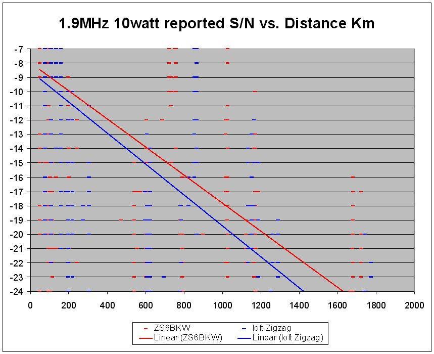
7 Some more plots this time 80m I've improved upon the accuracy of distances between stations this time, as the previous 160m plots used the same distance references for all the sites. This time I've plotted the correct distances between stations.
8 As before the spots were captured over a period of 1/2 hour in the early evening. By using continuous TX for a short period I was able to obtain over 500 spots. I sorted these into groups by TX antenna in use, and reporting station. I then averaged typically four spots from each station for each antenna. This is graphed in Excel to show the RX S/N against distance between my TX and the spotter. The measurements were made using 10 watts of transmitter power measured in a 2.4KHz IF bandwidth. As a guide SSB contacts are just about possible with S/N ratios of around 0 to +3dB, PSK at about -12 to -10dB and CW somewhere around -15 to -12dB. So as an example, if I m using the 6.5m vertical on 80m using 50 watts of SSB. Then I d expect to be able to have contacts at distances of up to about 100 to 150 Km. If I used PSK I d be able to increase the range to about 800Km, CW would extend the range to 2,000 Km or more. Note that there will be a large variation in S/N measurements between stations because they will be using different equipment and antennas and have differing background noise levels. So wherever possible I have tried to ensure that I have spots for each of the four antenna combinations from each of the stations. This should help to average out differences between plots, because each individual station will still be using the same RX system to for each of the four antenna spots at a given distance. Although overall accuracy is not brilliant, the general trend is still a very good indicator of performance. From this information I can determine that the loft antenna is about 8dB worse than the doublet, looking at the EZNEC plots it should only be about 3dB down. So it looks like I'm losing about 5dB somewhere in the building structure. The vertical is about 8dB worse than the Tee. EZNEC says it should be about 4dB down. So it looks like I'm loosing 4dB in the 4:1 Unun, coax and remote tuner. Notice that in this case the crossover point between the Doublet and Tee is much less noticeable. The EZNEC plots show the doublet gain to be comparable to the Tee at low angles of elevation, mainly because on 80m the doublet height above ground level (12m) is starting to become a greater proportion of a wavelength, improving its overall efficiency. For stations closer to my TX site (NVIS) I'm a bit surprised that there is only about 5dB difference between the Doublet and Tee, as the EZNEC plots suggest it should be more like 15dB. However this may be due to night time propagation and an unbalance in the horizontal sections of the Tee resulting in more upward gain than predicted. The high level of loss I was experiencing with the loft antenna worried me, so I thought I'd try another type of Zig Zag antenna. This time I increased the number of Zig Zags, reduced the spacing between them in order to maximise the 'straight' part of the antenna and added extra spokes to the end loading 'hats'. Careful adjustment of wire length ensured that any 'difficult' feed point impedances remained well outside the amateur bands.
9 This improved the performance on 160m and 80m by about 2dB. It also seems to have improved performance on the HF bands slightly, perhaps by about 1dB, although this is much more difficult to quantify. The antenna model suggests that this design should have slightly less gain on 160m and 80m than the previous skeleton Bicone. So some form of loading definitely helps improve the matching efficiency on these bands. This is primarily because it raises the resistive component of the feed point impedance, which is only in the region of a few ohms. However this is counteracted by the current distribution of the zigzag wire section which reduces the overall gain slightly. After some further modelling I thought that it would be worthwhile trying some loading coils in place of the Zigzag section. EZNEC suggested that this would provide about 1dB further improvement. So I wound some coils using 2.5mm wire along an 18 section of 2 plastic pipe. These provided about 200uH at 1.8MHz and with the end loading resonated the loft antenna on 1.9MHz. On 160m I couldn t measure any difference between Zigzag and inductor loading, however on 80m the performance was about 10dB worse than the Zigzag. So this was quickly abandoned. Investigation of the loading coil later revealed that it was self-resonant at about 2.5MHz, so it was presenting a capacitive reactance on 80m rather than the required inductance. So as the loading coil didn t seem to offer any advantages on 160m, where it was actually working correctly. I decided to revisit the Zigzag loading. This time when I reinstalled the wire I added some extra spokes to the end loading sections. This lowered the resonant frequency still further, so I was able to remove one of the Zigzag sections on each leg and still achieve resonance on 80m.
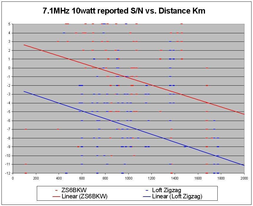
10 This time I used a different graphing method which gave much more accurate results. By comparing these results against values for each antenna obtained from an EZNEC model, I was able to determine that the revised loft mounted Zigzag now had approximately the same gain as the predicted value. 160m
11 80m
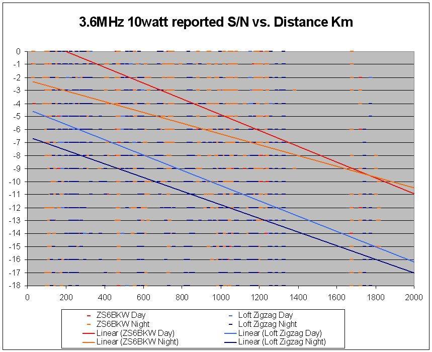
12 40m
13

14 This is substantially better than the 5dB loss I originally measured when using the Bicone antenna and is within a db of the modelled values. I conclude that this is the best result I am likely to obtain from a loft mounted wire antenna within the space available. However at some stage I would still like to perform tests with a screwdriver antenna for comparison purposes. M. Ehrenfried G8JNJ - V1.5 08/12/2009
The design of Ruthroff broadband voltage transformers M. Ehrenfried G8JNJ
 The design of Ruthroff broadband voltage transformers M. Ehrenfried G8JNJ Introduction I started investigating balun construction as a result of various observations I made whilst building HF antennas.
Chapter 6 Antenna Basics. Dipoles, Ground-planes, and Wires Directional Antennas Feed Lines
 Chapter 6 Antenna Basics Dipoles, Ground-planes, and Wires Directional Antennas Feed Lines Some General Rules Bigger is better. (Most of the time) Higher is better. (Most of the time) Lower SWR is better.
ANOTHER MULTIBAND WIRE ANTENNA
 ANOTHER MULTIBAND WIRE ANTENNA Above The multiband long wire with balun (cover is off) by Ron VK3AFW. I wanted to build a simple wire antenna dedicated to 30 m and 17m for operation during the 2015 ILLW
4/29/2012. General Class Element 3 Course Presentation. Ant Antennas as. Subelement G9. 4 Exam Questions, 4 Groups
 General Class Element 3 Course Presentation ti ELEMENT 3 SUB ELEMENTS General Licensing Class Subelement G9 Antennas and Feedlines 4 Exam Questions, 4 Groups G1 Commission s Rules G2 Operating Procedures
Feed Line Currents for Neophytes.
 Feed Line Currents for Neophytes. This paper discusses the sources of feed line currents and the methods used to control them. During the course of this paper two sources of feed line currents are discussed:
I recently came across a No-Counterpoise antenna described by designed by Peter Millis M3KXZ and based on an original design by K9ESE.
 M3KXZ 'no counterpoise' antenna I recently came across a No-Counterpoise antenna described by designed by Peter Millis M3KXZ and based on an original design by K9ESE. Details of the antenna can be found
Cray Valley Radio Society. Real Life Wire Antennas
 Cray Valley Radio Society Real Life Wire Antennas 1 The basic dipole The size of an antenna is determined by the wavelength of operation In free space: ~3x10 8 m/s Frequency x Wavelength = Speed of Light,
The Terminated Coaxial Cage Monopole (TC2M) A new design of Broadband HF vertical antenna Martin Ehrenfried G8JNJ
 A new design of Broadband HF vertical antenna Martin Ehrenfried G8JNJ") The Terminated Coaxial Cage Monopole (TC2M) A new design of Broadband HF vertical antenna Martin Ehrenfried G8JNJ Please note that this information is provided free to individuals who wish to construct
The Terminated Coaxial Cage Monopole (TC2M) A new design of Broadband HF vertical antenna Martin Ehrenfried G8JNJ Please note that this information is provided free to individuals who wish to construct
General License Class Chapter 6 - Antennas. Bob KA9BHD Eric K9VIC
 General License Class Chapter 6 - Antennas Bob KA9BHD Eric K9VIC Learning Objectives Teach you enough to get all the antenna questions right during the VE Session Learn a few things from you about antennas
L. B. Cebik, W4RNL. 1. You want to get on 160 meters for the first time (or perhaps, for the first time in a long time).
.") L. B. Cebik, W4RNL The following notes rest on a small set of assumptions. 1. You want to get on 160 meters for the first time (or perhaps, for the first time in a long time). 2. You want to set up the
L. B. Cebik, W4RNL The following notes rest on a small set of assumptions. 1. You want to get on 160 meters for the first time (or perhaps, for the first time in a long time). 2. You want to set up the
G7FEK LIMITED SPACE ANTENNA
 80, 40, 30, 17, 15, 12 m see tet for 20 & 10m operation For 20m operation add red wire 16.5ft ( 5.1m) 24 ft (7.4m) Copyright 2009 G7FEK During the 1980s Mike, G7FEK, described a limited space antenna suitable
4 Antennas as an essential part of any radio station
 4 Antennas as an essential part of any radio station 4.1 Choosing an antenna Communicators quickly learn two antenna truths: Any antenna is better than no antenna. Time, effort and money invested in the
DO NOT COPY. Basic HF Antennas. Bill Shanney, W6QR
 Basic HF Antennas Bill Shanney, W6QR When I was first licensed in 1961 I didn t know much about antennas. I put up the longest wire that fit on my parent s lot at the lofty height of 25 and fed it with
Antennas and Propagation Chapters T4, G7, G8 Antenna Fundamentals, More Antenna Types, Feed lines and Measurements, Propagation
 Antennas and Propagation Chapters T4, G7, G8 Antenna Fundamentals, More Antenna Types, Feed lines and Measurements, Propagation =============================================================== Antenna Fundamentals
Basic Wire Antennas. Part II: Loops and Verticals
 Basic Wire Antennas Part II: Loops and Verticals A loop antenna is composed of a single loop of wire, greater than a half wavelength long. The loop does not have to be any particular shape. RF power can
ARNSW Balun Day. Balun construction
 ARNSW Balun Day Balun construction Typical Baluns All built from locally available components. Balun uses Most baluns are used to match the 50Ω output of a transceiver to an antenna. A centre fed dipole
Beams and Directional Antennas
 Beams and Directional Antennas The Horizontal Dipole Our discussion in this chapter is about the more conventional horizontal dipole and the simplified theory behind dipole based designs. For clarity,
A Triangle for the Short Vertical
 1 von 11 03.03.2015 12:37 A Triangle for the Short Vertical Operator L. B. Cebik, W4RNL Last month, I described a triangle array of three full-size vertical dipoles for 40 meters (with 30 meters as a bonus).
Chapter 5.0 Antennas Section 5.1 Theory & Principles
 Chapter 5.0 Antennas Section 5.1 Theory & Principles G3C11 (B) p.135 Which of the following antenna types will be most effective for skip communications on 40-meters during the day? A. A vertical antenna
The Fabulous Dipole. Ham Radio s Most Versatile Antenna
 The Fabulous Dipole Ham Radio s Most Versatile Antenna 1 What is a Dipole? Gets its name from its two halves One leg on each side of center Each leg is the same length It s a balanced antenna The voltages
CHAPTER 8 ANTENNAS 1
 CHAPTER 8 ANTENNAS 1 2 Antennas A good antenna works A bad antenna is a waste of time & money Antenna systems can be very inexpensive and simple They can also be very expensive 3 Antenna Considerations
End Fed Half Wave Antenna Coupler
 End Fed Half Wave Antenna Coupler The finished End Fed Half Wave antenna coupler. Centre fed half wave dipoles make great, simple and effective antennas for the HF bands. Sometimes however, the centre
ANTENNAS. I will mostly be talking about transmission. Keep in mind though, whatever is said about transmission is true of reception.
 Reading 37 Ron Bertrand VK2DQ http://www.radioelectronicschool.com ANTENNAS The purpose of an antenna is to receive and/or transmit electromagnetic radiation. When the antenna is not connected directly
ANTENNA BASICS FOR BEGINNERS
 ANTENNA BASICS FOR BEGINNERS PART 2 -DIPOLES DIPOLES -General MULTIBAND DIPOLES RF CHOKES 1 DIPOLES Several different variations of the dipole are also used, such as the folded dipole, short dipole, cage
Technician License. Course
 Technician License Course Technician License Course Chapter 4 Lesson Plan Module - 9 Antenna Fundamentals Feed Lines & SWR The Antenna System The Antenna System Antenna: Transforms current into radio waves
1) Transmission Line Transformer a. First appeared on the scene in 1944 in a paper by George Guanella as a transmission line transformer, the 1:1
 Transmission Line Transformer a. First appeared on the scene in 1944 in a paper by George Guanella as a transmission line transformer, the 1:1") 1) Transmission Line Transformer a. First appeared on the scene in 1944 in a paper by George Guanella as a transmission line transformer, the 1:1 Guanella Balun is the basic building Balun building block.
1) Transmission Line Transformer a. First appeared on the scene in 1944 in a paper by George Guanella as a transmission line transformer, the 1:1 Guanella Balun is the basic building Balun building block.
What is a BALUN or UNUN:
 What is a BALUN or UNUN: A device to connect different types of antennas to various feed lines. Can transform impedances, choke common mode or change balanced to unbalanced BALUN Balanced to Unbalanced
A short, off-center fed dipole for 40 m and 20 m by Daniel Marks, KW4TI
 A short, off-center fed dipole for 40 m and 20 m by Daniel Marks, KW4TI Version 2017-Nov-7 Abstract: This antenna is a 20 to 25 foot long (6.0 m to 7.6 m) off-center fed dipole antenna for the 20 m and
Milton Keynes Amateur Radio Society (MKARS)
") Milton Keynes Amateur Radio Society (MKARS) Intermediate Licence Course Feeders Antennas Matching (Worksheets 31, 32 & 33) MKARS Intermediate Licence Course - Worksheet 31 32 33 Antennas Feeders Matching
Milton Keynes Amateur Radio Society (MKARS) Intermediate Licence Course Feeders Antennas Matching (Worksheets 31, 32 & 33) MKARS Intermediate Licence Course - Worksheet 31 32 33 Antennas Feeders Matching
SWR myths and mysteries.
 SWR myths and mysteries. By Andrew Barron ZL3DW September 2012 This article will explain some of the often misunderstood facts about antenna SWR at HF and uncover some popular misconceptions. The questions
General Class License Theory III. Dick Grote K6PBF
 General Class License Theory III Dick Grote K6PBF K6pbfdick@gmail.com 1 Introduction In this session we will learn about: Feed Lines Antennas Safety As in the other theory classes, we will try to present
Coming next: Wireless antennas for beginners
 Coming next: Wireless antennas for beginners In other rooms: Logbook of the World (Sussex Suite) SO2R contest operation (Stable Suite) Wires for your wireless: Simple wire antennas for beginners dominic
Ground-Mounted Verticals. Dispelling the Myths and Misconceptions
 Dispelling the Myths and Misconceptions Let s start with a quiz on vertical antennas and radials. Answers will be there to discover, as we proceed through the presentation. To be most effective, a ground-mounted
USERS MANUAL for the. FB5 Antenna. a personal non-commercial project of the Florida Boys
 USERS MANUAL for the FB5 Antenna a personal non-commercial project of the Florida Boys AB4ET Dec.2003 1 The FB5 Antenna USERS MANUAL INDEX 1.0. Introduction 2.0. Design 3.0. Construction 4.0. Electrical
Improved Ionospheric Propagation With Polarization Diversity, Using A Dual Feedpoint Cubical Quad Loop
 Improved Ionospheric Propagation With Polarization Diversity, Using A Dual Feedpoint Cubical Quad Loop by George Pritchard - AB2KC ab2kc@optonline.net Introduction This Quad antenna project covers a practical
A Relatively Simple160/80 No Tune/No Switch Dual CW Band Trap Antenna Using the Spiderbeam Mast
 A Relatively Simple160/80 No Tune/No Switch Dual CW Band Trap Antenna Using the Spiderbeam Mast This project originated with my request to the Contesting Top Band forum for thoughts on a transportable
Least understood topics by most HAMs RF Safety Ground Antennas Matching & Feed Lines
 Least understood topics by most HAMs RF Safety Ground Antennas Matching & Feed Lines Remember this question from the General License Exam? G0A03 (D) How can you determine that your station complies with
Product Review: MFJ Band Rotatable Mini -Dipole Phil Salas AD5X
 Product Review: MFJ-1775 6-Band Rotatable Mini -Dipole Phil Salas AD5X Introduction When I received the 2006 MFJ catalog, their new MFJ-1775 compact dipole caught my attention. This antenna was appealing
Antennas Demystified Antennas in Emergency Communications. Scott Honaker N7SS
 Antennas Demystified Antennas in Emergency Communications Scott Honaker N7SS Importance of Antennas Antennas are more important than the radio A $5000 TV with rabbit ears will have a lousy picture Antennas
Technician License Course Chapter 4. Lesson Plan Module 9 Antenna Fundamentals, Feed Lines & SWR
 Technician License Course Chapter 4 Lesson Plan Module 9 Antenna Fundamentals, Feed Lines & SWR The Antenna System Antenna: Transforms current into radio waves (transmit) and vice versa (receive). Feed
AD5X. The 43-Foot Vertical. Phil Salas - AD5X Phil Salas AD5X. Richardson, Texas
 The 43-Foot Vertical Phil Salas - AD5X ad5x@arrl.net Outline Why a vertical? Ground Losses and Antenna Efficiency Why a 43-foot vertical? SWR-related coax and unun losses Matching Networks for 160- and
ANTENNAS Wires, Verticals and Arrays
 ANTENNAS Wires, Verticals and Arrays Presented by Pete Rimmel N8PR 2 1 Tonight we are going to talk about antennas. Anything that will conduct electricity can be made to radiate RF can be called an antenna.
Working Bouvet with the Innovative and Cheap N6MW, Bill Wortman
 Working Bouvet with the Innovative and Cheap N6MW, Bill Wortman Trying to work the upcoming early 2018 Bouvet Dxpedition for an all time new one (ATNO as we say) is a serious challenge for those with only
Users Manual. 200W HF/50MHz Band Auto Antenna Tuner. Model HC-200AT
 Users Manual 200W HF/50MHz Band Auto Antenna Tuner Model HC-200AT Caution 1. Never remove or open the tuner cover while transmitting. When there is RF in the circuits of the tuner, there will be high voltage
# -antenna (hash) 4 direction switchable array
 4 direction switchable array") # -antenna (hash) 4 direction switchable array Feasibility study Paper on CCF & OHDXF cruise 4.1.2012 Pekka Ketonen 4.2.2012 OH1TV 1 4 direction, instant switching 4.2.2012 OH1TV 2 Features Instant direction
# -antenna (hash) 4 direction switchable array Feasibility study Paper on CCF & OHDXF cruise 4.1.2012 Pekka Ketonen 4.2.2012 OH1TV 1 4 direction, instant switching 4.2.2012 OH1TV 2 Features Instant direction
Page 1The VersaTee Vertical 60m, 80m Modular Antenna System Tutorial Manual
 Page 1The VersaTee Vertical 60m, 80m Modular Antenna System Tutorial Manual by: Lou Rummel, KE4UYP Page 1 In the world of low band antennas this antenna design is unique in many different ways. 1. It is
Antenna? What s That? Chet Thayer WA3I
 Antenna? What s That? Chet Thayer WA3I Space: The Final Frontier Empty Space (-Time) Four dimensional region that holds everything Is Permeable : It requires energy to set up a magnetic field within it.
THE VK WINDOM. Seemed Like a Good Idea
 THE VK WINDOM Seemed Like a Good Idea Over the years there have been many articles about the Windom antenna. It was first popularized by a US amateur called Windom whose 40 m signal on this antenna was
Transforms and electrical signal into a propagating electromagnetic wave OR vise versa. - Transducer goes both ways. TX and RX antennas have
 Gary Rondeau AF7NX Transforms and electrical signal into a propagating electromagnetic wave OR vise versa. - Transducer goes both ways. TX and RX antennas have different jobs. For TX want to generate as
Antenna Design for FM-02
 Antenna Design for FM-02 I recently received my FM-02 FM transmitter which I purchased from WLC. I researched the forum on what antennas where being used by the DIY community and found a nice write-up
A Guide to building your own Portable Station Incorporating a ¼ Wave Vertical Antenna and a Ground Tuning Unit or GTU
 A Guide to building your own Portable Station Incorporating a ¼ Wave Vertical Antenna and a Ground Tuning Unit or GTU Date: 06.02.2016 By: Alex Ball VK2HAS Credits: I was introduced to the GTU by Dave
Portable Vertical Antenna for 75m & 40m
 Portable Vertical Antenna for 75m & 40m BOXBORO August 2012 Jacques VE2AZX Web: ve2azx.net 1 Objectives 1- Portable Antenna for 75m et 40m 2- Low radiation angle for DX 3- Efficient 4- Easy to install.
Technician Licensing Class T9
 Technician Licensing Class T9 Amateur Radio Course Monroe EMS Building Monroe, Utah January 11/18, 2014 January 22, 2014 Testing Session Valid dates: July 1, 2010 June 30, 2014 Amateur Radio Technician
Magnetic Loop Antenna - Topbands
 Magnetic Loop Antenna - Topbands Instruction Manual Thank you for purchasing this new product small Magnetic Loop Antenna Topbands. Manual contains important information. Please read all instructions carefully
Low Band Receiving Antennas
 Low Band Receiving Antennas (on a city lot) Ned Stearns, AA7A How do you know you need a Receive Antenna? Scenario #1 Many DX stations hear you much better than you hear them Scenario #2 When your DXerneighbor
Multibanding the W3DZZ
 Multibanding the W3DZZ G3XSD s personal aims: To build a wire antenna for 80/40/30 to complement the existing rebuilt original CobWebb 20/18/15/13/10, that fits the estate ( 70 X70 ) Secondary aims: To
Emergency Antennas. Presented by Ham Hilliard W4GMM
 Emergency Antennas Presented by Ham Hilliard W4GMM Dipole antenna Vertical antenna Random wire antenna Dipole antenna The half wave dipole antenna consists of a conductive wire or rod that is half the
A Dual 160 m and 80 m Vertical with Simple Matching
 A Dual 160 m and 80 m Vertical with Simple Matching Background My old 80 m inverted L, described briefly in another note, proved to be a substantial success in the mission to kill off 80 m DXCC in one
Magnetic Loop Antenna - Top Bands
 Magnetic Loop Antenna - Top Bands Instruction Manual Thank you for purchasing this new product small Magnetic Loop Antenna Top Bands. Manual contains important information. Please read all instructions
WCARES NEEDS YOU! CONSIDER MAKING A TECHNICAL PRESENTATION AT AN UPCOMING CHEW & CHAT MEETING LEARN SOMETHING NEW AND PRESENT
 WCARES NEEDS YOU! CONSIDER MAKING A TECHNICAL PRESENTATION AT AN UPCOMING CHEW & CHAT MEETING SHARE WHAT YOU KNOW LEARN SOMETHING NEW AND PRESENT IT CONTACT TIM AD4CJ AD4CJ@arrl.net 1 Transmission Line
MFJ-219/219N 440 MHz UHF SWR Analyzer TABLE OF CONTENTS
 MFJ-219/219N 440 MHz UHF SWR Analyzer TABLE OF CONTENTS Introduction...2 Powering The MFJ-219/219N...3 Battery Installation...3 Operation Of The MFJ-219/219N...4 SWR and the MFJ-219/219N...4 Measuring
CHAPTER 5 PRINTED FLARED DIPOLE ANTENNA
 CHAPTER 5 PRINTED FLARED DIPOLE ANTENNA 5.1 INTRODUCTION This chapter deals with the design of L-band printed dipole antenna (operating frequency of 1060 MHz). A study is carried out to obtain 40 % impedance
How to Blow Up Your Balun
 How to Blow Up Your Balun (and other things too ) By Dean Straw, N6BV Sea-Pac June 7, 2014 Photos courtesy Jim Brown, K9YC 1 This is What I Intend to do Today I will examine stresses placed on common-mode
ANTENNA THEORY WAVE PROPAGATION HF ANTENNAS
 ANTENNA THEORY WAVE PROPAGATION & HF ANTENNAS FREQUENCY SPECTRUM INFORMATION Frequency range American designator below 300 Hz..ELF (extremely Low Frequency) 300-3000 Hz..ILF (Intermediate Low Frequency)
Last year I described several Low Band RX antennas that would enable you to hear DX stations on 160, 80 and 40M. This will show you how to build
 Last year I described several Low Band RX antennas that would enable you to hear DX stations on 160, 80 and 40M. This will show you how to build transmit antennas that will help you break the pileups!
Jacques Audet VE2AZX. Nov VE2AZX 1
 Jacques Audet VE2AZX VE2AZX@amsat.org Nov. 2006 VE2AZX 1 - REASONS FOR USING A BALUN - TYPES OF BALUNS - CHECK YOUR BALUN WITH AN SWR ANALYZER - MEASURING THE IMPEDANCE OF A NUMBER OF FERRITES - IMPEDANCE
A 2 ELEMENT 30 METER PARASITIC VERTICAL ARRAY PROJECT
 A 2 ELEMENT 30 METER PARASITIC VERTICAL ARRAY PROJECT Having killed off the 5B-DXCC purely using LOTW, it was time for the addition of a new band. 30 meters was selected based on lack of sunspots and a
Antenna Modelling For Radio Amateurs Made Easier -Part 2
 Antenna Modelling For Radio Amateurs Made Easier -Part 2 G8ODE RSARS 1619 Even the simple formula for the quarter wave element hides some daunting complex science and mathematics that most of us are unaware.
NVIS, Another Look. Tom Sanders, W6QJI Ed Bruette, N7NVP
 NVIS, Another Look Tom Sanders, W6QJI Ed Bruette, N7NVP Regional Communications N.V.I.S. Near Vertical Incidence Skywave What is NVIS? Near Vertical Incident Skywave Cloud Warmer Propagation Theory NVIS
1.5 kw Automatic Remote Controlled Antenna Tuner for Verticals and other Unbalanced Antennas
 1.5 kw Automatic Remote Controlled Antenna Tuner for Verticals and other Unbalanced Antennas Mod. AT- 615U Short Form Manual 10/2010 Dipl.Ing. Klaus Bemmerer RF Communication Electronics Niendorf-Middeldor
4/25/2012. Supplement T9. 2 Exam Questions, 2 Groups. Amateur Radio Technician Class T9A: T9A: T9A: T9A:
 Amateur Radio Technician Class Element 2 Course Presentation ti ELEMENT 2 SUB-ELEMENTS Technician Licensing Class Supplement T9 Antennas, Feedlines 2 Exam Questions, 2 Groups T1 - FCC Rules, descriptions
TWO METER HOMEMADE SLIM JIM ANTENNA
 Gordon Gibby July 15, 2016 TWO METER HOMEMADE SLIM JIM ANTENNA WIRE: Start with a piece of solid #14 AWG household wire approximately 3 yards and 9 inches long (117 ) (It is easier to be a couple inches
Table of Contents. MFJ-1778 G5RV Multiband Antenna
 Table of Contents MFJ-1778 G5RV Multiband Antenna Introduction... 1 Theory Of Operation... 1 80 meter band:... 1 40 meter band:... 1 30 meter band:... 2 20 meter band:... 2 17 meter band:... 2 15 meter
Technician Licensing Class. Antennas
 Technician Licensing Class Antennas Antennas A simple dipole mounted so the conductor is parallel to the Earth's surface is a horizontally polarized antenna. T9A3 Polarization is referenced to the Earth
Connecting Your Rig To The Aether
 Connecting Your Rig To The Aether 1 Ward Harriman (AE6TY) Pacificon 18 1: of course, there is no Aether! Presentation Goals Review a common design to reinforce forgotten knowledge. Use that design to demonstrate
Lesson 11: Antennas. Copyright Winters Version 1.0. Preparation for Amateur Radio Technician Class Exam
 Lesson 11: Antennas Preparation for Amateur Radio Technician Class Exam Topics Antenna ½ wave Dipole antenna ¼ wave Vertical antenna Antenna polarization Antenna location Beam antennas Test Equipment Exam
RX Directional Antennas. Detuning of TX Antennas.
 1. Models Impact of Resonant TX antennas on the Radiation Pattern of RX Directional Antennas. Detuning of TX Antennas. Chavdar Levkov, lz1aq@abv.bg, www.lz1aq.signacor.com 2-element small loops and 2-element
Design of a Delta Loop September 26, 2016
 Design of a Delta Loop September 26, 2016 by K0ZR Introduction Why a Delta loop? A Delta loop can be made to radiate a horizontal or vertically polarized signal. In most cases one chooses the vertical
Tuned Loop Antenna 20 through 10 meters
 Tuned Loop Antenna 20 through 10 meters - Revised: 2015-11-06 At K0MPH, a tuned loop antenna is used on the 20, 15 and 10 meter bands. I was inspired by George Badger, February 2008 QST - The W6TC DX Loop,
TZ-RD-1740 Rotary Dipole Instruction Manual
 TZ-RD-1740 17/40m Rotary Dipole Instruction Manual The TZ-RD-1740 is a loaded dipole antenna for the 40m band and a full size rotary dipole for the 17m band. The antenna uses an aluminium radiating section
Antenna Fundamentals
 HTEL 104 Antenna Fundamentals The antenna is the essential link between free space and the transmitter or receiver. As such, it plays an essential part in determining the characteristics of the complete
An Overview of the G5RV Antenna:
 An Overview of the G5RV Antenna: Understanding its Design and Operation. Presented by: Mike Parkin GØJMI Concept of G5RV Antenna Slide 1 Introduction Mike Parkin: First licensed as G8NDJ in 1977. Became
Amateur Extra Manual Chapter 9.4 Transmission Lines
 9.4 TRANSMISSION LINES (page 9-31) WAVELENGTH IN A FEED LINE (page 9-31) VELOCITY OF PROPAGATION (page 9-32) Speed of Wave in a Transmission Line VF = Velocity Factor = Speed of Light in a Vacuum Question
FCC Technician License Course
 FCC Technician License Course 2014-2018 FCC Element 2 Technician Class Question Pool Presented by: Tamiami Amateur Radio Club (TARC) WELCOME To the third of 4, 3-hour classes presented by TARC to prepare
A TRANSMISSION LINE BALANCE TEST METER
 by Lloyd Butler VK5BR with modifications by Phil Storr VK5SRP. Here is a simple meter to check the balance of currents running in the two legs of a transmission line. It can be used to check the balance
ANTENNA DESIGN FOR FREE USING MMANA-GAL SOFTWARE
 ANTENNA DESIGN FOR FREE USING MMANA-GAL SOFTWARE 1. AVAILABLE ANTENNA DESIGN SOFTWARE EZNEC and 4nec2 are based upon the Numerical Electromagnetics Code, or NEC, which is a popular antenna modelling system
The New and Improved Carolina Windom Antenna and ½ Wave End Fed 20 Meter Vertical and Sloping Wire Antennas. EZNEC analysis by Pete Rimmel, N8PR
 The New and Improved Carolina Windom Antenna and ½ Wave End Fed 20 Meter Vertical and Sloping Wire Antennas EZNEC analysis by Pete Rimmel, N8PR Keeps RF off the Coax below this point / (part of)/ That
Multiband Vertical Antenna Project 2004 by Harold Melton, KV5R
 2004 by Harold Melton, KV5R Page 1 of 5 Printed 1/14/2004 05:02:00 PM Multiband Vertical Antenna Project 2004 by Harold Melton, KV5R Purpose If you could only have two antennas, what would they be? It
JC-5 4KW PEP, 1KW RMS AUTO ANTENNA COUPLER
 JC-5 4KW PEP, 1KW RMS AUTO ANTENNA COUPLER 1) DIRECTLY CONTROLLED BY ICOM, ALINCO & KENWOOD. 2) INDEPENDENT CAPACITOR INPUT AND OUTPUT BLOCKS! 3) 3 mm COIL WIRE & INTERNAL FAN FOR THE BIG COILS! 4) DIPPED
MFJ-969 Versa Tuner II Instruction Manual
 MFJ-969 Versa Tuner II Instruction Manual General Information The MFJ-969 is a 300 watt RF output power antenna tuner that will match any transmitter or transceiver to virtually any antenna. Peak or average
Newcomers And Elmers Net: Wire Antennas Robert AK3Q
 Newcomers And Elmers Net: Wire Antennas 02-07-16 Robert AK3Q Wire antennas represent one of the greatest values in the radio hobby world. For less than the cost of a good meal out on the town you can buy
Emergency Antennas VHF / UHF - FM. HF Voice, CW, or Digital
 1 Emergency Antennas VHF / UHF - FM HF Voice, CW, or Digital 2 Antennas for VHF Quarter Wave Vertical Half Wave Vertical Vertical Dipole J-Pole 3 Design Parameters Primarily line of sight Mounted on trunk
A Tri Band Antenna for 2 meters, 220 MHz, and 70cm Antenna Without Radials. By: Edison Fong (WB6IQN)
") A Tri Band Antenna for 2 meters, 220 MHz, and 70cm Antenna Without Radials By: Edison Fong (WB6IQN) Twenty years ago a single band handie talkie would have been adequate for emergency use since almost
A Tri Band Antenna for 2 meters, 220 MHz, and 70cm Antenna Without Radials By: Edison Fong (WB6IQN) Twenty years ago a single band handie talkie would have been adequate for emergency use since almost
Portable Magnetic Loop Antenna. KG5EAO Rick Bono
 Portable Magnetic Loop Antenna KG5EAO Rick Bono April 2, 2016 Overview Develop a Portable magnetic loop antenna for use on HF bands running QRP. Portable and easy to deploy Ideally run on the 40m through
An SWR-Feedline-Reactance Primer Part 1. Dipole Samples
 An SWR-Feedline-Reactance Primer Part 1. Dipole Samples L. B. Cebik, W4RNL Introduction: The Dipole, SWR, and Reactance Let's take a look at a very common antenna: a 67' AWG #12 copper wire dipole for
Antenna. NO5V Rick Bono
 Portable End Fed Half Wave Antenna NO5V Rick Bono October 15, 2016 Overview Develop a Portable End Fed Half Wave Antenna Portable and easy to deploy Multiband capability Resonant Antenna No Tuner Needed!
N0GW Log Periodic Installation
 N0GW Log Periodic Installation I am particularly happy with my HF log periodic beam antenna installation. This is my first tower mounted, rotatable, beam antenna. Before retiring and moving to the Ozarks,
TBARC Programs Antenna Modeling with 4NEC2. By Randy Rogers AD7ZU 2010
 TBARC Programs Antenna Modeling with 4NEC2 By Randy Rogers AD7ZU 2010 Getting Started 4NEC2 is a completely free windows based tool suite to aid in the design and optimization of antenna systems 4NEC2
The Three L-Antennas Wide Equal - Tall
 Wide Equal - Tall Dick Reid, KK4OBI A space saving antenna in the form of an upright L has been around the amateur radio world for a long time. References are found back to a QST article in the 60 s (Reference
Antennas! November 2018
 1 Antennas! November 2018 Agenda 6PM Show and Tell plus Demos in the Park 7PM Welcome: new members and visitors Announcements Antenna Overview Alpha Loop Antenna N6IET Vertical Colinear WB6MMQ Whip Dipole