Bob Brehm, AK6R Chief Engineer Palomar-Engineers.com
|
|
|
- Cuthbert Bishop
- 5 years ago
- Views:
Transcription

1 Bob Brehm, AK6R Chief Engineer Palomar-Engineers.com HAMCON September 2017 This presentation available on website Copyright Palomar Engineers, Inc.
2 End Fed Workshop Topics Popular End Fed Antenna Types How to choose an end fed antenna that fits your needs Secrets of Non-Resonant End Fed Antennas Typical Configurations that work all the time Feed Line Chokes, Counterpoises and Noise Filters Q & A as time permits Thinking cap time
3 Pros and Cons of different end fed antennas for newbies and old timers too!
.")

4 Anatomy of an End Fed Antenna The antenna impedance matching components (BOX "Z" above) to match the antenna impedance to the coax line impedance (usually 50 ohms). For non-resonant end antennas, the typical feed point impedance is 300 to 600 ohms and a 9:1 impedance transformer (e.g. 450 ohm average antenna impedance to 50 ohm coax, also know as a 9:1 unun). With end fed antennas, the coax is meant to radiate as part of the antenna system (serving as the "ground" or counterpoise) and you need to use a Feed line Choke (BOX "FC" above) to suppress the common mode current on the outside of the coax feed line so it does not enter the radio while transmitting and also to reduce common mode noise while receiving. The Feed line (FC) acts as a stop sign for RF current flowing back on the outside of the coax. The higher the choking resistance of the fed line choke, the less the coax braid RFI common mode current and the less noise enters the radio. The radio station is also a key component of the antenna system and has two functions: transmit and receive. Matching the transmitter to the coax feed line is often done with an antenna tuner and receiver systems should be installed to maximize signal to noise ratio. Reducing receiver noise is critical for weak signal reception and the use of coax noise filters AND receiver power supply lines (AC or DC) noise filters is usually needed for optimum reception.
5 End Fed Antenna Types End Fed Zepp End Fed Half Wave Non-Resonate End Fed
6 End Fed Zepp Pros Low loss Cons Uses ladder line Single band w/o antenna tuner High and long Needs feed line choke at antenna
7 End Fed Half Wave (EFHW) Pros Multi-band Efficient over ¼ wave Cons Long - requires a coil for multiband Complex matching unit (64:1) Needs feedline choke at antenna
8 Non-Resonant End Fed Antenna Pros Shorter than others Easy to deploy Good bandwidth Non critical length Lots of configurations Simple matching unit Cons Coax radiates Counterpoises
9 End Fed Antenna Choices Recap End Fed Zepp uses ladder line for matching to coax End Fed Half Wave is long and requires special high impedance/voltage matching Non-resonant end fed is shorter, uses simple matching and works many bands in less space and will work in many different configurations Question: How do I set up a non-resonant end fed?

10
11 Secrets to success with a Non- Resonant End Fed Antenna How to determine the wire length to use (antenna, coax and counterpoise lengths) How to match the antenna to coax cable (matching unit values and placement) Choosing a configuration that fits the location (vertical, sloper, inverted L, horizontal options) Choosing a feed line choke or noise filter How does these steps apply to your end fed?
12 How to determine the wire length Antenna Wire longer for better low band operation Coax Cable typically shorter than antenna 75% Counterpoises/radials use non-resonant length, raised, multiple and a nail in the ground Suggested wire lengths for 1-31 MHz operation (measured from Bullet wire terminal): Bands Covered (meters) Wire Length (feet) Minimum Coax Length (feet) , 49-63, , 54-64, , 55, 60, , 68-73, 85, 92, 102, , 141, 173,
13 End Fed SWR Factors Configuration shape (Inverted L, flat top, sloper, etc.) Length of coax feed line use recommended values Feed line choke placement at radio end Top feed or bottom feed feed sloper at top end Soil Conductivity put over salt water Length and number of counterpoise(s) use several with variable lengths, experiment with lengths for bands of interest Some SWR plots vs length

14 Bullet-31 SWR & Z (after 9:1) 15 vert, 16 horizontal, two 15 counterpoises

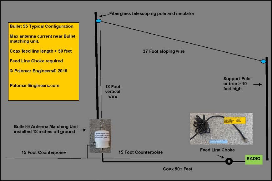
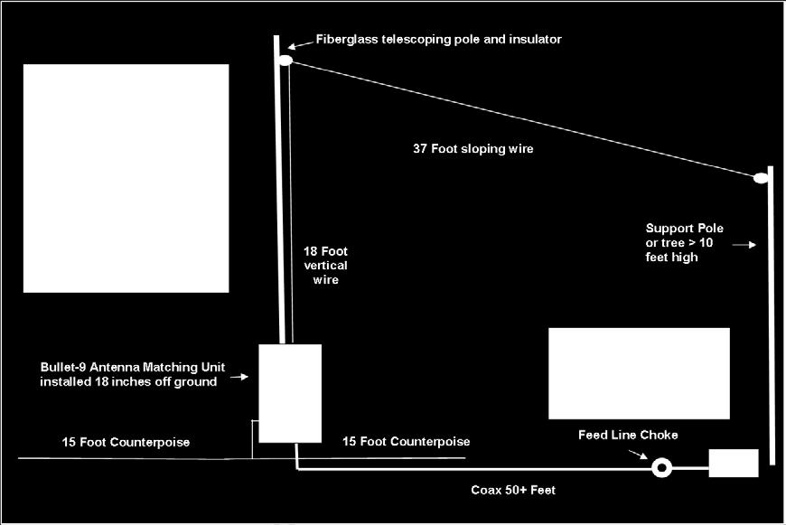
15 Bullet-55 SWR (after 9:1) 20 vertical, 35 horizontal, two 15 counterpoises, 1-61 MHz

16 Bullet-92 SWR & Z (after 9:1) 20 vertical, 72 horizontal, two 15 counterpoises, 24 to nail in ground, 1-31 MHz

17 Matching the antenna to coax cable UNUNs are your friend Antenna feed point impedance: Ω 9:1 transformer gives 33 to 100Ω to coax Connections for coax, antenna feed point and counterpoise Power Ratings PEP to match your station

18 High Power Ununs are available 1.5KW Model Similar I/O connections PEP rating up to 5KW


19 Antenna Configuration Options Vertical Sloper Up, Sloper Down Inverted L, U Horizontal

20 Typical End Fed Antenna Setup DIY

21 Lower noise floor = Higher SNR = More DX!


22 Choosing a Feed Line Choke Criteria to Consider Effective Frequency Range Adequate Choking Impedance > 500Ω Sufficient Power Rating Physical Size/weight Balun or unun output


23 Choose choking impedance > 500Ω at frequency of use Super Choker 1-10 MHz >2K 5KW PEP 1K-6K Z 3 pounds Verticals AM/RTTY Contesting Line isolator MHz >2K 1.5KW PEP 1K-6K Z 1 pound All coax lines Optional ground, static bleeder


 5KW")

24 Feedline Chokes for all antennas 1 MHz 60 MHz Medium choking Z ( Ω) 5KW PEP for RG213, only 5 beads needed over 30 MHz


25 A $10 DIY End Fed Feed Line Choke + C o a x = Ring Ferrite + ¼ Coax Cable = feed line choke 2-5K ohms Use at radio end of coax to stop transmitted signal from entering radio station. Remember the coax radiates in the non-resonant end fed antenna Use RG-8X/58 for low power, RG303/400 for high power > 1KW PEP What about lowering receiver noise?
26 Anatomy of an End Fed Antenna The antenna impedance matching components (BOX "Z" above) to match the antenna impedance to the coax line impedance (usually 50 ohms). For non-resonant end antennas, the typical feed point impedance is 300 to 600 ohms and a 9:1 impedance transformer (e.g. 450 ohm average antenna impedance to 50 ohm coax, also know as a 9:1 unun). With end fed antennas, the coax is meant to radiate as part of the antenna system (serving as the "ground" or counterpoise) and you need to use a Feed line Choke (BOX "FC" above) to suppress the common mode current on the outside of the coax feed line so it does not enter the radio while transmitting and also to reduce common mode noise while receiving. The Feed line (FC) acts as a stop sign for RF current flowing back on the outside of the coax. The higher the choking resistance of the fed line choke, the less the coax braid RFI common mode current and the less noise enters the radio. The radio station is also a key component of the antenna system and has two functions: transmit and receive. Matching the transmitter to the coax feed line is often done with an antenna tuner and receiver systems should be installed to maximize signal to noise ratio. Reducing receiver noise is critical for weak signal reception and the use of coax noise filters AND receiver power supply lines (AC or DC) noise filters is usually needed for optimum reception.


27 Coax Feed Line Noise Filters One of the best kept secrets in ham radio!!! Placed at RADIO END of coax feed line to suppress common mode current on coax braid between antenna feed point choke and radio higher choking impedance than most regular feed line chokes so greater attenuation of noise.

28 Unbalanced antennas need a ground to call home
29 Typical RFI Issues Keep antenna away from house wiring including AC power, Cable/Satellite feeds, telephone lines as these wires can act as antennas and overload attached electronics OR transmit spurious signals (and noise) to your antenna. Use Palomar RFI kits to solve RFI interference or noise issues in your own home or neighbor s. See website for more details.
30 Ham s Solution to Neighbor s RFI Source (transmitter or antenna ) Path Victim Clean up your transmitter/shack first Assess Neighbor s Problem Faulty device (device acting as receiver when not designed to be a radio receiver e.g. Telephone, HDTV) Determine frequency of transmitter that is causing the problem (may not be on all bands may not be you!) Find the path (or paths) to the Victim (Receiver) Choose the RFI choke kit for the frequency and path Choke the path, protect the device (externally)!


31 Transceiver/Amp RFI Kits Palomar RFI kits for all brands of transceivers and amplifiers Transceiver RFI Kit Linear Amplifier RFI Kit Clean up your transmitter RFI first


32 Neighborhood RFI Solutions Recommendation: Use RFI kits for specific problems, have neighbor purchase and install do not make mods to neighbors equipment! MOST problems are RFI picked up by AC power/phone lines so ferrite filters work well. Q & A Time
33 RFI Solutions Experts Palomar Engineers Website: Phone: Bob Brehm, AK6R Chief Engineer This presentation available on the website.
Bob Brehm, AK6R Chief Engineer Palomar-Engineers.com
 Bob Brehm, AK6R Chief Engineer Palomar-Engineers.com LAKESIDE - October 2017 This presentation available on website Copyright 2013-2017 Palomar Engineers, Inc. End Fed Workshop Topics Popular End Fed Antenna
Bob Brehm, AK6R Chief Engineer Palomar-Engineers.com
 Bob Brehm, AK6R Chief Engineer Palomar-Engineers.com EARS - October 2017 This presentation available on website Copyright 2013-2017 Palomar Engineers, Inc. Are you the SOURCE of RFI? IT S ALL YOUR FAULT
Bob Brehm, AK6R Chief Engineer Palomar-Engineers.com
 Bob Brehm, AK6R Chief Engineer Palomar-Engineers.com IDXC Visalia - April 2018 This presentation available on website Copyright 2013-2018 Palomar Engineers, Inc. Are you the SOURCE of RFI? IT S ALL YOUR
Bob Brehm, AK6R Chief Engineer Palomar-Engineers.com. PVARC April Copyright 2016 Palomar Engineers, Inc.
 Bob Brehm, AK6R Chief Engineer Palomar-Engineers.com PVARC April 2016 Copyright 2016 Palomar Engineers, Inc. Causing Neighborhood RFI? IT S ALL YOUR FAULT WITH THAT BIG ANTENNA! Receiving RFI from Neighborhood?
Bob Brehm, AK6R Chief Engineer Palomar-Engineers.com. Copyright 2015 Palomar Engineers, Inc.
 Bob Brehm, AK6R Chief Engineer Palomar-Engineers.com Copyright 2015 Palomar Engineers, Inc. RFI Workshop Objectives Review fundamentals of Common Mode Noise How ferrites work to suppress Common Mode noise
EVERY rotor control, remote antenna selector also has a common mode choke at each end of the cable!
 Radio Communication Choosing a Coax Feed Line Choke By Bob Brehm, AK6R RFI Tip Sheet #RC-1 How to choose feed line chokes, line isolators, baluns, or ununs for coax fed dipoles, verticals, hex beams, slopers,
Bob Brehm, AK6R Chief Engineer Palomar-Engineers.com. Copyright 2014 Palomar Engineers, Inc.
 Bob Brehm, AK6R Chief Engineer Palomar-Engineers.com Copyright 2014 Palomar Engineers, Inc. RFI Workshop Objectives Learn fundamentals of RFI How ferrites work to suppress RFI How to use ferrite kits to
Bob Brehm, AK6R Chief Engineer Palomar-Engineers.com. Copyright 2014 Palomar Engineers, Inc.
 Bob Brehm, AK6R Chief Engineer Palomar-Engineers.com Copyright 2014 Palomar Engineers, Inc. What is RFI? Radio Frequency Interference/Electromagnetic Interference (RFI/EMI) at radio frequencies A radio
1) Transmission Line Transformer a. First appeared on the scene in 1944 in a paper by George Guanella as a transmission line transformer, the 1:1
 Transmission Line Transformer a. First appeared on the scene in 1944 in a paper by George Guanella as a transmission line transformer, the 1:1") 1) Transmission Line Transformer a. First appeared on the scene in 1944 in a paper by George Guanella as a transmission line transformer, the 1:1 Guanella Balun is the basic building Balun building block.
1) Transmission Line Transformer a. First appeared on the scene in 1944 in a paper by George Guanella as a transmission line transformer, the 1:1 Guanella Balun is the basic building Balun building block.
Bob Brehm, AK6R Chief Engineer Palomar-Engineers.com. Copyright 2014 Palomar Engineers, Inc.
 Bob Brehm, AK6R Chief Engineer Palomar-Engineers.com Copyright 2014 Palomar Engineers, Inc. What is RFI? Radio Frequency Interference/Electromagnetic Interference (RFI/EMI) at radio frequencies A radio
What is a BALUN or UNUN:
 What is a BALUN or UNUN: A device to connect different types of antennas to various feed lines. Can transform impedances, choke common mode or change balanced to unbalanced BALUN Balanced to Unbalanced
The first thing to realize is that there are two types of baluns: Current Baluns and Voltage Baluns.
 Choosing the Correct Balun By Tom, W8JI General Info on Baluns Balun is an acronym for BALanced to UNbalanced, which describes certain circuit behavior in a transmission line, source or load. Most communications
Least understood topics by most HAMs RF Safety Ground Antennas Matching & Feed Lines
 Least understood topics by most HAMs RF Safety Ground Antennas Matching & Feed Lines Remember this question from the General License Exam? G0A03 (D) How can you determine that your station complies with
COAXIAL TRANSMISSION LINE COMMON-MODE CURRENT
 COAXIAL TRANSMISSION LINE COMMON-MODE CURRENT Introduction Coaxial transmission lines are popular for their wide frequency bandwidth and high resistance to electromagnetic interference (EMI). Coax cables
I recently came across a No-Counterpoise antenna described by designed by Peter Millis M3KXZ and based on an original design by K9ESE.
 M3KXZ 'no counterpoise' antenna I recently came across a No-Counterpoise antenna described by designed by Peter Millis M3KXZ and based on an original design by K9ESE. Details of the antenna can be found
Cray Valley Radio Society. Real Life Wire Antennas
 Cray Valley Radio Society Real Life Wire Antennas 1 The basic dipole The size of an antenna is determined by the wavelength of operation In free space: ~3x10 8 m/s Frequency x Wavelength = Speed of Light,
Table of Contents. MFJ-1778 G5RV Multiband Antenna
 Table of Contents MFJ-1778 G5RV Multiband Antenna Introduction... 1 Theory Of Operation... 1 80 meter band:... 1 40 meter band:... 1 30 meter band:... 2 20 meter band:... 2 17 meter band:... 2 15 meter
Jacques Audet VE2AZX. Nov VE2AZX 1
 Jacques Audet VE2AZX VE2AZX@amsat.org Nov. 2006 VE2AZX 1 - REASONS FOR USING A BALUN - TYPES OF BALUNS - CHECK YOUR BALUN WITH AN SWR ANALYZER - MEASURING THE IMPEDANCE OF A NUMBER OF FERRITES - IMPEDANCE
Technician Licensing Class T9
 Technician Licensing Class T9 Amateur Radio Course Monroe EMS Building Monroe, Utah January 11/18, 2014 January 22, 2014 Testing Session Valid dates: July 1, 2010 June 30, 2014 Amateur Radio Technician
The J-Pole Antenna. Gary Wescom
 The J-Pole Antenna Gary Wescom - 2018 Much has been written about the J-Pole antenna. A simple Google search will net days worth of reading material on the subject. That would tend to indicate this paper
Chapter 6 Antenna Basics. Dipoles, Ground-planes, and Wires Directional Antennas Feed Lines
 Chapter 6 Antenna Basics Dipoles, Ground-planes, and Wires Directional Antennas Feed Lines Some General Rules Bigger is better. (Most of the time) Higher is better. (Most of the time) Lower SWR is better.
How to Blow Up Your Balun
 How to Blow Up Your Balun (and other things too ) By Dean Straw, N6BV Sea-Pac June 7, 2014 Photos courtesy Jim Brown, K9YC 1 This is What I Intend to do Today I will examine stresses placed on common-mode
WCARES NEEDS YOU! CONSIDER MAKING A TECHNICAL PRESENTATION AT AN UPCOMING CHEW & CHAT MEETING LEARN SOMETHING NEW AND PRESENT
 WCARES NEEDS YOU! CONSIDER MAKING A TECHNICAL PRESENTATION AT AN UPCOMING CHEW & CHAT MEETING SHARE WHAT YOU KNOW LEARN SOMETHING NEW AND PRESENT IT CONTACT TIM AD4CJ AD4CJ@arrl.net 1 Transmission Line
An Introduction to Radio Frequency Interference
 An Introduction to Radio Frequency Interference Ron Hranac, N0IVN Member, ARRL EMC Committee ARRL Colorado Section Technical Specialist What is RFI? RFI is an abbreviation for radio frequency interference
User Guide. For. Alpha Antenna. Model: Multiband (Black Match)
") User Guide For Alpha Antenna Model: Multiband (Black Match) Manufactured by: Alpha Antenna 1.888.482.3249 Website: http://alphaantenna.com Available from the: AmateurRadioStore.com Website: https://amateurradiostore.com
User Guide For Alpha Antenna Model: Multiband (Black Match) Manufactured by: Alpha Antenna 1.888.482.3249 Website: http://alphaantenna.com Available from the: AmateurRadioStore.com Website: https://amateurradiostore.com
Nick Garner N3WG and George Zafiropoulos KJ6VU
 Nick Garner N3WG and George Zafiropoulos KJ6VU Introduction Over the last few years, there has been a significant increase in the number of radio amateurs interested in portable operating. This is due
ANTENNA BASICS FOR BEGINNERS
 ANTENNA BASICS FOR BEGINNERS PART 2 -DIPOLES DIPOLES -General MULTIBAND DIPOLES RF CHOKES 1 DIPOLES Several different variations of the dipole are also used, such as the folded dipole, short dipole, cage
Antennas and Stuff. John Kernkamp WB4YJT
 Antennas and Stuff John Kernkamp WB4YJT John Kraus W8JK June 28, 1910 - July 18, 2004 Invented the helical antenna, the corner reflector, and the W8JK End-Fire array. In 1950 designed and built the Big
Newcomers And Elmers Net: Wire Antennas Robert AK3Q
 Newcomers And Elmers Net: Wire Antennas 02-07-16 Robert AK3Q Wire antennas represent one of the greatest values in the radio hobby world. For less than the cost of a good meal out on the town you can buy
ANTENNAS Wires, Verticals and Arrays
 ANTENNAS Wires, Verticals and Arrays Presented by Pete Rimmel N8PR 2 1 Tonight we are going to talk about antennas. Anything that will conduct electricity can be made to radiate RF can be called an antenna.
Antenna Design for FM-02
 Antenna Design for FM-02 I recently received my FM-02 FM transmitter which I purchased from WLC. I researched the forum on what antennas where being used by the DIY community and found a nice write-up
4/29/2012. General Class Element 3 Course Presentation. Ant Antennas as. Subelement G9. 4 Exam Questions, 4 Groups
 General Class Element 3 Course Presentation ti ELEMENT 3 SUB ELEMENTS General Licensing Class Subelement G9 Antennas and Feedlines 4 Exam Questions, 4 Groups G1 Commission s Rules G2 Operating Procedures
4/25/2012. Supplement T9. 2 Exam Questions, 2 Groups. Amateur Radio Technician Class T9A: T9A: T9A: T9A:
 Amateur Radio Technician Class Element 2 Course Presentation ti ELEMENT 2 SUB-ELEMENTS Technician Licensing Class Supplement T9 Antennas, Feedlines 2 Exam Questions, 2 Groups T1 - FCC Rules, descriptions
The Fabulous Dipole. Ham Radio s Most Versatile Antenna
 The Fabulous Dipole Ham Radio s Most Versatile Antenna 1 What is a Dipole? Gets its name from its two halves One leg on each side of center Each leg is the same length It s a balanced antenna The voltages
Interference & Suppression Page 59
 INTERFERENCE Interference & Suppression Page 59 Front-End Overload, Cross-Modulation What is meant by receiver overload? Interference caused by strong signals from a nearby transmitter What is one way
Antenna. NO5V Rick Bono
 Portable End Fed Half Wave Antenna NO5V Rick Bono October 15, 2016 Overview Develop a Portable End Fed Half Wave Antenna Portable and easy to deploy Multiband capability Resonant Antenna No Tuner Needed!
Technician Licensing Class. Antennas
 Technician Licensing Class Antennas Antennas A simple dipole mounted so the conductor is parallel to the Earth's surface is a horizontally polarized antenna. T9A3 Polarization is referenced to the Earth
Wire Antennas For Limited Space
 Wire Antennas For Limited Space Jim Brown K9YC Santa Cruz, CA http://audiosystemsgroup.com Our Objectives Good Antennas Good efficiency Good predictable patterns Minimal noise pickup and RFI Inexpensive
General License Class Chapter 6 - Antennas. Bob KA9BHD Eric K9VIC
 General License Class Chapter 6 - Antennas Bob KA9BHD Eric K9VIC Learning Objectives Teach you enough to get all the antenna questions right during the VE Session Learn a few things from you about antennas
MFJ-219/219N 440 MHz UHF SWR Analyzer TABLE OF CONTENTS
 MFJ-219/219N 440 MHz UHF SWR Analyzer TABLE OF CONTENTS Introduction...2 Powering The MFJ-219/219N...3 Battery Installation...3 Operation Of The MFJ-219/219N...4 SWR and the MFJ-219/219N...4 Measuring
SOME USES FOR RF1,RF5 and VA1 ANALYSTS. SWR Measurement
 SOME USES FOR RF1,RF5 and VA1 ANALYSTS THE HANDIEST INSTRUMENTS IN DECADES! When you put up an antenna in the the old days, it could be a real struggle. The only way to tell if it was tuned to the right
Intermediate Course (5) Antennas and Feeders
 Antennas and Feeders") Intermediate Course (5) Antennas and Feeders 1 System Transmitter 50 Ohms Output Standing Wave Ratio Meter Antenna Matching Unit Feeder Antenna Receiver 2 Feeders Feeder types: Coaxial, Twin Conductors
Intermediate Course (5) Antennas and Feeders 1 System Transmitter 50 Ohms Output Standing Wave Ratio Meter Antenna Matching Unit Feeder Antenna Receiver 2 Feeders Feeder types: Coaxial, Twin Conductors
MFJ Balanced Line Tuner
 MFJ Balanced Line Tuner Introduction The MFJ-974H balanced line antenna tuner is a fully balanced true balanced line antenna tuner, providing superb current balance throughout a very wide matching range
Portable Vertical Antenna for 75m & 40m
 Portable Vertical Antenna for 75m & 40m BOXBORO August 2012 Jacques VE2AZX Web: ve2azx.net 1 Objectives 1- Portable Antenna for 75m et 40m 2- Low radiation angle for DX 3- Efficient 4- Easy to install.
Users Manual. 200W HF/50MHz Band Auto Antenna Tuner. Model HC-200AT
 Users Manual 200W HF/50MHz Band Auto Antenna Tuner Model HC-200AT Caution 1. Never remove or open the tuner cover while transmitting. When there is RF in the circuits of the tuner, there will be high voltage
HF Wire Antennas, EMI Contest Stations. WCARC November 2016 VE3KL
 HF Wire Antennas, EMI Contest Stations WCARC November 2016 VE3KL Introduction A Top Down View of a Radio Station(s) 1. Wire Antenna Design...Ideas needed.. 2. Dipoles and Unwanted Radiation (EMI) 3. A
Feed Line Currents for Neophytes.
 Feed Line Currents for Neophytes. This paper discusses the sources of feed line currents and the methods used to control them. During the course of this paper two sources of feed line currents are discussed:
Technician License Course Chapter 4. Lesson Plan Module 9 Antenna Fundamentals, Feed Lines & SWR
 Technician License Course Chapter 4 Lesson Plan Module 9 Antenna Fundamentals, Feed Lines & SWR The Antenna System Antenna: Transforms current into radio waves (transmit) and vice versa (receive). Feed
Basic Wire Antennas. Part II: Loops and Verticals
 Basic Wire Antennas Part II: Loops and Verticals A loop antenna is composed of a single loop of wire, greater than a half wavelength long. The loop does not have to be any particular shape. RF power can
Maximize power transfer Reduce feed line loss (if match is at the antenna) Make transmitters happy!
 Make transmitters happy!") Ward Silver - NØAX Impedance = ratio of voltage to current Mechanical analogies Mechanical impedance = ratio of torque to rate of rotation Vehicle transmission is an impedance converter Transfers power
Ward Silver - NØAX Impedance = ratio of voltage to current Mechanical analogies Mechanical impedance = ratio of torque to rate of rotation Vehicle transmission is an impedance converter Transfers power
Coming next: Wireless antennas for beginners
 Coming next: Wireless antennas for beginners In other rooms: Logbook of the World (Sussex Suite) SO2R contest operation (Stable Suite) Wires for your wireless: Simple wire antennas for beginners dominic
End Fed Half Wave Antenna Coupler
 End Fed Half Wave Antenna Coupler The finished End Fed Half Wave antenna coupler. Centre fed half wave dipoles make great, simple and effective antennas for the HF bands. Sometimes however, the centre
Improved Ionospheric Propagation With Polarization Diversity, Using A Dual Feedpoint Cubical Quad Loop
 Improved Ionospheric Propagation With Polarization Diversity, Using A Dual Feedpoint Cubical Quad Loop by George Pritchard - AB2KC ab2kc@optonline.net Introduction This Quad antenna project covers a practical
Technician Licensing Class. Lesson 4. presented by the Arlington Radio Public Service Club Arlington County, Virginia
 Technician Licensing Class Lesson 4 presented by the Arlington Radio Public Service Club Arlington County, Virginia 1 Quiz Sub elements T6 & T7 2 Good Engineering Practice Sub element T8 3 A Basic Station
Introduction. Understanding Power Ratings. Peak Reading SWR/Wattmeter
 Introduction The MFJ-962D is a "T" network roller inductor tuner with built-in antenna switching, RF power and SWR metering and a 1:1 balun. The largest amplifiers that can safely be used include the Heathkit
Chapter 5.0 Antennas Section 5.1 Theory & Principles
 Chapter 5.0 Antennas Section 5.1 Theory & Principles G3C11 (B) p.135 Which of the following antenna types will be most effective for skip communications on 40-meters during the day? A. A vertical antenna
Technician License. Course
 Technician License Course Technician License Course Chapter 4 Lesson Plan Module - 9 Antenna Fundamentals Feed Lines & SWR The Antenna System The Antenna System Antenna: Transforms current into radio waves
A Transmatch for Balanced or Unbalanced Lines
 A Transmatch for Balanced or Unbalanced Lines Most modern transmitters are designed to operate into loads of approximately 50 Ω. Solid-state transmitters produce progressively lower output power as the
and Related Topics W7KVI, HARC Original: 3/26/16
 Baluns, Ununs, and Related Topics W7KVI, HARC Original: 3/26/16 This Presentation Informal & brisk - 52 slides (too many unless you re an enthusiast!) Discussion encouraged if not extensive, interrupt
Beams and Directional Antennas
 Beams and Directional Antennas The Horizontal Dipole Our discussion in this chapter is about the more conventional horizontal dipole and the simplified theory behind dipole based designs. For clarity,
Antennas Demystified Antennas in Emergency Communications. Scott Honaker N7SS
 Antennas Demystified Antennas in Emergency Communications Scott Honaker N7SS Importance of Antennas Antennas are more important than the radio A $5000 TV with rabbit ears will have a lousy picture Antennas
Antenna Systems for the Recently Licensed Ham --3 Talks-- BVARC Meeting May 10 th, 2012
 Antenna Systems for the Recently Licensed Ham --3 Talks-- BVARC Meeting May 10 th, 2012 Understanding the Cardinal Rules of the Ham Radio Antenna System Rick Hiller -- W5RH Utilizing Your New Found Practical
ANTENNA THEORY WAVE PROPAGATION HF ANTENNAS
 ANTENNA THEORY WAVE PROPAGATION & HF ANTENNAS FREQUENCY SPECTRUM INFORMATION Frequency range American designator below 300 Hz..ELF (extremely Low Frequency) 300-3000 Hz..ILF (Intermediate Low Frequency)
Adjust Antenna Tuners Antenna Measurements Capacitor Measurement Measure Feed Point Impedance Measure Ground Loss Inductor Measurement
 The Micro908 antenna analyzer is an extremely useful instrument to have around the ham shack or homebrewer s workbench. This section describes the basic uses, as well as some advanced techniques for which
Optimizing Your Stations Performance
 Optimizing Your Stations Performance A few hints / techniques, recommendations for getting the most RF out to the Antenna from your HF, VHF / UHF station. Tonights Presenters: Doug Theriault NO1D John
ARNSW Balun Day. Balun construction
 ARNSW Balun Day Balun construction Typical Baluns All built from locally available components. Balun uses Most baluns are used to match the 50Ω output of a transceiver to an antenna. A centre fed dipole
1997 MFJ ENTERPRISES, INC.
 INSTRUCTION MANUAL CAUTION: Read All Instructions Before Operating Equipment MFJ ENTERPRISES, INC. 300 Industrial Park Road Starkville, MS 39759 USA Tel: 601-323-5869 Fax: 601-323-6551 VERSION 6C COPYRIGHT
FCC Technician License Course
 FCC Technician License Course 2014-2018 FCC Element 2 Technician Class Question Pool Presented by: Tamiami Amateur Radio Club (TARC) WELCOME To the third of 4, 3-hour classes presented by TARC to prepare
ALWAYS ATTACH THE SAFETY ROPE TO A STABLE SUPPORT BEFORE ATTEMPTING TO ATTACH THE UNIVERSAL MOUNT TO A WINDOW FRAME OR RAIL.
 MFJ-1623 Introduction The MFJ-1623 was designed to provide portable or permanent HF communications on 30 through 10 meters and VHF on 6 meters. The universal mount design allows the user to install the
G7FEK LIMITED SPACE ANTENNA
 80, 40, 30, 17, 15, 12 m see tet for 20 & 10m operation For 20m operation add red wire 16.5ft ( 5.1m) 24 ft (7.4m) Copyright 2009 G7FEK During the 1980s Mike, G7FEK, described a limited space antenna suitable
Transmission lines. Characteristics Applications Connectors
 Transmission lines Characteristics Applications Connectors Transmission Lines Connect They allow us to conduct RF Signals between our station components, they connect: Transceivers Antennas Tuners Amplifiers
MFJ-835 RF Ammeter. Introduction. Uses
 MFJ-835 RF Ammeter Introduction Congratulations on purchasing the MFJ-835 Balanced Line RF Ammeter. The MFJ-835 is designed for measuring balanced RF feedline current on 1.8-30 MHz while having low interaction
This paper is meant assist in the operation and understanding of the VIA Bravo Family of products.
 Abstract: This paper is meant assist in the operation and understanding of the VIA Bravo Family of products. Understanding the Display and its Readings: The VIA Bravo display provides graphical and numerical
Development of a noval Switched Beam Antenna for Communications
 Master Thesis Presentation Development of a noval Switched Beam Antenna for Communications By Ashraf Abuelhaija Supervised by Prof. Dr.-Ing. Klaus Solbach Institute of Microwave and RF Technology Department
WHY YOU NEED A CURRENT BALUN
 HF OPERATORS WHY YOU NEED A CURRENT BALUN by John White VA7JW NSARC HF Operators 1 What is a Balun? A BALUN is a device typically inserted at the feed point of a dipole-like antenna wire dipoles, Yagi
The Amazing MFJ 269 Author Jack Tiley AD7FO
 The Amazing MFJ 269 Author Jack Tiley AD7FO ARRL Certified Emcomm and license class Instructor, Volunteer Examiner, EWA Technical Coordinator and President of the Inland Empire VHF Club What Can be Measured?
Impedance, Reflections, and Transformations
 Impedance, Reflections, and Transformations Rocky Mountain Ham Radio University Chris Hamilton AE5IT 2017 December 16 Conventional wisdom: My antenna is useless above 1.5:1 SWR (Or is it 2:1? Or 3:1?)
1.5 kw Automatic Remote Controlled Antenna Tuner for Verticals and other Unbalanced Antennas
 1.5 kw Automatic Remote Controlled Antenna Tuner for Verticals and other Unbalanced Antennas Mod. AT- 615U Short Form Manual 10/2010 Dipl.Ing. Klaus Bemmerer RF Communication Electronics Niendorf-Middeldor
Last year I described several Low Band RX antennas that would enable you to hear DX stations on 160, 80 and 40M. This will show you how to build
 Last year I described several Low Band RX antennas that would enable you to hear DX stations on 160, 80 and 40M. This will show you how to build transmit antennas that will help you break the pileups!
Technician License Course Chapter 4
 Technician License Course Chapter 4 Propagation, Basic Antennas, Feed lines & SWR K0NK 26 Jan 18 The Antenna System Antenna: Facilitates the sending of your signal to some distant station. Feed line: Connects
Using Ferrite Beads Keep RF Out of TV Sets, Telephones, VCR's Burglar Alarms and other Electronic Equipment
 Using Ferrite Beads Keep RF Out of TV Sets, Telephones, VCR's Burglar Alarms and other Electronic Equipment RFI and TVI have been with us for a long time. Now we have microwave ovens, VCR's and many other
Choosing Your First HF Antenna
 The American Radio Relay League Choosing Your First HF Antenna Greater Fairfield Amateur Radio Assn May 1, 2017 Joel R. Hallas, W1ZR Contributing Editor, QST ARRL Copyright 2017, Joel Hallas, all rights
Introduction LOADING COIL COUNTERPOISE ATTACHMENT ANTENNA ATTACHMENT. Figure 1: MFJ-1625 Window/Balcony Mount Antenna
 Introduction MFJ-1625 The MFJ-1625 is a 200 Watt antenna tuner that was designed to provide portable or permanent HF communications on 80 through 10 meters and VHF on 6 meters. The universal mount design
Antennas and Propagation Chapters T4, G7, G8 Antenna Fundamentals, More Antenna Types, Feed lines and Measurements, Propagation
 Antennas and Propagation Chapters T4, G7, G8 Antenna Fundamentals, More Antenna Types, Feed lines and Measurements, Propagation =============================================================== Antenna Fundamentals
Amateur Extra Manual Chapter 9.4 Transmission Lines
 9.4 TRANSMISSION LINES (page 9-31) WAVELENGTH IN A FEED LINE (page 9-31) VELOCITY OF PROPAGATION (page 9-32) Speed of Wave in a Transmission Line VF = Velocity Factor = Speed of Light in a Vacuum Question
The Principle V(SWR) The Result. Mirror, Mirror, Darkly, Darkly
 The Result. Mirror, Mirror, Darkly, Darkly") The Principle V(SWR) The Result Mirror, Mirror, Darkly, Darkly 1 Question time!! What do you think VSWR (SWR) mean to you? What does one mean by a transmission line? Coaxial line Waveguide Water pipe Tunnel
The Principle V(SWR) The Result Mirror, Mirror, Darkly, Darkly 1 Question time!! What do you think VSWR (SWR) mean to you? What does one mean by a transmission line? Coaxial line Waveguide Water pipe Tunnel
M2 Antenna Systems, Inc. Model No: 2M HO LOOP
 M2 Antenna Systems, Inc. Model No: 2M HO LOOP SPECIFICATIONS: Model... 2M HO LOOP Frequency Range... 144 To 144.5 MHz Gain, Typical @ 10 ft.... 4 dbd @ 10 deg. Gain, 2 STK @ 82 & 132... 8 dbd @ 9 deg.
(TCPWCH) Common Mode Chokes
 Common Mode Chokes") Version: June 26, 2017 (TCPWCH) Common Mode Chokes Token Electronics Industry Co., Ltd. Web: www.token.com.tw Email: rfq@token.com.tw Taiwan: No.137, Sec. 1, Zhongxing Rd., Wugu District, New Taipei City,
Version: June 26, 2017 (TCPWCH) Common Mode Chokes Token Electronics Industry Co., Ltd. Web: www.token.com.tw Email: rfq@token.com.tw Taiwan: No.137, Sec. 1, Zhongxing Rd., Wugu District, New Taipei City,
Operating Station Equipment
 Amateur Radio License Class Operating Station Equipment Presented by Steve Gallafent October 3, 2007 Operating Station Equipment Modulation Modulation is the process of adding information to a radio signal
Milton Keynes Amateur Radio Society (MKARS)
") Milton Keynes Amateur Radio Society (MKARS) Intermediate Licence Course Feeders Antennas Matching (Worksheets 31, 32 & 33) MKARS Intermediate Licence Course - Worksheet 31 32 33 Antennas Feeders Matching
Milton Keynes Amateur Radio Society (MKARS) Intermediate Licence Course Feeders Antennas Matching (Worksheets 31, 32 & 33) MKARS Intermediate Licence Course - Worksheet 31 32 33 Antennas Feeders Matching
Technical Manual. AT5K-HP 3500 Watt Antenna Tuner. Designed and Manufactured in the USA Copyright 2014 Palstar, Inc.
 Palstar products are designed by Hams for Hams carrying on the Palstar tradition for high-quality products designed and manufactured in Ohio, USA. AT5K-HP 3500 Watt Antenna Tuner AT5K-HP 3500 Watt Antenna
MFJ-949E. tuner antenowy skrzynka antenowa. Instrukcja obsługi. importer:
 Instrukcja obsługi MFJ-949E tuner antenowy skrzynka antenowa importer: PRO-FIT Centrum Radiokomunikacji InRadio ul. Puszkina 80 92-516 Łódź tel: 42 649 28 28 e-mail: biuro@inradio.pl www.inradio.pl MFJ-949E
(TCPWCH) Common Mode Chokes
 Common Mode Chokes") Version: July 31, 2017 Electronics Tech. (TCPWCH) Common Mode Chokes Web: www.direct-token.com Email: rfq@direct-token.com Direct Electronics Industry Co., Ltd. China: 12F, Zhong Xing Industry Bld., Chuang
Version: July 31, 2017 Electronics Tech. (TCPWCH) Common Mode Chokes Web: www.direct-token.com Email: rfq@direct-token.com Direct Electronics Industry Co., Ltd. China: 12F, Zhong Xing Industry Bld., Chuang
QUICK REFERENCE GUIDE
 QUICK REFERENCE GUIDE Installation 1. Install a ground system for DC noise suppression and RFI suppression 2. Install your DC power supply 3. Install lightning protection. This will help protect more than
4 Antennas as an essential part of any radio station
 4 Antennas as an essential part of any radio station 4.1 Choosing an antenna Communicators quickly learn two antenna truths: Any antenna is better than no antenna. Time, effort and money invested in the
MFJ-834 RF Ammeter. Introduction. Uses
 MFJ-834 RF Ammeter Introduction Congratulations on purchasing the MFJ-834 RF Ammeter. The MFJ-834 is designed for measuring in-line RF feedline current on 1.8-30 MHz while having low interaction on the
Technician License. Course
 Technician License Course Technician License Course Chapter 4 Lesson Plan Module - 10 Practical Antennas The Dipole Most basic antenna The Dipole Most basic antenna The Dipole Total length is ½ wavelength
User Guide for the Alpha Antenna 6 40 or meter OCF Dipole
 User Guide for the Alpha Antenna 6 40 or 10 80 meter OCF Dipole Manufactured by: Alpha Antenna 1.888.482.3249 Website: http://alphaantenna.com User Guide Version 3.0 March 23, 2018 Page 1 Table of Contents
L. B. Cebik, W4RNL. 1. You want to get on 160 meters for the first time (or perhaps, for the first time in a long time).
.") L. B. Cebik, W4RNL The following notes rest on a small set of assumptions. 1. You want to get on 160 meters for the first time (or perhaps, for the first time in a long time). 2. You want to set up the
L. B. Cebik, W4RNL The following notes rest on a small set of assumptions. 1. You want to get on 160 meters for the first time (or perhaps, for the first time in a long time). 2. You want to set up the
SWR myths and mysteries.
 SWR myths and mysteries. By Andrew Barron ZL3DW September 2012 This article will explain some of the often misunderstood facts about antenna SWR at HF and uncover some popular misconceptions. The questions