Transmission lines. Characteristics Applications Connectors
|
|
|
- Eugene Higgins
- 5 years ago
- Views:
Transcription
1 Transmission lines Characteristics Applications Connectors
2 Transmission Lines Connect They allow us to conduct RF Signals between our station components, they connect: Transceivers Antennas Tuners Amplifiers VSWR Meters etc. To efficiently transfer power between these components the impedance of the transmission line must match the input or output impedances of the device(s) that connect. This is usually 50 Ω 2
3 What is a Transmission line? Equivalent of an infinitely long lossless transmission line using lumped circuit constants. A transmission line can be thought of as an infinite number of small series inductors on each leg of the transmission line with small capacitors coupling between the them. This model applies to all transmission lines whether open wire, ladder line, twin lead or coax. The characteristic impedance of the line is determined by the conductor diameters and the separation between them for open wire and twin lead transmission line and by the ratio of the center conductor diameter to the inside diameter of the shield surrounding the center conductor in coaxial cable. 3
4 Importance of VSWR It is important that your transmitter operates into a matching impedance to prevent damage A common misconception is that your VSWR must be 1:1. A 1:1 VSWR implies a perfect match between the transmitter and the antenna system. It is possible to have a low VSWR and an antenna system that is a poor radiator. A dummy load may have a 1:1 VSWR but it will not radiate your signal. An effective antenna may not exhibit a perfect 1:1 VSWR 4
5 Expressing Impedance Mismatch (VSWR/Return Loss /Reflection Coefficient/Return loss) The concept of VSWR is easy to grasp and its importance in an antenna system does not require an engineering degree to understand. VSWR (Voltage Standing Wave Ratio) Reflection Coefficient Mismatch Loss Return Loss 5
6 VSWR Example calculation For a transmission line with a max voltage of 10 volts and a minimum voltage of 5 volts: Emax 10 VSWR= = = 2.0 Emin 5 VSWR is normally shown as the ratio to one or in this case the VSWR would be stated as 2.0 : 1 6
7 Reflection coefficient Example calculation Reflection coefficient (ρ) Is the ratio between the two impedances ρ = (Z Zo) / (Z + Zo) For an antenna of 100 Ω and a transmitter with a 50 Ω output with no reactive (imaginary) component ρ = (100 50) / ( ) or ρ =50/150 or ρ =.333 7
8 VSWR Using Reflection coefficient Example For an antenna of 100 Š and a transmitter with a 50 Š output (with no reactive or imaginary component) VSWR= (1+ p)/ (1 p) VSWR= (1+.333) / (1.333) or VSWR= 1.333/.667 or VSWR= 2.00 VSWR is normally shown as the ratio to one or in this case the VSWR would be stated as 2.0 : 1 8
9 Return Loss Example Return Loss Return Loss (RL) is the ratio of the forward power to the reflected power in db. A perfect load would have infinite return loss meaning that no power would be returned to the source (transmitter). A short or open would have zero db return loss meaning that there is zero db loss in the reflected signal relative to the forward signal meaning it was totally reflected back to the source (transmitter). RL= 10 (log10 (ρ²)) For an antenna of 100 Ω and a transmitter with a 50 Ω output (with no reactive or imaginary component) RL= 10 (log10 (.333²)) RL = 10 (log10 (.1109)) RL = 9.55dB 9
10 Mismatch Error Loss Example For an antenna with a reflection coefficient of.333 (or a VSWR of 2.0 : 1) Mismatch Loss = 10 (log (1 ρ²)) Mismatch Loss = 10 (log (1 (.333)²)) Mismatch Loss = 10 (log (1.1109)) Mismatch Loss = 10 (log (.8891)) Mismatch Return Loss = 10 (.0510) Mismatch Return Loss =.510 db 10

11 Comparison of Methods To Express Mismatch 11
12 The Ideal Situation Except for handie talkies, most antennas are not connected directly to a transmitter. The antenna is usually located some distance from the transmitter and requires a feedline to transfer power from the transmitter to the antenna. Transmitter Coaxial line Antenna 50 Ω 50 Ω 50 Ω 12
13 The Real World In order to transfer maximum power into a load (Antenna and Transmission line) impedance must match the generator (transmitter) impedance. Any difference, or mismatching, of these impedances would result in less than maximum power transfer to the antenna. In the case where the VSWR is 1:1 and the voltage and current will be constant over the whole length of the feedline. Any deviation from this situation will cause a "standing wave" of voltage and current to exist on the transmission line. 13
14 What Causes Standing Waves As the Forward and Reverse waves travel in opposite directions, they set up an interference pattern called a "standing wave". At certain places on the feedline the voltages will add producing a voltage maximum, and at others their relative phase difference will cause a voltage minimum to exist on the feedline. These maximum and minimum points occur exactly ¼ wavelength apart. ¼ λ Transmitter Standing wave Mismatched antenna 14
15 What Causes Standing Waves Measuring these standing waves in coaxial cable presents a problem since the "inside" of the cable is not readily available for measurements. ¼ λ Standing wave Consequently, VSWR measurements on coax are usually made at the transmitter end of the feedline. Therefore you are presented with the VSWR of the entire system which includes all losses associated with the entire system. 15
16 The Open or Shorted Line We want the waves on the transmission line (both voltage and current) to travel one way and deliver their energy to the desired load, which in this case may be an antenna where it is to be radiated. If all the energy gets reflected (for example, by an open or short circuit) at the end of the line, then none gets absorbed, producing a perfect "standing wave" on the line. Transmitter Coaxial line Open or Short This is a bad, undesired situation. In fact, when the power meant to be radiated comes back into the transmitter at full strength, it will usually burn out the electronics there. Modern transceivers will reduce their output power if you try to operate into a high VSWR load. 16
17 Long Feedlines Mask The load VSWR If we have a long run of lossey transmission line the load/antenna VSWR can look better than it actually is. Using return loss we can see that the signal going to the load is attenuated by 4 db and the signal returning from the mismatched load is attenuated an additional 4 db for a total return loss of 8 db. Transmitter Coaxial line Open or Short 4dB of loss Eight db of return loss is equal to a 2.33:1 VSWR. This is with an open or short (no antenna connected). This is the reason when you are testing an antenna VSWR it is important to measure it with a short low loss cable or with your VSWR meter directly at the antenna. 17
18 Standing Waves It doesn't take an open or short circuit to cause a reflected wave. All it takes is a mismatch in impedance between the Transmission line and the load. Transmitter Mismatched antenna If the reflected wave is not as strong as the forward wave, then a standing wave pattern will be observed, but the nulls will not be as deep nor the peaks as high as when an open or short is at the end of the transmission line. 18
19 It Is Not That Simple The actual impedance of any device is a complex number that has a reactive component associated with it. Z0 = Resistance + j Reactance or Z0 = R+j Impedance θ Reactance Resistance The phase (θ) of the impedance will be advanced or delayed depending upon whether the antenna appears inductive or capacitive to the feedline. In the real world VSWR calculations require including the imaginary value in our calculations. 19
20 The Smith Chart Complex impedance can bs shown on a smith chart so that the effects of changes in phase (cable length) can be easily seen Reactance Constant VSWR Nominal Resistance (50Ω) 20
21 The Full Reflection Coefficient Equation This is the equation that takes into account the reactive component of each of the impedances. ρ = (Z1+ j1) (Z2+ j2) (Z1+ j1) + (Z2+ j2) Similar substations would be made to the previously shown calculations to take into account the reactive component. 21
 using one of the following")

22 Measuring VSWR VSWR can be measured by a number of methods. You can measure the VSWR statically (without transmitting) using one of the following methods: MFJ 259 or 269 Antenna analyzers Antenna Noise Bridge from Palomar, MFJ, or from plans in the ARRL Handbook Spectrum analyzer with a tracking generator and an external directional coupler or RF bridge 22


23 Measuring VSWR Directional Couplers RF Bridges 23


24 Measuring VSWR VSWR can be measured using a VSWR meter or directional watt meter. measure the SWR/Power meter Directional Wattmeter's Many antenna tuners have built in directional wattmeter/vswr meters 24


25 Measuring VSWR For UHF and Microwave frequencies a Slotted Line and VSWR Indicator can be used 25


26 Matching The Transmitter To The Antenna Manual and automated antenna tuners Balun s and matching transformers 26

27 Matching The Transmitter To The Antenna You can use a balun or transformer to match a 50 Ω transmitter to a higher impedance antenna or transmission line A balun or transformer can also be used to connect unbalanced transmitter outputs to balanced transmission line 27
28 Antenna Tuners An antenna tuner, transmatch, doesn't really TUNE your antenna OR ANY PART OF IT! What an antenna tuner or transmatch does do, is transform the impedance at the antenna feed output at the radio to a value that your transceiver can handle, (typically 50 Ohms). When thinking about antenna tuners and SWR, it's important to remember that the tuner has no effect whatsoever on the SWR between itself and the antenna. It is the SWR between the transmitter and the tuner that is changed with the tuner controls. 28
29 Antenna Tuners In layman's terms, all a tuner does is act as a kind of adjustable impedance transformer between the radio and the antenna. It takes whatever impedance the antenna system presents, up to the design limits of the tuner, and attempts to convert it back to 50 Ohms or something reasonably close to that value for the transceiver. The transceiver will see a 50 Ohm impedance, and deliver it's maximum designed RF output. 29


30 Remote Antenna Tuners If the output of the tuner does not see 50 Ω if there is a mismatch is at the antenna there will be VSWR currents along the transmission line in between the tuner and the antenna that will produce additional signal loss. The ideal point for an antenna tuner is at the antenna end of the feed line just before the antenna itself. 30

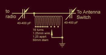
31 What Is Inside An Antenna Tuner? Variable inductors and capacitors L Configuration T Configuration pi Configuration Series Configuration 31
32 How does an Antenna Tuner work? Antenna Tuners are based upon lumped components as shown in the previous slide. The website listed below has a detailed explanation of how an antenna tuner actually matches one complex impedance to another, including the equations for solving the components needed to accomplish the match. 32


33 What Is Inside A Manual Antenna Tuner? 33
34 NOW LET'S LEARN TO Use the Antenna TUNER Most antenna tuners have an inductance rotary switch and two capacitors. (refer to photo) The capacitors are often labeled ANTENNA and TRANSMITTER. In some antenna tuners the inductance switch is replaced with a continuously variable inductance, known as a roller inductor. SHOCK HAZARD! NEVER TRANSMIT WITH THE TUNER COVER OFF! 34
35 NOW LET'S LEARN TO Use the Antenna TUNER Place both capacitor controls at their mid range positions. Don't trust the knob markers if this is your first experience with the tuner! If you are comfortable with the next procedure, remove the cover of the tuner and turn the knobs until the moving capacitor plates are only half meshed with the stationary plates. If the knobs are pointing to half scale with the reference markings on the knobs and front cover you are okay. If not, loosen their Allen screws and rotate the knobs so that they point to mid scale. Re tighten the knobs, replace the tuner cover and you're ready to go. 35
36 Best Practice caution Play it safe and un key before turning the inductor switch...unkey first...turn the switch...key up...repeat as needed until lowest SWR and maximum output. Be gentle to your radio; keep the key down periods as short as possible. Depending on the impedance at the antenna input (and the overall design of the tuner) you may not be able to obtain a flat 1:1 SWR on all frequencies and bands. Any thing below a 2:1 or lower will work well. Also important to remember is that your SWR will change, go up, as you tune further away from the frequency you used to "trick" your radio! So re check and re tune as needed as you move around the band. 36
. 5.")
37 Using the Antenna Tuner Tuning Procedure: 1. Position the TRANSMITTER control to mid scale. 2. Position the ANTENNA control to 0 on the corresponding scale. 3. Place the BYPASS/TUNE switch in the TUNE position. 4. Apply just enough power to obtain noticeable deflection on the reflected power meter or SWR meter (5 10 watts). 5. Adjust the INDUCTOR control for lowest deflection on the reflected power. WARNING: Never transmit while changing the INDUCTOR switch. 37
38 Using the Antenna Tuner 6. Carefully adjust the TRANSMITTER control for the lowest reflected power, then increase the ANTENNA control slightly and adjust the TRANSMITTER control for the lowest reflected power. Again, increase the ANTENNA control slightly and adjust the TRANSMITTER control for lowest reflected power. Repeat this process for lowest reflected power. Note: These controls interact. Go back and forth between these adjustments as many times as required until the lowest reflected power (best SWR) is obtained. 38
39 Using the Antenna Tuner 7. After the lowest reflected power (or SWR) is obtained in step 6, use the INDUCTOR switch to reduce the inductance one switch position (L is the lowest inductance setting and A is the highest inductance setting). Adjust the TRANSMITTER and ANTENNA controls for the lowest SWR. (A is the highest inductance setting). Tune for lowest SWR. Note: Always use as little inductance as possible. 8. After a low SWR is obtained, the transmitter power may be increased to the maximum allowable for your Antenna Tuner 9. Note the antenna tuner settings so you can return to them the next time you operate on that frequency. 39
40 The Cross Needle Power/VSWR Meter The cross needle power meter simultaneously shows forward and reflected power. Where the two needled cross there is an additional scale that shows the SWR 40

41 What is inside an Automatic Antenna Tuner? Firmware Directional Coupler Microprocessor Relays Capacitors Inductors 41
42 Automatic Tuners Now that you have seen what it takes to set up a manual antenna tuner you will appreciate the automatic antenna tuner. An automatic antenna tuner automatically goes through the same process you would do with a manual antenna tuner. A microprocessor monitors the antenna VSWR and uses relays to switch in inductance and capacitance until a satisfactory VSWR is obtained. Typically less than 5 seconds Many of today's automatic antenna tuners will store the frequency and settings so when you come back to that frequency the tuner can quickly go back to the previous settings making tune up very fast (1 2 seconds) 42

43 Properly Connecting An Antenna Tuner Optional 43
44 The VSWR Meter Whether part of you antenna tuner or a separate instrument a VSWR Meter consists of a directional coupler that samples forward and reflected voltage, a detector diode and apply the detected voltage to metering circuit. The metering circuit can have a switch to select forward and reflected power or dual meters. 44


45 Any Questions? Antenna tuner reference sites
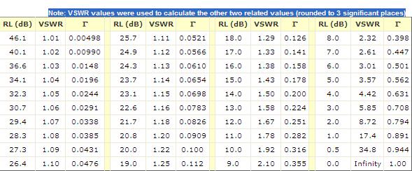
46 Conversion Chart 46
MFJ-941E Versa Tuner II GENERAL INFORMATION:
 GENERAL INFORMATION: MFJ VERSA TUNER II The MFJ-941E is designed to match virtually any transmitter to any antenna, including dipoles, inverted-vees, verticals, mobile whips, beams, random wires, and others
The Amazing MFJ 269 Author Jack Tiley AD7FO
 The Amazing MFJ 269 Author Jack Tiley AD7FO ARRL Certified Emcomm and license class Instructor, Volunteer Examiner, EWA Technical Coordinator and President of the Inland Empire VHF Club What Can be Measured?
MFJ-835 RF Ammeter. Introduction. Uses
 MFJ-835 RF Ammeter Introduction Congratulations on purchasing the MFJ-835 Balanced Line RF Ammeter. The MFJ-835 is designed for measuring balanced RF feedline current on 1.8-30 MHz while having low interaction
MFJ-219/219N 440 MHz UHF SWR Analyzer TABLE OF CONTENTS
 MFJ-219/219N 440 MHz UHF SWR Analyzer TABLE OF CONTENTS Introduction...2 Powering The MFJ-219/219N...3 Battery Installation...3 Operation Of The MFJ-219/219N...4 SWR and the MFJ-219/219N...4 Measuring
MFJ-904. tuner antenowy skrzynka antenowa. Instrukcja obsługi. importer:
 Instrukcja obsługi MFJ-904 tuner antenowy skrzynka antenowa importer: PRO-FIT Centrum Radiokomunikacji InRadio ul. Puszkina 80 92-516 Łódź tel: 42 649 28 28 e-mail: biuro@inradio.pl www.inradio.pl INTRODUCTION
MFJ-969 Versa Tuner II Instruction Manual
 MFJ-969 Versa Tuner II Instruction Manual General Information The MFJ-969 is a 300 watt RF output power antenna tuner that will match any transmitter or transceiver to virtually any antenna. Peak or average
MFJ-902. tuner antenowy skrzynka antenowa. Instrukcja obsługi. importer:
 Instrukcja obsługi MFJ-902 tuner antenowy skrzynka antenowa importer: PRO-FIT Centrum Radiokomunikacji InRadio ul. Puszkina 80 92-516 Łódź tel: 42 649 28 28 e-mail: biuro@inradio.pl www.inradio.pl INTRODUCTION
MFJ-834 RF Ammeter. Introduction. Uses
 MFJ-834 RF Ammeter Introduction Congratulations on purchasing the MFJ-834 RF Ammeter. The MFJ-834 is designed for measuring in-line RF feedline current on 1.8-30 MHz while having low interaction on the
VECTRONICS. VC-300DLP Antenna Tuner
 VECTRONICS VC-300DLP Antenna Tuner FEATURES The Vectronics VC-300DLP Antenna Tuner optimizes the performance of your antenna and transmitter, receiver, or transceiver by providing adjustable impedance
Vectronics VC-300D DIGITAL BARGRAPH ANTENNA TUNER
 Vectronics VC-300D DIGITAL BARGRAPH ANTENNA TUNER FEATURES The Vectronics VC-300D Antenna Tuner optimizes the performance of your antenna and transmitter, receiver, or transceiver by providing adjustable
MFJ-249B HF/VHF SWR ANALYZER
 TABLE OF CONTENTS MFJ-249B... 2 Introduction... 2 Powering The MFJ-249B... 3 Battery Installation... 3 Alkaline Batteries... 3 NiCd Batteries... 4 Power Saving Mode... 4 Operation Of The MFJ-249B...5 SWR
MFJ-949E. tuner antenowy skrzynka antenowa. Instrukcja obsługi. importer:
 Instrukcja obsługi MFJ-949E tuner antenowy skrzynka antenowa importer: PRO-FIT Centrum Radiokomunikacji InRadio ul. Puszkina 80 92-516 Łódź tel: 42 649 28 28 e-mail: biuro@inradio.pl www.inradio.pl MFJ-949E
VECTRONICS HFT-1500 Digital Bargraph Antenna Tuner
 Table of Contents FEATURES... 1 SPECIFICATIONS... 1 FRONT PANEL INDICATORS AND CONTROLS... 1 CONTROLS... 1 REAR PANEL CONNECTORS... 1 OTHER... 2 CONTOLS / CONNECTORS... 2 FRONT PANEL FUNCTIONS... 2 REAR
Introduction. Understanding Power Ratings. Peak Reading SWR/Wattmeter
 Introduction The MFJ-962D is a "T" network roller inductor tuner with built-in antenna switching, RF power and SWR metering and a 1:1 balun. The largest amplifiers that can safely be used include the Heathkit
Technician License. Course
 Technician License Course Technician License Course Chapter 4 Lesson Plan Module - 9 Antenna Fundamentals Feed Lines & SWR The Antenna System The Antenna System Antenna: Transforms current into radio waves
Technician License Course Chapter 4. Lesson Plan Module 9 Antenna Fundamentals, Feed Lines & SWR
 Technician License Course Chapter 4 Lesson Plan Module 9 Antenna Fundamentals, Feed Lines & SWR The Antenna System Antenna: Transforms current into radio waves (transmit) and vice versa (receive). Feed
SWR myths and mysteries.
 SWR myths and mysteries. By Andrew Barron ZL3DW September 2012 This article will explain some of the often misunderstood facts about antenna SWR at HF and uncover some popular misconceptions. The questions
ALWAYS ATTACH THE SAFETY ROPE TO A STABLE SUPPORT BEFORE ATTEMPTING TO ATTACH THE UNIVERSAL MOUNT TO A WINDOW FRAME OR RAIL.
 MFJ-1623 Introduction The MFJ-1623 was designed to provide portable or permanent HF communications on 30 through 10 meters and VHF on 6 meters. The universal mount design allows the user to install the
Milton Keynes Amateur Radio Society (MKARS)
") Milton Keynes Amateur Radio Society (MKARS) Intermediate Licence Course Feeders Antennas Matching (Worksheets 31, 32 & 33) MKARS Intermediate Licence Course - Worksheet 31 32 33 Antennas Feeders Matching
Milton Keynes Amateur Radio Society (MKARS) Intermediate Licence Course Feeders Antennas Matching (Worksheets 31, 32 & 33) MKARS Intermediate Licence Course - Worksheet 31 32 33 Antennas Feeders Matching
The Principle V(SWR) The Result. Mirror, Mirror, Darkly, Darkly
 The Result. Mirror, Mirror, Darkly, Darkly") The Principle V(SWR) The Result Mirror, Mirror, Darkly, Darkly 1 Question time!! What do you think VSWR (SWR) mean to you? What does one mean by a transmission line? Coaxial line Waveguide Water pipe Tunnel
The Principle V(SWR) The Result Mirror, Mirror, Darkly, Darkly 1 Question time!! What do you think VSWR (SWR) mean to you? What does one mean by a transmission line? Coaxial line Waveguide Water pipe Tunnel
Amateur Extra Manual Chapter 9.4 Transmission Lines
 9.4 TRANSMISSION LINES (page 9-31) WAVELENGTH IN A FEED LINE (page 9-31) VELOCITY OF PROPAGATION (page 9-32) Speed of Wave in a Transmission Line VF = Velocity Factor = Speed of Light in a Vacuum Question
MFJ-945E. tuner antenowy skrzynka antenowa. Instrukcja obsługi. importer:
 Instrukcja obsługi MFJ-945E tuner antenowy skrzynka antenowa importer: PRO-FIT Centrum Radiokomunikacji InRadio ul. Puszkina 80 92-516 Łódź tel: 42 649 28 28 e-mail: biuro@inradio.pl www.inradio.pl MFJ-945E
1997 MFJ ENTERPRISES, INC.
 INSTRUCTION MANUAL CAUTION: Read All Instructions Before Operating Equipment MFJ ENTERPRISES, INC. 300 Industrial Park Road Starkville, MS 39759 USA Tel: 601-323-5869 Fax: 601-323-6551 VERSION 6C COPYRIGHT
4/29/2012. General Class Element 3 Course Presentation. Ant Antennas as. Subelement G9. 4 Exam Questions, 4 Groups
 General Class Element 3 Course Presentation ti ELEMENT 3 SUB ELEMENTS General Licensing Class Subelement G9 Antennas and Feedlines 4 Exam Questions, 4 Groups G1 Commission s Rules G2 Operating Procedures
Technician Licensing Class. Lesson 4. presented by the Arlington Radio Public Service Club Arlington County, Virginia
 Technician Licensing Class Lesson 4 presented by the Arlington Radio Public Service Club Arlington County, Virginia 1 Quiz Sub elements T6 & T7 2 Good Engineering Practice Sub element T8 3 A Basic Station
Chapter 12: Transmission Lines. EET-223: RF Communication Circuits Walter Lara
 Chapter 12: Transmission Lines EET-223: RF Communication Circuits Walter Lara Introduction A transmission line can be defined as the conductive connections between system elements that carry signal power.
Central Electronics Model 600L Linear Amplifier
 INTRODUCTION This manual has been reproduced by James Lawrence, NA5RC, a 600L owner. Text no longer applicable such as insurance claim with the carrier has been deleted. Some capitalization and grammar
Introduction LOADING COIL COUNTERPOISE ATTACHMENT ANTENNA ATTACHMENT. Figure 1: MFJ-1625 Window/Balcony Mount Antenna
 Introduction MFJ-1625 The MFJ-1625 is a 200 Watt antenna tuner that was designed to provide portable or permanent HF communications on 80 through 10 meters and VHF on 6 meters. The universal mount design
MFJ Balanced Line Tuner
 MFJ Balanced Line Tuner Introduction The MFJ-974H balanced line antenna tuner is a fully balanced true balanced line antenna tuner, providing superb current balance throughout a very wide matching range
A Transmatch for Balanced or Unbalanced Lines
 A Transmatch for Balanced or Unbalanced Lines Most modern transmitters are designed to operate into loads of approximately 50 Ω. Solid-state transmitters produce progressively lower output power as the
MFJ ENTERPRISES 300 INDUSTRIAL PARK STARKVILLE, MS USA
 MFJ-819 MOBILE SWR/WATTMETER INSTRUCTION MANUAL PLEASE READ THIS MANUAL BEFORE OPERATING THIS EQUIPEMENT! MFJ ENTERPRISES 300 INDUSTRIAL PARK STARKVILLE, MS 39759 USA www.mfjenterprises.com 662-323-5869
VC-300D VECTRONICS R. Digital Bar Graph Antenna Tuner. Owner's Manual. CAUTION: Read All Instructions Before Operating Equipment!
 VC-300D Digital Bar Graph Antenna Tuner CAUTION: Read All Instructions Before Operating Equipment! VECTRONICS R... the finest amateur radio products made 300 Industrial Park Road Starkville, MS 39759 (662)
Cray Valley Radio Society. Real Life Wire Antennas
 Cray Valley Radio Society Real Life Wire Antennas 1 The basic dipole The size of an antenna is determined by the wavelength of operation In free space: ~3x10 8 m/s Frequency x Wavelength = Speed of Light,
7. Experiment K: Wave Propagation
 7. Experiment K: Wave Propagation This laboratory will be based upon observing standing waves in three different ways, through coaxial cables, in free space and in a waveguide. You will also observe some
Desktop/Remote Four-Position Antenna/Transceiver Switch
 Desktop/Remote Four-Position Antenna/Transceiver Switch INTRODUCTION The MFJ-4724 is a versatile multiple antenna/transceiver switch designed to switch up to four 50-ohm antenna systems or four transceivers
2006 MFJ ENTERPRISES, INC.
 Model MFJ-842 INSTRUCTION MANUAL CAUTION: Read All Instructions Before Operating Equipment MFJ ENTERPRISES, INC. 300 Industrial Park Road Starkville, MS 39759 USA Tel: 662-323-5869 Fax: 662-323-6551 VERSION
Transmission lines carry RF
 Transmission Line asics Technical techniques: primer for transmission lines Part I n understanding of transmission lines and tips on using them as transformers and filters can help techs properly configure
MFJ-208 VHF SWR Analyzer
 MFJ-208 VHF SWR Analyzer Thank you for purchasing the MFJ-208 VHF SWR Analyzer. The MFJ-208 gives you a direct readout of your antenna's SWR without the need for formulas or indirect readings. The MFJ-
VSWR Page 1 of 7. The Effects of VSWR on Transmitted Power. P =(Z1-Z o. +Z o )/(Z 1. are complex numbers so "p" is also a complex number.
/(Z 1. are complex numbers so p is also a complex number.") VSWR Page 1 of 7 The Effects of VSWR on Transmitted Power By James G. Lee, W6VAT No matter how long you have been a ham, sooner of later you will be involved in at least one discussion of something called
VSWR Page 1 of 7 The Effects of VSWR on Transmitted Power By James G. Lee, W6VAT No matter how long you have been a ham, sooner of later you will be involved in at least one discussion of something called
MICROWAVE AND RADAR LAB (EE-322-F) LAB MANUAL VI SEMESTER
 LAB MANUAL VI SEMESTER") 1 MICROWAVE AND RADAR LAB (EE-322-F) MICROWAVE AND RADAR LAB (EE-322-F) LAB MANUAL VI SEMESTER RAO PAHALD SINGH GROUP OF INSTITUTIONS BALANA(MOHINDERGARH)123029 Department Of Electronics and Communication
1 MICROWAVE AND RADAR LAB (EE-322-F) MICROWAVE AND RADAR LAB (EE-322-F) LAB MANUAL VI SEMESTER RAO PAHALD SINGH GROUP OF INSTITUTIONS BALANA(MOHINDERGARH)123029 Department Of Electronics and Communication
2001 MFJ ENTERPRISES, INC.
 ANTENNA ANALYZER Model MFJ-269Pro INSTRUCTION MANUAL CAUTION: Read All Instructions Before Operating Equipment MFJ ENTERPRISES, INC. 300 Industrial Park Road Starkville, MS 39759 USA Tel: 662-323-5869
1) Transmission Line Transformer a. First appeared on the scene in 1944 in a paper by George Guanella as a transmission line transformer, the 1:1
 Transmission Line Transformer a. First appeared on the scene in 1944 in a paper by George Guanella as a transmission line transformer, the 1:1") 1) Transmission Line Transformer a. First appeared on the scene in 1944 in a paper by George Guanella as a transmission line transformer, the 1:1 Guanella Balun is the basic building Balun building block.
1) Transmission Line Transformer a. First appeared on the scene in 1944 in a paper by George Guanella as a transmission line transformer, the 1:1 Guanella Balun is the basic building Balun building block.
2005 MFJ ENTERPRISES, INC.
 Model MFJ-209 INSTRUCTION MANUAL CAUTION: Read All Instructions Before Operating Equipment MFJ ENTERPRISES, INC. 300 Industrial Park Road Starkville, MS 39759 USA Tel: 662-323-5869 Fax: 662-323-6551 VERSION
A Stub Matched Lazy H for 17 M
 A Stub Matched Lazy H for 17 M Introduction The author has experimented with various configurations of the classic Lazy H antenna and a version optimised for operation on the 17 M band is shown in Figure
2006 MFJ ENTERPRISES, INC.
 Model MFJ-207 INSTRUCTION MANUAL CAUTION: Read All Instructions Before Operating Equipment MFJ ENTERPRISES, INC. 300 Industrial Park Road Starkville, MS 39759 USA Tel: 662-323-5869 Fax: 662-323-6551 VERSION
Preliminary Users Manual for the Self Contained Return Loss and Cable Fault Test Set with Amplified Wideband Noise Source Copyright 2001 Bryan K.
 Preliminary Users Manual for the Self Contained Return Loss and Cable Fault Test Set with Amplified Wideband Noise Source Copyright 2001 Bryan K. Blackburn Self Contained Test Set Test Port Regulated 12
Technician Licensing Class. Antennas
 Technician Licensing Class Antennas Antennas A simple dipole mounted so the conductor is parallel to the Earth's surface is a horizontally polarized antenna. T9A3 Polarization is referenced to the Earth
MULTIMEDIA UNIVERSITY FACULTY OF ENGINEERING LAB SHEET
 MULTIMEDIA UNIVERSITY FACULTY OF ENGINEERING LAB SHEET ELECTROMAGNETIC THEORY EMF2016 MW2 IMPEDANCE MEASUREMENT AND MATCHING EM Theory Faculty of Engineering, Multimedia University 2 EXPERIMENT MW2: IMPEDANCE
MFJ-203 Bandswitched Dip Meter
 MFJ-203 Bandswitched Dip Meter Thank you for purchasing the MFJ-203 Bandswitched Dip Meter. The MFJ-203 Bandswitched Dip Meter is a solid state bandswitched adaptation of the traditional grid dip meter.
TechFest Fall Bob Witte, KØNR Monument, CO
 TechFest Fall 2015 Bob Witte, KØNR bob@k0nr.com Monument, CO 1 Electrical Engineer 35 years in the Test and Measurement Industry HP, Agilent, Keysight Technologies Author of Electronic Test Instruments
Chapter 6 Antenna Basics. Dipoles, Ground-planes, and Wires Directional Antennas Feed Lines
 Chapter 6 Antenna Basics Dipoles, Ground-planes, and Wires Directional Antennas Feed Lines Some General Rules Bigger is better. (Most of the time) Higher is better. (Most of the time) Lower SWR is better.
L. B. Cebik, W4RNL. Basic Transmission Line Properties
 L. B. Cebik, W4RNL In the course of developing this collection of notes, I have had occasion to use and to refer to both series and parallel coaxial cable assemblies. Perhaps a few notes specifically devoted
How to use your antenna tuner.
 How to use your antenna tuner. There's more to it than what is in your manual or on most how to do it websites! http://www.arrl.org/tis/info/ant-tuner-op.html Here is a neat site with a "T" network simulator.
VECTRONICS. SWR-66 Dip Meter Adapter
 INTRODUCTION VECTRONICS SWR-66 Dip Meter Adapter Thank you for purchasing the SWR-66 Dip Meter Adapter. The SWR-66 Dip Meter Adapter works with your Vectronics SWR-584 HF/VHF SWR Analyzer. The SWR-66 Dip
COAXIAL TRANSMISSION LINE COMMON-MODE CURRENT
 COAXIAL TRANSMISSION LINE COMMON-MODE CURRENT Introduction Coaxial transmission lines are popular for their wide frequency bandwidth and high resistance to electromagnetic interference (EMI). Coax cables
Optimizing Your Stations Performance
 Optimizing Your Stations Performance A few hints / techniques, recommendations for getting the most RF out to the Antenna from your HF, VHF / UHF station. Tonights Presenters: Doug Theriault NO1D John
SOME USES FOR RF1,RF5 and VA1 ANALYSTS. SWR Measurement
 SOME USES FOR RF1,RF5 and VA1 ANALYSTS THE HANDIEST INSTRUMENTS IN DECADES! When you put up an antenna in the the old days, it could be a real struggle. The only way to tell if it was tuned to the right
Least understood topics by most HAMs RF Safety Ground Antennas Matching & Feed Lines
 Least understood topics by most HAMs RF Safety Ground Antennas Matching & Feed Lines Remember this question from the General License Exam? G0A03 (D) How can you determine that your station complies with
RF Transmission Lines & SWR
 RF Transmission Lines & SWR After installing the Antenna and finding a place for the Transceiver, you must connect the two together and the Antenna is usually located at some distance away from the Transceiver.
A TRANSMISSION LINE BALANCE TEST METER
 by Lloyd Butler VK5BR with modifications by Phil Storr VK5SRP. Here is a simple meter to check the balance of currents running in the two legs of a transmission line. It can be used to check the balance
CAVITY TUNING. July written by Gary Moore Telewave, Inc. 660 Giguere Court, San Jose, CA Phone:
 CAVITY TUNING July 2017 -written by Gary Moore Telewave, Inc 660 Giguere Court, San Jose, CA 95133 Phone: 408-929-4400 1 P a g e Introduction Resonant coaxial cavities are the building blocks of modern
Array Solutions Four Square Array Manual and User s Guide
 Array Solutions Four Square Array Manual and User s Guide Array Solutions Four Square Array Pattern Steering System Congratulations! You have selected one of the finest phased array steering systems made.
2012 MFJ ENTERPRISES, INC.
 Model MFJ-9213 INSTRUCTION MANUAL CAUTION: Read All Instructions Before Operating Equipment MFJ ENTERPRISES, INC. 300 Industrial Park Road Starkville, MS 39759 USA Tel: 662-323-5869 Fax: 662-323-6551 VERSION
2014 MFJ ENTERPRISES, INC.
 Model MFJ-209C INSTRUCTION MANUAL CAUTION: Read All Instructions Before Operating Equipment MFJ ENTERPRISES, INC. 300 Industrial Park Road Starkville, MS 39759 USA Tel: 662-323-5869 Fax: 662-323-6551 VERSION
MICROWAVE MICROWAVE TRAINING BENCH COMPONENT SPECIFICATIONS:
 Microwave section consists of Basic Microwave Training Bench, Advance Microwave Training Bench and Microwave Communication Training System. Microwave Training System is used to study all the concepts of
MFJ ARTIFICIAL GROUND
 MFJ ARTIFICIAL GROUND IMPORTANT: Please read entire manual before attempting to operate this equipment. This unit does not provide a DC electric ground. A separate wire will need to be run from the transmitter
Directional Couplers / SWR detectors for 145MHz - 435MHz. Easily and cheaply made. pa0nhc. Ver. E4;
 1 of 9 12/1/2008 9:46 PM
Model 3140B BiConiLog Antenna User Manual
 Model 3140B BiConiLog Antenna User Manual Model 3140B mounted onto a 7-TR tripod (not included) ETS-Lindgren L.P. reserves the right to make changes to any product described herein in order to improve
The Effects of VSWR on Transmitted Power
 The Effects of VSWR on Transmitted Power Zouhair Benmoussa and Don Barrick -- April 2006 What is VSWR and Why Should I Care? An ocean wavetrain traveling toward shore carries energy toward the beach. If
Adjust Antenna Tuners Antenna Measurements Capacitor Measurement Measure Feed Point Impedance Measure Ground Loss Inductor Measurement
 The Micro908 antenna analyzer is an extremely useful instrument to have around the ham shack or homebrewer s workbench. This section describes the basic uses, as well as some advanced techniques for which
db = 10 log10 (P1/P2) where P1 and P2 are two power levels
 where P1 and P2 are two power levels") A Quick Introduction to Decibels (db) Unit is the Bel: named after A.G. Bell who devised it for his work with deafness and audio sound levels. Now used for all frequencies of AC power. Decibel (db): -1
A Quick Introduction to Decibels (db) Unit is the Bel: named after A.G. Bell who devised it for his work with deafness and audio sound levels. Now used for all frequencies of AC power. Decibel (db): -1
MFJ-1048 PASSIVE PRESELECTOR. Introduction. Installation
 Introduction MFJ-1048 PASSIVE PRESELECTOR The MFJ-1048 is designed to reduce receive overload from strong out of band signals. It contains selective circuits that cover 1.6 to 33 MHz in six steps, providing
Improved Ionospheric Propagation With Polarization Diversity, Using A Dual Feedpoint Cubical Quad Loop
 Improved Ionospheric Propagation With Polarization Diversity, Using A Dual Feedpoint Cubical Quad Loop by George Pritchard - AB2KC ab2kc@optonline.net Introduction This Quad antenna project covers a practical
LRL Model 550B-SS Microwave Training Kit
 MICROWAVES FOR EVERYONE LRL Model 550B-SS Microwave Training Kit Microwave Training Kit 5 Experiments I-95 Industrial Park 651 Winks Lane Bensalem, PA 1900 800.53.399 15.638.1100 3rd edition INITIAL SET-UP
MFJ ENTERPRISES, INC.
 Model MFJ-962D Requires 9VDC Battery or 12VDC Source for Meter Operation INSTRUCTION MANUAL CAUTION: Read All Instructions Before Operating Equipment MFJ ENTERPRISES, INC. 300 Industrial Park Road Starkville,
TWO METER HOMEMADE SLIM JIM ANTENNA
 Gordon Gibby July 15, 2016 TWO METER HOMEMADE SLIM JIM ANTENNA WIRE: Start with a piece of solid #14 AWG household wire approximately 3 yards and 9 inches long (117 ) (It is easier to be a couple inches
RigExpert AA-170 Antenna Analyzer (0.1 to 170 MHz) User s manual
 User s manual") RigExpert AA-170 Antenna Analyzer (0.1 to 170 MHz) User s manual Table of contents 1. Description... 3 2. Specifications... 4 3. Precautions... 5 4. Operation... 6 4.1. Preparation for use... 6 4.2. Turning
RigExpert AA-170 Antenna Analyzer (0.1 to 170 MHz) User s manual Table of contents 1. Description... 3 2. Specifications... 4 3. Precautions... 5 4. Operation... 6 4.1. Preparation for use... 6 4.2. Turning
Technical Manual. AT5K-HP 3500 Watt Antenna Tuner. Designed and Manufactured in the USA Copyright 2014 Palstar, Inc.
 Palstar products are designed by Hams for Hams carrying on the Palstar tradition for high-quality products designed and manufactured in Ohio, USA. AT5K-HP 3500 Watt Antenna Tuner AT5K-HP 3500 Watt Antenna
Network Analysis Basics
 Adolfo Del Solar Application Engineer adolfo_del-solar@agilent.com MD1010 Network B2B Agenda Overview What Measurements do we make? Network Analyzer Hardware Error Models and Calibration Example Measurements
JEREMY HALEY, WG9T LONGMONT AMATEUR RADIO CLUB. Longmont Amateur Radio Club
 RF IMPEDANCE AND THE SMITH CHART JEREMY HALEY, WG9T LONGMONT AMATEUR RADIO CLUB 1 RESISTANCE, REACTANCE, AND IMPEDANCE RESISTANCE Energy conversion to heat. REACTANCE Capacitance: Energy storage in electric
Lesson 9: Base Stations
 Lesson 9: Base Stations Preparation for Amateur Radio Technician Class Exam Topics Home Stations Basic Station Layout RTTY and Data Communications Station Accessories Wavelengths Feed Lines Impedance-matching
Feed Line Currents for Neophytes.
 Feed Line Currents for Neophytes. This paper discusses the sources of feed line currents and the methods used to control them. During the course of this paper two sources of feed line currents are discussed:
Transmission Lines As Impedance Transformers
 Transmission Lines As Impedance Transformers Bill Leonard N0CU 285 TechConnect Radio Club 2017 TechFest Topics Review impedance basics Review Smith chart basics Demonstrate how antenna analyzers display
2006 MFJ ENTERPRISES, INC.
 2500 Watt SSB / CW Tuner Model MFJ-9982 INSTRUCTION MANUAL Requires 9V Battery or 12V DC Source for Meter Operation CAUTION: Read All Instructions Before Operating Equipment MFJ ENTERPRISES, INC. 300 Industrial
Build a Return Loss Bridge
 Build a Return Loss Bridge Used with your DVM, this simple bridge, diode detector and return loss techniques can help you measure cable loss and SWR at the antenna. The bridge does double duty as a hybrid
Transmission Lines. Chapter 24. Basic Theory of Transmission Lines
 Chapter 24 Transmission Lines Basic Theory of Transmission Lines The desirability of installing an antenna in a clear space, not too near buildings or power and telephone lines, cannot be stressed too
Transmission Line Signal Sampling By Don Steinbach, AE6PM
 Transmission Line Signal Sampling By Don Steinbach, AE6PM When I was finalizing the mechanical layout of my remotely-operated 3-position coaxial antenna switch (Fig. 1), I wanted to include a way to bring
StepperTune Remote Antenna Tuner Controller
 Remote Antenna Tuner Controller Firmware Version 50K22A December 2016 www.steppertune.com Gary Baker, K7EMF Phone 509-290-0414 Contents Page Location Of Controls and Terms...... 3 Introduction.... 4 Installation:
WHY YOU NEED A CURRENT BALUN
 HF OPERATORS WHY YOU NEED A CURRENT BALUN by John White VA7JW NSARC HF Operators 1 What is a Balun? A BALUN is a device typically inserted at the feed point of a dipole-like antenna wire dipoles, Yagi
ANTENNAS. I will mostly be talking about transmission. Keep in mind though, whatever is said about transmission is true of reception.
 Reading 37 Ron Bertrand VK2DQ http://www.radioelectronicschool.com ANTENNAS The purpose of an antenna is to receive and/or transmit electromagnetic radiation. When the antenna is not connected directly
Modifying The Heath HA-14 For 6 Meters Greg Chartrand - W7MY 4/22/07
 Introduction The Heathkit HA-14 was one of the few electron tube linear amplifiers intended for mobile use but few were purchased with the 12 volt mobile power supply. Most hams bought the HA-14 for base
Antenna Design for FM-02
 Antenna Design for FM-02 I recently received my FM-02 FM transmitter which I purchased from WLC. I researched the forum on what antennas where being used by the DIY community and found a nice write-up
Technician Licensing Class T9
 Technician Licensing Class T9 Amateur Radio Course Monroe EMS Building Monroe, Utah January 11/18, 2014 January 22, 2014 Testing Session Valid dates: July 1, 2010 June 30, 2014 Amateur Radio Technician
IntelliTuner Automatic Antenna Tuners
 TM IntelliTuner Automatic Antenna Tuners Models MFJ-991 and MFJ-994 INSTRUCTION MANUAL CAUTION: Read All Instructions Before Operating Equipment MFJ ENTERPRISES, INC. 300 Industrial Park Road Starkville,
AA-35 ZOOM. RigExpert. User s manual. Antenna and cable analyzer
 AA-35 ZOOM Antenna and cable analyzer RigExpert User s manual . Table of contents Introduction Operating the AA-35 ZOOM First time use Main menu Multifunctional keys Connecting to your antenna SWR chart
BY ALLEN W. KING,* W1CJL QST May 1955 *Project Engineer, Harvey-Wells Electronics, Inc., Southbridge, Mass.
 BY ALLEN W. KING,* W1CJL QST May 1955 *Project Engineer, Harvey-Wells Electronics, Inc., Southbridge, Mass. This comes close to being the ultimate in multiband antenna couplers, from the standpoint of
10 GHz Microwave Link
 10 GHz Microwave Link Project Project Objectives System System Functionality Testing Testing Procedures Cautions and Warnings Problems Encountered Recommendations Conclusion PROJECT OBJECTIVES Implement
Antennas Prof. Girish Kumar Department of Electrical Engineering Indian Institute of Technology, Bombay. Module 2 Lecture - 10 Dipole Antennas-III
 Antennas Prof. Girish Kumar Department of Electrical Engineering Indian Institute of Technology, Bombay Module 2 Lecture - 10 Dipole Antennas-III Hello, and welcome to todays lecture on Dipole Antenna.
RF Power Amplifier (RFPA) Designing a 'Output Tank Circuit'
 Designing a 'Output Tank Circuit'") RF Power Amplifier (RFPA) Designing a 'Output Tank Circuit' By Larry E. Gugle K4RFE, RF Design, Manufacture, Test & Service Engineer (Retired) Figure-1 Output 'Tank' Circuit Network in Low-Pass Filter
RF Power Amplifier (RFPA) Designing a 'Output Tank Circuit' By Larry E. Gugle K4RFE, RF Design, Manufacture, Test & Service Engineer (Retired) Figure-1 Output 'Tank' Circuit Network in Low-Pass Filter
Development of a noval Switched Beam Antenna for Communications
 Master Thesis Presentation Development of a noval Switched Beam Antenna for Communications By Ashraf Abuelhaija Supervised by Prof. Dr.-Ing. Klaus Solbach Institute of Microwave and RF Technology Department